EP2464141A2 - Ensemble formant moteur - Google Patents
Ensemble formant moteur Download PDFInfo
- Publication number
- EP2464141A2 EP2464141A2 EP11192384A EP11192384A EP2464141A2 EP 2464141 A2 EP2464141 A2 EP 2464141A2 EP 11192384 A EP11192384 A EP 11192384A EP 11192384 A EP11192384 A EP 11192384A EP 2464141 A2 EP2464141 A2 EP 2464141A2
- Authority
- EP
- European Patent Office
- Prior art keywords
- leg portion
- magnet
- motor assembly
- secured
- shaped element
- Prior art date
- Legal status (The legal status is an assumption and is not a legal conclusion. Google has not performed a legal analysis and makes no representation as to the accuracy of the status listed.)
- Granted
Links
Images




Classifications
-
- H—ELECTRICITY
- H04—ELECTRIC COMMUNICATION TECHNIQUE
- H04R—LOUDSPEAKERS, MICROPHONES, GRAMOPHONE PICK-UPS OR LIKE ACOUSTIC ELECTROMECHANICAL TRANSDUCERS; ELECTRIC HEARING AIDS; PUBLIC ADDRESS SYSTEMS
- H04R11/00—Transducers of moving-armature or moving-core type
- H04R11/02—Loudspeakers
-
- H—ELECTRICITY
- H04—ELECTRIC COMMUNICATION TECHNIQUE
- H04R—LOUDSPEAKERS, MICROPHONES, GRAMOPHONE PICK-UPS OR LIKE ACOUSTIC ELECTROMECHANICAL TRANSDUCERS; ELECTRIC HEARING AIDS; PUBLIC ADDRESS SYSTEMS
- H04R31/00—Apparatus or processes specially adapted for the manufacture of transducers or diaphragms therefor
- H04R31/006—Interconnection of transducer parts
-
- H—ELECTRICITY
- H04—ELECTRIC COMMUNICATION TECHNIQUE
- H04R—LOUDSPEAKERS, MICROPHONES, GRAMOPHONE PICK-UPS OR LIKE ACOUSTIC ELECTROMECHANICAL TRANSDUCERS; ELECTRIC HEARING AIDS; PUBLIC ADDRESS SYSTEMS
- H04R2209/00—Details of transducers of the moving-coil, moving-strip, or moving-wire type covered by H04R9/00 but not provided for in any of its subgroups
- H04R2209/024—Manufacturing aspects of the magnetic circuit of loudspeaker or microphone transducers
Definitions
- the present invention relates to a motor assembly for a hearing aid.
- the present invention relates to a motor assembly in which a part of a U-shaped element forms part of the at least a part of a magnet housing.
- the present invention relates to a transducer assembly comprising a motor assembly.
- the present invention relates to a method of forming welding magnets to a magnet housing.
- the present invention relates to a motor assembly for a transducer assembly for a hearing aid.
- the motor assembly comprises a magnet housing, a U-shaped element, a coil, and one or more magnets.
- the U-shaped element has a secured leg portion that is secured to the magnet housing, and a movable leg portion that is adapted to be secured to a diaphragm of the transducer assembly.
- the magnet housing encircles the one or more magnets and the movable leg portion in a plane having a normal that extends parallel to a general direction of the movable leg portion. At least a part of the magnet housing is defined by the secured leg portion.
- One advantage of providing a magnet housing at least a part of which is defined by the secured leg portion of the U-shaped element, is that a more compact construction/design may be achieved. It will be appreciated that the more compact the motor assembly is, the smaller the hearing aid may be and/or the more space is available for the remaining components of the hearing device.
- the combined height (in the Z-direction) of the U-shaped element and the magnet housing may be reduced.
- the overall dimension of the motor assembly in a direction (the Z-direction) extending through both legs of the U-shaped element may be reduced.
- one leg of the U-shaped element is positioned on top of the magnet housing, thus creating at least a two layer construction, in the area of overlap. It will be appreciated that this two layer construction is eliminated by using the design of the present invention.
- the transducer assembly may be adapted to transform electrical energy into sound.
- the transducer is adapted to transform electrical energy into mechanical energy (movement of the movable leg of the U-shaped element) which in turn creates the sound waves (by means of the diaphragm to which the movable leg portion is connected/coupled).
- the transducer/motor assembly may be adapted to be fitted into any hearing aid such as a Behind-the-Ear (BTE) device, an In the Ear (ITE) device, a Receiver in the Canal (RIC) device or any other hearing aid.
- BTE Behind-the-Ear
- ITE In the Ear
- RIC Receiver in the Canal
- hearing aid shall be understood as an electromagnetic device which is adapted to amplify and modulate sound and to output this sound inside the ear cannel of a user.
- the movable leg portion of the U-shaped element is secured to the diaphragm such that movement of the movable leg portion is transferred to the diaphragm. It will be appreciated that movement of the diaphragm causes sound waves to be generated.
- the movable leg portion is secured to the diaphragm by means of a diaphragm connecting member.
- the diaphragm connecting member may form a monolithic element with the U-shaped element.
- the diaphragm connecting member may by a separate element which is secured to the movable leg portion and to the diaphragm.
- the diaphragm may comprise a metal material such as aluminum, nickel, stainless steel or any other material that reinforces this area.
- the primary and the secondary parts which the inner space of the housing may be equally big (i.e. define substantially the same volume).
- one of the primary and the secondary parts may be bigger than the other, such as 200 percent bigger, such as 300 percent bigger, such as 400 percent bigger, such as 500 percent bigger, such as 600 percent bigger, such as 700 percent bigger, such as 800 percent bigger, such as 900 percent bigger, such as 1000 percent bigger, such as 1500 percent bigger.
- the U-shaped element defines the secured leg portion which is interconnected to the movable leg portion by means of a interconnecting portion. It will be appreciated that although one of the leg portions of the U-shaped element is designated "the secured leg portion", a part of this leg portion may move during use of the device as only the area securing the secured leg portion relative to the housing is prevented from moving relative to the housing, while the remaining part of the secured leg portion may move relative to the housing.
- the U-shaped element may be a monolithic element or made from several parts.
- the interconnecting portion is curved and/or U-shaped. In one embodiment, at least one of (and perhaps both) the leg portions are substantially straight. Each of the leg portions may define a tip end which is provided in the opposite end of the respective leg portion than the interconnecting portion.
- the present invention eliminates the two layer structure defined in the area of overlap of the magnet housing and the secured leg portion.
- the reason for this is that the secured leg portion forms a part of the magnet housing.
- the entire design may be thinner and more compact in the Z-direction.
- This provides the advantage that the vibrations in the device are reduced.
- the reduction of the vibrations can be explained in the following manner. During use, the tip of movable leg portion moves up and down (i.e., in a Z-direction). However, during use, the tip will also move forwards and backwards (i.e., in an X-direction) as the movable leg portion moves about the interconnecting portion.
- the amplitude of the movement in the X-direction is determined by the dimension of the interconnecting portion. If the interconnecting portion is tall the amplitude in the X-direction is large, whereas a small interconnecting portion causes the amplitude in the X-direction to be small. Thus, as the current invention allows for a shorter U-shaped element (in the Z-direction), the amplitude in the X-direction is smaller. This is highly desirable as a lower amplitude of any vibration in the device is desired by manufacturers of hearing aids.
- the dimensions of the U-shaped element are chosen such that the size of the force Fz of the vibrations in the Z-direction is substantially identical to the size of the force Fx of the vibrations in the X-direction.
- Fz is larger than Fx, such as 20 percent larger, such as 40 percent larger, such as 50 percent larger.
- Fz is smaller than Fx, such as 20 percent smaller, such as 40 percent smaller, such as 50 percent smaller.
- the height of the interconnecting element in the Z-direction may be less than four times the thickness of one of the leg portions in the Z-direction, such as less than three times the thickness, such as less than two times the thickness, such as less than one and a half times the thickness, such as less than one time the thickness.
- the movable leg portion is connected to the diaphragm in the area of the tip portion.
- the movable leg portion is connected to the diaphragm at a point in an area covering a fifth of the length of the movable leg portion and including the tip thereof, such as a fourth of the length of the movable leg portion (and including its tip), such as a third of the length of the movable leg portion (and including its tip).
- the secured leg portion is secured to the housing either directly or via one or more elements. In one embodiment, the secured leg portion is glued and/or welded and/or soldered to the housing.
- the coil is arranged to induce a magnetic field in the U-shaped element.
- the coil is arranged such that the movable leg portion extends through a passage defined by the coil.
- the coil may define a number of windings which encircle the passage. It will be appreciated that the coil may be substituted by any other means for inducing a magnetic field in the U-shaped element.
- the motor assembly may comprise one or more magnets.
- the magnets are preferably arranged inside the magnet housing.
- the magnets may be arranged close to or in direct contact with the magnet housing such that the magnet housing can conduct the magnetic flux of the magnets.
- the magnets are spaced apart such that a space is defined between the two magnets.
- the movable leg portion may be provided.
- One of the magnets is arranged such that its north pole is facing the movable leg portion, while the other of the magnets is arranged such that its south pole is facing the movable leg portion.
- the opposite pole of each of the two magnets is provided in direct contact with or close to the magnet housing such that the magnetic flux is conducted by the magnet housing from one magnet to the other. Accordingly, inductance of a magnetic field in the movable leg portion by means of the coil causes the movable leg portion to move towards one of the two magnets depending on the polarity of the magnetic field in the movable leg portion.
- the one magnet is provided close to or in direct contact with the magnet housing such that one of the poles of the magnet faces the magnet housing.
- the other of the poles faces a space defined between the magnet and the opposite side of the magnet housing.
- the movable leg portion is provided.
- induction of a magnetic field in the movable leg portion causes the movable leg portion to move closer to the magnet or closer to said opposite side of the magnet housing (i.e. away from the magnet).
- the magnet housing may encircle the one or more magnets and the movable leg portion in a predetermined plane.
- This predetermined plane may define a normal which extends parallel to a general direction of the movable leg portion (i.e. in the X-direction). In other words, the plane defines a right angle with the movable leg portion.
- the magnet housing defines four sides, three of which are defined by a substantially C-shaped element and a fourth of which is defined by the secured leg portion.
- the four sides may define a rectangular or quadrangular cross-section e.g. in a plane defining a normal to the general direction of the movable leg portion.
- the magnet housing defines four sides.
- the sides or the inner surface of the sides may define a rectangular or quadrangular cross-section in a plane which defines a normal to the general direction of the movable leg portion. At least a part of the four sides may be defined by the secured leg portion.
- the secured leg portion additionally defines a part of one or both of the neighboring sides of the magnet housing.
- the magnet housing defines an inner surface at least a part of which is defined by the secured leg portion.
- the magnet housing may define an outer surface at least a part of which is defined by the secured leg portion.
- the magnet housing defines one or more sides at least one of which defines a first part and a second part, the first part being defined by the secured leg portion and the second part being defined in the same plane as the first part.
- "in the same plane” shall be understood such that the plane shall extend through at least a part of the first part and through at least a part of the second part.
- the first and the second parts are arranged such that it is not possible to define a first plane extending parallel to the general direction (the X-direction) of the first secured leg portion which extends through only one of the first and the second part. In other words, any such first plane will extend through both the first and the second part. In the latter embodiment, it may not be possible to define a second plane which is parallel to the first plane and which extends through a part of the first and/or the second part, through which the first plane does not extend.
- the magnet housing may define one or more sides at least one of which defines a first part and a second part
- the first part may be defined by the first secured leg portion and the second part may form an extending of the first part in a plane defined by the secured leg portion.
- the second part may form an extension of the first part in the general direction of the secured leg portion, e.g. such that the second part defines an extension of the tip of the secured leg portion.
- the second part may define an extension in any direction in a plane extending through the general direction of the secured leg portion. Accordingly, the second part may form an extension in a direction transverse to the general direction of the secured leg portion.
- the second part may form an indentation for receiving the first part.
- a first and a second plane extend through the magnet housing, each of the planes define a normal which extends in a direction parallel to a general direction (the X-direction) of the movable leg portion.
- the first plane and the second planes are parallel to each other.
- the first plane may extend through both the first part and the second part of the magnet housing, while the second plane may extend through the second part only.
- the second plane may be closer to the tip of the secured leg portion than the first plane.
- said two planes also extend through the remaining parts/sides of the magnet housing.
- the first part may define at least one indentation adapted to receive a protrusion of the second part. Accordingly, the first part may define one indentation or two indentations or three indentations or four indentations etc.
- the second part may define at least one indentation adapted to receive a protrusion of the first part.
- the second part may define one indentation or two indentations or three indentations or four indentations etc.
- the two parts may define a plurality of protrusions and a plurality of indentations which are adapted to engage each other.
- the magnet housing may form a single layer structure when seen in a radial direction from the centre of gravity of that part of the movable leg portion which is encircled by the magnet housing.
- the single layer structure is formed when seen in a radial direction from a geometrical centre of the magnet housing.
- the magnet housing forms a single layer structure when seen in a radial direction from a geometrical centre of that part of the movable leg portion which is encircled by the magnet housing.
- the "geometrical centre" of one or more elements may be defined as the centre of the minimum circumcised circle and/or of the maximum inscribed circle.
- the minimum circumcised circle being defined as the smallest circle which encloses whole of the respective element(s).
- the maximum inscribed circle being defined as the largest circle that can be inscribed inside the respective element(s).
- the one or more magnets may comprise two magnets which are spaced apart so as to define a (three dimensional) space between the two magnets. This space may also be called a gab.
- the movable leg portion may be provided in this space.
- each of the one or more magnets may be attached to the magnet housing. At least one of the one or more magnets may be attached to the housing by means one or more of: welding, soldering and an adhesive.
- At least one of the one or more magnets is spaced apart from the magnet housing by means of a foil or an adhesive. In one embodiment, the magnet(s) is/are attached to the magnet housing by means of welding or by means of an adhesive.
- the present invention relates to a transducer assembly for a hearing aid comprising a housing, a first diaphragm, and a first motor.
- the first diaphragm divides a first inner space of the housing into a primary and a secondary part.
- the first motor assembly is arranged in accordance with any of the previous embodiments.
- the first motor assembly has a first movable leg portion which is secured to the first diaphragm.
- the transducer assembly further comprises a second diaphragm that divides a second inner space of the housing into the secondary and a tertiary part.
- a second motor assembly is provided accordance with any of the previous embodiments.
- the second motor assembly has a second movable leg portion that is secured to the second diaphragm.
- the present invention relates to a method of laser welding a magnet to a U-shaped element of a transducer assembly according to any of the preceding embodiments.
- the U-shaped element defines a secured leg portion and a movable leg portion.
- Each of the leg portions defines a first and a second opposite side.
- the method comprising the steps of providing the magnet on a first side of one of the leg portions of the U-shaped element, and directing a laser beam towards a welding zone of the second side of the same leg portion.
- the method further comprises maintaining the laser beam towards the welding zone until (i) said leg portion in the area of said welding zone has changed from a solid state to a melded state all the way through said leg portion from the second side to the first side, and (ii) at least a part of the magnet has changed from a solid state to a melted state.
- the method further comprises cooling the magnet and the U-shaped element such that the magnet and the U-shaped element are welded together in the area of the welding zone.
- the method further comprises forming an aperture in the area of the welding zone, wherein the aperture extends from the first side to the second side of the U-shaped element.
- the method further comprises subjecting, from the second side, an inner surface of the aperture and a visible zone of the magnet to a laser beam so as to cause the magnet to be welded to the U-shaped element.
- the visible zone is that part of the magnet which is visible when looking through the aperture formed in the U-shaped element.
- the method according to the second aspect of the invention may comprise any combination of features and elements of the invention according to the first aspect of the invention.
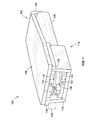
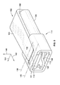
- Fig. 1 discloses an isometric view of a first embodiment.
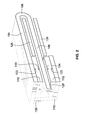
- Fig. 2 discloses a cross-sectional view of the first embodiment.
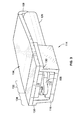
- Fig. 3 discloses an isometric view of a second embodiment.
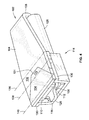
- Fig. 4 discloses an isometric view of a third embodiment.
- Fig. 5 discloses an isometric view of a fourth embodiment.
- Fig. 6 discloses a cross-sectional view of the first embodiment including the housing and the diaphragm.
- Fig. 7 discloses a cross-sectional view of a fifth embodiment.
- Fig. 8 discloses a cross-sectional view of the fifth embodiment.
- Figs. 9-11 disclose an isometric view of the first embodiment, wherein the magnets are laser welded to the magnet housing.
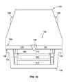
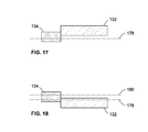
- Figs. 12-18 disclose different embodiments of "the same plane.”
- Figs. 1-2 disclose a first embodiment of a part of a transducer assembly 100 comprising a first U-shaped element 102 having a first secured leg portion 104 which is interconnected to a first movable leg portion 106 via a first interconnecting portion 108.
- the transducer assembly 100 comprises a first upper magnet 110 and a first lower magnet 112 which are provided inside a first magnet housing 114.
- the first magnet housing 114 is defined by a part of the first secured leg portion 104 and a first C-shaped element 116. Between the upper first magnet 110 and the lower first magnet 112 are separated by a space 118 in which the first movable leg portion 106 is provided.
- an first upper north pole 118 of the first upper magnet 110 is facing the first movable leg portion 106 while an first upper south pole 120 of the first upper magnet 110 is facing that part of the first secured leg portion 104 which forms part of the first magnet housing 114.
- a first lower north pole 122 of the lower first magnet 112 is facing the first C-shaped element 116 of the first magnet housing 114, while a first lower south pole 124 of the lower first magnet 112 is facing first movable leg portion 106.
- the first movable leg portion 106 is moved by inducing a magnetic field in the first U-shaped element 102 by means of a first coil 126. Depending on the polarity of the magnetic field in the area of the first movable tip 128 of the first movable leg portion 106, the first movable tip 128 is moved towards the first upper magnet 110 or towards the first lower magnet 112.
- the first C-shaped element 116 defines a first flanges 130 by means of which the first C-shaped element 116 is secured to the first secured leg portion 104. This may be done by means of an adhesive, welding or soldering or any other fastening method.
- Fig. 3 discloses a second embodiment which is an alternative to the first embodiment, and thus identical reference numbers refer to identical elements.
- the second embodiment only differs from the first embodiment in that one side of the first magnet housing 114 comprises an upper first part 132 and an upper second part 134.
- the upper first part 132 is formed by a part of the first secured leg portion 104, while the upper second part 134 is a separate element which forms an extension of the upper first part 132.
- Fig. 4 discloses a third embodiment which is an alternative to the first and the second embodiment, and thus identical reference numbers refer to identical elements.
- the upper first part 132 defines an indentation 131 for receiving a protrusion 133 of the upper second part 134. It will be appreciated a cross-section through a line 136 will only extend through the upper first part 132, while a cross-section though a line 138 will extend through both the upper first part 132 and the upper second part 134. Similarly, a cross-section through a line 140 only extends through the upper first part 132.
- Fig. 5 discloses a fourth embodiment which is yet another alternative to the previous embodiments. Again, identical reference numbers refer to identical elements.
- the upper second part 134 defines an indentation 131 for receiving the upper first part 132.
- a cross-section through the line 138 extends through both the upper first part 132 and the upper second part 134, whereas a cross-section through the line 140 extends through the upper second part 134 only.
- the upper second part 134 forms an extension of the upper first part 132 in the X-direction 142 and in the Y-direction 144.
- the X-direction 142 is the direction of the general direction of each of the legs 104, 106 of the first U-shaped element 102, whereas the Z-direction 146 is parallel to a line extending through and defining a normal to both legs 104,106.
- the Y-direction is a direction that is parallel to a normal to a plane defined by the X-direction 142 and the Z-direction 146.
- Figs. 3-5 are alternative embodiments of the design of Fig. 1 . These alternatives allows for the assembly order of the elements to be different.
- the transducer assembly 100 comprises a housing 148 comprising a first diaphragm 150.
- the housing 148 is divided into a primary part 152 and a secondary part 154 (only a part of which is disclosed in the drawing).
- the first movable leg portion 106 is secured to the first diaphragm 150 by means of a first diaphragm connecting element 156 whereby movement of the first movable leg portion 106 causes the first diaphragm 150 to move whereby sound is produced.
- Figs. 7-8 disclose a dual transducer assembly 158 comprising a first U-shaped element 102 having a first secured leg portion 104 which is interconnected to a first movable leg portion 106 via a first interconnecting portion 108.
- the transducer assembly 100 comprises a first upper magnet 110 and a first lower magnet 112 which are provided inside a first magnet housing 114.
- the first magnet housing 114 is defined by a part of the first secured leg portion 104 and a first C-shaped element 116.
- the dual transducer assembly 158 comprises a second U-shaped element 102' having a second secured leg portion 104' which is interconnected to a second movable leg portion 106' via a second interconnecting portion 108'.
- the transducer assembly 100 comprises a second upper magnet 110' and a second lower magnet 112' which are provided inside a second magnet housing 114'.
- the second magnet housing 114' is defined by a part of the second secured leg portion 104' and a second C-shaped element 116'.
- a primary part 152 and a secondary part 154 are defined by the space of the first transducer element.
- the second transducer element defines a tertiary part 154' and a quaternary part 152'. It will be appreciated that in the embodiment of the figure, the tertiary part 154' and the secondary part 154 are form the same compartment.
- Figs. 9-11 disclose a method of laser welding first upper magnet 110 to a first U-shaped element 102 of a transducer assembly 100 according to the first aspect of the invention. When carrying out the method, the following steps are carried out.
- a laser beam is directed towards a welding zone of the second side of the U-shaped element 102 such that the material of the U-shaped element 102 melts in the area of the welding zone.
- the laser beam is directed towards the welding zone until not only the U-shaped element 102 has changed from a solid state to a melted stated in the area of the welding zone but also until a part of the magnet 110 also has melted. This part of the magnet 110 will be positioned in the area below that part of the U-shaped element 102 which has melted.
- an aperture 156 is formed in the U-shaped element 102.
- the aperture 156 extends from a first side 158 of the U-shaped element 102 to a second side 160 of the U-shaped element 102.
- the aperture 156 may be formed by means of any conventional cutting method e.g. laser cutting or drilling. This may be done from the first side 158 and/or from the second side 160.
- the magnet 110 is provided on the first side 158 whereby a visible zone 162 of a surface of the magnet 110 is visible from the second side 160 of the U-shaped element 102 when viewing through the aperture 156 from said second side 160.
- an inner surface 164 of the aperture 156 and the visible zone 162 of the magnet are subjected to a laser beam which is directed towards the visible zone 162 and the inner surface 164 from the second side 160. This causes the material of the visible zone 162 and the inner surface 164 to melt whereby the magnet 110 is welded to the U-shaped element 102 by means of welding 166.
- the magnet 110 may additionally be welded to the U-shaped element 102 by subjecting the end surfaces 168,170 of the magnet 110 and the U-shaped element 102, respectively, whereby weldings 168 are created.
- Fig. 12-18 disclose alternative ways of aligning the first part 132 and the second part 134 of the first magnet housing.
- the first magnet housing defines one or more sides at least one of which defines a first part 132 and a second part 134.
- the first part 132 is defined by the first secured leg portion and the second part 134 is defined in the same plane 172 as the first part 132.
- the first and the second parts 132,134 are arranged such that it is not possible to define a first plane 178 extending parallel to the general direction (the X-direction) of the first secured leg portion which extends through only one of the first and the second part 134. In other words, any such first plane 178 will extend through both the first part 132 and the second part 134 (this is illustrated in Fig. 18 ).
- a second plane 180 which is parallel to the first plane 178 and which extends through a part of the first part 132and/or the second part 134, through which the first plane 178 does not extend.
Landscapes
- Physics & Mathematics (AREA)
- Engineering & Computer Science (AREA)
- Acoustics & Sound (AREA)
- Signal Processing (AREA)
- Electromagnetism (AREA)
- Manufacturing & Machinery (AREA)
- Reciprocating, Oscillating Or Vibrating Motors (AREA)
- Apparatuses For Generation Of Mechanical Vibrations (AREA)
- Electrostatic, Electromagnetic, Magneto- Strictive, And Variable-Resistance Transducers (AREA)
Applications Claiming Priority (1)
| Application Number | Priority Date | Filing Date | Title |
|---|---|---|---|
| US42043810P | 2010-12-07 | 2010-12-07 |
Publications (3)
| Publication Number | Publication Date |
|---|---|
| EP2464141A2 true EP2464141A2 (fr) | 2012-06-13 |
| EP2464141A3 EP2464141A3 (fr) | 2013-10-16 |
| EP2464141B1 EP2464141B1 (fr) | 2017-05-24 |
Family
ID=45418372
Family Applications (1)
| Application Number | Title | Priority Date | Filing Date |
|---|---|---|---|
| EP11192384.3A Active EP2464141B1 (fr) | 2010-12-07 | 2011-12-07 | Ensemble formant moteur |
Country Status (3)
| Country | Link |
|---|---|
| US (1) | US8712084B2 (fr) |
| EP (1) | EP2464141B1 (fr) |
| DK (1) | DK2464141T3 (fr) |
Cited By (3)
| Publication number | Priority date | Publication date | Assignee | Title |
|---|---|---|---|---|
| EP3343950A1 (fr) | 2016-12-28 | 2018-07-04 | Sonion Nederland B.V. | Ensemble d'aimant |
| US10674246B2 (en) | 2015-03-25 | 2020-06-02 | Sonion Nederland B.V. | Receiver-in-canal assembly comprising a diaphragm and a cable connection |
| EP3177037B1 (fr) * | 2015-12-04 | 2020-09-30 | Sonion Nederland B.V. | Récepteur d'armature équilibrée avecomprenant une armature équilibrée bistable |
Families Citing this family (61)
| Publication number | Priority date | Publication date | Assignee | Title |
|---|---|---|---|---|
| DK2730097T3 (en) | 2011-07-07 | 2019-12-09 | Sonion Nederland Bv | A multiple receiver assembly and a method for assembly thereof |
| US9066187B2 (en) | 2012-10-18 | 2015-06-23 | Sonion Nederland Bv | Dual transducer with shared diaphragm |
| EP2723102B1 (fr) | 2012-10-18 | 2018-09-05 | Sonion Nederland B.V. | Transducteur, appareil auditif comprenant un transducteur et procédé permettant de faire fonctionner le transducteur |
| US9066190B2 (en) * | 2012-10-25 | 2015-06-23 | Sonion Nederland B. V. | Hearing aid with a pump arrangement |
| DK2747459T3 (en) | 2012-12-21 | 2018-12-17 | Sonion Nederland Bv | RIC unit with Thuras tube |
| DK2750413T3 (en) | 2012-12-28 | 2017-05-22 | Sonion Nederland Bv | Hearing aid |
| US9401575B2 (en) | 2013-05-29 | 2016-07-26 | Sonion Nederland Bv | Method of assembling a transducer assembly |
| DK2849463T3 (en) | 2013-09-16 | 2018-06-25 | Sonion Nederland Bv | Transducer with moisture transporting element |
| DK3550852T3 (en) | 2014-02-14 | 2021-02-01 | Sonion Nederland Bv | A joiner for a receiver assembly |
| EP2908559B1 (fr) | 2014-02-18 | 2016-10-05 | Sonion A/S | Procédé de fabrication d'ensembles de prothèses auditives |
| EP2914018B1 (fr) | 2014-02-26 | 2016-11-09 | Sonion Nederland B.V. | Haut-parleur, armature et procédé |
| US9432774B2 (en) | 2014-04-02 | 2016-08-30 | Sonion Nederland B.V. | Transducer with a bent armature |
| EP2953380A1 (fr) | 2014-06-04 | 2015-12-09 | Sonion Nederland B.V. | Compensation de diaphonie acoustique |
| US9729974B2 (en) | 2014-12-30 | 2017-08-08 | Sonion Nederland B.V. | Hybrid receiver module |
| KR20160081641A (ko) * | 2014-12-31 | 2016-07-08 | 도시바삼성스토리지테크놀러지코리아 주식회사 | 이어폰 및 이어폰 제작 방법 |
| EP3051841B1 (fr) * | 2015-01-30 | 2020-10-07 | Sonion Nederland B.V. | Récepteur ayant un ensemble de moteur suspendu |
| DK3057339T3 (da) | 2015-02-10 | 2021-01-04 | Sonion Nederland Bv | Mikrofonmodul med fælles midterste lydindgangsanordning |
| EP3073764B1 (fr) | 2015-03-25 | 2021-04-21 | Sonion Nederland B.V. | Prothèse auditive comprenant un élément d'insertion |
| DK3133829T3 (da) | 2015-08-19 | 2020-06-22 | Sonion Nederland Bv | Lydgiverenhed med forbedret frekvensrespons |
| DK3139627T3 (da) | 2015-09-02 | 2019-05-20 | Sonion Nederland Bv | Høreanordning med flervejslydgivere |
| US9668065B2 (en) | 2015-09-18 | 2017-05-30 | Sonion Nederland B.V. | Acoustical module with acoustical filter |
| US10021494B2 (en) | 2015-10-14 | 2018-07-10 | Sonion Nederland B.V. | Hearing device with vibration sensitive transducer |
| DK3160157T3 (en) | 2015-10-21 | 2018-12-17 | Sonion Nederland Bv | Vibration-compensated vibroacoustic device |
| DK3185584T3 (da) | 2015-12-21 | 2020-07-20 | Sonion Nederland Bv | Lydgiveranordning med en udpræget længderetning |
| EP3197046B1 (fr) | 2016-01-25 | 2021-04-14 | Sonion Nederland B.V. | Amplificateur de sortie à polarisation automatique et son utilisation |
| EP3200479A3 (fr) | 2016-01-28 | 2017-08-30 | Sonion Nederland B.V. | Générateur sonore électrostatique et ensemble comprenant un générateur sonore électrostatique et transformateur |
| EP3232685B1 (fr) | 2016-04-13 | 2021-03-03 | Sonion Nederland B.V. | Dôme pour dispositif audio personnel |
| US10078097B2 (en) | 2016-06-01 | 2018-09-18 | Sonion Nederland B.V. | Vibration or acceleration sensor applying squeeze film damping |
| DK3279621T4 (da) | 2016-08-26 | 2025-04-28 | Sonion Nederland Bv | Vibrationssensor med lavfrekvent roll-off-responskurve |
| EP3293985B1 (fr) | 2016-09-12 | 2021-03-24 | Sonion Nederland B.V. | Ecouteur avec detection de mouvement de membrane integree |
| DK3313097T3 (da) | 2016-10-19 | 2020-10-19 | Sonion Nederland Bv | An ear bud or dome |
| US10264361B2 (en) | 2016-11-18 | 2019-04-16 | Sonion Nederland B.V. | Transducer with a high sensitivity |
| EP3324645A1 (fr) | 2016-11-18 | 2018-05-23 | Sonion Nederland B.V. | Système de correction de phase et système de transducteur à correction de phase |
| US20180145643A1 (en) | 2016-11-18 | 2018-05-24 | Sonion Nederland B.V. | Circuit for providing a high and a low impedance and a system comprising the circuit |
| EP3324538A1 (fr) | 2016-11-18 | 2018-05-23 | Sonion Nederland B.V. | Circuit de détection comprenant un circuit d'amplification |
| EP3337184B1 (fr) | 2016-12-14 | 2020-03-25 | Sonion Nederland B.V. | Armature et transducteur comprenant l'armature |
| EP3337191B1 (fr) | 2016-12-16 | 2021-05-19 | Sonion Nederland B.V. | Ensemble de lecteur de son |
| US10405085B2 (en) | 2016-12-16 | 2019-09-03 | Sonion Nederland B.V. | Receiver assembly |
| US10477308B2 (en) | 2016-12-30 | 2019-11-12 | Sonion Nederland B.V. | Circuit and a receiver comprising the circuit |
| EP3342749A3 (fr) | 2016-12-30 | 2018-09-12 | Sonion Nederland B.V. | Transducteur micro-électromécanique |
| DK3407625T3 (en) | 2017-05-26 | 2021-07-12 | Sonion Nederland Bv | Receiver with venting opening |
| US10721566B2 (en) * | 2017-05-26 | 2020-07-21 | Sonion Nederland B.V. | Receiver assembly comprising an armature and a diaphragm |
| EP3429231B1 (fr) | 2017-07-13 | 2023-01-25 | Sonion Nederland B.V. | Dispositif d'audience comprenant un arrangement de prévention de vibration |
| EP3451688B1 (fr) | 2017-09-04 | 2021-05-26 | Sonion Nederland B.V. | Générateur de sons, blindage et bec verseur |
| GB201714956D0 (en) | 2017-09-18 | 2017-11-01 | Sonova Ag | Hearing device with adjustable venting |
| DK3471432T3 (da) | 2017-10-16 | 2022-10-24 | Sonion Nederland Bv | Lydkanalelement med en ventil og en transducer med lydkanalelementet |
| US10945084B2 (en) | 2017-10-16 | 2021-03-09 | Sonion Nederland B.V. | Personal hearing device |
| EP3471437B1 (fr) | 2017-10-16 | 2020-12-23 | Sonion Nederland B.V. | Soupape, transducteur comprenant une soupape, dispositif auditif et procédé |
| DK3567873T3 (en) | 2018-02-06 | 2021-11-15 | Sonion Nederland Bv | Method for controlling an acoustic valve of a hearing device |
| DK3531720T3 (da) | 2018-02-26 | 2021-11-15 | Sonion Nederland Bv | Anordning af en lydgiver og en mikrofon |
| EP3531713B1 (fr) | 2018-02-26 | 2022-11-02 | Sonion Nederland B.V. | Enceinte acoustique miniaturisée à masse acoustique |
| EP3467457B1 (fr) | 2018-04-30 | 2022-07-20 | Sonion Nederland B.V. | Capteur de vibrations |
| DK3579578T3 (da) | 2018-06-07 | 2022-05-02 | Sonion Nederland Bv | Miniaturelydgiver |
| US10951169B2 (en) | 2018-07-20 | 2021-03-16 | Sonion Nederland B.V. | Amplifier comprising two parallel coupled amplifier units |
| DK3627856T3 (da) | 2018-09-19 | 2023-11-13 | Sonion Nederland Bv | Hus, der omfatter en sensor |
| EP4300995A3 (fr) | 2018-12-19 | 2024-04-03 | Sonion Nederland B.V. | Haut-parleur miniature avec plusieurs cavités sonores |
| EP3675522A1 (fr) | 2018-12-28 | 2020-07-01 | Sonion Nederland B.V. | Haut-parleur miniature essentiellement sans fuite acoustique |
| US11190880B2 (en) | 2018-12-28 | 2021-11-30 | Sonion Nederland B.V. | Diaphragm assembly, a transducer, a microphone, and a method of manufacture |
| EP3726855B1 (fr) | 2019-04-15 | 2021-09-01 | Sonion Nederland B.V. | Dispositif auditif personnel doté d'un canal de ventilation et d'une séparation acoustique |
| EP3806494B1 (fr) | 2019-10-07 | 2023-12-27 | Sonion Nederland B.V. | Dispositif auditif comprenant un capteur optique |
| DE102020207511A1 (de) * | 2020-04-24 | 2021-10-28 | Brose Fahrzeugteile Se & Co. Kommanditgesellschaft, Bamberg | Verfahren zur Befestigung eines Permanentmagneten |
Family Cites Families (30)
| Publication number | Priority date | Publication date | Assignee | Title |
|---|---|---|---|---|
| US5193116A (en) | 1991-09-13 | 1993-03-09 | Knowles Electronics, Inc. | Hearing and output transducer with self contained amplifier |
| NL1000880C2 (nl) | 1995-07-24 | 1997-01-28 | Microtronic Nederland Bv | Transducer. |
| NL1000878C2 (nl) | 1995-07-24 | 1997-01-28 | Microtronic Nederland Bv | Transducer. |
| DK94995A (da) | 1995-08-24 | 1997-02-25 | Microtronic As | Magnetfeltsensor |
| NL1004669C2 (nl) | 1996-12-02 | 1998-06-03 | Microtronic Nederland Bv | Transducer. |
| NL1004877C2 (nl) | 1996-12-23 | 1998-08-03 | Microtronic Nederland Bv | Elektroakoestische transducent. |
| DK173778B1 (da) | 1997-02-28 | 2001-10-08 | Microtronic As | En mikroelektrisk positionssensor |
| US7706561B2 (en) | 1999-04-06 | 2010-04-27 | Sonion Nederland B.V. | Electroacoustic transducer with a diaphragm and method for fixing a diaphragm in such transducer |
| NL1011733C1 (nl) | 1999-04-06 | 2000-10-09 | Microtronic Nederland Bv | Elektroakoestische transducent met een membraan en werkwijze voor het bevestigen van een membraan in een dergelijke transducent. |
| NL1011778C1 (nl) | 1999-04-13 | 2000-10-16 | Microtronic Nederland Bv | Microfoon voor een hoorapparaat en een hoorapparaat voorzien van een dergelijke microfoon. |
| US7181035B2 (en) | 2000-11-22 | 2007-02-20 | Sonion Nederland B.V. | Acoustical receiver housing for hearing aids |
| TW510139B (en) | 2001-01-26 | 2002-11-11 | Kirk Acoustics As | An electroacoustic transducer and a coil and a magnet circuit therefor |
| US7088839B2 (en) | 2001-04-04 | 2006-08-08 | Sonion Nederland B.V. | Acoustic receiver having improved mechanical suspension |
| US7227968B2 (en) | 2001-06-25 | 2007-06-05 | Sonion Roskilde A/S | Expandsible Receiver Module |
| ATE414394T1 (de) | 2002-01-25 | 2008-11-15 | Sonion Horsens As | Flexible membran mit integrierter spule |
| US7190803B2 (en) | 2002-04-09 | 2007-03-13 | Sonion Nederland Bv | Acoustic transducer having reduced thickness |
| EP1757161B1 (fr) | 2004-05-14 | 2016-11-30 | Sonion Nederland B.V. | Transducteur electroacoustique a membrane double |
| US7362878B2 (en) | 2004-06-14 | 2008-04-22 | Knowles Electronics, Llc. | Magnetic assembly for a transducer |
| EP1613125A3 (fr) | 2004-07-02 | 2008-10-22 | Sonion Nederland B.V. | Assemblage de microphone avec élément activable magnétiquement pour la commutation du signal et l'indication du champ |
| DE602006020645D1 (de) | 2005-01-10 | 2011-04-28 | Sonion Nederland Bv | Montage eines elektroakustischen Wandlers in Schalen von persönlichen Kommunikationsgeräten |
| US7899203B2 (en) | 2005-09-15 | 2011-03-01 | Sonion Nederland B.V. | Transducers with improved viscous damping |
| EP1852882A3 (fr) | 2006-05-01 | 2009-07-29 | Sonion Roskilde A/S | Contrôle multifonction |
| US8170249B2 (en) | 2006-06-19 | 2012-05-01 | Sonion Nederland B.V. | Hearing aid having two receivers each amplifying a different frequency range |
| DK1895811T3 (en) | 2006-08-28 | 2016-08-29 | Sonion Nederland Bv | Several speakers with a common acoustic tube |
| EP1962551B1 (fr) | 2007-02-20 | 2014-04-16 | Sonion Nederland B.V. | Récepteur à armature mobile |
| US8160290B2 (en) | 2007-09-04 | 2012-04-17 | Sonion A/S | Electroacoustic transducer having a slotted terminal structure for connection to a flexible wire, and an assembly of the same |
| EP2046072A3 (fr) | 2007-10-01 | 2009-11-04 | Sonion Nederland B.V. | Ensemble microphone avec pièce de rechange |
| EP2071866B1 (fr) | 2007-12-14 | 2017-04-19 | Sonion A/S | Dispositif auditif à prothèse amovible avec fonctionnement à ressort |
| US8189804B2 (en) | 2007-12-19 | 2012-05-29 | Sonion Nederland B.V. | Sound provider adapter to cancel out noise |
| EP2107828B1 (fr) | 2008-04-02 | 2016-06-29 | Sonion Nederland B.V. | Ensemble comportant un émetteur de son et deux détecteurs de son |
-
2011
- 2011-12-06 US US13/312,504 patent/US8712084B2/en active Active
- 2011-12-07 EP EP11192384.3A patent/EP2464141B1/fr active Active
- 2011-12-07 DK DK11192384.3T patent/DK2464141T3/en active
Non-Patent Citations (1)
| Title |
|---|
| None |
Cited By (5)
| Publication number | Priority date | Publication date | Assignee | Title |
|---|---|---|---|---|
| US10674246B2 (en) | 2015-03-25 | 2020-06-02 | Sonion Nederland B.V. | Receiver-in-canal assembly comprising a diaphragm and a cable connection |
| EP3073765B1 (fr) * | 2015-03-25 | 2022-08-17 | Sonion Nederland B.V. | Ensemble d'écouteur dans un canal auditif comprenant un diaphragme et une connexion par câble |
| EP3177037B1 (fr) * | 2015-12-04 | 2020-09-30 | Sonion Nederland B.V. | Récepteur d'armature équilibrée avecomprenant une armature équilibrée bistable |
| EP3343950A1 (fr) | 2016-12-28 | 2018-07-04 | Sonion Nederland B.V. | Ensemble d'aimant |
| US10699833B2 (en) | 2016-12-28 | 2020-06-30 | Sonion Nederland B.V. | Magnet assembly |
Also Published As
| Publication number | Publication date |
|---|---|
| EP2464141A3 (fr) | 2013-10-16 |
| DK2464141T3 (en) | 2017-09-11 |
| EP2464141B1 (fr) | 2017-05-24 |
| US8712084B2 (en) | 2014-04-29 |
| US20120140966A1 (en) | 2012-06-07 |
Similar Documents
| Publication | Publication Date | Title |
|---|---|---|
| US8712084B2 (en) | Motor assembly | |
| KR102359667B1 (ko) | 발전소자, 발전소자의 제조방법 및 액추에이터 | |
| EP3048810B1 (fr) | Armature multicouche pour récepteur d'armature mobile | |
| EP2779696B1 (fr) | Transducteur électromécanique et transducteur électroacoustique | |
| KR101248977B1 (ko) | 음향 변환 장치 | |
| DK2763434T3 (en) | Magnetågindretning to a microphone / transducer of the swing type iron | |
| US8634587B2 (en) | Acoustic conversion device | |
| EP1227701B1 (fr) | Haut-parleur et circuit magnetique correspondant utilise | |
| EP2135480B1 (fr) | Système de captage de flux magnétique de haut-parleur | |
| US11490210B2 (en) | Loudpseakers | |
| JP2011147276A (ja) | 振動型電磁発電機 | |
| US20110311089A1 (en) | Acoustic conversion device and acoustic conversion device assembly method | |
| EP1281293B1 (fr) | Induit de recepteur | |
| KR20120037359A (ko) | 가동자석형 스피커 및 그 제조방법 | |
| EP2978243A1 (fr) | Appareil de haut-parleur | |
| EP2928207B1 (fr) | Transducteur avec armature courbée | |
| JP2007174604A (ja) | スピーカ装置 | |
| DK176855B1 (da) | Modtager og fremgangsmåde til fremstilling af samme | |
| US20070297639A1 (en) | Multiple magnet loudspeaker | |
| US10699833B2 (en) | Magnet assembly | |
| US7457429B2 (en) | Laminated motor structure for electromagnetic transducer | |
| JP5123247B2 (ja) | 薄型音響電気機械変換器 | |
| JP4091006B2 (ja) | 電気音響変換器 | |
| JP2006186615A (ja) | 電気振動変換器 | |
| US20250240575A1 (en) | Multi-gap magnetic motor for use in loudspeakers |
Legal Events
| Date | Code | Title | Description |
|---|---|---|---|
| PUAI | Public reference made under article 153(3) epc to a published international application that has entered the european phase |
Free format text: ORIGINAL CODE: 0009012 |
|
| AK | Designated contracting states |
Kind code of ref document: A2 Designated state(s): AL AT BE BG CH CY CZ DE DK EE ES FI FR GB GR HR HU IE IS IT LI LT LU LV MC MK MT NL NO PL PT RO RS SE SI SK SM TR |
|
| AX | Request for extension of the european patent |
Extension state: BA ME |
|
| RAP1 | Party data changed (applicant data changed or rights of an application transferred) |
Owner name: SONION NEDERLAND B.V. |
|
| PUAL | Search report despatched |
Free format text: ORIGINAL CODE: 0009013 |
|
| AK | Designated contracting states |
Kind code of ref document: A3 Designated state(s): AL AT BE BG CH CY CZ DE DK EE ES FI FR GB GR HR HU IE IS IT LI LT LU LV MC MK MT NL NO PL PT RO RS SE SI SK SM TR |
|
| AX | Request for extension of the european patent |
Extension state: BA ME |
|
| RIC1 | Information provided on ipc code assigned before grant |
Ipc: H04R 11/02 20060101AFI20130911BHEP Ipc: H04R 31/00 20060101ALI20130911BHEP |
|
| 17P | Request for examination filed |
Effective date: 20140416 |
|
| RBV | Designated contracting states (corrected) |
Designated state(s): AL AT BE BG CH CY CZ DE DK EE ES FI FR GB GR HR HU IE IS IT LI LT LU LV MC MK MT NL NO PL PT RO RS SE SI SK SM TR |
|
| GRAP | Despatch of communication of intention to grant a patent |
Free format text: ORIGINAL CODE: EPIDOSNIGR1 |
|
| STAA | Information on the status of an ep patent application or granted ep patent |
Free format text: STATUS: GRANT OF PATENT IS INTENDED |
|
| INTG | Intention to grant announced |
Effective date: 20161212 |
|
| GRAS | Grant fee paid |
Free format text: ORIGINAL CODE: EPIDOSNIGR3 |
|
| GRAA | (expected) grant |
Free format text: ORIGINAL CODE: 0009210 |
|
| STAA | Information on the status of an ep patent application or granted ep patent |
Free format text: STATUS: THE PATENT HAS BEEN GRANTED |
|
| AK | Designated contracting states |
Kind code of ref document: B1 Designated state(s): AL AT BE BG CH CY CZ DE DK EE ES FI FR GB GR HR HU IE IS IT LI LT LU LV MC MK MT NL NO PL PT RO RS SE SI SK SM TR |
|
| REG | Reference to a national code |
Ref country code: GB Ref legal event code: FG4D |
|
| REG | Reference to a national code |
Ref country code: CH Ref legal event code: EP |
|
| REG | Reference to a national code |
Ref country code: IE Ref legal event code: FG4D |
|
| REG | Reference to a national code |
Ref country code: AT Ref legal event code: REF Ref document number: 896540 Country of ref document: AT Kind code of ref document: T Effective date: 20170615 |
|
| REG | Reference to a national code |
Ref country code: DE Ref legal event code: R096 Ref document number: 602011038177 Country of ref document: DE |
|
| REG | Reference to a national code |
Ref country code: CH Ref legal event code: NV Representative=s name: MICHELI AND CIE SA, CH |
|
| REG | Reference to a national code |
Ref country code: DK Ref legal event code: T3 Effective date: 20170905 |
|
| REG | Reference to a national code |
Ref country code: NL Ref legal event code: MP Effective date: 20170524 |
|
| REG | Reference to a national code |
Ref country code: LT Ref legal event code: MG4D |
|
| REG | Reference to a national code |
Ref country code: AT Ref legal event code: MK05 Ref document number: 896540 Country of ref document: AT Kind code of ref document: T Effective date: 20170524 |
|
| PG25 | Lapsed in a contracting state [announced via postgrant information from national office to epo] |
Ref country code: AT Free format text: LAPSE BECAUSE OF FAILURE TO SUBMIT A TRANSLATION OF THE DESCRIPTION OR TO PAY THE FEE WITHIN THE PRESCRIBED TIME-LIMIT Effective date: 20170524 Ref country code: GR Free format text: LAPSE BECAUSE OF FAILURE TO SUBMIT A TRANSLATION OF THE DESCRIPTION OR TO PAY THE FEE WITHIN THE PRESCRIBED TIME-LIMIT Effective date: 20170825 Ref country code: ES Free format text: LAPSE BECAUSE OF FAILURE TO SUBMIT A TRANSLATION OF THE DESCRIPTION OR TO PAY THE FEE WITHIN THE PRESCRIBED TIME-LIMIT Effective date: 20170524 Ref country code: NO Free format text: LAPSE BECAUSE OF FAILURE TO SUBMIT A TRANSLATION OF THE DESCRIPTION OR TO PAY THE FEE WITHIN THE PRESCRIBED TIME-LIMIT Effective date: 20170824 Ref country code: LT Free format text: LAPSE BECAUSE OF FAILURE TO SUBMIT A TRANSLATION OF THE DESCRIPTION OR TO PAY THE FEE WITHIN THE PRESCRIBED TIME-LIMIT Effective date: 20170524 Ref country code: HR Free format text: LAPSE BECAUSE OF FAILURE TO SUBMIT A TRANSLATION OF THE DESCRIPTION OR TO PAY THE FEE WITHIN THE PRESCRIBED TIME-LIMIT Effective date: 20170524 Ref country code: FI Free format text: LAPSE BECAUSE OF FAILURE TO SUBMIT A TRANSLATION OF THE DESCRIPTION OR TO PAY THE FEE WITHIN THE PRESCRIBED TIME-LIMIT Effective date: 20170524 |
|
| PG25 | Lapsed in a contracting state [announced via postgrant information from national office to epo] |
Ref country code: LV Free format text: LAPSE BECAUSE OF FAILURE TO SUBMIT A TRANSLATION OF THE DESCRIPTION OR TO PAY THE FEE WITHIN THE PRESCRIBED TIME-LIMIT Effective date: 20170524 Ref country code: BG Free format text: LAPSE BECAUSE OF FAILURE TO SUBMIT A TRANSLATION OF THE DESCRIPTION OR TO PAY THE FEE WITHIN THE PRESCRIBED TIME-LIMIT Effective date: 20170824 Ref country code: NL Free format text: LAPSE BECAUSE OF FAILURE TO SUBMIT A TRANSLATION OF THE DESCRIPTION OR TO PAY THE FEE WITHIN THE PRESCRIBED TIME-LIMIT Effective date: 20170524 Ref country code: RS Free format text: LAPSE BECAUSE OF FAILURE TO SUBMIT A TRANSLATION OF THE DESCRIPTION OR TO PAY THE FEE WITHIN THE PRESCRIBED TIME-LIMIT Effective date: 20170524 Ref country code: IS Free format text: LAPSE BECAUSE OF FAILURE TO SUBMIT A TRANSLATION OF THE DESCRIPTION OR TO PAY THE FEE WITHIN THE PRESCRIBED TIME-LIMIT Effective date: 20170924 Ref country code: SE Free format text: LAPSE BECAUSE OF FAILURE TO SUBMIT A TRANSLATION OF THE DESCRIPTION OR TO PAY THE FEE WITHIN THE PRESCRIBED TIME-LIMIT Effective date: 20170524 |
|
| PG25 | Lapsed in a contracting state [announced via postgrant information from national office to epo] |
Ref country code: EE Free format text: LAPSE BECAUSE OF FAILURE TO SUBMIT A TRANSLATION OF THE DESCRIPTION OR TO PAY THE FEE WITHIN THE PRESCRIBED TIME-LIMIT Effective date: 20170524 Ref country code: CZ Free format text: LAPSE BECAUSE OF FAILURE TO SUBMIT A TRANSLATION OF THE DESCRIPTION OR TO PAY THE FEE WITHIN THE PRESCRIBED TIME-LIMIT Effective date: 20170524 Ref country code: SK Free format text: LAPSE BECAUSE OF FAILURE TO SUBMIT A TRANSLATION OF THE DESCRIPTION OR TO PAY THE FEE WITHIN THE PRESCRIBED TIME-LIMIT Effective date: 20170524 Ref country code: RO Free format text: LAPSE BECAUSE OF FAILURE TO SUBMIT A TRANSLATION OF THE DESCRIPTION OR TO PAY THE FEE WITHIN THE PRESCRIBED TIME-LIMIT Effective date: 20170524 |
|
| REG | Reference to a national code |
Ref country code: DE Ref legal event code: R097 Ref document number: 602011038177 Country of ref document: DE |
|
| PG25 | Lapsed in a contracting state [announced via postgrant information from national office to epo] |
Ref country code: SM Free format text: LAPSE BECAUSE OF FAILURE TO SUBMIT A TRANSLATION OF THE DESCRIPTION OR TO PAY THE FEE WITHIN THE PRESCRIBED TIME-LIMIT Effective date: 20170524 Ref country code: IT Free format text: LAPSE BECAUSE OF FAILURE TO SUBMIT A TRANSLATION OF THE DESCRIPTION OR TO PAY THE FEE WITHIN THE PRESCRIBED TIME-LIMIT Effective date: 20170524 Ref country code: PL Free format text: LAPSE BECAUSE OF FAILURE TO SUBMIT A TRANSLATION OF THE DESCRIPTION OR TO PAY THE FEE WITHIN THE PRESCRIBED TIME-LIMIT Effective date: 20170524 |
|
| PLBE | No opposition filed within time limit |
Free format text: ORIGINAL CODE: 0009261 |
|
| STAA | Information on the status of an ep patent application or granted ep patent |
Free format text: STATUS: NO OPPOSITION FILED WITHIN TIME LIMIT |
|
| 26N | No opposition filed |
Effective date: 20180227 |
|
| PG25 | Lapsed in a contracting state [announced via postgrant information from national office to epo] |
Ref country code: SI Free format text: LAPSE BECAUSE OF FAILURE TO SUBMIT A TRANSLATION OF THE DESCRIPTION OR TO PAY THE FEE WITHIN THE PRESCRIBED TIME-LIMIT Effective date: 20170524 |
|
| GBPC | Gb: european patent ceased through non-payment of renewal fee |
Effective date: 20171207 |
|
| REG | Reference to a national code |
Ref country code: IE Ref legal event code: MM4A |
|
| PG25 | Lapsed in a contracting state [announced via postgrant information from national office to epo] |
Ref country code: LU Free format text: LAPSE BECAUSE OF NON-PAYMENT OF DUE FEES Effective date: 20171207 Ref country code: MT Free format text: LAPSE BECAUSE OF NON-PAYMENT OF DUE FEES Effective date: 20171207 |
|
| REG | Reference to a national code |
Ref country code: FR Ref legal event code: ST Effective date: 20180831 |
|
| REG | Reference to a national code |
Ref country code: BE Ref legal event code: MM Effective date: 20171231 |
|
| PG25 | Lapsed in a contracting state [announced via postgrant information from national office to epo] |
Ref country code: IE Free format text: LAPSE BECAUSE OF NON-PAYMENT OF DUE FEES Effective date: 20171207 Ref country code: FR Free format text: LAPSE BECAUSE OF NON-PAYMENT OF DUE FEES Effective date: 20180102 |
|
| PG25 | Lapsed in a contracting state [announced via postgrant information from national office to epo] |
Ref country code: GB Free format text: LAPSE BECAUSE OF NON-PAYMENT OF DUE FEES Effective date: 20171207 Ref country code: BE Free format text: LAPSE BECAUSE OF NON-PAYMENT OF DUE FEES Effective date: 20171231 |
|
| PG25 | Lapsed in a contracting state [announced via postgrant information from national office to epo] |
Ref country code: HU Free format text: LAPSE BECAUSE OF FAILURE TO SUBMIT A TRANSLATION OF THE DESCRIPTION OR TO PAY THE FEE WITHIN THE PRESCRIBED TIME-LIMIT; INVALID AB INITIO Effective date: 20111207 Ref country code: MC Free format text: LAPSE BECAUSE OF FAILURE TO SUBMIT A TRANSLATION OF THE DESCRIPTION OR TO PAY THE FEE WITHIN THE PRESCRIBED TIME-LIMIT Effective date: 20170524 |
|
| PG25 | Lapsed in a contracting state [announced via postgrant information from national office to epo] |
Ref country code: CY Free format text: LAPSE BECAUSE OF NON-PAYMENT OF DUE FEES Effective date: 20170524 |
|
| PG25 | Lapsed in a contracting state [announced via postgrant information from national office to epo] |
Ref country code: MK Free format text: LAPSE BECAUSE OF FAILURE TO SUBMIT A TRANSLATION OF THE DESCRIPTION OR TO PAY THE FEE WITHIN THE PRESCRIBED TIME-LIMIT Effective date: 20170524 |
|
| PG25 | Lapsed in a contracting state [announced via postgrant information from national office to epo] |
Ref country code: TR Free format text: LAPSE BECAUSE OF FAILURE TO SUBMIT A TRANSLATION OF THE DESCRIPTION OR TO PAY THE FEE WITHIN THE PRESCRIBED TIME-LIMIT Effective date: 20170524 |
|
| PG25 | Lapsed in a contracting state [announced via postgrant information from national office to epo] |
Ref country code: PT Free format text: LAPSE BECAUSE OF FAILURE TO SUBMIT A TRANSLATION OF THE DESCRIPTION OR TO PAY THE FEE WITHIN THE PRESCRIBED TIME-LIMIT Effective date: 20170524 |
|
| PG25 | Lapsed in a contracting state [announced via postgrant information from national office to epo] |
Ref country code: AL Free format text: LAPSE BECAUSE OF FAILURE TO SUBMIT A TRANSLATION OF THE DESCRIPTION OR TO PAY THE FEE WITHIN THE PRESCRIBED TIME-LIMIT Effective date: 20170524 |
|
| REG | Reference to a national code |
Ref country code: CH Ref legal event code: U11 Free format text: ST27 STATUS EVENT CODE: U-0-0-U10-U11 (AS PROVIDED BY THE NATIONAL OFFICE) Effective date: 20260101 |
|
| PGFP | Annual fee paid to national office [announced via postgrant information from national office to epo] |
Ref country code: DE Payment date: 20251211 Year of fee payment: 15 |
|
| PGFP | Annual fee paid to national office [announced via postgrant information from national office to epo] |
Ref country code: DK Payment date: 20251224 Year of fee payment: 15 |
|
| PGFP | Annual fee paid to national office [announced via postgrant information from national office to epo] |
Ref country code: CH Payment date: 20260101 Year of fee payment: 15 |