EP2465355A1 - Vorrichtung und Verfahren zur Wärmebehandlung von Lebensmitteln - Google Patents
Vorrichtung und Verfahren zur Wärmebehandlung von Lebensmitteln Download PDFInfo
- Publication number
- EP2465355A1 EP2465355A1 EP11290581A EP11290581A EP2465355A1 EP 2465355 A1 EP2465355 A1 EP 2465355A1 EP 11290581 A EP11290581 A EP 11290581A EP 11290581 A EP11290581 A EP 11290581A EP 2465355 A1 EP2465355 A1 EP 2465355A1
- Authority
- EP
- European Patent Office
- Prior art keywords
- heat treatment
- food products
- lock
- receptacle
- water
- Prior art date
- Legal status (The legal status is an assumption and is not a legal conclusion. Google has not performed a legal analysis and makes no representation as to the accuracy of the status listed.)
- Granted
Links
Images

Classifications
-
- A—HUMAN NECESSITIES
- A23—FOODS OR FOODSTUFFS; TREATMENT THEREOF, NOT COVERED BY OTHER CLASSES
- A23B—PRESERVATION OF FOODS, FOODSTUFFS OR NON-ALCOHOLIC BEVERAGES; CHEMICAL RIPENING OF FRUIT OR VEGETABLES
- A23B4/00—Preservation of meat, sausages, fish or fish products
- A23B4/005—Preserving by heating
-
- A—HUMAN NECESSITIES
- A23—FOODS OR FOODSTUFFS; TREATMENT THEREOF, NOT COVERED BY OTHER CLASSES
- A23B—PRESERVATION OF FOODS, FOODSTUFFS OR NON-ALCOHOLIC BEVERAGES; CHEMICAL RIPENING OF FRUIT OR VEGETABLES
- A23B2/00—Preservation of foods or foodstuffs, in general
- A23B2/70—Preservation of foods or foodstuffs, in general by treatment with chemicals
- A23B2/725—Preservation of foods or foodstuffs, in general by treatment with chemicals in the form of liquids or solids
- A23B2/792—Apparatus for preserving using liquids
-
- A—HUMAN NECESSITIES
- A23—FOODS OR FOODSTUFFS; TREATMENT THEREOF, NOT COVERED BY OTHER CLASSES
- A23B—PRESERVATION OF FOODS, FOODSTUFFS OR NON-ALCOHOLIC BEVERAGES; CHEMICAL RIPENING OF FRUIT OR VEGETABLES
- A23B4/00—Preservation of meat, sausages, fish or fish products
- A23B4/005—Preserving by heating
- A23B4/0053—Preserving by heating with gas or liquids, with or without shaping, e.g. in form of powder, granules or flakes
-
- A—HUMAN NECESSITIES
- A23—FOODS OR FOODSTUFFS; TREATMENT THEREOF, NOT COVERED BY OTHER CLASSES
- A23B—PRESERVATION OF FOODS, FOODSTUFFS OR NON-ALCOHOLIC BEVERAGES; CHEMICAL RIPENING OF FRUIT OR VEGETABLES
- A23B4/00—Preservation of meat, sausages, fish or fish products
- A23B4/26—Apparatus for preserving using liquids ; Processes therefor
Definitions
- the present invention relates to the heat treatment of sensitive food products, for example of the sausage type.
- the invention is also concerned with the treatment of food products without an envelope. Certain skinless food products must be handled with great care while respecting strict hygiene rules.
- the invention improves the situation.
- a device for heat treatment of food products comprises a receptacle for receiving food products and a heat treatment bath downstream of the receptacle.
- the receptacle has a chute-shaped section.
- the receptacle comprises a heat treatment water supply with food product entrained by the water in the receptacle.
- a lock is disposed downstream of the receptacle.
- the lock has at least one opening position permitting the heat treatment water and the food products entrained by the water of heat treatment, and a closed position holding the food products in heat treatment water.
- the heat treatment bath comprises a thermal treatment water tank disposed downstream of the lock.
- the heat treatment bath comprises a heat treatment time delay member.
- the delay member is provided with pallets.
- the lock is synchronized with the delay member in the closed position when a pallet is opposite the lock and in the open position when access to the heat treatment water tank is free.
- the food product can be received in the receptacle fed with water.
- the food product is driven by the water, then according to the position of the lock, is entrained in the heat treatment bath, is temporarily retained in the lock when a pallet is opposite the lock thus avoiding the shock food product against the pallet.
- the temporarily retained food product is released during the opening of the lock and entrained in the heat treatment bath.
- the food product then progresses in the heat treatment bath for the time necessary for cooking. Since the water supplying the receptacle is a heat treatment water, cooking of the food product begins at the receptacle. Water provides a multiple function of transportation, protection and cooking.
- the food product With the lock, the food product remains in the heat treatment water substantially continuously between the reception in the receptacle and the arrival in the heat treatment bath. This ensures a continuity of heat treatment while avoiding deformation of the products related to shocks between them or their arrangement on a surface having the effect of changing their geometry.
- the water supplying the receptacle may come from the heat treatment bath.
- the cooking of the food product can start from the receptacle.
- the heat treatment water supply in the receptacle is continuous.
- a continuously operating pump can be used.
- Intermediate water storage between the pump and the receptacle is optional.
- a storage intermediate water allows for example to set up a heat exchanger to maintain constant temperature in the receptacle or filtration or skimming surface to remove suspended matter.
- the receptacle is flared downstream. As the receptacle widens as it approaches the lock, the temporary storage of food products in the lock is facilitated. The distribution of food products in the lock in the closed position is also facilitated.
- the receptacle comprises a portion adjacent to the lock, said portion being inclined downstream.
- the inclination can be between 5 and 25 ° relative to the horizontal.
- the inclination of the receptacle, in particular the bottom of the receptacle, in the vicinity of the lock, allows when the opening of the lock a complete emptying of it and temporarily stored products.
- the width of the sluice here means the dimension perpendicular to the flow axis of the heat treatment water in the open position of said sluice.
- the inclination of the portion of the adjacent receptacle of the lock also allows some acceleration of the flow of heat treatment water by the effect of gravity, resulting in an increase in the distance between two food products. This facilitates high speed operation while reducing the risk of shocks between two food products.
- the lock comprises a door articulated on a horizontal axis.
- the axis of the lock gate can be arranged according to the width of said lock.
- the horizontal axis allows a controlled movement of the door between the closed position and the open position and vice versa.
- the door, in the open position of the lock is located downstream of said horizontal axis.
- the door rises upward opposite the direction of flow of the heat treatment water. As long as the heat treatment water, during the beginning of the movement to the closed position, can pass over the door, the food products can also continue to pass while remaining substantially submerged.
- the lock comprises a door provided with at least one water flow bore. Drilling limits the elevation of the level of water retained in the lock. It is thus possible to avoid an overflow of water by the upper edge of the lock in the closed position. The food products thus remain temporarily stored in the water reservoir of the lock.
- the piercing may be provided at a height selected for the accumulation of heat treatment water over a height equal to several times the diameter of the food products, for example from ten to twenty times the diameter of the food products while avoiding the overflowing over the lock gate.
- the gate of the lock may comprise, in the closed position of the lock, a substantially full lower portion to promote rapid accumulation of heat treatment water, an intermediate zone provided with one or more bores and a substantially solid upper zone.
- Such an arrangement is well suited for food products that tend to float.
- the holes may be made at a higher height, for example in the upper zone of the door.
- the lock comprises a door having side edges located at a distance from corresponding fixed edges independent of the position of the door.
- the lock is provided with side walls located at a distance from the side edges of the weak lock relative to the diameter of the food products. Said distance may be substantially constant during the movement of the door. The risk of pinching food products is reduced.
- the delay member also provides a function a grouping function and a function of extraction of the output food products.
- the pallets of the delay member separate the heat treatment water tank into a plurality of zones with circulation of heat treatment water between the zones and preservation of the food products within the same zone.
- the pallets can be perforated.
- the heat treatment water height in the tank is substantially conserved regardless of the position of the pallets.
- the residence time of a food product in the tray is determined by the speed of the pallets.
- the delay member may comprise an endless chain driven by gears, the endless chain being provided with links.
- the pallets can be supported by links.
- the pallets can be provided with holes ensuring the circulation of heat treatment water between the zones.
- the tray can be substantially horizontal.
- the receptacle comprises an upstream portion with a heat treatment water level independent of the position of the lock.
- a heat treatment water level independent of the position of the lock.
- This ensures a reception of food products adapted to their characteristics, including density, shape, etc.
- the food products can be animated with a movement having a horizontal component and a vertical component.
- the food products can thus fall into the heat treatment water of the upstream portion of the receptacle from another machine, for example a transfer member or a cutting machine.
- a level of thermal treatment water independent of the position of the lock reduces the risk of shock of the food product against a bottom wall of said upstream portion.
- the upstream portion includes a lateral heat treatment water inlet relative to the movement of the food products.
- the turbulence in the heat treatment water thus causes the products to prevent them from plunging and stagnating at the bottom of this entry zone.
- the upstream portion may comprise an axial outlet of heat treatment water and food products.
- the lateral water inlet may be disposed near an upstream wall of the receptacle. The water then flows sufficiently laminar to drive the food products.
- the inlet of thermal treatment water can be bilateral. Regularity of the flow is promoted, at least in a vertical plane, thus reducing the risk of food shocks against a side wall of the upstream part.
- the upstream portion includes an upper food receipt opening, a bottom and an outlet of heat treatment water and food products to the lock.
- the speed of the water at the outlet makes it possible to regulate the speed of the outgoing food products according to the rate of reception of the food products, for example substantially equal in order to avoid an accumulation of said food products in the upstream part.
- the upstream portion may comprise a valve for adjusting said output.
- the position of the control valve determines both the water level in the upstream portion and the flow velocity of the water in the outlet.
- the position of the valve can be adapted to different types of food products.
- the receptacle comprises a downstream portion comprising a bottom offset from a bottom of the upstream portion by a threshold.
- the height of the threshold can be between one and five centimeters.
- the threshold makes it possible to avoid or at least reduce, a possible back pressure of the water in the downstream part reducing the output flow of the upstream part.
- the threshold favors the conservation of a constant water level in the upstream part.
- the threshold favors an increase in the speed of the water flow in the downstream part, hence a reduction in the risk of contact between two food products.
- the downstream portion comprises a bottom of slope less than or equal to the slope of the lock in the open position from which an acceleration of the flow of heat treatment water in the lock in the open position. The risk of contact between food products is decreased.
- the position of the lock is determined by the presence of a pallet in the bath inlet.
- a pallet presence sensor is mounted at the bath inlet.
- the invention also relates to a treatment line comprising a food pusher, a cooker and a cooler. At least one of the cooker and the cooler comprises a device as described above.
- the heat treatment device may be disposed between the pusher and the cooker.
- the heat treatment device may also be disposed between the cooker and the cooler.
- the heat treatment liquid may be at the same temperature as the cooler liquid, for example between -15 and 5 ° C.
- the heat treatment water is at a temperature substantially equal to the temperature of the water of the cooker, for example between 60 and 95 ° C.
- a treatment line may include a food pusher, a pre-cooker, a packaging means, a pasteurizer and a cooler. At least one of the pre-cooker, the pasteurizer and the cooler comprises a device as described above.
- a method of heat treatment of food products may include receiving food products in a receptacle having a chute shaped section fed with heat treatment water, a flow in the receptacle driving the food products, the food products being directed to a bath by sluicing downstream of the receptacle, a sluice opening position permitting the heat treatment water and the food products entrained by the heat treatment water, and a sluice closure position holding the food products in heat treatment water; then the delayed heat treatment of the food products in the bath comprising a water tank for heat treatment of the food products, the entry and exit of said food products being controlled by pallets, a lock being synchronized with the delay member with closure when a pallet is next to the lock and opening when access to the bath is free.
- the invention is well suited to the case of coextruded sausages but can be used for many other unformed or packaged products.
- the invention is well suitable for products without wraps, including vegetables, meatballs, sausages in a natural envelope, emulsion without envelopes, shrimps, pasta ...
- the device allows cooking or cooling with water while respecting the integrity of food products.
- the Applicant has realized that there is a latent demand for a heat treatment machine capable of treating by immersion in water fragile food products of varied nature.
- the Applicant has developed a device for receiving and cooking sticky food products, fragile or both.
- the heat treatment device makes it possible to cook by immersion in water, which offers a much better energy efficiency than steam.
- the heat treatment device receives the food products from a machine disposed upstream, in the heat treatment water, from which an immediate start of the reduction of sticky properties and / or of the fragility of the food product .
- the food product is received in water, heat treated and maintained in heat treatment water to the cooking bath while being conveyed by said heat treatment water.
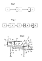
- a treatment line comprises a food pusher 1 receiving as input a raw material or a semi-finished material.
- the pusher 1 outputs a raw food product.
- the line comprises a cooker 2 receiving the raw food products from the pusher 1.
- the cooker 2 is provided with a heat treatment device 4 as described below.
- the cooker 2 outputs a cooked food product.
- the treatment line also comprises a cooler 3.
- the cooler 3 receives the cooked food products from the cooker 2 as input.
- the cooler 3 is here equipped with a heat treatment device 5.
- the heat treatment devices 4 and 5 can be of the same type with heat treatment liquids suitable for baking for the heat treatment device 4 and
- the treatment line may be provided only with the heat treatment device 4 or only with the heat treatment device 5.
- the cooler 3 supplies the food products with a storage temperature at the outlet. The food products can then be stored in a cold room or be subjected to other treatments on other machines not shown.
- the heat treatment line comprises a pusher 1, a pre-cooker 6, a packaging machine 7, a pasteurizer 8 and a cooler 3, arranged in this order.
- the pusher 1 and the cooler 3 may be of the same type as in the previous embodiment.
- the pre-cooker 6 is here provided with a heat treatment device 9.
- the pre-cooker 6 may be of a type similar to the cooker 2 of the embodiment of the invention. figure 1 .
- the pre-cooker 6 can provide a pre-cooking time less than the cooking time by the cooker 2.
- the pre-cooker 6 outputs pre-cooked food products to the packaging machine 7.
- the packaging machine 7 covers said food products with a packaging or packaging ensuring in general a mechanical and bacteriological protection.
- Food products can be packaged individually or in batches.
- the food products can be packaged between two sheets of synthetic material, for example based on polyethylene.
- the packaging machine 7 outputs the packaged food products.
- the pasteurizer 8 is provided with a heat treatment device 10 in order to obtain sufficient pasteurizing values.
- the pasteurizer 8 is configured to meet the standards in force which may require a temperature, a core temperature, or a time at temperature.
- the pasteurizer 8 supplies the conditioned and pasteurized food products having a relatively high temperature.
- the cooler 3 provided with the heat treatment device 5 receives the food products from the pasteurizer 8 and ensures their cooling to a storage temperature.
- the heat treatment devices 9, 10 and 5 of the heat treatment line of the figure 2 may be present in different combinations, of 1, 2 or 3 in said heat treatment line.
- the heat treatment devices 4, 9 and 10 provide treatment by application of heat.
- the heat treatment devices 4, 9 and 10 generally operate with water.
- the heat treatment device 5 provides treatment by application of cold.
- the heat treatment device 5 may operate with water added with salt or other additive allowing the temperature of said brine to drop below 0 ° C.
- the heat treatment device 4 comprises a receptacle 11 and a heat treatment bath 12 disposed downstream of the receptacle 11.
- the receptacle 11 may have a general table shape resting on feet 13.
- the receptacle 11 has a cross section in the general shape of chute.
- the chute includes a bottom and two side walls.
- the receptacle 11 comprises a heat treatment water supply 14 supplying heat treatment water in an upstream portion 14 of said receptacle for a flow towards a downstream portion 15.
- the device comprises a lock 16 disposed downstream of the receptacle 11 in the flow direction of the heat treatment water.
- the heat treatment bath 12 is disposed downstream of the lock 16.
- the heat treatment water is supplied in the upstream portion 14, flows in the downstream portion 15, in the lock 16 and then joins the heat treatment bath 12.
- the heat treatment bath 12 may be at a substantially constant level of heat treatment water.
- the heat treatment bath may comprise an overflow 17 recovering the heat treatment water in excess in said bath 12.
- the overflow 17 may be connected to a pump 18 opening into the heat treatment water supply 14.
- the output of the pump 18 can be directed entirely towards the supply of heat treatment water 14.
- the output of the pump 18 can be directed in part towards the supply of heat treatment water 14 and partly to the heat treatment bath 12 to ensure a stirring of the heat treatment water in the bath 12. A good temperature homogeneity in the bath 12 is obtained.
- the heat treatment bath 12 comprises a tray 19 for heat treatment water open on the top and configured to provide a depth of heat treatment water sufficient for cooking food products and a water temperature sufficiently homogeneous heat treatment.
- the overflow 17 is disposed in or at the edge of the tank 19.
- the overflow 17 is connected to the pump 18 by a pipe 21.
- At the pump 18, may be associated a storage 22 of heat treatment water.
- the storage 22 of heat treatment water may comprise a heating element 23, for example a heat exchanger or an electrical resistance.
- a pipe 24 is mounted between the pump 18 or the storage 22 and the upstream portion 14 of the receptacle 11 and thus send the heat treatment water into the receptacle 11.
- the heat treatment bath 12 also comprises a delay member 20.
- the delay member 20 comprises an endless mechanism.
- the delay member 20 comprises a plurality of vanes 25 transverse to the direction of movement of the food products.
- the pallets 25 are supported at each of their ends by a chain moving in a rail 26. Cogwheels 27 drive the chain in the rail 26.
- the pallets 25 move in an upper part of the path out of the rail. heat treatment water and a lower path portion in contact with the heat treatment water.
- the water level of the tank 19 is substantially constant in order to promote the homogeneity of the temperature.
- the longitudinal ends of the tray 19 are rounded to match the stroke of the corresponding end of the pallets 25 while leaving a small gap between the walls of the tray 19 and the lower ends of the pallets 25.
- pallets are understood to mean lower ends. 25, the end which is in the lower position when the pallet 25 is in contact with the heat treatment water.
- the overflow 17 may be disposed on one of the edges of the tray 19, beyond the pallets 25.
- the pallets 25 are moved in the direction illustrated by the arrow of the figure 3 .
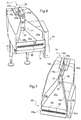
- the receptacle 11 and the lock 16 are illustrated in more detail on the Figures 6 and 7 .
- the upstream portion 14 of the receptacle 11 comprises substantially parallel lateral edges 14a and 14b, a bottom 14c that is substantially horizontal or slopes slightly downstream, an upstream wall 14d and a heat treatment water supply 28.
- the water supply heat treatment unit 28 comprises a plurality of holes arranged in one or more rows aligned vertically and formed in the side walls 14a and 14b near the upstream wall 14d.
- the side walls 14a and 14b may belong to a cassette 29 manipulable by means of a handle 29a and allowing a distribution of the heat treatment water from the pipe 24 to the holes in the side walls 14a and 14b.
- said holes are substantially symmetrical forming a bilateral water supply. This promotes a flow of heat treatment water from upstream to downstream by reducing any areas of stagnation of water heat treatment.
- the upstream portion 14a has a corridor shape, for example narrow and high.
- the dimensions of width and height of the corridor thus formed can be determined by the diameter and the density of the food products to be heat treated. This limits the risk of shock between the food products and the walls of the upstream portion 14.
- the upstream portion 14 also comprises a valve 30 forming downstream wall.
- the valve 30 leaves open a passage forming an outlet 31 for the heat treatment water.
- the outlet 31 is axial in the direction of displacement of the heat treatment water and food products.
- the valve 30 may be adjusted depending on the desired level of heat treatment water in the upstream portion 14 corridor, the diameter of the food products, the desired ejection speed for the food products, etc.
- the outlet 31 has a rectangular shape.
- the valve 30 is in the form of a rectangular piece provided in the upper part with a hole making it easier to grip.
- the height adjustment of the valve 30 can be done manually. Clamping can be obtained by a screw holding the position of said valve 30.
- the downstream portion 15 of the receptacle extends from the valve 30.
- the downstream portion 15 comprises symmetrical and divergent side walls 15a and 15b downstream, and a trapezoidal bottom wall 15c.
- the bottom wall 15c is inclined downstream, in particular at an angle of between 5 ° and 25 °.
- the side walls 15a and 15b are connected to the side walls of the upstream portion 14 by welding or by folding a single sheet.
- the bottom wall 15c is connected to the bottom wall 14c of the upstream portion 14, directly or optionally with a projection 32 forming a threshold.
- the projection 32 has a height of between 1 and 5 cm.
- the projection 32 may be vertical.
- the downstream part 15 joins the lock 16 downstream.
- the lock 16 has side and bottom walls common with the downstream portion 15.
- the lock 15 comprises a tilting door 33.
- the door 33 is pivotally mounted about a substantially horizontal axis. Said axis is disposed at a level slightly lower than the level of the bottom wall 15c. In the open position, the door 33 can be flush with the bottom wall 15c. In the open position, the door 33 is disposed downstream of said tilting axis. In the closed position, the door 33 is straightened upwards, being substantially perpendicular to the bottom wall 15c, see figure 4 .
- the tilting of the door 33, between the open position and the closed position is provided by a motor or a jack arranged in a housing 34 mounted adjacent the downstream portion 15 and the lock 16.
- the door 33 is in the form of a rectangle whose length is disposed transversely to the direction of progression of the heat treatment water and food products. Small sides 33a and 33b of the door 33 are straightened upwards in the closed state. The short sides 33a and 33b are at a distance from the side walls 15a and 15b significantly smaller than the diameter of the food products. The distance can be between 0.5 and 2 mm.
- the open door 33 is disposed with a slope substantially equal to or slightly greater than the slope of the bottom wall 15c of the downstream portion 15. The braking of the heat treatment water passing over the door 33 in the position of opening is thus avoided.
- a plurality of holes 35 are formed in the door 33.
- the holes 35 are arranged in three rows parallel to the length of the door 33.
- the holes 35 are arranged substantially between one-third and two-thirds of the width of said door 33.
- the holes 35 allow the passage of heat treatment water while opposing the passage of food products. This avoids an overflow of the heat treatment water over the upper edge of the door 33 in the closed position, overflow that could lead to food products.
- the door 33 in the closed position comprises a solid lower portion, a perforated intermediate portion and a solid upper portion promoting a sufficient accumulation of heat treatment water to ensure the immersion of food products while avoiding unwanted overflow.
- the heat treatment bath 12 is provided with a sensor 36 for the presence of a pallet 25 at the outlet of the lock 16.
- the sensor 36 may comprise a photocell or a mechanical device.
- the sensor 36 is connected to the motorization housing 34 of the door 33 of the lock 16. In the position illustrated in FIG. figure 4 , a pallet 25 is in front of the sensor 36. The pallet 25 is also in front of the receptacle 11 and the lock 16. Access to the heat treatment bath 12 is therefore not desirable for food products.
- the sensor 36 detects the presence of the pallet 25 and causes, via the motor housing 34, the tilting of the door 33 in the direction illustrated by the arrow of the figure 4 to the closed position.
- the delay member 20 also comprises a pallet 25 in contact with the thermal treatment water of the tank 19 and whose displacement causes the corresponding displacement of the food products present in the heat treatment water upstream of said pallet 25 in front of the sensor 36.
- Another pallet 25 is on the return path out of the heat treatment water.
- the delay member 20 continues its movement.
- the pallet 25 engages in the tray 19, see figure 5 .
- the sensor 36 is released from the pallet 25 and controls via the motorization box 34 the tilting of the door 33 in the direction illustrated by the arrow of the figure 5 .
- the door 33 is here illustrated in an advanced tilting position, close enough to the open position. In the position As shown, the accumulated water already begins to flow over the door 33. The food products follow the movement of the heat treatment water. We reach the open position illustrated on the figure 3 .
- the door 33 is then open, in a position substantially aligned with the bottom 15c of the downstream portion 15, or even with a slightly greater slope to prevent slowing of the heat treatment water and food products. Access to the tray 19 is free.
- the sensor 36 is clear.
- a pallet 25 is already engaged in the tray 19 on a horizontal portion of its trajectory corresponding to a horizontal portion of the rail 26.
- the following pallet 25 continues its return trajectory on a downward oblique portion of the rail 26.
- the following pallet 25 does not interfere not moving the food products from the receptacle 11 and the lock 16 in the tray 19.
- the receptacle 11 and the lock 16 are provided with bottom and side walls sealed so that the heat treatment water injected by the feed 28 flows into the tray 19.
- the receptacle 11 and the lock 16 can be covered by covers 37 for good thermal insulation and protection of food products.
- the receptacle 11 has a substantially continuous operation with a continuous water supply and a food supply at a high rate, for example greater than 200 units per minute.
- the lock 16 allows a momentary interruption, for example for a few seconds, of the feeding of the heat-treatment bath 12 with food products, allowing time for a pallet to clear an entrance space of food products into the bath of food. heat treatment 12.
- the pallets 25 may be moving at a constant speed.
- the level of heat treatment water in the upstream portion 14 is determined by the water supply 28, and the position of the valve 30. This allows to receive food products from the top by limiting the risk of shock and deterioration the envelope of the food product. Furthermore, the food product falling in the heat treatment water of the upstream part tends to remain close to the bottom wall 14c because of the streams of water heading towards the outlet 31. However, it may happen that some food products, especially elongated, turn in the upstream portion 14. It is interesting to provide an output 31 of sufficient size to let two food products at the same time. Once past exit 31, the food products accelerate because of the slight drop caused by the presence of the projection which provides a difference in level between the bottom 14c and the bottom 15c and on the other hand by the inclination of the bottom 15c .
- the heat treatment water then tends to accelerate and spread over the increasing width of the downstream portion 15.
- the food products deviate from each other due to the acceleration of the heat treatment water and are also distributed over the increasing width of the downstream portion 15.
- the food products are brought directly by the heat treatment water into the heat treatment bath 12.
- the food products are already spread over a significant width of the tank as they enter the bath.
- the closed position of the lock 16 the food products are temporarily stored upstream of the door 33 with a basin formed by the heat treatment water held by said door 33.
Landscapes
- Life Sciences & Earth Sciences (AREA)
- Engineering & Computer Science (AREA)
- Wood Science & Technology (AREA)
- Zoology (AREA)
- Chemical & Material Sciences (AREA)
- Food Science & Technology (AREA)
- Polymers & Plastics (AREA)
- General Preparation And Processing Of Foods (AREA)
- Commercial Cooking Devices (AREA)
- Food Preservation Except Freezing, Refrigeration, And Drying (AREA)
- Meat, Egg Or Seafood Products (AREA)
- Beans For Foods Or Fodder (AREA)
Applications Claiming Priority (1)
| Application Number | Priority Date | Filing Date | Title |
|---|---|---|---|
| FR1004909A FR2968894B1 (fr) | 2010-12-15 | 2010-12-15 | Dispositif et procede de traitement thermique de produits alimentaires |
Publications (2)
| Publication Number | Publication Date |
|---|---|
| EP2465355A1 true EP2465355A1 (de) | 2012-06-20 |
| EP2465355B1 EP2465355B1 (de) | 2014-11-05 |
Family
ID=45524303
Family Applications (1)
| Application Number | Title | Priority Date | Filing Date |
|---|---|---|---|
| EP11290581.5A Active EP2465355B1 (de) | 2010-12-15 | 2011-12-15 | Vorrichtung und Verfahren zur Wärmebehandlung von Lebensmitteln |
Country Status (8)
| Country | Link |
|---|---|
| US (1) | US20120156348A1 (de) |
| EP (1) | EP2465355B1 (de) |
| JP (1) | JP2012125244A (de) |
| BR (1) | BRPI1105205A2 (de) |
| CA (1) | CA2761224A1 (de) |
| ES (1) | ES2529685T3 (de) |
| FR (1) | FR2968894B1 (de) |
| MX (1) | MX2011013677A (de) |
Citations (9)
| Publication number | Priority date | Publication date | Assignee | Title |
|---|---|---|---|---|
| FR1095351A (fr) * | 1953-10-27 | 1955-06-01 | Procédé et appareil pour la cuisson des conserves | |
| GB895101A (en) | 1958-09-11 | 1962-05-02 | Paul Helmut Hilgeland | Improvements in or relating to methods for preparing sausages or the like |
| US3700847A (en) | 1970-07-06 | 1972-10-24 | Armour & Co | System for continuous processing of vienna sausage using microwave energy |
| US3761290A (en) | 1971-02-17 | 1973-09-25 | Manning S Inc | Food cooking apparatus |
| DE2228564A1 (de) | 1972-06-12 | 1974-01-10 | Ascobloc Veb K | Vorrichtung zum kontinuierlichen garen, kochen und daempfen oder kuehlen von lebensmitteln |
| EP0234068A1 (de) | 1986-02-14 | 1987-09-02 | The Dow Chemical Company | Aufbereitungsverfahren für Kohle |
| FR2691881A1 (fr) * | 1992-06-05 | 1993-12-10 | Cirad Sar | Procédé et dispositif de brassage mixte hydraulique-mécanique pour la déshydratation-imprégnation de produits alimentaires fractionnés. |
| US20080279990A1 (en) | 2001-02-01 | 2008-11-13 | Stork Townsend Bv | Method and device for producing and packaging sausage type products |
| US20090004346A1 (en) * | 2007-06-29 | 2009-01-01 | Estes Jeremy B | Continuous vacuum marination apparatus and method |
Family Cites Families (23)
| Publication number | Priority date | Publication date | Assignee | Title |
|---|---|---|---|---|
| US229901A (en) * | 1880-07-13 | Apparatus for cleaning and dampening grain | ||
| US757186A (en) * | 1903-03-19 | 1904-04-12 | Rosman I Fancher | Apparatus for scalding and washing fruits and vegetables. |
| US1559733A (en) * | 1925-02-21 | 1925-11-03 | William R Barger | Apparatus for the treatment of fruit with antiseptics for the prevention of decay |
| US2039276A (en) * | 1934-11-14 | 1936-05-05 | Ayars Machine Co | Fruit and vegetable washer |
| US2249792A (en) * | 1938-08-05 | 1941-07-22 | Bronson C Skinner | Method and apparatus for treating fruit |
| US3322173A (en) * | 1964-05-26 | 1967-05-30 | Borden Co | Apparatus for washing and peeling fruits and vegetables |
| US3498208A (en) * | 1965-03-01 | 1970-03-03 | Int Agri Systems | Heat exchange apparatus |
| US4169409A (en) * | 1978-04-05 | 1979-10-02 | Haubner James W | Food processing equipment |
| US4234612A (en) * | 1978-11-24 | 1980-11-18 | Sakuichi Sakakibara | Continuous frying method |
| US4569200A (en) * | 1984-05-14 | 1986-02-11 | Lamb Carl W | Control apparatus for tidal turbine |
| US4744293A (en) * | 1986-12-30 | 1988-05-17 | Sun Plant Industry Co., Ltd. | Automatic continuous food frying device |
| US4867049A (en) * | 1988-03-07 | 1989-09-19 | Mike Sell's Potato Chip Co. | Food product precooking method and apparatus |
| JPH01178827U (de) * | 1988-06-06 | 1989-12-21 | ||
| US5141762A (en) * | 1989-08-29 | 1992-08-25 | Oscar Mayer Foods Corporation | Apparatus and method for forming casingless sausage and the like |
| US5666876A (en) * | 1991-12-20 | 1997-09-16 | Vos Industries Ltd. | Cooking apparatus |
| US5322006A (en) * | 1992-03-31 | 1994-06-21 | House Food Industrial Co., Ltd. | Continuous frying apparatus |
| US5253567A (en) * | 1993-03-05 | 1993-10-19 | Stein, Inc. | Thermal fluid heat exchanger for deep fat fryer |
| US5843504A (en) * | 1996-10-15 | 1998-12-01 | Townsend Engineering Company | Method and apparatus for coagulating the outer surface of a sausage strand discharged from a sausage extruding machine |
| US5937877A (en) * | 1997-09-23 | 1999-08-17 | Rodriguez; Jeffrey J. | Apparatus for washing foodstuffs |
| US6263785B1 (en) * | 1998-06-09 | 2001-07-24 | David R. Zittel | Blancher and method of operation |
| WO2001013772A1 (fr) * | 1999-08-25 | 2001-03-01 | House Foods Corporation | Dispositif de traitement continu |
| AU2001246912A1 (en) * | 2000-04-25 | 2001-11-07 | Shinko Plant Construction Co., Ltd. | Device for cleaning food with ozone water, and method of cleaning food using cleaning device |
| CA2430635A1 (en) * | 2003-06-02 | 2004-12-02 | Charlottetown Metal Products | Continuous flow pressurized cooker/blancher |
-
2010
- 2010-12-15 FR FR1004909A patent/FR2968894B1/fr active Active
-
2011
- 2011-04-04 US US13/079,311 patent/US20120156348A1/en not_active Abandoned
- 2011-12-06 CA CA2761224A patent/CA2761224A1/fr not_active Abandoned
- 2011-12-14 JP JP2011273457A patent/JP2012125244A/ja active Pending
- 2011-12-15 ES ES11290581.5T patent/ES2529685T3/es active Active
- 2011-12-15 EP EP11290581.5A patent/EP2465355B1/de active Active
- 2011-12-15 BR BRPI1105205-8A patent/BRPI1105205A2/pt active Search and Examination
- 2011-12-15 MX MX2011013677A patent/MX2011013677A/es active IP Right Grant
Patent Citations (9)
| Publication number | Priority date | Publication date | Assignee | Title |
|---|---|---|---|---|
| FR1095351A (fr) * | 1953-10-27 | 1955-06-01 | Procédé et appareil pour la cuisson des conserves | |
| GB895101A (en) | 1958-09-11 | 1962-05-02 | Paul Helmut Hilgeland | Improvements in or relating to methods for preparing sausages or the like |
| US3700847A (en) | 1970-07-06 | 1972-10-24 | Armour & Co | System for continuous processing of vienna sausage using microwave energy |
| US3761290A (en) | 1971-02-17 | 1973-09-25 | Manning S Inc | Food cooking apparatus |
| DE2228564A1 (de) | 1972-06-12 | 1974-01-10 | Ascobloc Veb K | Vorrichtung zum kontinuierlichen garen, kochen und daempfen oder kuehlen von lebensmitteln |
| EP0234068A1 (de) | 1986-02-14 | 1987-09-02 | The Dow Chemical Company | Aufbereitungsverfahren für Kohle |
| FR2691881A1 (fr) * | 1992-06-05 | 1993-12-10 | Cirad Sar | Procédé et dispositif de brassage mixte hydraulique-mécanique pour la déshydratation-imprégnation de produits alimentaires fractionnés. |
| US20080279990A1 (en) | 2001-02-01 | 2008-11-13 | Stork Townsend Bv | Method and device for producing and packaging sausage type products |
| US20090004346A1 (en) * | 2007-06-29 | 2009-01-01 | Estes Jeremy B | Continuous vacuum marination apparatus and method |
Also Published As
| Publication number | Publication date |
|---|---|
| FR2968894B1 (fr) | 2013-01-18 |
| FR2968894A1 (fr) | 2012-06-22 |
| MX2011013677A (es) | 2012-06-14 |
| EP2465355B1 (de) | 2014-11-05 |
| CA2761224A1 (fr) | 2012-06-15 |
| US20120156348A1 (en) | 2012-06-21 |
| JP2012125244A (ja) | 2012-07-05 |
| ES2529685T3 (es) | 2015-02-24 |
| BRPI1105205A2 (pt) | 2013-04-09 |
Similar Documents
| Publication | Publication Date | Title |
|---|---|---|
| EP1978855A1 (de) | Kochvorrichtung mit rührmittel und entsprechendes verfahren | |
| EP0242287A1 (de) | Anlage zum Bereiten von Fertigmahlzeiten | |
| EP0070228A2 (de) | Verfahren zum Kochen von Schinken | |
| RU2573759C2 (ru) | Способ и устройство для соусирования сушеных орехов посредством диффузии посредством соления, сахаризации или ароматизации | |
| US4600596A (en) | Automatic food cooking machine | |
| EP2465355B1 (de) | Vorrichtung und Verfahren zur Wärmebehandlung von Lebensmitteln | |
| FR2937501A1 (fr) | Dispositif de conservation, de cuisson et de distribution automatique de produits a base de pate, notamment de pains | |
| WO2008073320A3 (en) | Angled conveyor for return toaster | |
| JP2020120645A (ja) | 麺取り装置 | |
| EP1110042A1 (de) | Verfahren und vorrichtung zur kontinuierlichen kühlung von nahrungsmitteln | |
| EP0601952B1 (de) | Verfahren zur thermischen Behandlung von Nahrungsmitteln, insbesondere zum Kochen von Gemüse und Anlage zur Durchführung des Verfahrens | |
| WO2006000703A1 (fr) | Dispositif de traitement de produits alimentaires dans un bain de liquide | |
| FR3135712A3 (fr) | « tunnel cryogénique avec convoyeur pour réalisation de dosettes de produits alimentaires, notamment de sauce» | |
| EP0085426A1 (de) | Semi-kontinuierliches Verfahren zur Herstellung eines Nahrungsmittelgemisches und Vorrichtung zur Durchführung des Verfahrens | |
| WO2011107496A1 (fr) | Dispositif de traitement thermique de saucisses du type saucisses co-extrudées | |
| EP2988612B1 (de) | Verfahren und vorrichtung zum erhalt von in einem behälter verpackten lebensmitteln mit einer markierung für gegrilltes aussehen | |
| TWM555037U (zh) | 用於食品販賣機的烹調裝置 | |
| EP2147605B1 (de) | Anlage und Verfahren zur kontinuierlichen Behandlung eines zum Verzehr bedingten Produkts, insbesondere eines Lebensmittelprodukts | |
| TWI634520B (zh) | Cooking device for food vending machine | |
| FR2471143A1 (fr) | Machine pour la fabrication d'articles de patisserie en pate cuite | |
| FR2647639A1 (fr) | Procede et dispositif pour le traitement thermique, notamment la cuisson de produits fragiles tels que des preparations alimentaires | |
| FR2664683A1 (fr) | Dispositif d'echange thermique en vue de porter un produit a une temperature predeterminee. | |
| EP2820960A1 (de) | Fritteuse | |
| FR2581838A1 (fr) | Installation de cuisson en continu de produits alimentaires | |
| WO2017153671A1 (fr) | Installation de production industrielle de produits de boulangerie, viennoiserie, patisserie ou similaires et procede correspondant |
Legal Events
| Date | Code | Title | Description |
|---|---|---|---|
| PUAI | Public reference made under article 153(3) epc to a published international application that has entered the european phase |
Free format text: ORIGINAL CODE: 0009012 |
|
| AK | Designated contracting states |
Kind code of ref document: A1 Designated state(s): AL AT BE BG CH CY CZ DE DK EE ES FI FR GB GR HR HU IE IS IT LI LT LU LV MC MK MT NL NO PL PT RO RS SE SI SK SM TR |
|
| AX | Request for extension of the european patent |
Extension state: BA ME |
|
| 17P | Request for examination filed |
Effective date: 20121114 |
|
| GRAP | Despatch of communication of intention to grant a patent |
Free format text: ORIGINAL CODE: EPIDOSNIGR1 |
|
| INTG | Intention to grant announced |
Effective date: 20140710 |
|
| GRAS | Grant fee paid |
Free format text: ORIGINAL CODE: EPIDOSNIGR3 |
|
| GRAA | (expected) grant |
Free format text: ORIGINAL CODE: 0009210 |
|
| AK | Designated contracting states |
Kind code of ref document: B1 Designated state(s): AL AT BE BG CH CY CZ DE DK EE ES FI FR GB GR HR HU IE IS IT LI LT LU LV MC MK MT NL NO PL PT RO RS SE SI SK SM TR |
|
| REG | Reference to a national code |
Ref country code: GB Ref legal event code: FG4D Free format text: NOT ENGLISH |
|
| REG | Reference to a national code |
Ref country code: CH Ref legal event code: EP |
|
| REG | Reference to a national code |
Ref country code: AT Ref legal event code: REF Ref document number: 694092 Country of ref document: AT Kind code of ref document: T Effective date: 20141115 |
|
| REG | Reference to a national code |
Ref country code: IE Ref legal event code: FG4D Free format text: LANGUAGE OF EP DOCUMENT: FRENCH |
|
| REG | Reference to a national code |
Ref country code: DE Ref legal event code: R096 Ref document number: 602011011075 Country of ref document: DE Effective date: 20141224 |
|
| REG | Reference to a national code |
Ref country code: ES Ref legal event code: FG2A Ref document number: 2529685 Country of ref document: ES Kind code of ref document: T3 Effective date: 20150224 |
|
| REG | Reference to a national code |
Ref country code: AT Ref legal event code: MK05 Ref document number: 694092 Country of ref document: AT Kind code of ref document: T Effective date: 20141105 |
|
| REG | Reference to a national code |
Ref country code: NL Ref legal event code: VDEP Effective date: 20141105 |
|
| REG | Reference to a national code |
Ref country code: LT Ref legal event code: MG4D |
|
| PG25 | Lapsed in a contracting state [announced via postgrant information from national office to epo] |
Ref country code: FI Free format text: LAPSE BECAUSE OF FAILURE TO SUBMIT A TRANSLATION OF THE DESCRIPTION OR TO PAY THE FEE WITHIN THE PRESCRIBED TIME-LIMIT Effective date: 20141105 Ref country code: LT Free format text: LAPSE BECAUSE OF FAILURE TO SUBMIT A TRANSLATION OF THE DESCRIPTION OR TO PAY THE FEE WITHIN THE PRESCRIBED TIME-LIMIT Effective date: 20141105 Ref country code: NL Free format text: LAPSE BECAUSE OF FAILURE TO SUBMIT A TRANSLATION OF THE DESCRIPTION OR TO PAY THE FEE WITHIN THE PRESCRIBED TIME-LIMIT Effective date: 20141105 Ref country code: IS Free format text: LAPSE BECAUSE OF FAILURE TO SUBMIT A TRANSLATION OF THE DESCRIPTION OR TO PAY THE FEE WITHIN THE PRESCRIBED TIME-LIMIT Effective date: 20150305 Ref country code: NO Free format text: LAPSE BECAUSE OF FAILURE TO SUBMIT A TRANSLATION OF THE DESCRIPTION OR TO PAY THE FEE WITHIN THE PRESCRIBED TIME-LIMIT Effective date: 20150205 Ref country code: PT Free format text: LAPSE BECAUSE OF FAILURE TO SUBMIT A TRANSLATION OF THE DESCRIPTION OR TO PAY THE FEE WITHIN THE PRESCRIBED TIME-LIMIT Effective date: 20150305 |
|
| PG25 | Lapsed in a contracting state [announced via postgrant information from national office to epo] |
Ref country code: LV Free format text: LAPSE BECAUSE OF FAILURE TO SUBMIT A TRANSLATION OF THE DESCRIPTION OR TO PAY THE FEE WITHIN THE PRESCRIBED TIME-LIMIT Effective date: 20141105 Ref country code: GR Free format text: LAPSE BECAUSE OF FAILURE TO SUBMIT A TRANSLATION OF THE DESCRIPTION OR TO PAY THE FEE WITHIN THE PRESCRIBED TIME-LIMIT Effective date: 20150206 Ref country code: AT Free format text: LAPSE BECAUSE OF FAILURE TO SUBMIT A TRANSLATION OF THE DESCRIPTION OR TO PAY THE FEE WITHIN THE PRESCRIBED TIME-LIMIT Effective date: 20141105 Ref country code: PL Free format text: LAPSE BECAUSE OF FAILURE TO SUBMIT A TRANSLATION OF THE DESCRIPTION OR TO PAY THE FEE WITHIN THE PRESCRIBED TIME-LIMIT Effective date: 20141105 Ref country code: SE Free format text: LAPSE BECAUSE OF FAILURE TO SUBMIT A TRANSLATION OF THE DESCRIPTION OR TO PAY THE FEE WITHIN THE PRESCRIBED TIME-LIMIT Effective date: 20141105 Ref country code: CY Free format text: LAPSE BECAUSE OF FAILURE TO SUBMIT A TRANSLATION OF THE DESCRIPTION OR TO PAY THE FEE WITHIN THE PRESCRIBED TIME-LIMIT Effective date: 20141105 Ref country code: HR Free format text: LAPSE BECAUSE OF FAILURE TO SUBMIT A TRANSLATION OF THE DESCRIPTION OR TO PAY THE FEE WITHIN THE PRESCRIBED TIME-LIMIT Effective date: 20141105 Ref country code: RS Free format text: LAPSE BECAUSE OF FAILURE TO SUBMIT A TRANSLATION OF THE DESCRIPTION OR TO PAY THE FEE WITHIN THE PRESCRIBED TIME-LIMIT Effective date: 20141105 |
|
| PG25 | Lapsed in a contracting state [announced via postgrant information from national office to epo] |
Ref country code: BE Free format text: LAPSE BECAUSE OF NON-PAYMENT OF DUE FEES Effective date: 20141231 |
|
| REG | Reference to a national code |
Ref country code: DE Ref legal event code: R119 Ref document number: 602011011075 Country of ref document: DE |
|
| PG25 | Lapsed in a contracting state [announced via postgrant information from national office to epo] |
Ref country code: DK Free format text: LAPSE BECAUSE OF FAILURE TO SUBMIT A TRANSLATION OF THE DESCRIPTION OR TO PAY THE FEE WITHIN THE PRESCRIBED TIME-LIMIT Effective date: 20141105 Ref country code: EE Free format text: LAPSE BECAUSE OF FAILURE TO SUBMIT A TRANSLATION OF THE DESCRIPTION OR TO PAY THE FEE WITHIN THE PRESCRIBED TIME-LIMIT Effective date: 20141105 Ref country code: SK Free format text: LAPSE BECAUSE OF FAILURE TO SUBMIT A TRANSLATION OF THE DESCRIPTION OR TO PAY THE FEE WITHIN THE PRESCRIBED TIME-LIMIT Effective date: 20141105 Ref country code: CZ Free format text: LAPSE BECAUSE OF FAILURE TO SUBMIT A TRANSLATION OF THE DESCRIPTION OR TO PAY THE FEE WITHIN THE PRESCRIBED TIME-LIMIT Effective date: 20141105 |
|
| REG | Reference to a national code |
Ref country code: CH Ref legal event code: PL |
|
| PG25 | Lapsed in a contracting state [announced via postgrant information from national office to epo] |
Ref country code: MC Free format text: LAPSE BECAUSE OF FAILURE TO SUBMIT A TRANSLATION OF THE DESCRIPTION OR TO PAY THE FEE WITHIN THE PRESCRIBED TIME-LIMIT Effective date: 20141105 |
|
| PLBE | No opposition filed within time limit |
Free format text: ORIGINAL CODE: 0009261 |
|
| STAA | Information on the status of an ep patent application or granted ep patent |
Free format text: STATUS: NO OPPOSITION FILED WITHIN TIME LIMIT |
|
| REG | Reference to a national code |
Ref country code: IE Ref legal event code: MM4A |
|
| 26N | No opposition filed |
Effective date: 20150806 |
|
| PG25 | Lapsed in a contracting state [announced via postgrant information from national office to epo] |
Ref country code: CH Free format text: LAPSE BECAUSE OF NON-PAYMENT OF DUE FEES Effective date: 20141231 Ref country code: DE Free format text: LAPSE BECAUSE OF NON-PAYMENT OF DUE FEES Effective date: 20150701 Ref country code: IE Free format text: LAPSE BECAUSE OF NON-PAYMENT OF DUE FEES Effective date: 20141215 Ref country code: LI Free format text: LAPSE BECAUSE OF NON-PAYMENT OF DUE FEES Effective date: 20141231 |
|
| REG | Reference to a national code |
Ref country code: FR Ref legal event code: PLFP Year of fee payment: 5 |
|
| PG25 | Lapsed in a contracting state [announced via postgrant information from national office to epo] |
Ref country code: SI Free format text: LAPSE BECAUSE OF FAILURE TO SUBMIT A TRANSLATION OF THE DESCRIPTION OR TO PAY THE FEE WITHIN THE PRESCRIBED TIME-LIMIT Effective date: 20141105 |
|
| PG25 | Lapsed in a contracting state [announced via postgrant information from national office to epo] |
Ref country code: SM Free format text: LAPSE BECAUSE OF FAILURE TO SUBMIT A TRANSLATION OF THE DESCRIPTION OR TO PAY THE FEE WITHIN THE PRESCRIBED TIME-LIMIT Effective date: 20141105 |
|
| PG25 | Lapsed in a contracting state [announced via postgrant information from national office to epo] |
Ref country code: RO Free format text: LAPSE BECAUSE OF FAILURE TO SUBMIT A TRANSLATION OF THE DESCRIPTION OR TO PAY THE FEE WITHIN THE PRESCRIBED TIME-LIMIT Effective date: 20141105 |
|
| PG25 | Lapsed in a contracting state [announced via postgrant information from national office to epo] |
Ref country code: BG Free format text: LAPSE BECAUSE OF FAILURE TO SUBMIT A TRANSLATION OF THE DESCRIPTION OR TO PAY THE FEE WITHIN THE PRESCRIBED TIME-LIMIT Effective date: 20141105 |
|
| PG25 | Lapsed in a contracting state [announced via postgrant information from national office to epo] |
Ref country code: HU Free format text: LAPSE BECAUSE OF FAILURE TO SUBMIT A TRANSLATION OF THE DESCRIPTION OR TO PAY THE FEE WITHIN THE PRESCRIBED TIME-LIMIT; INVALID AB INITIO Effective date: 20111215 Ref country code: MT Free format text: LAPSE BECAUSE OF FAILURE TO SUBMIT A TRANSLATION OF THE DESCRIPTION OR TO PAY THE FEE WITHIN THE PRESCRIBED TIME-LIMIT Effective date: 20141105 Ref country code: TR Free format text: LAPSE BECAUSE OF FAILURE TO SUBMIT A TRANSLATION OF THE DESCRIPTION OR TO PAY THE FEE WITHIN THE PRESCRIBED TIME-LIMIT Effective date: 20141105 Ref country code: LU Free format text: LAPSE BECAUSE OF NON-PAYMENT OF DUE FEES Effective date: 20141215 |
|
| GBPC | Gb: european patent ceased through non-payment of renewal fee |
Effective date: 20151215 |
|
| PG25 | Lapsed in a contracting state [announced via postgrant information from national office to epo] |
Ref country code: GB Free format text: LAPSE BECAUSE OF NON-PAYMENT OF DUE FEES Effective date: 20151215 |
|
| REG | Reference to a national code |
Ref country code: FR Ref legal event code: PLFP Year of fee payment: 6 |
|
| REG | Reference to a national code |
Ref country code: FR Ref legal event code: PLFP Year of fee payment: 7 |
|
| PG25 | Lapsed in a contracting state [announced via postgrant information from national office to epo] |
Ref country code: MK Free format text: LAPSE BECAUSE OF FAILURE TO SUBMIT A TRANSLATION OF THE DESCRIPTION OR TO PAY THE FEE WITHIN THE PRESCRIBED TIME-LIMIT Effective date: 20141105 |
|
| PG25 | Lapsed in a contracting state [announced via postgrant information from national office to epo] |
Ref country code: AL Free format text: LAPSE BECAUSE OF FAILURE TO SUBMIT A TRANSLATION OF THE DESCRIPTION OR TO PAY THE FEE WITHIN THE PRESCRIBED TIME-LIMIT Effective date: 20141105 |
|
| PGFP | Annual fee paid to national office [announced via postgrant information from national office to epo] |
Ref country code: IT Payment date: 20251223 Year of fee payment: 15 |
|
| PGFP | Annual fee paid to national office [announced via postgrant information from national office to epo] |
Ref country code: FR Payment date: 20251222 Year of fee payment: 15 |
|
| PGFP | Annual fee paid to national office [announced via postgrant information from national office to epo] |
Ref country code: ES Payment date: 20260130 Year of fee payment: 15 |