EP2465572A2 - Fil implantable compatible avec l'IRM - Google Patents
Fil implantable compatible avec l'IRM Download PDFInfo
- Publication number
- EP2465572A2 EP2465572A2 EP11191738A EP11191738A EP2465572A2 EP 2465572 A2 EP2465572 A2 EP 2465572A2 EP 11191738 A EP11191738 A EP 11191738A EP 11191738 A EP11191738 A EP 11191738A EP 2465572 A2 EP2465572 A2 EP 2465572A2
- Authority
- EP
- European Patent Office
- Prior art keywords
- conductor
- medical device
- function
- double
- electrode
- Prior art date
- Legal status (The legal status is an assumption and is not a legal conclusion. Google has not performed a legal analysis and makes no representation as to the accuracy of the status listed.)
- Granted
Links
- 239000004020 conductor Substances 0.000 claims abstract description 103
- 238000002560 therapeutic procedure Methods 0.000 claims abstract description 16
- 230000008878 coupling Effects 0.000 claims abstract description 12
- 238000010168 coupling process Methods 0.000 claims abstract description 12
- 238000005859 coupling reaction Methods 0.000 claims abstract description 12
- 230000002238 attenuated effect Effects 0.000 claims abstract description 4
- 230000004888 barrier function Effects 0.000 claims description 21
- 230000000747 cardiac effect Effects 0.000 claims description 11
- 229920000106 Liquid crystal polymer Polymers 0.000 claims description 4
- 239000004977 Liquid-crystal polymers (LCPs) Substances 0.000 claims description 4
- 238000009413 insulation Methods 0.000 claims description 4
- 230000005540 biological transmission Effects 0.000 claims description 2
- 229920001940 conductive polymer Polymers 0.000 claims description 2
- 238000001465 metallisation Methods 0.000 claims description 2
- 241000906446 Theraps Species 0.000 claims 1
- 230000001225 therapeutic effect Effects 0.000 abstract description 8
- 239000003989 dielectric material Substances 0.000 abstract 1
- 239000003990 capacitor Substances 0.000 description 12
- 238000010586 diagram Methods 0.000 description 7
- 238000002595 magnetic resonance imaging Methods 0.000 description 7
- 210000001519 tissue Anatomy 0.000 description 7
- 230000000694 effects Effects 0.000 description 5
- 230000000638 stimulation Effects 0.000 description 5
- 230000001419 dependent effect Effects 0.000 description 3
- 238000005516 engineering process Methods 0.000 description 3
- 210000005003 heart tissue Anatomy 0.000 description 3
- 238000010438 heat treatment Methods 0.000 description 3
- 238000003384 imaging method Methods 0.000 description 3
- 239000002184 metal Substances 0.000 description 3
- 210000005241 right ventricle Anatomy 0.000 description 3
- 230000002861 ventricular Effects 0.000 description 3
- 238000010792 warming Methods 0.000 description 3
- 238000010276 construction Methods 0.000 description 2
- 239000007943 implant Substances 0.000 description 2
- 238000009434 installation Methods 0.000 description 2
- 210000004165 myocardium Anatomy 0.000 description 2
- 238000004088 simulation Methods 0.000 description 2
- 238000004611 spectroscopical analysis Methods 0.000 description 2
- 235000013599 spices Nutrition 0.000 description 2
- 229910000859 α-Fe Inorganic materials 0.000 description 2
- 238000002679 ablation Methods 0.000 description 1
- 230000001143 conditioned effect Effects 0.000 description 1
- 238000006073 displacement reaction Methods 0.000 description 1
- 230000009977 dual effect Effects 0.000 description 1
- 230000002500 effect on skin Effects 0.000 description 1
- 230000005684 electric field Effects 0.000 description 1
- 238000004070 electrodeposition Methods 0.000 description 1
- WABPQHHGFIMREM-UHFFFAOYSA-N lead(0) Chemical compound [Pb] WABPQHHGFIMREM-UHFFFAOYSA-N 0.000 description 1
- 210000005240 left ventricle Anatomy 0.000 description 1
- 238000000034 method Methods 0.000 description 1
- 238000005457 optimization Methods 0.000 description 1
- 230000003071 parasitic effect Effects 0.000 description 1
- 230000010363 phase shift Effects 0.000 description 1
- 230000009467 reduction Effects 0.000 description 1
- 230000004044 response Effects 0.000 description 1
- 210000005245 right atrium Anatomy 0.000 description 1
- 230000003068 static effect Effects 0.000 description 1
- 238000007740 vapor deposition Methods 0.000 description 1
- 238000004804 winding Methods 0.000 description 1
Images





Classifications
-
- A—HUMAN NECESSITIES
- A61—MEDICAL OR VETERINARY SCIENCE; HYGIENE
- A61N—ELECTROTHERAPY; MAGNETOTHERAPY; RADIATION THERAPY; ULTRASOUND THERAPY
- A61N1/00—Electrotherapy; Circuits therefor
- A61N1/02—Details
- A61N1/04—Electrodes
- A61N1/05—Electrodes for implantation or insertion into the body, e.g. heart electrode
-
- A—HUMAN NECESSITIES
- A61—MEDICAL OR VETERINARY SCIENCE; HYGIENE
- A61B—DIAGNOSIS; SURGERY; IDENTIFICATION
- A61B18/00—Surgical instruments, devices or methods for transferring non-mechanical forms of energy to or from the body
- A61B18/04—Surgical instruments, devices or methods for transferring non-mechanical forms of energy to or from the body by heating
- A61B18/12—Surgical instruments, devices or methods for transferring non-mechanical forms of energy to or from the body by heating by passing a current through the tissue to be heated, e.g. high-frequency current
- A61B18/14—Probes or electrodes therefor
- A61B18/1492—Probes or electrodes therefor having a flexible, catheter-like structure, e.g. for heart ablation
-
- A—HUMAN NECESSITIES
- A61—MEDICAL OR VETERINARY SCIENCE; HYGIENE
- A61N—ELECTROTHERAPY; MAGNETOTHERAPY; RADIATION THERAPY; ULTRASOUND THERAPY
- A61N1/00—Electrotherapy; Circuits therefor
- A61N1/02—Details
- A61N1/04—Electrodes
- A61N1/05—Electrodes for implantation or insertion into the body, e.g. heart electrode
- A61N1/056—Transvascular endocardial electrode systems
-
- A—HUMAN NECESSITIES
- A61—MEDICAL OR VETERINARY SCIENCE; HYGIENE
- A61N—ELECTROTHERAPY; MAGNETOTHERAPY; RADIATION THERAPY; ULTRASOUND THERAPY
- A61N1/00—Electrotherapy; Circuits therefor
- A61N1/02—Details
- A61N1/08—Arrangements or circuits for monitoring, protecting, controlling or indicating
- A61N1/086—Magnetic resonance imaging [MRI] compatible leads
Definitions
- the invention relates to a permanently or temporarily implantable device with an elongated electrical conductor.
- Such devices for example electrode lines for electrostimulation or catheters for electrophysiological interventions, have the disadvantage that their electrical conductor can heat up in a magnetic resonance tomograph because the magnetic fields prevailing in the magnetic resonance tomograph induce not inconsiderable electrical currents in the electrical conductor. Also, such induced currents can be delivered via electrode poles of the electrode line to surrounding tissue and thus, for example, lead to undesired tissue warming. Therefore, cardiac pacemaker patients today can usually not be examined or only to a limited extent in a magnetic resonance tomograph.
- At least one stimulation electrode lead which has a standardized electrical connection at its proximal end provided for connection to the pacemaker or defibrillator, is typically connected to implantable cardiac pacemakers or defibrillators (also collectively referred to as cardiac stimulators or implantable pulse generators) has one or more electrode poles at its distal end provided for placement in the heart.
- implantable cardiac pacemakers or defibrillators also collectively referred to as cardiac stimulators or implantable pulse generators
- Such an electrode pole serves to deliver electrical impulses to the tissue (myocardium) of the heart or to sense electric fields in order to be able to sense an activity of a heart within the scope of so-called sensing.
- electrode poles typically form electrically conductive surface portions of an electrode lead.
- Electrode poles are typically a ring electrode in the form of a ring around the electrode lead or in the form of a tip or tip electrode at the distal end of the electrode lead intended.
- the electrode poles are electrically conductively connected via one or more electrical conductors to contacts of the electrical connection of the electrode line at its proximal end.
- the electrode leads extend at their proximal end and the electrode poles at the distal end of the electrode lead one or more electrical conductors electrically connecting one or more of the electrode poles to one or more of the contacts.
- These electrical conductors can be used, on the one hand, to transmit stimulation pulses to the electrode poles and, on the other hand, to transmit electrical signals picked up by the electrode poles to the proximal end of the electrode lead and are also referred to as function leads in the course of the further description.
- function lines are required for the functions of the respective electrode line electrical conductors and as such the risk that in them by external alternating magnetic fields electrical currents are induced, which can lead, for example, to an undesirable heating of the function lines or connected to her electrode poles or the delivery corresponding currents can lead to the surrounding tissue via the electrode poles and thus to a heating of the surrounding tissue.
- the invention has for its object to provide a device which solves the problem described above.
- this object is achieved by a temporary or permanently implantable medical device with at least one elongated electrical functional conductor for the transmission of therapy signals or diagnostic signals or both, wherein at least one additional conductor is provided, which together with the function conductor at least partially forms a double line, of the functional conductor a dielectric is separated and which is coupled to the functional conductor via a coupling impedance.
- the coupling impedance is dimensioned such that the value of the line impedance of the functional conductor for frequency ranges far above a frequency range of the therapy or diagnostic signals is substantially greater than the value of the line impedance of the functional conductor in the frequency range of the therapy or diagnostic signals, so that currents be more attenuated in a above the frequency range of the therapy or diagnostic signals, as the therapy or diagnostic signals forming streams.
- the characteristic impedance is a measure of the wavelength-dependent value of the electrical resistance of RF cables.
- the characteristic impedance is independent of the cable length but depends on the capacitance and inductance of the RF cable. These values are directly dependent on the diameter of the inner conductor and the shield and on the dielectric constant of the dielectric. Capacitance and inductance of an RF cable can be simulated in the equivalent circuit diagram by a series circuit of many individual inductors and a parallel circuit as many capacities. Neglecting the ohmic resistance, the characteristic impedance (Z) results approximately from the root of the ratio of inductance to capacitance.
- the invention includes the idea of adjusting the characteristic impedance of a function conductor such that the function conductor has a high characteristic impedance for frequency ranges which correspond to those of the expected interference fields and correspondingly attenuates currents of this frequency.
- this is achieved by a suitably designed standing wave barrier and preferably by the forming a double line portion of the medical device is designed as a standing wave barrier.
- the medical device is preferably an electrode lead for connection to an implantable cardiac stimulator.
- the medical device is a catheter for electrophysiologic interventions or an electrode lead for a temporary cardiac stimulator.
- the coupling impedance between functional conductor and additional conductor is formed by a capacitor.
- the coupling impedance can also be formed by an inductance and / or a short circuit.
- the section of the medical device designed as a double line can be constructed as a coaxial line, as a parallel line, stripline or the like.
- the designed as a double line section of the medical device is structurally integrated into this, that the geometric distance between function conductor and additional conductor, which is bridged by the coupling impedance (eg a capacitor) is short compared to Wavelength in the double line for a given highest operating frequency.
- the ratio of geometric distance between function conductor and additional conductor to the wavelength at the intended maximum operating frequency is preferably less than one-tenth (1/10).
- the medical device is single- or multi-polar, temporarily applicable catheter or an elongated electrically conductive implant with a partial insulation, so that to be expected at defined electrode surfaces local heating by induced currents in the MRI is.
- a second conductor referred to here as additional conductor
- the ladder are isolated from each other by a dielectric (230).
- the ends of the second conductor, so the additional conductor, are connected to each other via an impedance whose value is determined in response to the inductance and capacitance pads of the double lead portion so that the therapeutic lead for frequencies much higher than that of therapy and diagnostic signals high impedance has (or strongly attenuates currents here) for at least one MR typical RF Frequency with the aim of reducing / avoiding unwanted implant / electrode warming during MR imaging / spectroscopy.
- the double lead portion is realized so that the one head is the therapy-leading function guide itself, which is not interrupted for the realization of the standing wave barrier by the standing wave barrier around the function guide around or this immediately adjacent. There is then no potentially unreliable contacting technique on the therapy leader (function leader) itself required.
- the double lead portion is coiled, ie constructed helically.
- the double lead section forms a loop which is guided parallel to the functional conductor or the functional conductors, ie the therapy-carrying conductors, in the electrode lead or is coiled into the coil gaps in coiled electrode lead constructions.
- the therapy-leading functional conductor is a cable conductor
- the functional conductor is designed as a helical structure in the double lead section (coaxial section), so that the functional guide is helically wound helically in the section of the medical device designed as a double lead ,
- the dielectric used is preferably the insulation of the therapy-guiding conductor, that is to say the functional conductor itself.
- the second conductor of the double line ie the additional conductor, can then be realized by metallization of the dielectric (for example by vapor deposition of a metal layer) and thus formed, for example, by a vapor-deposited metal layer. This results in a simpler and more compact construction of the double lead section.
- the additional conductor for example, the coaxial outer conductor of a flexible, conductive polymer or liquid crystal polymer (LCP) exist.
- LCP liquid crystal polymer
- the double lead portion may be incorporated as a separately manufactured component in the electrode lead (with conventional connection technology).
- the double lead portion has a characteristic impedance of less than 120 ohms.
- the double-lead portion may also be realized by discrete components, preferably with less than 20 subsections (ie, "La-Cc-Lb cells"), as can be seen from the equivalent circuit diagram in FIG Figures 5 and 6 results.
- the double-lead section can also be designed (hybrid) as a line but with a dielectric interrupted once or several times along the line, so that the capacitors Cc are implemented discretely.
- the double lead portion is preferably constructed such that the losses (series resistances of the conductors, i.e. those of the inductors La and Lb or shunt resistors of the capacitances Cc, see Fig. 4) are tuned so that the bandwidth around the resonant frequency (s) is less than 10 MHz.
- the standing wave barrier according to the invention is preferably constructed such that the attenuation of the (heat-generating) current caused by it for the respective Larmor frequency of the MR imaging or spectroscopy is greater than 6 dB.
- the double lead section is preferably constructed such that the frequency spacings of the resonances are optimized by the parameters of the standing wave barrier formed by the double lead section so that as many HF operating frequencies of MRT devices as possible with the same standing wave barrier (and thus the same electrode lead) are taken.
- the resonances are as close to each other as possible, with a frequency spacing of less than 25 MHz.
- the implantable cardiac stimulator 10 may be a pacemaker or a cardioverter / defibrillator (ICD).
- the heart stimulator 10 is a ventricular pacemaker and defibrillator.
- Other known cardiac stimulators are dual chamber pacemakers for stimulation of the right atrium and right ventricle, or biventricular pacemakers, which can also stimulate the left ventricle in addition to the right ventricle.
- Such stimulators typically have a housing 12, which is usually made of metal and thus is electrically conductive and can serve as a large electrode pole.
- a terminal housing 14 is typically attached, which is also referred to as a header.
- Such a header typically has contact sockets for receiving plug contacts.
- the contact sockets have electrical contacts 16, which are connected via corresponding conductors with an arranged in the housing 12 of the heart stimulator 10 electronics.
- the electrode line 20 likewise constitutes an implantable medical device.
- electrode poles in the form of a tip or tip electrode 22 and a ring electrode 24 arranged in the vicinity thereof are arranged in a manner known per se.
- the electrode poles 22 and 24 are designed such that, depending on the function of a cardiac stimulator to which the electrode lead 20 is connected, they serve to sense electrical potentials of the heart tissue (myocardium) or to emit electrical signals, for example to deliver stimulation pulses to the surrounding them Heart tissue, are formed.
- Fig. 1 shows how the electrode poles, so the tip electrode 22 and the ring electrode 24, in the application, the electrode line 20, located in the apex of a right ventricle of a heart.
- Both the tip electrode 22 and the ring electrode 24 are electrically connected via at least one electrical conductor 26 to a plug contact 28 at the proximal end of the electrode line 20.
- the plug contact 28 has electrical contacts which correspond to the electrical contacts 16 of the contact socket in the connection housing 14 of the implantable cardiac stimulator.
- the electrical conductors 26 in the electrode line 20 may be formed as approximately elongated Seilzugleiter or as a helical coiled conductor.
- Such conductors electrically conductively connect functional electrode poles to electrical contacts of the plug-in contact at the proximal end of the electrode line 20 are referred to as function conductors in the context of this text, since they transmit, for example, electrical signals from the plug contact to the respective electrode pole, or sensed signals representing electrical potential from the sensor lead respective electrode pole to the plug contact and thus serve the elementary function of the medical device.
- the electrical conductors 26, which connect the electrode poles 22 and 24, respectively, to the electrical contacts of the plug 28 of the electrode line 20, are surrounded over most of their length by an insulating sheath, so that an electrical contact to the tissue of the heart is targeted via the electrode poles comes about.
- the electrode line 20 In addition to the electrode poles 22 and 24, which typically serve the (in this case, ventricular) stimulation of the heart tissue, the electrode line 20 also has two larger-area electrode poles 30 and 32, which serve as defibrillation electrodes and are formed by at least one bare helix-like coiled wire ,
- an ablation electrode lead can in principle also be used, which likewise projects into the heart of a patient in the application and which is controlled by a device arranged outside the patient and is connected to it for this purpose.
- FIG. 2 Figure 1 shows a typical temperature curve 100 of a conventional pacemaker / ICD electrode in magnetic resonance imaging (MRI).
- MRI magnetic resonance imaging
- FIG. 3 the structural design of the ferrite-free standing wave barrier is shown.
- the conductor 210 is drawn in a stretched manner; in general, the conductors can also be coiled.
- the line section in the region of the reference numeral 250 forms a double-lead section, in which a dielectric 230 separates the conductors, namely the function conductor 210 and the additional conductor 220 from one another.
- the line section 250 - also referred to below as a double line - can be realized as a coaxial conductor, parallel conductor, stripline or the like, the embodiments with coaxial conductor being described below without excluding the generality.
- the functional conductor 210 within the double lead portion 250 forms a coax inner conductor and the auxiliary conductor is the coaxial outer conductor 220.
- this conductor section is coiled.
- the realization is such that the geometric distance bridged by the capacitor 240 is short compared to the wavelength in the double line for the highest operating frequency (preferably factor ⁇ 1/10).
- a feature of this invention is that such a helix can also be realized in the case of rope electrodes to realize this short distance.
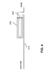
- Another preferred variant is in FIG. 4 shown.
- the capacitance C 240 couples the field emerging at the distal end of the coaxial outer conductor 220 backwards in a short electrical path to the proximal input into the coaxial section 220 and thus suppresses the envelope wave. Due to the skin effect, the high-frequency signals are conducted on the surface or the fields even propagate through the surrounding insulation (displacement currents). One speaks therefore of sheath waves. By contrast, the low-frequency therapy currents flow inside the conductor. With the barrier according to the invention, only the mantle shafts are to be blocked, which thus transport the unwanted HF energy.
- FIG. 4 shows a preferred installation of a standing wave trap in an electrode line.
- the sheath wave barrier realized from 220 and 240 (in between the dielectric - not shown here) is preferably mounted near the distal end of the electrode lead, preferably in the distal-side half of the electrode lead
- Characteristic of the invention is that the one conductor of the double line is realized by the therapeutic conductor (the function conductor) of the electrode lead itself, dielectric and second conductor (additional conductor) are guided only next door or around it, i. without the therapeutic conductor must be mechanically interrupted.
- the capacitor connects the ends of the additional conductor.
- the contacting here is only relevant for the MR properties of the electrode but not for its life-long therapeutic reliability.
- the interconnection of the thus constructed double line with the capacitor 240 in the manner described realizes a sheath wave barrier. According to the invention, this is realized so that it is resonant at at least one frequency. At this resonance frequency or at the plurality of resonance frequencies, the effect is maximum. According to the invention, these resonance frequencies are set so that they are close to the operating frequency of common MRI devices (see Table 1) in such a way that the bandwidths of these resonances max. 10 MHz.
- ferrites are used as sheath wave barriers for the frequency range of conventional MRI devices.
- FIG. 5 the equivalent circuit of the ferrite-free standing wave barrier according to the invention is shown, which in the embodiment in FIG. 3 is designed as a coaxial line section.
- the inner conductor is represented by the inductance 330 and the outer conductor by the inductance 340, the dielectric via the coupling capacitors 310, 320.
- the additional capacitance 350 causes a phase shift and thus destructively couples the sheath wave back. It is important to mention that, although the coaxial inner conductor shown in the equivalent circuit diagram as an inductance 330, but not structurally interrupted by an additional component or the coupling capacitors shown 320 are connected to this therapy-leading function guide.
- FIG. 6 shows a more detailed equivalent circuit in the form of a splice model, which represents the double line discretized as an LC network. It is also considered that the elements are really lossy (not shown, but considered in the Spice model).
- the capacitance indicated by 240 or 350 in the previous figures is called C21 here.
- the resistor and the voltage source belong to the measuring circuit which explains the operation. The current flowing through the measuring resistor R2 would flow into the tissue in the case of a real electrode and heat it accordingly during MR imaging.
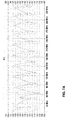
- FIG. 7A shows the result of a simulation based on the splice model FIG. 6 for a multi-resonant standing wave trap according to the invention, which is optimized to ensure that the same electrode is effectively protected in all 3 MRT devices listed in Table 1.
- the effect is particularly pronounced at the frequencies where the current is strongly attenuated. Shown are amplitudes and phase position of the current in the measuring resistor.
- FIG. 7B shows the result of a similar simulation in which the modeled standing wave trap uses an inductance instead of the capacitor 240 or C21.
- Table 1 Frequency (MHz) / MR magnetic field strength (T) Attenuation (dB) of the current relative to a signal at 1 kHz Reduction of warming by (%) 63.5 MHz / 1.5T 34.5 dB 99.9% 126.9 MHz / 3T 20.3 dB 99.0% 296.1 MHz / 7T 17 dB 98.0%
- Table 1 shows operating frequencies at a gyromagnetic ratio of 42.3 MHz / T for protons.
- the effect of FIG. 7A underlying embodiment variant is given with respect to a therapeutic / diagnostic useful signal at 1 kHz, since up to this frequency for therapeutic and diagnostic reasons, the electrode must function as undamped as possible
- the resonances of the standing wave barrier according to the invention are physically conditioned in certain frequency spacing ratios. Therefore, the desired operating frequencies of MR devices can not all be met equally well. However, the optimization of the components shown in Fig. 4 (in particular also with regard to the losses intended here for broadening the resonance low) makes possible a good compromise.
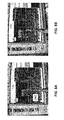
- FIG. 8 A realization form constructed as a helix is FIG. 8 shown.
- the illustrated implementation is only an example, so here the resonance is not at a typical MR frequency but can easily be tuned to it via a corresponding capacitor.
- FIG. 8 illustrated embodiment shows a coiled realization of the standing wave barrier in coaxial technology. on the screen behind it, the impedance is plotted and a clear peak can be seen when the capacitor 240 joins the coaxial outer conductor at its ends ( FIG. 8a ). This is not the case if the capacitor is missing ( FIG. 8b ).
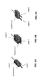
- FIGS. 9A to 9C show various embodiments of a double line.
- the double lead portion is formed as a coaxial conductor.
- the double lead portion formed as a parallel line of two flat conductors.
- the double lead portion is formed as a parallel line of two strip conductors.
Landscapes
- Health & Medical Sciences (AREA)
- Life Sciences & Earth Sciences (AREA)
- Heart & Thoracic Surgery (AREA)
- Engineering & Computer Science (AREA)
- Public Health (AREA)
- Nuclear Medicine, Radiotherapy & Molecular Imaging (AREA)
- Biomedical Technology (AREA)
- Animal Behavior & Ethology (AREA)
- General Health & Medical Sciences (AREA)
- Veterinary Medicine (AREA)
- Radiology & Medical Imaging (AREA)
- Cardiology (AREA)
- Surgery (AREA)
- Physics & Mathematics (AREA)
- Plasma & Fusion (AREA)
- Otolaryngology (AREA)
- Neurology (AREA)
- Medical Informatics (AREA)
- Molecular Biology (AREA)
- Vascular Medicine (AREA)
- Electrotherapy Devices (AREA)
Applications Claiming Priority (1)
| Application Number | Priority Date | Filing Date | Title |
|---|---|---|---|
| US201061424073P | 2010-12-17 | 2010-12-17 |
Publications (3)
| Publication Number | Publication Date |
|---|---|
| EP2465572A2 true EP2465572A2 (fr) | 2012-06-20 |
| EP2465572A3 EP2465572A3 (fr) | 2013-01-16 |
| EP2465572B1 EP2465572B1 (fr) | 2016-11-09 |
Family
ID=45217370
Family Applications (1)
| Application Number | Title | Priority Date | Filing Date |
|---|---|---|---|
| EP11191738.1A Not-in-force EP2465572B1 (fr) | 2010-12-17 | 2011-12-02 | Fil implantable compatible avec l'IRM |
Country Status (2)
| Country | Link |
|---|---|
| US (1) | US8942825B2 (fr) |
| EP (1) | EP2465572B1 (fr) |
Families Citing this family (7)
| Publication number | Priority date | Publication date | Assignee | Title |
|---|---|---|---|---|
| US9616218B2 (en) | 2011-11-04 | 2017-04-11 | Shanghai Microport Medical (Group) Co., Ltd. | Implantable passive medical lead |
| WO2013063796A1 (fr) | 2011-11-04 | 2013-05-10 | Shanghai Microport Medical (Group) Co., Ltd. | Dérivation médicale active implantable |
| US9199072B2 (en) | 2011-11-04 | 2015-12-01 | Shanghai Microport Medical (Group) Co., Ltd. | Implantable medical lead |
| WO2014000234A1 (fr) * | 2012-06-28 | 2014-01-03 | Shanghai Microport Medical (Group) Co., Ltd. | Ensemble de dérivation électrique cardiaque passive |
| CN103635227B (zh) | 2012-06-28 | 2016-05-25 | 上海微创医疗器械(集团)有限公司 | 主动心脏电导线 |
| EP2866883B1 (fr) * | 2012-06-28 | 2016-09-14 | Shanghai MicroPort Medical (Group) Co., Ltd. | Ensemble de dérivation électrique cardiaque active |
| US8664153B1 (en) | 2013-03-15 | 2014-03-04 | Sociedad Oxidquimica Limitada | Activated carbon as an adsorbent composition |
Family Cites Families (7)
| Publication number | Priority date | Publication date | Assignee | Title |
|---|---|---|---|---|
| US8244370B2 (en) | 2001-04-13 | 2012-08-14 | Greatbatch Ltd. | Band stop filter employing a capacitor and an inductor tank circuit to enhance MRI compatibility of active medical devices |
| US8219208B2 (en) | 2001-04-13 | 2012-07-10 | Greatbatch Ltd. | Frequency selective passive component networks for active implantable medical devices utilizing an energy dissipating surface |
| EP1878091B1 (fr) | 2005-05-04 | 2017-02-22 | Boston Scientific Neuromodulation Corporation | Fil electrique ameliore pour un dispositif electronique tel qu'un dispositif implantable |
| US7610101B2 (en) | 2006-11-30 | 2009-10-27 | Cardiac Pacemakers, Inc. | RF rejecting lead |
| JP5568316B2 (ja) * | 2007-03-19 | 2014-08-06 | ボストン サイエンティフィック ニューロモデュレイション コーポレイション | Mri/rf適合リード線、および関連のリード線を操作、作製する方法 |
| US8275464B2 (en) | 2007-12-06 | 2012-09-25 | Cardiac Pacemakers, Inc. | Leads with high surface resistance |
| US8818509B2 (en) | 2010-02-11 | 2014-08-26 | Biotronik Se & Co. Kg | Implantable element and electronic implant |
-
2011
- 2011-11-21 US US13/301,651 patent/US8942825B2/en active Active
- 2011-12-02 EP EP11191738.1A patent/EP2465572B1/fr not_active Not-in-force
Non-Patent Citations (1)
| Title |
|---|
| None |
Also Published As
| Publication number | Publication date |
|---|---|
| EP2465572A3 (fr) | 2013-01-16 |
| EP2465572B1 (fr) | 2016-11-09 |
| US8942825B2 (en) | 2015-01-27 |
| US20120157810A1 (en) | 2012-06-21 |
Similar Documents
| Publication | Publication Date | Title |
|---|---|---|
| EP2465572B1 (fr) | Fil implantable compatible avec l'IRM | |
| EP2359896B1 (fr) | Dispositif d'électrodes pour la commande de courant ou de tension entre un appareil électromédical implantable et un lieu de thérapie et/ou diagnostic dans le corps humain | |
| EP1923094B1 (fr) | Cathéter à électrode destiné à des interventions | |
| US8483840B2 (en) | Dual function tuned L-C input trap passive EMI filter component network for an active implantable medical device | |
| EP1923095B1 (fr) | Electrode destinée à des interventions | |
| DE102020100121A1 (de) | Implantierbare Elektrode mit einer Stichleitung | |
| EP2359895B1 (fr) | Sonde d'adaptation pour l'introduction d'implants médicaux actifs dans des dispositifs d'électrodes implantées et ensemble comprenant un dispositif d'électrodes implantables et une sonde d'adaptation | |
| EP2578268B1 (fr) | Capteur de température pour un appareil médical implantable | |
| EP2985053A1 (fr) | Ligne électrique implantable | |
| EP2465569B1 (fr) | Appareil implantable | |
| EP2446922B1 (fr) | Conducteurs implantables avec des conducteurs supplémentaires pour le découplage de champs | |
| EP2468353B1 (fr) | Appareil implantable | |
| EP2465573B1 (fr) | Appareil implantable | |
| EP2478933A2 (fr) | Appareil implantable | |
| EP2848282B1 (fr) | Appareil implantable | |
| EP2985054B1 (fr) | Appareil implantable doté d'un filtre électrique | |
| EP2465570B1 (fr) | Appareil implantable | |
| EP2468354A2 (fr) | Appareil implantable | |
| EP3025756B1 (fr) | Prolongement d'electrodes integre dans un implant actif | |
| EP2468356B1 (fr) | Appareil implantable | |
| EP2505229A2 (fr) | Appareil implantable | |
| EP2465571B1 (fr) | Appareil implantable | |
| DE102019107600B4 (de) | Antennenanordnung | |
| EP2457613A1 (fr) | Conduite implantable dotée d'un corps de conduite allongé longitudinalement | |
| DE102019106675A1 (de) | Leitung für ein medizinisches Implantat, mit integrierten periodischen Induktionsspulen (iPIC) für verringerte Wechselwirkungen mit elektromagnetischen Feldern |
Legal Events
| Date | Code | Title | Description |
|---|---|---|---|
| PUAI | Public reference made under article 153(3) epc to a published international application that has entered the european phase |
Free format text: ORIGINAL CODE: 0009012 |
|
| AK | Designated contracting states |
Kind code of ref document: A2 Designated state(s): AL AT BE BG CH CY CZ DE DK EE ES FI FR GB GR HR HU IE IS IT LI LT LU LV MC MK MT NL NO PL PT RO RS SE SI SK SM TR |
|
| AX | Request for extension of the european patent |
Extension state: BA ME |
|
| PUAL | Search report despatched |
Free format text: ORIGINAL CODE: 0009013 |
|
| AK | Designated contracting states |
Kind code of ref document: A3 Designated state(s): AL AT BE BG CH CY CZ DE DK EE ES FI FR GB GR HR HU IE IS IT LI LT LU LV MC MK MT NL NO PL PT RO RS SE SI SK SM TR |
|
| AX | Request for extension of the european patent |
Extension state: BA ME |
|
| RIC1 | Information provided on ipc code assigned before grant |
Ipc: A61N 1/08 20060101ALN20121212BHEP Ipc: A61N 1/05 20060101AFI20121212BHEP |
|
| 17P | Request for examination filed |
Effective date: 20130711 |
|
| RBV | Designated contracting states (corrected) |
Designated state(s): AL AT BE BG CH CY CZ DE DK EE ES FI FR GB GR HR HU IE IS IT LI LT LU LV MC MK MT NL NO PL PT RO RS SE SI SK SM TR |
|
| 17Q | First examination report despatched |
Effective date: 20150601 |
|
| GRAP | Despatch of communication of intention to grant a patent |
Free format text: ORIGINAL CODE: EPIDOSNIGR1 |
|
| RIC1 | Information provided on ipc code assigned before grant |
Ipc: A61N 1/05 20060101AFI20160425BHEP Ipc: A61N 1/08 20060101ALN20160425BHEP |
|
| INTG | Intention to grant announced |
Effective date: 20160512 |
|
| GRAJ | Information related to disapproval of communication of intention to grant by the applicant or resumption of examination proceedings by the epo deleted |
Free format text: ORIGINAL CODE: EPIDOSDIGR1 |
|
| REG | Reference to a national code |
Ref country code: DE Ref legal event code: R079 Ref document number: 502011011094 Country of ref document: DE Free format text: PREVIOUS MAIN CLASS: A61N0001080000 Ipc: A61N0001050000 |
|
| INTC | Intention to grant announced (deleted) | ||
| RIC1 | Information provided on ipc code assigned before grant |
Ipc: A61N 1/08 20060101ALN20160719BHEP Ipc: A61N 1/05 20060101AFI20160719BHEP |
|
| GRAR | Information related to intention to grant a patent recorded |
Free format text: ORIGINAL CODE: EPIDOSNIGR71 |
|
| GRAS | Grant fee paid |
Free format text: ORIGINAL CODE: EPIDOSNIGR3 |
|
| GRAA | (expected) grant |
Free format text: ORIGINAL CODE: 0009210 |
|
| INTG | Intention to grant announced |
Effective date: 20160929 |
|
| AK | Designated contracting states |
Kind code of ref document: B1 Designated state(s): AL AT BE BG CH CY CZ DE DK EE ES FI FR GB GR HR HU IE IS IT LI LT LU LV MC MK MT NL NO PL PT RO RS SE SI SK SM TR |
|
| REG | Reference to a national code |
Ref country code: GB Ref legal event code: FG4D Free format text: NOT ENGLISH |
|
| REG | Reference to a national code |
Ref country code: AT Ref legal event code: REF Ref document number: 843322 Country of ref document: AT Kind code of ref document: T Effective date: 20161115 Ref country code: CH Ref legal event code: EP |
|
| REG | Reference to a national code |
Ref country code: IE Ref legal event code: FG4D Free format text: LANGUAGE OF EP DOCUMENT: GERMAN |
|
| REG | Reference to a national code |
Ref country code: DE Ref legal event code: R096 Ref document number: 502011011094 Country of ref document: DE |
|
| PG25 | Lapsed in a contracting state [announced via postgrant information from national office to epo] |
Ref country code: LV Free format text: LAPSE BECAUSE OF FAILURE TO SUBMIT A TRANSLATION OF THE DESCRIPTION OR TO PAY THE FEE WITHIN THE PRESCRIBED TIME-LIMIT Effective date: 20161109 |
|
| REG | Reference to a national code |
Ref country code: LT Ref legal event code: MG4D |
|
| REG | Reference to a national code |
Ref country code: NL Ref legal event code: MP Effective date: 20161109 |
|
| PG25 | Lapsed in a contracting state [announced via postgrant information from national office to epo] |
Ref country code: LT Free format text: LAPSE BECAUSE OF FAILURE TO SUBMIT A TRANSLATION OF THE DESCRIPTION OR TO PAY THE FEE WITHIN THE PRESCRIBED TIME-LIMIT Effective date: 20161109 Ref country code: GR Free format text: LAPSE BECAUSE OF FAILURE TO SUBMIT A TRANSLATION OF THE DESCRIPTION OR TO PAY THE FEE WITHIN THE PRESCRIBED TIME-LIMIT Effective date: 20170210 Ref country code: SE Free format text: LAPSE BECAUSE OF FAILURE TO SUBMIT A TRANSLATION OF THE DESCRIPTION OR TO PAY THE FEE WITHIN THE PRESCRIBED TIME-LIMIT Effective date: 20161109 Ref country code: NO Free format text: LAPSE BECAUSE OF FAILURE TO SUBMIT A TRANSLATION OF THE DESCRIPTION OR TO PAY THE FEE WITHIN THE PRESCRIBED TIME-LIMIT Effective date: 20170209 Ref country code: NL Free format text: LAPSE BECAUSE OF FAILURE TO SUBMIT A TRANSLATION OF THE DESCRIPTION OR TO PAY THE FEE WITHIN THE PRESCRIBED TIME-LIMIT Effective date: 20161109 |
|
| PG25 | Lapsed in a contracting state [announced via postgrant information from national office to epo] |
Ref country code: IS Free format text: LAPSE BECAUSE OF FAILURE TO SUBMIT A TRANSLATION OF THE DESCRIPTION OR TO PAY THE FEE WITHIN THE PRESCRIBED TIME-LIMIT Effective date: 20170309 Ref country code: RS Free format text: LAPSE BECAUSE OF FAILURE TO SUBMIT A TRANSLATION OF THE DESCRIPTION OR TO PAY THE FEE WITHIN THE PRESCRIBED TIME-LIMIT Effective date: 20161109 Ref country code: BE Free format text: LAPSE BECAUSE OF NON-PAYMENT OF DUE FEES Effective date: 20161231 Ref country code: FI Free format text: LAPSE BECAUSE OF FAILURE TO SUBMIT A TRANSLATION OF THE DESCRIPTION OR TO PAY THE FEE WITHIN THE PRESCRIBED TIME-LIMIT Effective date: 20161109 Ref country code: HR Free format text: LAPSE BECAUSE OF FAILURE TO SUBMIT A TRANSLATION OF THE DESCRIPTION OR TO PAY THE FEE WITHIN THE PRESCRIBED TIME-LIMIT Effective date: 20161109 Ref country code: PL Free format text: LAPSE BECAUSE OF FAILURE TO SUBMIT A TRANSLATION OF THE DESCRIPTION OR TO PAY THE FEE WITHIN THE PRESCRIBED TIME-LIMIT Effective date: 20161109 Ref country code: ES Free format text: LAPSE BECAUSE OF FAILURE TO SUBMIT A TRANSLATION OF THE DESCRIPTION OR TO PAY THE FEE WITHIN THE PRESCRIBED TIME-LIMIT Effective date: 20161109 Ref country code: PT Free format text: LAPSE BECAUSE OF FAILURE TO SUBMIT A TRANSLATION OF THE DESCRIPTION OR TO PAY THE FEE WITHIN THE PRESCRIBED TIME-LIMIT Effective date: 20170309 |
|
| PG25 | Lapsed in a contracting state [announced via postgrant information from national office to epo] |
Ref country code: RO Free format text: LAPSE BECAUSE OF FAILURE TO SUBMIT A TRANSLATION OF THE DESCRIPTION OR TO PAY THE FEE WITHIN THE PRESCRIBED TIME-LIMIT Effective date: 20161109 Ref country code: DK Free format text: LAPSE BECAUSE OF FAILURE TO SUBMIT A TRANSLATION OF THE DESCRIPTION OR TO PAY THE FEE WITHIN THE PRESCRIBED TIME-LIMIT Effective date: 20161109 Ref country code: EE Free format text: LAPSE BECAUSE OF FAILURE TO SUBMIT A TRANSLATION OF THE DESCRIPTION OR TO PAY THE FEE WITHIN THE PRESCRIBED TIME-LIMIT Effective date: 20161109 Ref country code: CZ Free format text: LAPSE BECAUSE OF FAILURE TO SUBMIT A TRANSLATION OF THE DESCRIPTION OR TO PAY THE FEE WITHIN THE PRESCRIBED TIME-LIMIT Effective date: 20161109 Ref country code: SK Free format text: LAPSE BECAUSE OF FAILURE TO SUBMIT A TRANSLATION OF THE DESCRIPTION OR TO PAY THE FEE WITHIN THE PRESCRIBED TIME-LIMIT Effective date: 20161109 |
|
| REG | Reference to a national code |
Ref country code: DE Ref legal event code: R097 Ref document number: 502011011094 Country of ref document: DE |
|
| PG25 | Lapsed in a contracting state [announced via postgrant information from national office to epo] |
Ref country code: SM Free format text: LAPSE BECAUSE OF FAILURE TO SUBMIT A TRANSLATION OF THE DESCRIPTION OR TO PAY THE FEE WITHIN THE PRESCRIBED TIME-LIMIT Effective date: 20161109 Ref country code: IT Free format text: LAPSE BECAUSE OF FAILURE TO SUBMIT A TRANSLATION OF THE DESCRIPTION OR TO PAY THE FEE WITHIN THE PRESCRIBED TIME-LIMIT Effective date: 20161109 Ref country code: BG Free format text: LAPSE BECAUSE OF FAILURE TO SUBMIT A TRANSLATION OF THE DESCRIPTION OR TO PAY THE FEE WITHIN THE PRESCRIBED TIME-LIMIT Effective date: 20170209 |
|
| PLBE | No opposition filed within time limit |
Free format text: ORIGINAL CODE: 0009261 |
|
| STAA | Information on the status of an ep patent application or granted ep patent |
Free format text: STATUS: NO OPPOSITION FILED WITHIN TIME LIMIT |
|
| PG25 | Lapsed in a contracting state [announced via postgrant information from national office to epo] |
Ref country code: MC Free format text: LAPSE BECAUSE OF FAILURE TO SUBMIT A TRANSLATION OF THE DESCRIPTION OR TO PAY THE FEE WITHIN THE PRESCRIBED TIME-LIMIT Effective date: 20161109 |
|
| REG | Reference to a national code |
Ref country code: FR Ref legal event code: ST Effective date: 20170831 |
|
| 26N | No opposition filed |
Effective date: 20170810 |
|
| GBPC | Gb: european patent ceased through non-payment of renewal fee |
Effective date: 20170209 |
|
| PG25 | Lapsed in a contracting state [announced via postgrant information from national office to epo] |
Ref country code: FR Free format text: LAPSE BECAUSE OF NON-PAYMENT OF DUE FEES Effective date: 20170109 Ref country code: LU Free format text: LAPSE BECAUSE OF NON-PAYMENT OF DUE FEES Effective date: 20161202 |
|
| PG25 | Lapsed in a contracting state [announced via postgrant information from national office to epo] |
Ref country code: SI Free format text: LAPSE BECAUSE OF FAILURE TO SUBMIT A TRANSLATION OF THE DESCRIPTION OR TO PAY THE FEE WITHIN THE PRESCRIBED TIME-LIMIT Effective date: 20161109 |
|
| REG | Reference to a national code |
Ref country code: BE Ref legal event code: MM Effective date: 20161231 |
|
| REG | Reference to a national code |
Ref country code: AT Ref legal event code: MM01 Ref document number: 843322 Country of ref document: AT Kind code of ref document: T Effective date: 20161202 |
|
| PG25 | Lapsed in a contracting state [announced via postgrant information from national office to epo] |
Ref country code: GB Free format text: LAPSE BECAUSE OF NON-PAYMENT OF DUE FEES Effective date: 20170209 |
|
| PG25 | Lapsed in a contracting state [announced via postgrant information from national office to epo] |
Ref country code: AT Free format text: LAPSE BECAUSE OF NON-PAYMENT OF DUE FEES Effective date: 20161202 Ref country code: HU Free format text: LAPSE BECAUSE OF FAILURE TO SUBMIT A TRANSLATION OF THE DESCRIPTION OR TO PAY THE FEE WITHIN THE PRESCRIBED TIME-LIMIT; INVALID AB INITIO Effective date: 20111202 Ref country code: CY Free format text: LAPSE BECAUSE OF FAILURE TO SUBMIT A TRANSLATION OF THE DESCRIPTION OR TO PAY THE FEE WITHIN THE PRESCRIBED TIME-LIMIT Effective date: 20161109 |
|
| PG25 | Lapsed in a contracting state [announced via postgrant information from national office to epo] |
Ref country code: TR Free format text: LAPSE BECAUSE OF FAILURE TO SUBMIT A TRANSLATION OF THE DESCRIPTION OR TO PAY THE FEE WITHIN THE PRESCRIBED TIME-LIMIT Effective date: 20161109 Ref country code: MK Free format text: LAPSE BECAUSE OF FAILURE TO SUBMIT A TRANSLATION OF THE DESCRIPTION OR TO PAY THE FEE WITHIN THE PRESCRIBED TIME-LIMIT Effective date: 20161109 |
|
| PG25 | Lapsed in a contracting state [announced via postgrant information from national office to epo] |
Ref country code: MT Free format text: LAPSE BECAUSE OF FAILURE TO SUBMIT A TRANSLATION OF THE DESCRIPTION OR TO PAY THE FEE WITHIN THE PRESCRIBED TIME-LIMIT Effective date: 20161109 |
|
| PG25 | Lapsed in a contracting state [announced via postgrant information from national office to epo] |
Ref country code: AL Free format text: LAPSE BECAUSE OF FAILURE TO SUBMIT A TRANSLATION OF THE DESCRIPTION OR TO PAY THE FEE WITHIN THE PRESCRIBED TIME-LIMIT Effective date: 20161109 |
|
| PGFP | Annual fee paid to national office [announced via postgrant information from national office to epo] |
Ref country code: IE Payment date: 20211220 Year of fee payment: 11 |
|
| PGFP | Annual fee paid to national office [announced via postgrant information from national office to epo] |
Ref country code: CH Payment date: 20211222 Year of fee payment: 11 |
|
| PGFP | Annual fee paid to national office [announced via postgrant information from national office to epo] |
Ref country code: DE Payment date: 20211222 Year of fee payment: 11 |
|
| REG | Reference to a national code |
Ref country code: DE Ref legal event code: R119 Ref document number: 502011011094 Country of ref document: DE |
|
| REG | Reference to a national code |
Ref country code: CH Ref legal event code: PL |
|
| PG25 | Lapsed in a contracting state [announced via postgrant information from national office to epo] |
Ref country code: LI Free format text: LAPSE BECAUSE OF NON-PAYMENT OF DUE FEES Effective date: 20221231 Ref country code: IE Free format text: LAPSE BECAUSE OF NON-PAYMENT OF DUE FEES Effective date: 20221202 Ref country code: DE Free format text: LAPSE BECAUSE OF NON-PAYMENT OF DUE FEES Effective date: 20230701 Ref country code: CH Free format text: LAPSE BECAUSE OF NON-PAYMENT OF DUE FEES Effective date: 20221231 |