EP2465742B1 - Pneumatischer Hilfsservomotor zum Bremsen eines Fahrzeugs mit Empfindungserhaltung am Bremspedal - Google Patents
Pneumatischer Hilfsservomotor zum Bremsen eines Fahrzeugs mit Empfindungserhaltung am Bremspedal Download PDFInfo
- Publication number
- EP2465742B1 EP2465742B1 EP11192946.9A EP11192946A EP2465742B1 EP 2465742 B1 EP2465742 B1 EP 2465742B1 EP 11192946 A EP11192946 A EP 11192946A EP 2465742 B1 EP2465742 B1 EP 2465742B1
- Authority
- EP
- European Patent Office
- Prior art keywords
- channel
- skirt
- master cylinder
- moving gear
- chamber
- Prior art date
- Legal status (The legal status is an assumption and is not a legal conclusion. Google has not performed a legal analysis and makes no representation as to the accuracy of the status listed.)
- Not-in-force
Links
- 239000012530 fluid Substances 0.000 claims description 7
- 230000001419 dependent effect Effects 0.000 claims description 2
- 238000006073 displacement reaction Methods 0.000 description 8
- 208000031968 Cadaver Diseases 0.000 description 4
- OKTJSMMVPCPJKN-UHFFFAOYSA-N Carbon Chemical compound [C] OKTJSMMVPCPJKN-UHFFFAOYSA-N 0.000 description 2
- 229910052799 carbon Inorganic materials 0.000 description 2
- 238000006243 chemical reaction Methods 0.000 description 2
- 238000005265 energy consumption Methods 0.000 description 2
- 238000005192 partition Methods 0.000 description 2
- 241001080024 Telles Species 0.000 description 1
- 238000004891 communication Methods 0.000 description 1
- 238000013016 damping Methods 0.000 description 1
- 230000001934 delay Effects 0.000 description 1
- 230000000994 depressogenic effect Effects 0.000 description 1
- 238000005259 measurement Methods 0.000 description 1
- 230000009466 transformation Effects 0.000 description 1
Images


Classifications
-
- B—PERFORMING OPERATIONS; TRANSPORTING
- B60—VEHICLES IN GENERAL
- B60T—VEHICLE BRAKE CONTROL SYSTEMS OR PARTS THEREOF; BRAKE CONTROL SYSTEMS OR PARTS THEREOF, IN GENERAL; ARRANGEMENT OF BRAKING ELEMENTS ON VEHICLES IN GENERAL; PORTABLE DEVICES FOR PREVENTING UNWANTED MOVEMENT OF VEHICLES; VEHICLE MODIFICATIONS TO FACILITATE COOLING OF BRAKES
- B60T11/00—Transmitting braking action from initiating means to ultimate brake actuator without power assistance or drive or where such assistance or drive is irrelevant
- B60T11/10—Transmitting braking action from initiating means to ultimate brake actuator without power assistance or drive or where such assistance or drive is irrelevant transmitting by fluid means, e.g. hydraulic
- B60T11/16—Master control, e.g. master cylinders
- B60T11/232—Recuperation valves
-
- B—PERFORMING OPERATIONS; TRANSPORTING
- B60—VEHICLES IN GENERAL
- B60T—VEHICLE BRAKE CONTROL SYSTEMS OR PARTS THEREOF; BRAKE CONTROL SYSTEMS OR PARTS THEREOF, IN GENERAL; ARRANGEMENT OF BRAKING ELEMENTS ON VEHICLES IN GENERAL; PORTABLE DEVICES FOR PREVENTING UNWANTED MOVEMENT OF VEHICLES; VEHICLE MODIFICATIONS TO FACILITATE COOLING OF BRAKES
- B60T13/00—Transmitting braking action from initiating means to ultimate brake actuator with power assistance or drive; Brake systems incorporating such transmitting means, e.g. air-pressure brake systems
- B60T13/10—Transmitting braking action from initiating means to ultimate brake actuator with power assistance or drive; Brake systems incorporating such transmitting means, e.g. air-pressure brake systems with fluid assistance, drive, or release
- B60T13/24—Transmitting braking action from initiating means to ultimate brake actuator with power assistance or drive; Brake systems incorporating such transmitting means, e.g. air-pressure brake systems with fluid assistance, drive, or release the fluid being gaseous
- B60T13/46—Vacuum systems
- B60T13/52—Vacuum systems indirect, i.e. vacuum booster units
-
- B—PERFORMING OPERATIONS; TRANSPORTING
- B60—VEHICLES IN GENERAL
- B60T—VEHICLE BRAKE CONTROL SYSTEMS OR PARTS THEREOF; BRAKE CONTROL SYSTEMS OR PARTS THEREOF, IN GENERAL; ARRANGEMENT OF BRAKING ELEMENTS ON VEHICLES IN GENERAL; PORTABLE DEVICES FOR PREVENTING UNWANTED MOVEMENT OF VEHICLES; VEHICLE MODIFICATIONS TO FACILITATE COOLING OF BRAKES
- B60T13/00—Transmitting braking action from initiating means to ultimate brake actuator with power assistance or drive; Brake systems incorporating such transmitting means, e.g. air-pressure brake systems
- B60T13/10—Transmitting braking action from initiating means to ultimate brake actuator with power assistance or drive; Brake systems incorporating such transmitting means, e.g. air-pressure brake systems with fluid assistance, drive, or release
- B60T13/24—Transmitting braking action from initiating means to ultimate brake actuator with power assistance or drive; Brake systems incorporating such transmitting means, e.g. air-pressure brake systems with fluid assistance, drive, or release the fluid being gaseous
- B60T13/46—Vacuum systems
- B60T13/52—Vacuum systems indirect, i.e. vacuum booster units
- B60T13/565—Vacuum systems indirect, i.e. vacuum booster units characterised by being associated with master cylinders, e.g. integrally formed
Definitions
- the invention relates to a pneumatic brake booster of a vehicle, particularly a motor vehicle.
- the invention aims to reduce the energy consumption of such a vehicle while maintaining a reduced stroke to the brake pedal and a high force produced by said servomotor.
- a pneumatic brake booster comprises a front chamber connectable to a vacuum source, a rear chamber connectable to a high pressure inlet, typically the atmospheric pressure, and a sealed moving partition disposed between the two chambers.
- the servomotor also comprises a push rod mechanically connected to a brake pedal disposed at the input of the servomotor.
- a hydraulic braking circuit is connected to the output of the servomotor. Servomotors are described in US 2005/099062 , US 5,056,313 and FR 2,770,475 .
- the servomotor comprises a movable element which can be carried by means of the thrust rod and by the movable partition towards the hydraulic braking circuit.
- the hydraulic braking circuit comprises a master cylinder, at least one hydraulic conduit and at least one braking device of the vehicle.
- the master cylinder comprises a primary hydraulic chamber and a primary piston sliding in said primary hydraulic chamber.
- the duct internally connects the primary hydraulic chamber to the braking device.
- the braking device may be of the disc brake or drum brake type and is intended for braking a wheel of the vehicle.
- the braking device comprises a brake lining and a friction surface.
- the brake lining may be fixedly mounted relative to the wheel while the friction surface is mounted rotatably connected to the wheel. Following a hydraulic pressure generated by the master cylinder, the brake lining is applied against the friction surface in order to cause the rotation to slow down, see the stop in rotation of the wheel of the vehicle to which this device is connected. braking.
- the hydraulic fluid filling the primary chamber, filled also the conduit of the hydraulic braking circuit to the braking device.
- the braking device To reduce the carbon emissions produced by the vehicles, it is intended to act on the braking device. In particular, it is intended to move the brake lining away from its friction surface until no more frictional torque is formed between the brake lining and the friction surface in the rest position.
- position of rest By position of rest is meant position of the brake lining with respect to its friction surface, when the vehicle is not in the braking phase.
- the invention therefore allows the brake linings to be moved away from their friction surface by a distance, the result of which is that the vehicle will not consume in excess of energy because of the position of the brake linings with respect to their surface. friction.
- an internal game-absorbing device which operates under pressure instead of operating in volume.
- the invention provides for producing an additional chamber formed by the servomotor and communicating with the hydraulic braking circuit via a channel.
- the canal internally connects the additional chamber to the primary chamber of the master cylinder.
- the additional chamber is filled with the same hydraulic fluid as that filling the primary chamber of the master cylinder.
- the volume of the additional chamber is reduced until a threshold hydraulic pressure is obtained which corresponds to the pressure required in the hydraulic braking circuit to fill all the games. .
- the skirt is moved independently of the moving equipment. At the moment when the threshold hydraulic pressure is reached, the skirt is connected to the moving equipment to form a single body which moves in one piece.
- a valve is provided mounted on the channel. This valve controls the closing of the channel when the threshold hydraulic pressure recorded in the primary chamber has been reached. More specifically, it is the hydraulic pressure exerted on said valve which will control its movement to allow the closure of the channel.
- the invention allows pressure adjustment rather than volume adjustment.
- the invention advantageously allows a smaller amount of air to enter the servomotor.
- the invention also advantageously makes it possible not to press a too long distance on the brake pedal to obtain the desired pressure.
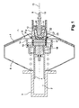
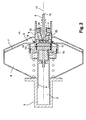
- the figure 1 illustrates a pneumatic brake booster 1 of a vehicle, according to the invention.
- the pneumatic servomotor 1 is able to be connected to a primary chamber 2 of a master cylinder 3 of said vehicle.
- the servomotor 1 makes it possible to amplify a braking force via a hydraulic braking circuit (not shown).
- a hydraulic braking circuit comprises the master cylinder 3, at least one hydraulic duct (not shown) and at least one braking device (not shown).
- the master cylinder 3 comprises the primary chamber 2 and a primary piston 4, and advantageously a secondary chamber and a secondary piston (not shown).
- the servomotor 1 is connected to the primary piston 4 which it drives in displacement after being urged by a brake pedal (not shown).
- the hydraulic conduit connects the interior of the primary chamber 2 to the braking device.
- the braking device is formed by a brake lining (not shown) and a friction surface (not shown).
- the friction surface may be rotatably connected to a wheel of the vehicle while the brake lining is fixedly mounted to another fixed support.
- the brake lining can then be displaced by the hydraulic pressure generated by the master cylinder and the servomotor in order to approach its friction surface when braking is controlled.
- the brake lining is then brought into contact with the friction surface which causes a slowing down, or even stopping, of the rotation of the wheel concerned.
- the servomotor 1 comprises a push rod 5, a moving element 6, a sealed skirt 7, a front chamber 8 connectable to a vacuum source and a rear chamber 9 connectable to a high pressure source, typically air at atmospheric pressure.
- the push rod 5 is connected to the brake pedal at one end 10 and to the moving element 6 at an opposite end 11.
- the moving element 6 slides in a sealed manner through the skirt 7 while being connected to the primary piston 4 of the master cylinder 3.
- the sealed skirt 7 is moved towards the master cylinder 3 after pressing the brake pedal.
- the front chamber 8 and the rear chamber 9 are separated by the skirt 7 in a sealed manner.
- the push rod 5 is placed in abutment against a stop 12 isolating the rear chamber 9 of the high pressure source.
- the stop 12 is formed by the mobile assembly 6.
- the front chamber 8 and the rear chamber 9 communicate and are under vacuum.
- the communication between the front chamber 8 and the rear chamber 9 is broken.
- the push rod 5 is driven in displacement towards the master cylinder 3 then causing a gap of the push rod 5 relative to the stop 12.
- Air can then be inserted through the space thus released between the thrust rod 5 and the abutment 12.
- the air is then introduced into the rear chamber 9. Due to the pressure difference existing between the rear chamber 9 and the front chamber 8, the introduced air exerts a pressure on the the skirt 7 causing the displacement of the skirt 7 longitudinally relative to an axis 13 of displacement of the push rod 5 towards the master cylinder 3. This pressure takes over the force exerted by the driver's foot.
- the servomotor 1 also comprises a hydraulic fluid reservoir 14 communicating with the interior of the primary chamber 2 of the master cylinder 3 via a channel 15.
- the reservoir 14 is formed by the skirt 7 and by the moving assembly 6.
- the skirt 7 and the moving assembly 6 slide relative to one another while delimiting a space 16 whose volume varies according to the position of the rigid skirt 7 relative to that of the moving element 6.
- the channel 15 is formed through the moving element 6 and opens into the primary chamber 2 through the primary piston 4.
- a valve 16 is also provided. This valve 16 is mounted on the moving element 6 and more precisely on the channel 15.
- this valve 16 is sensitive to the hydraulic pressure prevailing in the primary chamber 2. As soon as a threshold value of hydraulic pressure is recorded in the primary chamber 2, the valve 16 causes the closure of the channel 15.
- the valve 16 is formed by a sliding piece 17 and by elastic means 18.
- the piece 17 slides in a sealed manner along a cylindrical body formed by the moving assembly 6.
- the sliding part 17 is mounted in abutment against the cylindrical body of the moving element 6 in the direction of the master cylinder 3. In this position, the channel 15 is open and the reservoir 14 freely communicates with the primary chamber 2.
- the sliding part 17 has a duct 19 which is made in such a way as to be positioned opposite the channel 15 to allow the passage of the fluid from the reservoir 14 to the primary chamber 2.
- a spring 18 is provided which bears the sliding part 17 against the cylindrical body as long as the hydraulic threshold pressure prevailing in the primary chamber 2 and acting on the sliding part 17 has not been reached. reached.
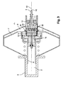
- a reaction disc 21 comprising a damping mattress 22 and a cup 23 receiving said mattress 22.
- the push rod 5 and the movable assembly 6 are intended to rest against this mattress 22 to during the braking phase. To do this, the mobile assembly 6 forms an internal shoulder 24 coming to bear against the mattress 22.
- the push rod 5 rests against the mattress 22 by its end 11.
- FIG. 4 the moving equipment 6 is then also driven in displacement towards the master cylinder 3.
- the mattress 22 and the shoulder 24 of the moving equipment 6 eventually meet.
- the shoulder 24 bears against an outer periphery of the mattress 22.
Landscapes
- Engineering & Computer Science (AREA)
- Transportation (AREA)
- Mechanical Engineering (AREA)
- Braking Systems And Boosters (AREA)
Claims (4)
- Bremshilfe-Servomotor (1) eines Fahrzeugs, der mit einem Hauptzylinder (3) des Fahrzeugs verbunden werden kann, wobei der Servomotor aufweist- eine Schubstange (5),- ein bewegliches Teil (6),- eine dichte Schürze (7),- eine vordere Kammer (8) und eine hintere Kammer (9), die von der Schürze dicht getrennt werden, wobei die Schubstange über ein Ende (10) mit einem Bremspedal und über ein gegenüberliegendes Ende (11) mit dem beweglichen Teil verbunden ist, wobei das bewegliche Teil dicht durch die Schürze gleitet und dabei mit einem Primärkolben (4) des Hauptzylinders verbunden ist, wobei die dichte Schürze nach Drücken auf das Bremspedal in Richtung des Hauptzylinders verschoben wird, dadurch gekennzeichnet, dass er aufweist- einen Hydraulikfluidbehälter (14), der mit dem Inneren einer Primärkammer des Hauptzylinders über einen Kanal (15) in Verbindung steht, und- eine Schließeinrichtung (16, 17, 18) des Kanals, deren Betrieb vom in der Primärkammer herrschenden Hydraulikdruck abhängt, und dass der Behälter von der Schürze und vom beweglichen Teil geformt wird, wobei die Schürze und das bewegliche Teil zueinander gleiten und dabei einen Raum begrenzen, dessen Volumen abhängig von der Stellung der steifen Schürze bezüglich derjenigen des beweglichen Teils variiert.
- Servomotor nach Anspruch 1, dadurch gekennzeichnet, dass- das bewegliche Teil einen zylindrischen Körper aufweist, durch den hindurch der Kanal geformt ist, wobei der Kanal vom Behälter zur Primärkammer durch den Primärkolben mündet, und die Schließeinrichtung des Kanals von einem Ventil geformt wird, das auf den Körper montiert und über einem hydraulischen Schwellendruck verschiebbar ist, der auf das Ventil ausgeübt wird, um das Schließen des Kanals zu bewirken.
- Servomotor nach Anspruch 2, dadurch gekennzeichnet, dass das Ventil auf dem Kanal angeordnet ist und von einem gleitenden Bauteil (17) und von elastischen Einrichtungen (18) geformt wird, wobei die elastischen Einrichtungen so konfiguriert sind, dass sie das gleitende Bauteil in Auflage gegen den Körper halten, um die Öffnung des Kanals zu erlauben, und dass sie die Verschiebung des gleitenden Bauteils erlauben, um den Kanal über einem hydraulischen Schwellendruck zu schließen, der auf das gleitende Bauteil ausgeübt wird.
- Servomotor nach Anspruch 3, dadurch gekennzeichnet, dass die elastischen Einrichtungen von einer Feder geformt werden, die sich zwischen dem Körper und dem gleitenden Bauteil befindet.
Applications Claiming Priority (1)
| Application Number | Priority Date | Filing Date | Title |
|---|---|---|---|
| FR1004902A FR2969091B1 (fr) | 2010-12-15 | 2010-12-15 | Servomoteur pneumatique d'assistance de freinage d'un vehicule avec conservation du ressenti au niveau de la pedale de frein |
Publications (2)
| Publication Number | Publication Date |
|---|---|
| EP2465742A1 EP2465742A1 (de) | 2012-06-20 |
| EP2465742B1 true EP2465742B1 (de) | 2015-12-02 |
Family
ID=44533274
Family Applications (1)
| Application Number | Title | Priority Date | Filing Date |
|---|---|---|---|
| EP11192946.9A Not-in-force EP2465742B1 (de) | 2010-12-15 | 2011-12-12 | Pneumatischer Hilfsservomotor zum Bremsen eines Fahrzeugs mit Empfindungserhaltung am Bremspedal |
Country Status (2)
| Country | Link |
|---|---|
| EP (1) | EP2465742B1 (de) |
| FR (1) | FR2969091B1 (de) |
Families Citing this family (1)
| Publication number | Priority date | Publication date | Assignee | Title |
|---|---|---|---|---|
| EP2716515B1 (de) * | 2012-10-05 | 2016-03-23 | Robert Bosch Gmbh | Primärkolbenbaugruppe für einen Masterzylinder eines Hydraulikbremssystems und Verfahren zum Betreiben eines Hydraulikbremssystems |
Family Cites Families (3)
| Publication number | Priority date | Publication date | Assignee | Title |
|---|---|---|---|---|
| US5056313A (en) * | 1990-11-01 | 1991-10-15 | General Motors Corporation | Three piston master cylinder |
| FR2770475B1 (fr) * | 1997-10-30 | 1999-12-17 | Bosch Syst Freinage | Maitre-cylindre a clapets a course morte reduite |
| JP2005138736A (ja) * | 2003-11-07 | 2005-06-02 | Advics:Kk | 液圧ブレーキ装置 |
-
2010
- 2010-12-15 FR FR1004902A patent/FR2969091B1/fr not_active Expired - Fee Related
-
2011
- 2011-12-12 EP EP11192946.9A patent/EP2465742B1/de not_active Not-in-force
Also Published As
| Publication number | Publication date |
|---|---|
| EP2465742A1 (de) | 2012-06-20 |
| FR2969091B1 (fr) | 2013-03-22 |
| FR2969091A1 (fr) | 2012-06-22 |
Similar Documents
| Publication | Publication Date | Title |
|---|---|---|
| FR2967120A1 (fr) | Dispositif a piston et cylindre pour refouler un liquide hydraulique, notamment pour un frein de vehicule | |
| EP0912382B1 (de) | Bremskraftverstärker mit veränderbarer verstärkungsverhaltung | |
| EP0939713B1 (de) | Hilfskraftbremsvorrichtung mit variablem verstärkerverhältnis und verringerter hysterese | |
| FR2578799A1 (fr) | Systeme hydraulique de freinage. | |
| EP2465742A1 (de) | Pneumatischer Hilfsservomotor zum Bremsen eines Fahrzeugs mit Empfindungserhaltung am Bremspedal | |
| EP1457400A1 (de) | Bremskraftvorrichtung mit verbesserter Bremsempfindlichkeit | |
| WO1996007572A1 (fr) | Dispositif de freinage assiste a course masquee et a securite accrue | |
| EP0004513B1 (de) | Hydropneumatische Vorrichtung zur synchronisierten Betätigung der Kupplung und der Getriebeverriegelung | |
| EP0993399B1 (de) | Hauptzylinder mit dynamischer hydraulischer reaktion und mit schwimmendem kolben | |
| EP1097073B1 (de) | Verbesserter hauptzylinder mit hydraulischer reaktion und selektiver selbstverstärkung | |
| EP0802868B1 (de) | Bremskraftverstärker mit reduziertem pedalweg | |
| EP0991555B1 (de) | Hauptzylinder mit hydraulisch dynamischer reaktion geregelt durch einen querschnittsunterschied | |
| EP2646300B1 (de) | Hydraulikaggregat zur bremsung eines fahrzeugs und zur verminderung des leerweges des fahrzeugs | |
| EP1225112B1 (de) | Bremskraftverstärker mit zwei Verstärkungsverhältnissen für Kraftfahrzeuge | |
| EP1365949B1 (de) | Kraftfahrzeugbremsvorrichtung | |
| EP1077853B1 (de) | Hauptbremszylinder mit von der viskosität unabhängiger hydraulischer reaktion | |
| EP1564098B1 (de) | Bremssystem mit Geberzylinder und Unterdruckkraftverstärker | |
| FR2700513A1 (fr) | Dispositif de freinage assisté à réaction mixte et course masquée. | |
| FR2696141A1 (fr) | Dispositif de freinage assisté à réaction hydraulique et course masquée. | |
| FR2480690A1 (fr) | Servofrein hydraulique | |
| FR2967386A1 (fr) | Agencement de commande de freinage comportant un servomoteur equipe d'un regulateur de pression deporte et d'une valve de reequilibrage rapide | |
| FR2772709A1 (fr) | Systeme de freinage | |
| FR2736605A1 (fr) | Dispositif de freinage assiste a temps de reponse ameliore | |
| BE536667A (de) | ||
| FR2653726A1 (fr) | Servomoteur pneumatique d'assistance au freinage. |
Legal Events
| Date | Code | Title | Description |
|---|---|---|---|
| PUAI | Public reference made under article 153(3) epc to a published international application that has entered the european phase |
Free format text: ORIGINAL CODE: 0009012 |
|
| AK | Designated contracting states |
Kind code of ref document: A1 Designated state(s): AL AT BE BG CH CY CZ DE DK EE ES FI FR GB GR HR HU IE IS IT LI LT LU LV MC MK MT NL NO PL PT RO RS SE SI SK SM TR |
|
| AX | Request for extension of the european patent |
Extension state: BA ME |
|
| 17P | Request for examination filed |
Effective date: 20121220 |
|
| GRAP | Despatch of communication of intention to grant a patent |
Free format text: ORIGINAL CODE: EPIDOSNIGR1 |
|
| INTG | Intention to grant announced |
Effective date: 20150901 |
|
| GRAS | Grant fee paid |
Free format text: ORIGINAL CODE: EPIDOSNIGR3 |
|
| GRAA | (expected) grant |
Free format text: ORIGINAL CODE: 0009210 |
|
| AK | Designated contracting states |
Kind code of ref document: B1 Designated state(s): AL AT BE BG CH CY CZ DE DK EE ES FI FR GB GR HR HU IE IS IT LI LT LU LV MC MK MT NL NO PL PT RO RS SE SI SK SM TR |
|
| REG | Reference to a national code |
Ref country code: GB Ref legal event code: FG4D Free format text: NOT ENGLISH |
|
| REG | Reference to a national code |
Ref country code: AT Ref legal event code: REF Ref document number: 763466 Country of ref document: AT Kind code of ref document: T Effective date: 20151215 Ref country code: CH Ref legal event code: EP |
|
| REG | Reference to a national code |
Ref country code: IE Ref legal event code: FG4D Free format text: LANGUAGE OF EP DOCUMENT: FRENCH |
|
| REG | Reference to a national code |
Ref country code: DE Ref legal event code: R096 Ref document number: 602011021775 Country of ref document: DE |
|
| REG | Reference to a national code |
Ref country code: FR Ref legal event code: PLFP Year of fee payment: 5 |
|
| REG | Reference to a national code |
Ref country code: NL Ref legal event code: MP Effective date: 20160302 |
|
| REG | Reference to a national code |
Ref country code: LT Ref legal event code: MG4D |
|
| REG | Reference to a national code |
Ref country code: AT Ref legal event code: MK05 Ref document number: 763466 Country of ref document: AT Kind code of ref document: T Effective date: 20151202 |
|
| PG25 | Lapsed in a contracting state [announced via postgrant information from national office to epo] |
Ref country code: LT Free format text: LAPSE BECAUSE OF FAILURE TO SUBMIT A TRANSLATION OF THE DESCRIPTION OR TO PAY THE FEE WITHIN THE PRESCRIBED TIME-LIMIT Effective date: 20151202 Ref country code: ES Free format text: LAPSE BECAUSE OF FAILURE TO SUBMIT A TRANSLATION OF THE DESCRIPTION OR TO PAY THE FEE WITHIN THE PRESCRIBED TIME-LIMIT Effective date: 20151202 Ref country code: NO Free format text: LAPSE BECAUSE OF FAILURE TO SUBMIT A TRANSLATION OF THE DESCRIPTION OR TO PAY THE FEE WITHIN THE PRESCRIBED TIME-LIMIT Effective date: 20160302 |
|
| PG25 | Lapsed in a contracting state [announced via postgrant information from national office to epo] |
Ref country code: GR Free format text: LAPSE BECAUSE OF FAILURE TO SUBMIT A TRANSLATION OF THE DESCRIPTION OR TO PAY THE FEE WITHIN THE PRESCRIBED TIME-LIMIT Effective date: 20160303 Ref country code: PL Free format text: LAPSE BECAUSE OF FAILURE TO SUBMIT A TRANSLATION OF THE DESCRIPTION OR TO PAY THE FEE WITHIN THE PRESCRIBED TIME-LIMIT Effective date: 20151202 Ref country code: NL Free format text: LAPSE BECAUSE OF FAILURE TO SUBMIT A TRANSLATION OF THE DESCRIPTION OR TO PAY THE FEE WITHIN THE PRESCRIBED TIME-LIMIT Effective date: 20151202 Ref country code: FI Free format text: LAPSE BECAUSE OF FAILURE TO SUBMIT A TRANSLATION OF THE DESCRIPTION OR TO PAY THE FEE WITHIN THE PRESCRIBED TIME-LIMIT Effective date: 20151202 Ref country code: BE Free format text: LAPSE BECAUSE OF NON-PAYMENT OF DUE FEES Effective date: 20151231 Ref country code: LV Free format text: LAPSE BECAUSE OF FAILURE TO SUBMIT A TRANSLATION OF THE DESCRIPTION OR TO PAY THE FEE WITHIN THE PRESCRIBED TIME-LIMIT Effective date: 20151202 Ref country code: SE Free format text: LAPSE BECAUSE OF FAILURE TO SUBMIT A TRANSLATION OF THE DESCRIPTION OR TO PAY THE FEE WITHIN THE PRESCRIBED TIME-LIMIT Effective date: 20151202 Ref country code: AT Free format text: LAPSE BECAUSE OF FAILURE TO SUBMIT A TRANSLATION OF THE DESCRIPTION OR TO PAY THE FEE WITHIN THE PRESCRIBED TIME-LIMIT Effective date: 20151202 Ref country code: RS Free format text: LAPSE BECAUSE OF FAILURE TO SUBMIT A TRANSLATION OF THE DESCRIPTION OR TO PAY THE FEE WITHIN THE PRESCRIBED TIME-LIMIT Effective date: 20151202 |
|
| PG25 | Lapsed in a contracting state [announced via postgrant information from national office to epo] |
Ref country code: IS Free format text: LAPSE BECAUSE OF FAILURE TO SUBMIT A TRANSLATION OF THE DESCRIPTION OR TO PAY THE FEE WITHIN THE PRESCRIBED TIME-LIMIT Effective date: 20151202 |
|
| PG25 | Lapsed in a contracting state [announced via postgrant information from national office to epo] |
Ref country code: CZ Free format text: LAPSE BECAUSE OF FAILURE TO SUBMIT A TRANSLATION OF THE DESCRIPTION OR TO PAY THE FEE WITHIN THE PRESCRIBED TIME-LIMIT Effective date: 20151202 Ref country code: IT Free format text: LAPSE BECAUSE OF FAILURE TO SUBMIT A TRANSLATION OF THE DESCRIPTION OR TO PAY THE FEE WITHIN THE PRESCRIBED TIME-LIMIT Effective date: 20151202 |
|
| REG | Reference to a national code |
Ref country code: CH Ref legal event code: PL |
|
| PG25 | Lapsed in a contracting state [announced via postgrant information from national office to epo] |
Ref country code: PT Free format text: LAPSE BECAUSE OF FAILURE TO SUBMIT A TRANSLATION OF THE DESCRIPTION OR TO PAY THE FEE WITHIN THE PRESCRIBED TIME-LIMIT Effective date: 20160404 Ref country code: EE Free format text: LAPSE BECAUSE OF FAILURE TO SUBMIT A TRANSLATION OF THE DESCRIPTION OR TO PAY THE FEE WITHIN THE PRESCRIBED TIME-LIMIT Effective date: 20151202 Ref country code: IS Free format text: LAPSE BECAUSE OF FAILURE TO SUBMIT A TRANSLATION OF THE DESCRIPTION OR TO PAY THE FEE WITHIN THE PRESCRIBED TIME-LIMIT Effective date: 20160402 Ref country code: SM Free format text: LAPSE BECAUSE OF FAILURE TO SUBMIT A TRANSLATION OF THE DESCRIPTION OR TO PAY THE FEE WITHIN THE PRESCRIBED TIME-LIMIT Effective date: 20151202 Ref country code: SK Free format text: LAPSE BECAUSE OF FAILURE TO SUBMIT A TRANSLATION OF THE DESCRIPTION OR TO PAY THE FEE WITHIN THE PRESCRIBED TIME-LIMIT Effective date: 20151202 Ref country code: RO Free format text: LAPSE BECAUSE OF FAILURE TO SUBMIT A TRANSLATION OF THE DESCRIPTION OR TO PAY THE FEE WITHIN THE PRESCRIBED TIME-LIMIT Effective date: 20151202 |
|
| REG | Reference to a national code |
Ref country code: DE Ref legal event code: R097 Ref document number: 602011021775 Country of ref document: DE |
|
| REG | Reference to a national code |
Ref country code: IE Ref legal event code: MM4A |
|
| PG25 | Lapsed in a contracting state [announced via postgrant information from national office to epo] |
Ref country code: MC Free format text: LAPSE BECAUSE OF FAILURE TO SUBMIT A TRANSLATION OF THE DESCRIPTION OR TO PAY THE FEE WITHIN THE PRESCRIBED TIME-LIMIT Effective date: 20151202 |
|
| PLBE | No opposition filed within time limit |
Free format text: ORIGINAL CODE: 0009261 |
|
| STAA | Information on the status of an ep patent application or granted ep patent |
Free format text: STATUS: NO OPPOSITION FILED WITHIN TIME LIMIT |
|
| PG25 | Lapsed in a contracting state [announced via postgrant information from national office to epo] |
Ref country code: IE Free format text: LAPSE BECAUSE OF NON-PAYMENT OF DUE FEES Effective date: 20151212 Ref country code: LI Free format text: LAPSE BECAUSE OF NON-PAYMENT OF DUE FEES Effective date: 20151231 Ref country code: CH Free format text: LAPSE BECAUSE OF NON-PAYMENT OF DUE FEES Effective date: 20151231 Ref country code: DK Free format text: LAPSE BECAUSE OF FAILURE TO SUBMIT A TRANSLATION OF THE DESCRIPTION OR TO PAY THE FEE WITHIN THE PRESCRIBED TIME-LIMIT Effective date: 20151202 |
|
| 26N | No opposition filed |
Effective date: 20160905 |
|
| GBPC | Gb: european patent ceased through non-payment of renewal fee |
Effective date: 20160302 |
|
| PG25 | Lapsed in a contracting state [announced via postgrant information from national office to epo] |
Ref country code: SI Free format text: LAPSE BECAUSE OF FAILURE TO SUBMIT A TRANSLATION OF THE DESCRIPTION OR TO PAY THE FEE WITHIN THE PRESCRIBED TIME-LIMIT Effective date: 20151202 |
|
| REG | Reference to a national code |
Ref country code: FR Ref legal event code: PLFP Year of fee payment: 6 |
|
| PG25 | Lapsed in a contracting state [announced via postgrant information from national office to epo] |
Ref country code: GB Free format text: LAPSE BECAUSE OF NON-PAYMENT OF DUE FEES Effective date: 20160302 |
|
| PG25 | Lapsed in a contracting state [announced via postgrant information from national office to epo] |
Ref country code: HU Free format text: LAPSE BECAUSE OF FAILURE TO SUBMIT A TRANSLATION OF THE DESCRIPTION OR TO PAY THE FEE WITHIN THE PRESCRIBED TIME-LIMIT; INVALID AB INITIO Effective date: 20111212 Ref country code: BG Free format text: LAPSE BECAUSE OF FAILURE TO SUBMIT A TRANSLATION OF THE DESCRIPTION OR TO PAY THE FEE WITHIN THE PRESCRIBED TIME-LIMIT Effective date: 20151202 |
|
| PG25 | Lapsed in a contracting state [announced via postgrant information from national office to epo] |
Ref country code: CY Free format text: LAPSE BECAUSE OF FAILURE TO SUBMIT A TRANSLATION OF THE DESCRIPTION OR TO PAY THE FEE WITHIN THE PRESCRIBED TIME-LIMIT Effective date: 20151202 |
|
| PG25 | Lapsed in a contracting state [announced via postgrant information from national office to epo] |
Ref country code: HR Free format text: LAPSE BECAUSE OF FAILURE TO SUBMIT A TRANSLATION OF THE DESCRIPTION OR TO PAY THE FEE WITHIN THE PRESCRIBED TIME-LIMIT Effective date: 20151202 |
|
| PG25 | Lapsed in a contracting state [announced via postgrant information from national office to epo] |
Ref country code: TR Free format text: LAPSE BECAUSE OF FAILURE TO SUBMIT A TRANSLATION OF THE DESCRIPTION OR TO PAY THE FEE WITHIN THE PRESCRIBED TIME-LIMIT Effective date: 20151202 Ref country code: MT Free format text: LAPSE BECAUSE OF FAILURE TO SUBMIT A TRANSLATION OF THE DESCRIPTION OR TO PAY THE FEE WITHIN THE PRESCRIBED TIME-LIMIT Effective date: 20151202 |
|
| PG25 | Lapsed in a contracting state [announced via postgrant information from national office to epo] |
Ref country code: LU Free format text: LAPSE BECAUSE OF NON-PAYMENT OF DUE FEES Effective date: 20151212 |
|
| REG | Reference to a national code |
Ref country code: FR Ref legal event code: PLFP Year of fee payment: 7 |
|
| PGFP | Annual fee paid to national office [announced via postgrant information from national office to epo] |
Ref country code: FR Payment date: 20171219 Year of fee payment: 7 |
|
| PGFP | Annual fee paid to national office [announced via postgrant information from national office to epo] |
Ref country code: DE Payment date: 20180223 Year of fee payment: 7 |
|
| PG25 | Lapsed in a contracting state [announced via postgrant information from national office to epo] |
Ref country code: MK Free format text: LAPSE BECAUSE OF FAILURE TO SUBMIT A TRANSLATION OF THE DESCRIPTION OR TO PAY THE FEE WITHIN THE PRESCRIBED TIME-LIMIT Effective date: 20151202 |
|
| PG25 | Lapsed in a contracting state [announced via postgrant information from national office to epo] |
Ref country code: AL Free format text: LAPSE BECAUSE OF FAILURE TO SUBMIT A TRANSLATION OF THE DESCRIPTION OR TO PAY THE FEE WITHIN THE PRESCRIBED TIME-LIMIT Effective date: 20151202 |
|
| REG | Reference to a national code |
Ref country code: DE Ref legal event code: R119 Ref document number: 602011021775 Country of ref document: DE |
|
| PG25 | Lapsed in a contracting state [announced via postgrant information from national office to epo] |
Ref country code: DE Free format text: LAPSE BECAUSE OF NON-PAYMENT OF DUE FEES Effective date: 20190702 Ref country code: FR Free format text: LAPSE BECAUSE OF NON-PAYMENT OF DUE FEES Effective date: 20181231 |