EP1365949B1 - Kraftfahrzeugbremsvorrichtung - Google Patents
Kraftfahrzeugbremsvorrichtung Download PDFInfo
- Publication number
- EP1365949B1 EP1365949B1 EP02706887A EP02706887A EP1365949B1 EP 1365949 B1 EP1365949 B1 EP 1365949B1 EP 02706887 A EP02706887 A EP 02706887A EP 02706887 A EP02706887 A EP 02706887A EP 1365949 B1 EP1365949 B1 EP 1365949B1
- Authority
- EP
- European Patent Office
- Prior art keywords
- piston
- control rod
- primary
- ratio control
- return spring
- Prior art date
- Legal status (The legal status is an assumption and is not a legal conclusion. Google has not performed a legal analysis and makes no representation as to the accuracy of the status listed.)
- Expired - Lifetime
Links
- 238000006243 chemical reaction Methods 0.000 claims abstract description 47
- 230000000284 resting effect Effects 0.000 claims 1
- 238000000034 method Methods 0.000 abstract 1
- 238000006073 displacement reaction Methods 0.000 description 6
- 239000000523 sample Substances 0.000 description 5
- 239000012530 fluid Substances 0.000 description 3
- 238000004026 adhesive bonding Methods 0.000 description 2
- 230000004323 axial length Effects 0.000 description 1
- 230000007423 decrease Effects 0.000 description 1
- 238000012986 modification Methods 0.000 description 1
- 230000004048 modification Effects 0.000 description 1
- 238000005192 partition Methods 0.000 description 1
- 230000003014 reinforcing effect Effects 0.000 description 1
Images


Classifications
-
- B—PERFORMING OPERATIONS; TRANSPORTING
- B60—VEHICLES IN GENERAL
- B60T—VEHICLE BRAKE CONTROL SYSTEMS OR PARTS THEREOF; BRAKE CONTROL SYSTEMS OR PARTS THEREOF, IN GENERAL; ARRANGEMENT OF BRAKING ELEMENTS ON VEHICLES IN GENERAL; PORTABLE DEVICES FOR PREVENTING UNWANTED MOVEMENT OF VEHICLES; VEHICLE MODIFICATIONS TO FACILITATE COOLING OF BRAKES
- B60T13/00—Transmitting braking action from initiating means to ultimate brake actuator with power assistance or drive; Brake systems incorporating such transmitting means, e.g. air-pressure brake systems
- B60T13/10—Transmitting braking action from initiating means to ultimate brake actuator with power assistance or drive; Brake systems incorporating such transmitting means, e.g. air-pressure brake systems with fluid assistance, drive, or release
- B60T13/24—Transmitting braking action from initiating means to ultimate brake actuator with power assistance or drive; Brake systems incorporating such transmitting means, e.g. air-pressure brake systems with fluid assistance, drive, or release the fluid being gaseous
- B60T13/46—Vacuum systems
- B60T13/52—Vacuum systems indirect, i.e. vacuum booster units
- B60T13/573—Vacuum systems indirect, i.e. vacuum booster units characterised by reaction devices
Definitions
- the present invention relates to a braking device for a motor vehicle, of the type comprising a pneumatic assist servomotor associated with a master cylinder whose primary piston is displaceable in translation, for generating a braking force, by a piston of the servomotor and by a control rod connected to a brake pedal.
- the document FR 2,774,345 describes a conventional dynamically cancelable hydraulic reaction master cylinder for a brake assist servomotor.
- the control rod connected to the pedal is moved forward faster than the servomotor piston and acts on the assist ratio control rod to close the passage in the fast piston. which communicates with the primary chamber of the master cylinder.
- the reaction piston is isolated from the primary chamber and the pressure in this chamber acts only on the valve mounted at the front end of the assistance ratio control rod.
- the force then exerted on this control rod is transmitted as a force feedback to the brake pedal and has a smaller amplitude than that of the force feedback in a normal braking because the valve section on which the pressure of the brake primary chamber is significantly lower than the section of the front end of the reaction piston subjected to this pressure during normal braking.
- the object of the invention is in particular to avoid this drawback, simply, efficiently and inexpensively.
- a braking device for a motor vehicle comprising a. pneumatic assist servomotor associated with a master cylinder whose primary piston is displaceable in translation, for generating a braking force, by a piston of the servomotor and by a control rod connected to a brake pedal, said primary piston being of generally tubular cylindrical shape and containing a reaction piston of tubular cylindrical shape, provided with a return spring and adapted to cooperate at its rear end with a front end of the control rod, a control rod of assistance ratio mounted sliding in the reaction piston and having a rear end intended to cooperate with the front end of the control rod connected to the brake pedal, and a front end comprising a closing valve of a passage formed in a fast mounted piston in the front part of the primary piston, this passage communicating with a primary chamber of the master cylinder to act the pressure n prevailing in the primary chamber on the front end of the reaction piston when said passage is not closed by the valve, characterized in that it comprises means limiting the displacement of the control rod assistance report to
- the valve mounted at the front end of this rod is held in the closed position of the passage communicating with the primary chamber of the master cylinder and isolates the reaction piston from this pressure until the driver has fully released the force applied to the brake pedal. If it is necessary, before this complete release, to carry out an emergency braking again, the force applied to the brake pedal by the driver is transmitted to the primary piston by the control rod connected to the pedal and the return of pedal force is determined by the pressure in the primary chamber of the master cylinder applied to the portion of the valve that closes the rear end of the passage formed in the fast piston. It is thus brought back into the previously described conditions of emergency braking, in which the driver is not prompted to release prematurely the force it applies to the brake pedal.
- the means limiting the displacement of the back-up ratio control rod are stop means carried by the primary piston and intended to cooperate with a portion of the control rod. assistance report.
- abutment means are situated between the front end of the reaction piston in its rest position and a front portion of the assistance ratio control rod, this front part forming a housing of said valve and having an outside diameter smaller than the diameter. internal of the primary piston.
- the abutment means are attached to the inner surface of the primary piston and are fixed for example by interlocking, gluing or screwing.
- these abutment means are formed by a split elastic ring engaged in an internal annular groove of the primary piston.
- the abutment means may be formed by a shoulder of the inner surface of the primary piston.
- a return spring is mounted between the front end of the assist ratio control rod and the rear end of the fast piston, to move the fast piston away and open the aforementioned passage when the force exerted on the fast piston by the pressure in the primary chamber of the master cylinder becomes lower than the force exerted on the fast piston by the return spring.
- the force exerted by this return spring on the fast piston is less than the force exerted on the reaction piston by its return spring.
- the passage formed in the fast piston can be opened only when the reaction piston has been returned to its rest position by its return spring.
- the rear end of the boost ratio control rod projects outwardly from the rear end of the reaction piston, but remains spaced from the front end of the control rod. connected to the brake pedal, in the position of rest of the brake pedal, due to the limitation of the rearwards movement of the assistance ratio control rod.
- the reference 10 designates the piston of a pneumatic booster which, in a manner well known to those skilled in the art, comprises an envelope shared in a sealed manner by a movable partition secured to the piston 10 in a front chamber connected to a vacuum source, such as the engine depression, and a rear chamber that can be selectively connected to the atmospheric pressure or depression by a three-way valve controlled by the brake pedal.
- a pneumatic booster which, in a manner well known to those skilled in the art, comprises an envelope shared in a sealed manner by a movable partition secured to the piston 10 in a front chamber connected to a vacuum source, such as the engine depression, and a rear chamber that can be selectively connected to the atmospheric pressure or depression by a three-way valve controlled by the brake pedal.
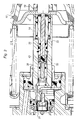
- the brake pedal is connected by a control rod 12 whose front end is shown in FIG. figure 1 , the piston 10 of the booster and a primary piston 14 of a master cylinder 16 of a braking circuit.
- a reinforcing piece 11 integral with the piston 10 of the booster bears on the rear end of the primary piston 14.
- a feeler 18 is mounted axially at the front end of the piston rod. 12 and is intended to act on the rear end of a support ratio control rod 20, which is mounted axially sliding inside a reaction piston 22, itself axially slidably mounted to the inside the rear part of the primary piston 14.
- the primary piston 14 is mounted axially slidably at the rear end of the master cylinder 16 and its front end, housed in a primary chamber 24 of the master cylinder, carries a valve 26 closing a passage communicating with a brake fluid supply channel 28 for isolating the primary chamber 24 of the brake fluid reservoir from the beginning of braking.
- a channel 30 is formed axially at the front end of the primary piston 14 to establish a communication between the primary chamber 24 of the master cylinder and the internal volume of the primary piston 14.
- the reaction piston 22 the assist ratio control rod 20, which passes axially through the reaction piston 22, and a fast piston 32 mounted axially sliding in a sealed manner in a bushing 34 secured to the primary piston 14.
- the fast piston 32 is formed with an axial passage 36 whose front end opens into an internal chamber 38 of the primary piston 14, connected by the channel 30 to the primary chamber 24 of the master cylinder 16.
- the rear end of the passage 36 is closable by a valve 40 carried by the front end of the support ratio control rod 20.
- the forward end of the fast piston 32 is, in the rest position shown in FIG. figure 1 , in abutment on an annular piece 42 forming seat of a return spring 44 whose rear end is supported on the piece 42 and the front end bearing on a portion of the primary piston 14.
- the annular piece 42 is pushed by the spring 44 bearing on the front end of the sleeve 34.
- the rear end of the fast piston 32 which is axially spaced from the rear end of the sleeve 34 in the rest position, comprises an annular flange 46 forming a seat of a return spring 48 mounted between the rear end of the piston 32 and the front end of the support ratio control rod 20, the rear end of the return spring 48 being applied on an annular flange 50 of the front end of the rod 20.
- This annular flange 50 and the front part of the rod 20 have a diameter or external transverse dimension smaller than the internal diameter of the primary piston 14 and greater than the diameter of the cylindrical inner surface of the reaction piston 22, in which the rod 20 is mounted sliding with a seal .
- the front end of the reaction piston 22 is guided in the inner cylindrical surface of the primary piston 14 in a sliding manner and the diameter or the transverse dimension of the front end face of the reaction piston 22 is substantially equal to the diameter or the transverse dimension of the internal cylindrical surface of the primary piston 14.
- a return spring 52 of the reaction piston 22 in its rest position shown in FIG. figure 1 is mounted around the rear portion of this piston, between an outer annular flange 54 formed in the middle part of the piston 22 and a guide ring 56 snap-fitted at the rear end of the primary piston 14 and through which the rear part of the reaction piston 22 passes.
- the axial length of the assist ratio control rod 20 is such that in the rest position shown in FIG. figure 1 , its rear end is projecting axially rearwardly relative to the rear end of the reaction piston 22, and the valve 40 mounted at the front end of the rod 20 is axially spaced from the rear end of the passage 36 formed in the fast piston 32.
- the pressure in the primary chamber 24 is applied to the portion of the front end of the valve 40 which closes the rear end of the passage 36 and can not act on the front end of the reaction piston 22.
- the force resulting from the application of the pressure in the primary chamber 24 on the valve 40 is transmitted by the rod 20 and the probe 18 to the control rod 12 and the brake pedal, but its amplitude is significantly lower than the force feedback that is transmitted to the brake pedal by the reaction piston 22 during a normal braking, the surface of the part of the valve 40 on which the pressure acts during an emergency braking is significantly lower than the surface of the front end of the reaction piston 22 .
- This lower force feedback encourages the driver to maintain the effort it exerts on the brake pedal, which ensures maximum braking efficiency.
- the invention proposes to limit the rearward displacement of the assistance ratio control rod 20 by means 60 which are integral with the primary piston 14 and which extend radially in the internal volume. of this piston, behind the annular flange 50 formed at the front end of the rod 20, these means 60 being a little in front of the front end of the reaction piston 22 in its rest position shown in FIG. figure 1 which is an extreme position before.
- these means 60 are constituted by a split elastic ring which is engaged in a circular groove formed in the internal cylindrical surface of the primary piston 14.
- these means 60 could be constituted by a shoulder of the inner cylindrical surface of the primary piston 14, or by any other means projecting radially inside the primary piston 14 and secured thereto.
- these means 60 could be immobilized in the piston 14 by gluing, screwing, or by any other appropriate means.
- the force exerted by the return spring 48 on the fast piston 32 is less than the force exerted by the return spring 52 on the reaction piston 22.
- the opening of the passage 36 takes place when the reaction piston 22 is already in his rest position represented in figure 1 .
- the rear end of the rod 20 projects rearwardly with respect to the rear end of the reaction piston 22, and remains spaced axially from the probe 18 when the control rod 12 is itself in its rest position.
- the invention is applicable to existing braking devices at the cost of a simple and inexpensive modification and improves braking in emergency situations.
Landscapes
- Engineering & Computer Science (AREA)
- Transportation (AREA)
- Mechanical Engineering (AREA)
- Braking Systems And Boosters (AREA)
- Electric Propulsion And Braking For Vehicles (AREA)
- Braking Arrangements (AREA)
Claims (10)
- Bremsvorrichtung für ein Kraftfahrzeug, die einen pneumatischen Unterstützungsservomotor aufweist, der einem Hauptzylinder (16) zugeordnet ist, bei dem ein Primärkolben (14) von einem Kolben (10) des Servomotors und einer mit einem Bremspedal verbundenen Steuerstange (12) translatorisch bewegt werden kann, um eine Bremskraft zu erzeugen, wobei der Primärkolben (14) eine allgemeine zylindrische Rohrform hat und einen zylindrischen, rohrförmigen Reaktionskolben (22) enthält, der mit einer Rückstellfeder (52) ausgestattet und dazu vorgesehen ist, an seinem hinteren Ende mit einem vorderen Ende der Steuerstange (12) zusammenzuwirken, und eine Stange (20) zur Steuerung des Unterstützungsverhältnisses, die im Reaktionskolben (22) gleitend angebracht ist und ein hinteres Ende, das mit dem vorderen Ende der mit dem Bremspedal verbundenen Steuerstange (12) zusammenwirken soll, sowie ein vorderes Ende hat, das ein Ventilelement (40) zum Verschließen eines Durchgangs (36) aufweist, der in einem im vorderen Bereich des Primärkolbens (14) angebrachten schnellen Kolben (32) ausgebildet ist, wobei dieser Durchgang mit einer Primärkammer (24) des Hauptzylinders verbunden ist, um den in der Primärkammer herrschenden Druck auf das vordere Ende des Reaktionskolbens (22) einwirken zu lassen, wenn das Ventilelement (40) den Durchgang (36) nicht verschließt, dadurch gekennzeichnet, dass sie Mittel (60) aufweist, die die Verlagerung der Stange zur Steuerung des Unterstützungsverhältnisses nach hinten begrenzen und es nach einer Schnellbremsung und einem teilweisen Nachlassen der Bremskraft ermöglichen, das Ventilelement (40) im Wesentlichen bis zum vollständigen Nachlassen der Bremskraft in der Stellung zum Verschließen des Durchgangs (36) zu halten.
- Vorrichtung nach Anspruch 1, dadurch gekennzeichnet, dass die Mittel, die die Verlagerung der Stange (20) zur Steuerung des Unterstützungsverhältnisses nach hinten begrenzen, Anschlagmittel (60) sind, die vom Primärkolben (14) getragen und dazu vorgesehen sind, mit einem Teil der oben genannten Stange (20) zusammenzuwirken.
- Vorrichtung nach Anspruch 2, dadurch gekennzeichnet, dass die Anschlagmittel (60) zwischen dem vorderen Ende des Reaktionskolbens (22) in seiner Ruhestellung und einem vorderen Teil der Stange (20) zur Steuerung des Unterstützungsverhältnisses liegen, wobei dieser vordere Teil eine Aufnahme für das Ventilelement (40) bildet und einen Außendurchmesser hat, der kleiner ist als der Innendurchmesser des Primärkolbens (14).
- Vorrichtung nach Anspruch 2 oder 3, dadurch gekennzeichnet, dass die Anschlagmittel (60) an die Innenfläche des Primärkolbens angesetzt und beispielsweise durch Stecken, Kleben oder Schrauben befestigt sind.
- Vorrichtung nach Anspruch 4, dadurch gekennzeichnet, dass die Anschlagmittel (60) durch einen geschlitzten elastischen Ring gebildet sind, der in eine ringförmige innere Nut des Primärkolbens eingesetzt ist.
- Vorrichtung nach einem der Ansprüche 1 bis 3, dadurch gekennzeichnet, dass die Mittel, die die Verlagerung der Stange (20) zur Steuerung des Unterstützungsverhältnisses nach hinten begrenzen, durch einen Absatz der Innenfläche des Primärkolbens (14) gebildet sind.
- Vorrichtung nach einem der vorhergehenden Ansprüche, dadurch gekennzeichnet, dass zwischen dem vorderen Ende der Stange (20) zur Steuerung des Unterstützungsverhältnisses und dem hinteren Ende des schnellen Kolbens (32) eine Rückstellfeder (48) angebracht ist, um den schnellen Kolben (32) wegzurücken und den Durchgang (36) zu öffnen, wenn die Kraft, die durch den in der Primärkammer (24) des Hauptzylinders herrschenden Druck auf den schnellen Kolben (32) ausgeübt wird, kleiner wird als die Kraft der Rückstellfeder (48).
- Vorrichtung nach Anspruch 7, dadurch gekennzeichnet, dass die Kraft, die von der zwischen dem schnellen Kolben (32) und der Stange (20) zur Steuerung des Unterstützungsverhältnisses angebrachten Rückstellfeder (48) ausgeübt wird, kleiner ist als die Kraft, die auf den Reaktionskolben (22) durch dessen Rückstellfeder (52) ausgeübt wird.
- Vorrichtung nach einem der Ansprüche 2 bis 8, dadurch gekennzeichnet, dass in der Ruhestellung der Vorrichtung die Stange (20) zur Steuerung des Unterstützungsverhältnisses an den Anschlagmitteln (60) anliegt, der schnelle Kolben an seinem vorderen Ende an einem ringförmigen Sitz (42) einer Rückstellfeder (44) in Anschlag ist, die den schnellen Kolben nach hinten beaufschlagt, und der Reaktionskolben (22) von seiner Rückstellfeder (52) so gehalten ist, dass sein vorderes Ende am Primärkolben (14) anliegt.
- Vorrichtung nach einem der vorhergehenden Ansprüche, dadurch gekennzeichnet, dass in der Ruhestellung der Vorrichtung das hintere Ende der Stange (20) zur Steuerung des Unterstützungsverhältnisses vom vorderen Ende der mit dem Bremspedal verbundenen Steuerstange (12) weggerückt ist.
Applications Claiming Priority (3)
| Application Number | Priority Date | Filing Date | Title |
|---|---|---|---|
| FR0102772 | 2001-02-28 | ||
| FR0102772A FR2821314B1 (fr) | 2001-02-28 | 2001-02-28 | Dispositif de freinage pour vehicule automobile |
| PCT/FR2002/000659 WO2002068252A1 (fr) | 2001-02-28 | 2002-02-22 | Dispositif de freinage pour vehicule automobile. |
Publications (2)
| Publication Number | Publication Date |
|---|---|
| EP1365949A1 EP1365949A1 (de) | 2003-12-03 |
| EP1365949B1 true EP1365949B1 (de) | 2008-08-20 |
Family
ID=8860586
Family Applications (1)
| Application Number | Title | Priority Date | Filing Date |
|---|---|---|---|
| EP02706887A Expired - Lifetime EP1365949B1 (de) | 2001-02-28 | 2002-02-22 | Kraftfahrzeugbremsvorrichtung |
Country Status (6)
| Country | Link |
|---|---|
| EP (1) | EP1365949B1 (de) |
| AT (1) | ATE405462T1 (de) |
| DE (1) | DE60228416D1 (de) |
| ES (1) | ES2309151T3 (de) |
| FR (1) | FR2821314B1 (de) |
| WO (1) | WO2002068252A1 (de) |
Family Cites Families (2)
| Publication number | Priority date | Publication date | Assignee | Title |
|---|---|---|---|---|
| FR2756240B1 (fr) * | 1996-11-22 | 1998-12-31 | Bosch Sist De Frenado Sl | Dispositif de freinage assiste a rapport d'assistance variable et hysteresis reduite |
| FR2774345B3 (fr) * | 1998-01-30 | 2000-03-10 | Bosch Syst Freinage | Maitre-cylindre perfectionne a reaction hydraulique dynamiquement annulable |
-
2001
- 2001-02-28 FR FR0102772A patent/FR2821314B1/fr not_active Expired - Fee Related
-
2002
- 2002-02-22 WO PCT/FR2002/000659 patent/WO2002068252A1/fr not_active Ceased
- 2002-02-22 DE DE60228416T patent/DE60228416D1/de not_active Expired - Lifetime
- 2002-02-22 EP EP02706887A patent/EP1365949B1/de not_active Expired - Lifetime
- 2002-02-22 ES ES02706887T patent/ES2309151T3/es not_active Expired - Lifetime
- 2002-02-22 AT AT02706887T patent/ATE405462T1/de not_active IP Right Cessation
Also Published As
| Publication number | Publication date |
|---|---|
| ES2309151T3 (es) | 2008-12-16 |
| WO2002068252A1 (fr) | 2002-09-06 |
| ATE405462T1 (de) | 2008-09-15 |
| FR2821314A1 (fr) | 2002-08-30 |
| FR2821314B1 (fr) | 2003-04-11 |
| EP1365949A1 (de) | 2003-12-03 |
| DE60228416D1 (de) | 2008-10-02 |
Similar Documents
| Publication | Publication Date | Title |
|---|---|---|
| FR2591169A1 (fr) | Generateur de pression de freinage | |
| FR2751602A1 (fr) | Dispositif de freinage assiste a rapport d'assistance variable | |
| EP1542891B1 (de) | Pneumatischer bremskraftverstärker | |
| EP0939713B1 (de) | Hilfskraftbremsvorrichtung mit variablem verstärkerverhältnis und verringerter hysterese | |
| EP1208025B1 (de) | Unterdruckbremskraftverstärker mit selektiver automatischer und kraftgeregelter unterstützung | |
| EP0779868B1 (de) | Bremsanlage mit erhöhter sicherheit | |
| EP1457400B1 (de) | Bremskraftvorrichtung mit verbesserter Bremsempfindlichkeit | |
| EP1365949B1 (de) | Kraftfahrzeugbremsvorrichtung | |
| EP0993399B1 (de) | Hauptzylinder mit dynamischer hydraulischer reaktion und mit schwimmendem kolben | |
| EP1351849B1 (de) | Servomotor für notbremse mit mitteln zur verriegelung durch ein radiales hindernis | |
| EP1064180B1 (de) | Pneumatischer bremskraftverstärker mit in position gesteuerter selbstverstärkung | |
| FR2586983A1 (fr) | Systeme de freinage a regulation du glissement | |
| EP1305197B1 (de) | Bremskraftverstärker für eine notbremshilfe mit schalldämmungsmittel | |
| FR2773347A1 (fr) | Servofrein et systeme de freinage le comportant | |
| EP0814987B1 (de) | Bremskraftverstärker mit vorfüllung ohne durchflussbegrenzung | |
| FR2809066A1 (fr) | Servomoteur comportant un embrayage unidirectionnel expansible | |
| EP1097073B1 (de) | Verbesserter hauptzylinder mit hydraulischer reaktion und selektiver selbstverstärkung | |
| EP1339584B1 (de) | Bremskraftverstärkervorrichtung mit verbesserten betriebsbedingungen für kraftfahrzeug | |
| EP2465742B1 (de) | Pneumatischer Hilfsservomotor zum Bremsen eines Fahrzeugs mit Empfindungserhaltung am Bremspedal | |
| EP1124715B1 (de) | Unterdruckbremskraftverstärker mit automatischer unterstützung | |
| WO2002087943A2 (fr) | Dispositif de freinage a rattrapage de courses mortes, en particulier pour vehicule automobile | |
| WO2002096731A1 (fr) | Dispositif de freinage pour vehicule automobile | |
| FR2855135A1 (fr) | Servomoteur d'assistance pneumatique au freinage | |
| FR2825056A1 (fr) | Servomoteur d'assistance pneumatique au freinage a hauteur de saut variable | |
| FR2848965A1 (fr) | Servomoteur d'assistance pneumatique de freinage d'un vehicule muni d'un dispositif d'asservissement mecanique supplementaire |
Legal Events
| Date | Code | Title | Description |
|---|---|---|---|
| PUAI | Public reference made under article 153(3) epc to a published international application that has entered the european phase |
Free format text: ORIGINAL CODE: 0009012 |
|
| 17P | Request for examination filed |
Effective date: 20030929 |
|
| AK | Designated contracting states |
Kind code of ref document: A1 Designated state(s): AT BE CH CY DE DK ES FI FR GB GR IE IT LI LU MC NL PT SE TR |
|
| AX | Request for extension of the european patent |
Extension state: AL LT LV MK RO SI |
|
| GRAP | Despatch of communication of intention to grant a patent |
Free format text: ORIGINAL CODE: EPIDOSNIGR1 |
|
| GRAS | Grant fee paid |
Free format text: ORIGINAL CODE: EPIDOSNIGR3 |
|
| GRAA | (expected) grant |
Free format text: ORIGINAL CODE: 0009210 |
|
| AK | Designated contracting states |
Kind code of ref document: B1 Designated state(s): AT BE CH CY DE DK ES FI FR GB GR IE IT LI LU MC NL PT SE TR |
|
| REG | Reference to a national code |
Ref country code: GB Ref legal event code: FG4D Free format text: NOT ENGLISH |
|
| REG | Reference to a national code |
Ref country code: CH Ref legal event code: EP |
|
| REG | Reference to a national code |
Ref country code: IE Ref legal event code: FG4D Free format text: LANGUAGE OF EP DOCUMENT: FRENCH |
|
| REF | Corresponds to: |
Ref document number: 60228416 Country of ref document: DE Date of ref document: 20081002 Kind code of ref document: P |
|
| REG | Reference to a national code |
Ref country code: ES Ref legal event code: FG2A Ref document number: 2309151 Country of ref document: ES Kind code of ref document: T3 |
|
| PG25 | Lapsed in a contracting state [announced via postgrant information from national office to epo] |
Ref country code: NL Free format text: LAPSE BECAUSE OF FAILURE TO SUBMIT A TRANSLATION OF THE DESCRIPTION OR TO PAY THE FEE WITHIN THE PRESCRIBED TIME-LIMIT Effective date: 20080820 |
|
| PG25 | Lapsed in a contracting state [announced via postgrant information from national office to epo] |
Ref country code: AT Free format text: LAPSE BECAUSE OF FAILURE TO SUBMIT A TRANSLATION OF THE DESCRIPTION OR TO PAY THE FEE WITHIN THE PRESCRIBED TIME-LIMIT Effective date: 20080820 Ref country code: FI Free format text: LAPSE BECAUSE OF FAILURE TO SUBMIT A TRANSLATION OF THE DESCRIPTION OR TO PAY THE FEE WITHIN THE PRESCRIBED TIME-LIMIT Effective date: 20080820 |
|
| REG | Reference to a national code |
Ref country code: IE Ref legal event code: FD4D |
|
| PG25 | Lapsed in a contracting state [announced via postgrant information from national office to epo] |
Ref country code: DK Free format text: LAPSE BECAUSE OF FAILURE TO SUBMIT A TRANSLATION OF THE DESCRIPTION OR TO PAY THE FEE WITHIN THE PRESCRIBED TIME-LIMIT Effective date: 20080820 Ref country code: IE Free format text: LAPSE BECAUSE OF FAILURE TO SUBMIT A TRANSLATION OF THE DESCRIPTION OR TO PAY THE FEE WITHIN THE PRESCRIBED TIME-LIMIT Effective date: 20080820 |
|
| PG25 | Lapsed in a contracting state [announced via postgrant information from national office to epo] |
Ref country code: PT Free format text: LAPSE BECAUSE OF FAILURE TO SUBMIT A TRANSLATION OF THE DESCRIPTION OR TO PAY THE FEE WITHIN THE PRESCRIBED TIME-LIMIT Effective date: 20090120 |
|
| PLBE | No opposition filed within time limit |
Free format text: ORIGINAL CODE: 0009261 |
|
| STAA | Information on the status of an ep patent application or granted ep patent |
Free format text: STATUS: NO OPPOSITION FILED WITHIN TIME LIMIT |
|
| 26N | No opposition filed |
Effective date: 20090525 |
|
| BERE | Be: lapsed |
Owner name: ROBERT BOSCH G.M.B.H. Effective date: 20090228 |
|
| PG25 | Lapsed in a contracting state [announced via postgrant information from national office to epo] |
Ref country code: MC Free format text: LAPSE BECAUSE OF NON-PAYMENT OF DUE FEES Effective date: 20090228 |
|
| REG | Reference to a national code |
Ref country code: CH Ref legal event code: PL |
|
| PG25 | Lapsed in a contracting state [announced via postgrant information from national office to epo] |
Ref country code: LI Free format text: LAPSE BECAUSE OF NON-PAYMENT OF DUE FEES Effective date: 20090228 Ref country code: CH Free format text: LAPSE BECAUSE OF NON-PAYMENT OF DUE FEES Effective date: 20090228 |
|
| PG25 | Lapsed in a contracting state [announced via postgrant information from national office to epo] |
Ref country code: SE Free format text: LAPSE BECAUSE OF FAILURE TO SUBMIT A TRANSLATION OF THE DESCRIPTION OR TO PAY THE FEE WITHIN THE PRESCRIBED TIME-LIMIT Effective date: 20081120 |
|
| PG25 | Lapsed in a contracting state [announced via postgrant information from national office to epo] |
Ref country code: BE Free format text: LAPSE BECAUSE OF NON-PAYMENT OF DUE FEES Effective date: 20090228 |
|
| PG25 | Lapsed in a contracting state [announced via postgrant information from national office to epo] |
Ref country code: GR Free format text: LAPSE BECAUSE OF FAILURE TO SUBMIT A TRANSLATION OF THE DESCRIPTION OR TO PAY THE FEE WITHIN THE PRESCRIBED TIME-LIMIT Effective date: 20081121 |
|
| PG25 | Lapsed in a contracting state [announced via postgrant information from national office to epo] |
Ref country code: LU Free format text: LAPSE BECAUSE OF NON-PAYMENT OF DUE FEES Effective date: 20090222 |
|
| PG25 | Lapsed in a contracting state [announced via postgrant information from national office to epo] |
Ref country code: TR Free format text: LAPSE BECAUSE OF FAILURE TO SUBMIT A TRANSLATION OF THE DESCRIPTION OR TO PAY THE FEE WITHIN THE PRESCRIBED TIME-LIMIT Effective date: 20080820 |
|
| PG25 | Lapsed in a contracting state [announced via postgrant information from national office to epo] |
Ref country code: CY Free format text: LAPSE BECAUSE OF FAILURE TO SUBMIT A TRANSLATION OF THE DESCRIPTION OR TO PAY THE FEE WITHIN THE PRESCRIBED TIME-LIMIT Effective date: 20080820 |
|
| PGFP | Annual fee paid to national office [announced via postgrant information from national office to epo] |
Ref country code: FR Payment date: 20140218 Year of fee payment: 13 |
|
| REG | Reference to a national code |
Ref country code: FR Ref legal event code: ST Effective date: 20151030 |
|
| PG25 | Lapsed in a contracting state [announced via postgrant information from national office to epo] |
Ref country code: FR Free format text: LAPSE BECAUSE OF NON-PAYMENT OF DUE FEES Effective date: 20150302 |
|
| PGFP | Annual fee paid to national office [announced via postgrant information from national office to epo] |
Ref country code: IT Payment date: 20160222 Year of fee payment: 15 Ref country code: ES Payment date: 20160223 Year of fee payment: 15 |
|
| PGFP | Annual fee paid to national office [announced via postgrant information from national office to epo] |
Ref country code: GB Payment date: 20160222 Year of fee payment: 15 |
|
| PGFP | Annual fee paid to national office [announced via postgrant information from national office to epo] |
Ref country code: DE Payment date: 20160426 Year of fee payment: 15 |
|
| REG | Reference to a national code |
Ref country code: DE Ref legal event code: R119 Ref document number: 60228416 Country of ref document: DE |
|
| GBPC | Gb: european patent ceased through non-payment of renewal fee |
Effective date: 20170222 |
|
| PG25 | Lapsed in a contracting state [announced via postgrant information from national office to epo] |
Ref country code: DE Free format text: LAPSE BECAUSE OF NON-PAYMENT OF DUE FEES Effective date: 20170901 |
|
| PG25 | Lapsed in a contracting state [announced via postgrant information from national office to epo] |
Ref country code: GB Free format text: LAPSE BECAUSE OF NON-PAYMENT OF DUE FEES Effective date: 20170222 Ref country code: IT Free format text: LAPSE BECAUSE OF NON-PAYMENT OF DUE FEES Effective date: 20170222 |
|
| REG | Reference to a national code |
Ref country code: ES Ref legal event code: FD2A Effective date: 20180705 |
|
| PG25 | Lapsed in a contracting state [announced via postgrant information from national office to epo] |
Ref country code: ES Free format text: LAPSE BECAUSE OF NON-PAYMENT OF DUE FEES Effective date: 20170223 |