EP2465745B1 - Dispositif d'actionnement mécanique - Google Patents
Dispositif d'actionnement mécanique Download PDFInfo
- Publication number
- EP2465745B1 EP2465745B1 EP11192334.8A EP11192334A EP2465745B1 EP 2465745 B1 EP2465745 B1 EP 2465745B1 EP 11192334 A EP11192334 A EP 11192334A EP 2465745 B1 EP2465745 B1 EP 2465745B1
- Authority
- EP
- European Patent Office
- Prior art keywords
- lever
- switching position
- switching
- actuator
- switching element
- Prior art date
- Legal status (The legal status is an assumption and is not a legal conclusion. Google has not performed a legal analysis and makes no representation as to the accuracy of the status listed.)
- Active
Links
Images


Classifications
-
- B—PERFORMING OPERATIONS; TRANSPORTING
- B61—RAILWAYS
- B61C—LOCOMOTIVES; MOTOR RAILCARS
- B61C17/00—Arrangement or disposition of parts; Details or accessories not otherwise provided for; Use of control gear and control systems
- B61C17/04—Arrangement or disposition of driving cabins, footplates or engine rooms; Ventilation thereof
-
- F—MECHANICAL ENGINEERING; LIGHTING; HEATING; WEAPONS; BLASTING
- F16—ENGINEERING ELEMENTS AND UNITS; GENERAL MEASURES FOR PRODUCING AND MAINTAINING EFFECTIVE FUNCTIONING OF MACHINES OR INSTALLATIONS; THERMAL INSULATION IN GENERAL
- F16P—SAFETY DEVICES IN GENERAL; SAFETY DEVICES FOR PRESSES
- F16P3/00—Safety devices acting in conjunction with the control or operation of a machine; Control arrangements requiring the simultaneous use of two or more parts of the body
- F16P3/08—Safety devices acting in conjunction with the control or operation of a machine; Control arrangements requiring the simultaneous use of two or more parts of the body in connection with the locking of doors, covers, guards, or like members giving access to moving machine parts
-
- H—ELECTRICITY
- H01—ELECTRIC ELEMENTS
- H01H—ELECTRIC SWITCHES; RELAYS; SELECTORS; EMERGENCY PROTECTIVE DEVICES
- H01H3/00—Mechanisms for operating contacts
- H01H3/02—Operating parts, i.e. for operating driving mechanism by a mechanical force external to the switch
- H01H3/20—Operating parts, i.e. for operating driving mechanism by a mechanical force external to the switch wherein an auxiliary movement thereof, or of an attachment thereto, is necessary before the main movement is possible or effective, e.g. for unlatching, for coupling
Definitions
- the invention relates to a mechanical actuating device, in particular for a functional assembly of a rail vehicle, comprising a rotatably mounted about an axis of rotation lever which is movable between at least a first switching position and a second switching position back and forth, operatively connected to the lever switching element, which between a first Switching position and a second switching position is movable back and forth, wherein a switching movement of the lever from the first switching position to the second switching position causes a change in the switching position of the switching element, wherein a switch is provided, the between a first position and a second position back and forth is movable, and wherein the movement of the lever from the first switching position to the second switching position causes a change in the switching position of the switching element from the first switching position to the second switching position only if the switch in the first Stellu ng is.
- a generic mechanical actuator is from the DE 30 23 033 A1 known.
- the mechanical actuating device 10 comprises a switching element 14 with an actuator 20 which can be moved in an actuating direction 22.
- the actuator 20 may, for example, be a valve tappet which opens or closes the switching element 14 designed as a valve by displacement along the actuating direction 22.
- the movement of the actuator 20 via a lever 12 which is rigid is coupled with a cam profile 26 having a cam 24.
- the lever 12 with the cam 24 is rotatably supported about a rotation axis 18.
- the rotation of the lever 12 is transmitted to an actuating lever 32, wherein the actuating lever 32 is fixed relative to the switching element 14 by a fixing 40 and is rotatably mounted about a further axis of rotation 30.
- the actuating lever 32 is rotated about the further axis of rotation 30 due to the cam profile 26, so that the actuator 20 is displaced by the actuating lever along the actuating direction 22.
- the cam profile 26 has notches in its upper region and in its lower region, which correspond to a first switching position of the lever and to a second switching position of the lever.
- the switching element 14 is coupled via a coupling 44 with a further switching element 14 '.
- the further switching element 14 ' comprises a further actuator 20', which, just like the actuator 20 of the switching element 14 along the operating direction 22 for opening and closing the further switching element 14 'is movable.
- the further switching element 14 ' can be designed as a valve which can be opened and closed by the further actuator 20' designed as a valve tappet.
- the coupling 44 between the switching element 14 and the further switching element 14 ' may in particular comprise a casing, wherein, for example, an output of the switching element 14 is coupled to an input of the further switching element 14'.
- the actuation of the further actuator 20 ' takes place via a further lever arm 34 which is rotatably fixed about an additional rotation axis 36 by means of a further fixation 40' relative to the further switching element 14 '.
- the further lever arm is rotated by operating a connected to an actuator 28 switch 16 to the additional axis of rotation 36, wherein the further actuator 20 'along the actuating direction 22 is moved and the other switching element 14' opens
- Both the switching element 14 and the further switching element 14 ' may represent, for example, 2/2-way valves, wherein the output of the switching element 14 with the input of the further switching element 14' through the coupling 44th connected is. Accordingly, both the switching element 14 and the further switching element 14 'each have a first switching position and a second switching position. In the first switching position, the switching element 14 and the further switching element 14 'in their respective blocking position and in the second switching position in their respective passage position. Accordingly, the mechanical actuator 10 is entirely in its on-position when both the switching element 14 and the further switching element 14 'are in their respective pass-through positions, that is, in their respective second switching positions. To accomplish this, the lever 12 must be in the second position, while the switch 16 is in the second position.
- the mechanical actuator 10 therefore provides a total of a switchable actuator in the form of a switchable actuating lever ready.
- a functional module (not shown) connected to an output connection (also not shown), for example a pressure-medium-operated door opener, can be controlled, wherein, for example, compressed air can be used as the pressure medium.
- the present invention provides a mechanical actuator that requires less space with identical functionality and at the same time has a simpler design.
- the present invention has for its object to provide a mechanical actuator in which the operation is possible with one hand by the mutually time independent actuation of lever and switch.
- a switch which is reciprocable between a first position and a second position, wherein the movement of the lever from the first switching position to the second switching position, a change in the switching position of the switching element from the first switching position to the second Switching position only effected when the switch is in the first position.
- the further switching element can be completely saved with the other actuator, without thereby sacrificing the functionality of the overall device occur.
- a simpler mechanical design of the actuator results. As a result, both a reduction in size and a reduction in the construction cost of the actuator is achieved. Furthermore, the risk of leakage is reduced because the coupling between the separate switching elements can be omitted, which is why there are fewer sealing points.
- the lever is rotatably supported about a rotation axis.
- a rotatable bearing of the lever allows easy operation of the lever. Instead of a rotational movement, however, a shift of the lever may be provided.
- an actuator of the switching element is moved in an actuating direction in order to transfer the switching element from the first switching position to the second switching position.
- An axial displacement of the actuator provides a simple way to operate the switching element.
- a cam with a cam profile is rigidly coupled or via a gear with the lever and rotatably supported about the axis of rotation. Using the cam profile of the cam, the rotational movement of the lever between its first switching position and its second switching position is converted into a resulting movement of the cam profile scanning component.
- the switch comprises a movable by operating the switch actuator, and that is moved by moving the actuator, a further axis of rotation of an actuating lever relative to the switching element. In this way, further moving parts can be completely saved.
- a further lever arm is provided, which is rotatably coupled to the further rotation axis with the actuating lever, and that the further lever arm relative to the switching element is rotatably fixed to an additional rotation axis. In this way, the complexity of the actuator in the region of the switch and the axes of rotation can be kept low.
- FIG. 1 shows a mechanical actuator according to the prior art, which has already been described in the introduction.
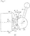
- FIG. 2 shows a mechanical actuator according to the invention in a first position.
- the illustrated mechanical actuator 10 comprises as actuators a lever 12 and a switch 16.
- the lever 12 and the switch 16 act together on an actuator 20, which is displaceable in an actuating direction 22.
- the actuator 20 may be a valve tappet of a switching element 14 designed as a valve.
- the switching element 14 may in particular be designed as a simple 2/2-way valve that can be switched by the actuator 20 between its open and its closed position.
- a first switching position of the switching element 14 and the actuator 20 corresponds to the closed position of the switching element 14 while a second switching position of the switching element 14 and the actuator 20 corresponds to an open position of the switching element 14.
- In the first switching position of the switching element 14 is a in the FIG.
- a lever 12 is as in the off FIG. 1 known embodiment rigidly coupled to a cam 24, which has a cam profile 26, and rotatably mounted about a rotation axis 18.
- the lever 12 may be coupled via a gear to the cam 24.
- the cam profile 26 is scanned by a voltage applied to the cam 24 roller 42, the cam profile 26 in a corresponding movement of a Operating lever 32 implements.
- the cam profile 26 has two notches, which correlate with the first switching position and the second switching position of the lever 12.
- the lever arm of the actuating lever 32 slidably abuts against the actuator 20, so that a rotation of the lever arm about a further axis of rotation 30 can lead to a displacement of the actuator 20 in an actuating direction 22.
- the remote from the roller 42 end of the actuating lever 32 is rotatably mounted about the further axis of rotation 30.
- a further lever arm 34 is also rotatably coupled to the further rotation axis 30 and at the same time rotatably connected to the additional rotation axis 36 which is fixed via a fixing 40 relative to the switching element 14.
- the switch 16 which is rigidly connected to an actuator 28, is adapted to displace the further rotation axis 30 substantially in the actuation direction 22 against a spring force applied by a spring 38.
- the actuator 28 may rest directly on the further axis of rotation 30, the actuating lever 32 or the further lever arm 34.
- the actuator 28 is coupled directly to the further rotation axis 30 and fixes it.
- the spring 38 and / or the further lever arm 34 can be dispensed with in order to further simplify the mechanical actuating device 10.
- the spring 38 may, as in FIG. 2 shown to be designed as a spiral spring. However, it is also conceivable that the spring 38 acts as a torsion spring on the additional axis of rotation 36 and from there presses the further lever arm 34 against the actuator 28.
- the switch 16 is in its first position, so that the further axis of rotation 30 in the operating direction 22 is far away from the switching element 14. Due to this large distance of the further axis of rotation 30, the transmitted to the actuator 20 by the operating lever 32 and the cam profile 26 displacement in the operating direction 22 when turning the lever 12 from the first switching position to the second switching position is not sufficient to the switching element 14 from his closed state in its open state to convict. It is even conceivable that the operating lever 32 completely from the actuator 20 is lifted when the lever is in the first switching position.
- a torsion spring may be provided on the further axis of rotation 30, which presses the actuating lever 32 against the cam profile 26.
- FIG. 3 shows a mechanical actuator according to the invention in a second position.
- mechanical actuator 10 corresponds to the FIG. 2 already known mechanical actuator 10, wherein, however, the switch 16 is shown in the second position. Accordingly, the further axis of rotation 30 under the action of the actuator 28 against the representation FIG. 2 closer to the switching element 14 so that the actuator 20 when operating the lever 12 from the first switching position to the second switching position, the switching element 14 transferred from the closed state to the open state.
- the cam profile 26 acts directly on the actuator 20, in which case the operating lever 32 and a possibly existing lever arm 34 may be omitted.
- the cam profile 26 is to be adapted accordingly, that is, it should extend from a notch to an elevation, wherein the notch correlates with the first switching position of the lever and correlates the increase with the second switching position of the lever.
- the switch 16 should continue to be able to displace the axis of rotation 18 in the direction of actuation 22 with respect to the switching element 14 in this unclaimed embodiment.
- the actuator 28 engage the axis of rotation 18 or be fixedly connected to this for fixing.
- the switching element 14 by actuation of the switch 16 by means of the actuator 28 relative to the axis of rotation 18 is displaceable.
Landscapes
- Engineering & Computer Science (AREA)
- Mechanical Engineering (AREA)
- General Engineering & Computer Science (AREA)
- Automation & Control Theory (AREA)
- Transportation (AREA)
- Mechanically-Actuated Valves (AREA)
- Gear-Shifting Mechanisms (AREA)
Claims (5)
- Dispositif (10) mécanique d'actionnement, notamment pour un module d'un véhicule ferroviaire, comprenant- un levier (12), qui est monté pivotant autour d'un axe (18) de pivotement et qui peut aller et venir entre au moins une première position de manoeuvre et une deuxième position de manoeuvre,- un élément (14) de manoeuvre, qui coopère avec le levier (12) et qui peut aller et venir entre une première position de manoeuvre et une deuxième position de manoeuvre,- dans lequel un passage du levier (12), de la première position de manoeuvre à la deuxième position de manoeuvre, provoque une modification de la position de manoeuvre de l'élément (14) de manoeuvre,- dans lequel il est prévu un interrupteur (16), qui peut aller et venir entre une première position et une deuxième position et- dans lequel le passage du levier (12), de la première position de manoeuvre à la deuxième position de manoeuvre, ne provoque une modification de la position de manoeuvre de l'élément (14) de manoeuvre, de la première position de manoeuvre à la deuxième position de manoeuvre, que si l'interrupteur (16) est dans la première position,caractérisé- en ce qu'une came (24), ayant un profil (26), est couplée rigidement ou par une transmission au levier (12) et est montée tournante autour de l'axe (18) de pivotement,- dans lequel le mouvement du levier (12), autour de l'axe (18) de pivotement, entre la première position de manoeuvre et la deuxième position de manoeuvre, est transformé en un déplacement d'une pièce balayant le profil (26) de la came et- en ce que le profil (26) de la came a deux encoches, qui sont en corrélation avec la première position de manoeuvre et la deuxième position de manoeuvre du levier (12).
- Dispositif (10) mécanique d'actionnement suivant la revendication 1, caractérisé en ce qu'un actionneur (20) de l'élément (14) de commutation est déplacé dans un sens (22) d'actionnement, pour faire passer l'élément (14) de manoeuvre, de la première position de manoeuvre à la deuxième position de manoeuvre.
- Dispositif (10) suivant la revendication 1 ou 2, caractérisé- en ce que l'interrupteur (16) comprend un actionneur (28) pouvant être déplacé par l'actionnement de l'interrupteur (16) et- en ce que, par le déplacement de l'actionneur (28), un autre axe (30) de pivotement d'un levier (32) d'actionnement est déplacé par rapport à l'élément (14) de manoeuvre.
- Dispositif (10) suivant la revendication 3, caractérisé- en ce qu'il est prévu un autre bras (34) de levier, qui est couplé en pivotement au levier (32) d'actionnement, sur l'autre axe (30) de pivotement et- en ce que l'autre bras (34) de levier est fixé, avec possibilité de tourner, par rapport à l'élément (14) de manoeuvre, à un axe (36) de pivotement supplémentaire.
- Dispositif (10) suivant la revendication 3 ou 4, caractérisé en ce qu'il est prévu un ressort (38), qui pousse l'autre axe (30) de pivotement sur l'actionneur (28).
Applications Claiming Priority (1)
| Application Number | Priority Date | Filing Date | Title |
|---|---|---|---|
| DE102010054724A DE102010054724A1 (de) | 2010-12-16 | 2010-12-16 | Mechanische Betätigungsvorrichtung |
Publications (2)
| Publication Number | Publication Date |
|---|---|
| EP2465745A1 EP2465745A1 (fr) | 2012-06-20 |
| EP2465745B1 true EP2465745B1 (fr) | 2017-07-05 |
Family
ID=45318913
Family Applications (1)
| Application Number | Title | Priority Date | Filing Date |
|---|---|---|---|
| EP11192334.8A Active EP2465745B1 (fr) | 2010-12-16 | 2011-12-07 | Dispositif d'actionnement mécanique |
Country Status (2)
| Country | Link |
|---|---|
| EP (1) | EP2465745B1 (fr) |
| DE (1) | DE102010054724A1 (fr) |
Cited By (1)
| Publication number | Priority date | Publication date | Assignee | Title |
|---|---|---|---|---|
| EP4160076A1 (fr) * | 2021-10-01 | 2023-04-05 | Nordischer Maschinenbau Rud. Baader Gmbh + Co Kg | Dispositif de traitement de produits |
Families Citing this family (2)
| Publication number | Priority date | Publication date | Assignee | Title |
|---|---|---|---|---|
| AT513718B1 (de) * | 2012-12-05 | 2014-10-15 | Hargassner Gmbh | Sicherheitsvorrichtung |
| DE102018117162B4 (de) | 2018-07-16 | 2020-03-26 | Bombardier Transportation Gmbh | Fahrschalteranordnung für ein Schienenfahrzeug, Schienenfahrzeug mit einer Fahrschalteranordnung und Verwendung eines Gelenklagers in einer Fahrschalteranordnung |
Family Cites Families (3)
| Publication number | Priority date | Publication date | Assignee | Title |
|---|---|---|---|---|
| DE3023033C2 (de) * | 1980-06-20 | 1987-03-26 | Metabowerke GmbH & Co, 7440 Nürtingen | Elektromotorisch angetriebenes Handwerkzeug |
| GB9224660D0 (en) * | 1992-11-25 | 1993-01-13 | Black & Decker Inc | Improved switch mechanism |
| US6548776B1 (en) * | 2002-04-12 | 2003-04-15 | Jenn Feng Industrial Co., Ltd. | Safety device for on/off switch of an electric tool |
-
2010
- 2010-12-16 DE DE102010054724A patent/DE102010054724A1/de not_active Withdrawn
-
2011
- 2011-12-07 EP EP11192334.8A patent/EP2465745B1/fr active Active
Non-Patent Citations (1)
| Title |
|---|
| None * |
Cited By (2)
| Publication number | Priority date | Publication date | Assignee | Title |
|---|---|---|---|---|
| EP4160076A1 (fr) * | 2021-10-01 | 2023-04-05 | Nordischer Maschinenbau Rud. Baader Gmbh + Co Kg | Dispositif de traitement de produits |
| WO2023051985A1 (fr) * | 2021-10-01 | 2023-04-06 | Nordischer Maschinenbau Rud. Baader Gmbh + Co. Kg | Dispositif de traitement de produits |
Also Published As
| Publication number | Publication date |
|---|---|
| EP2465745A1 (fr) | 2012-06-20 |
| DE102010054724A1 (de) | 2012-06-21 |
Similar Documents
| Publication | Publication Date | Title |
|---|---|---|
| EP1986874B2 (fr) | Dispositif a soupape pour la modification manuelle du niveau d'un vehicule dote d'une suspension pneumatique | |
| EP2147219B1 (fr) | Dispositif de blocage avec liquide à champ réglable | |
| EP1489252B1 (fr) | Serrure de porte pour véhicule automobile | |
| DE102016214682A1 (de) | Sperranordnung | |
| DE102007055847A1 (de) | Servounterstützungseinrichtung für Kraftfahrzeug-Wechselgetriebe | |
| EP2465745B1 (fr) | Dispositif d'actionnement mécanique | |
| EP3332099A1 (fr) | Distribution pour un moteur à combustion interne | |
| DE202008012536U1 (de) | Steuerantrieb für ein Kraftfahrzeugschloß | |
| DE102018106015A1 (de) | Kraftfahrzeug-Bowdenzuganordnung | |
| DE102017115191A1 (de) | Ventil, insbesondere Servoventil | |
| DE102018106016A1 (de) | Kraftfahrzeug-Antriebsanordnung | |
| DE102016119812A1 (de) | Elektromotorische Stellvorrichtung | |
| DE102013226148A1 (de) | Hydraulische Türbetätigung mit einem Rollmembranzylinder | |
| WO2021089218A1 (fr) | Embrayage à friction conique doté d'un actionneur et d'un levier pour débrayer l'embrayage | |
| EP1717472B1 (fr) | Dispositif de commande avec un levier balancant, en particulier pour un embrayage | |
| AT504957B1 (de) | Wegeventil, sowie ventilanordnung | |
| DE4107724C2 (fr) | ||
| DE10310930A1 (de) | Aktuatorsystem | |
| EP2829676A2 (fr) | Deux commandes hydrauliques indépendantes ou plus de serrure | |
| DE102020204243A1 (de) | Betätigungsvorrichtung zur Betätigung einer Vorrichtung eines Kraftfahrzeugs | |
| EP1580360B1 (fr) | Actionneur pour véhicules automobiles | |
| DE102011017763A1 (de) | Schaltvorrichtung eines Getriebes | |
| DE102024114431A1 (de) | Kraftfahrzeug-Schloss | |
| DE102020109245A1 (de) | Getränkezubereitungsvorrichtung mit Membranventil | |
| WO2024041698A1 (fr) | Serrure de véhicule automobile |
Legal Events
| Date | Code | Title | Description |
|---|---|---|---|
| PUAI | Public reference made under article 153(3) epc to a published international application that has entered the european phase |
Free format text: ORIGINAL CODE: 0009012 |
|
| AK | Designated contracting states |
Kind code of ref document: A1 Designated state(s): AL AT BE BG CH CY CZ DE DK EE ES FI FR GB GR HR HU IE IS IT LI LT LU LV MC MK MT NL NO PL PT RO RS SE SI SK SM TR |
|
| AX | Request for extension of the european patent |
Extension state: BA ME |
|
| RAP1 | Party data changed (applicant data changed or rights of an application transferred) |
Owner name: KNORR-BREMSE SYSTEME FUER SCHIENENFAHRZEUGE GMBH |
|
| 17P | Request for examination filed |
Effective date: 20121220 |
|
| 17Q | First examination report despatched |
Effective date: 20140305 |
|
| GRAP | Despatch of communication of intention to grant a patent |
Free format text: ORIGINAL CODE: EPIDOSNIGR1 |
|
| INTG | Intention to grant announced |
Effective date: 20170223 |
|
| GRAS | Grant fee paid |
Free format text: ORIGINAL CODE: EPIDOSNIGR3 |
|
| GRAA | (expected) grant |
Free format text: ORIGINAL CODE: 0009210 |
|
| AK | Designated contracting states |
Kind code of ref document: B1 Designated state(s): AL AT BE BG CH CY CZ DE DK EE ES FI FR GB GR HR HU IE IS IT LI LT LU LV MC MK MT NL NO PL PT RO RS SE SI SK SM TR |
|
| REG | Reference to a national code |
Ref country code: GB Ref legal event code: FG4D Free format text: NOT ENGLISH |
|
| REG | Reference to a national code |
Ref country code: CH Ref legal event code: EP |
|
| REG | Reference to a national code |
Ref country code: AT Ref legal event code: REF Ref document number: 906375 Country of ref document: AT Kind code of ref document: T Effective date: 20170715 |
|
| REG | Reference to a national code |
Ref country code: IE Ref legal event code: FG4D Free format text: LANGUAGE OF EP DOCUMENT: GERMAN |
|
| REG | Reference to a national code |
Ref country code: DE Ref legal event code: R096 Ref document number: 502011012543 Country of ref document: DE |
|
| REG | Reference to a national code |
Ref country code: NL Ref legal event code: MP Effective date: 20170705 |
|
| REG | Reference to a national code |
Ref country code: LT Ref legal event code: MG4D |
|
| REG | Reference to a national code |
Ref country code: FR Ref legal event code: PLFP Year of fee payment: 7 |
|
| PG25 | Lapsed in a contracting state [announced via postgrant information from national office to epo] |
Ref country code: HR Free format text: LAPSE BECAUSE OF FAILURE TO SUBMIT A TRANSLATION OF THE DESCRIPTION OR TO PAY THE FEE WITHIN THE PRESCRIBED TIME-LIMIT Effective date: 20170705 Ref country code: NO Free format text: LAPSE BECAUSE OF FAILURE TO SUBMIT A TRANSLATION OF THE DESCRIPTION OR TO PAY THE FEE WITHIN THE PRESCRIBED TIME-LIMIT Effective date: 20171005 Ref country code: NL Free format text: LAPSE BECAUSE OF FAILURE TO SUBMIT A TRANSLATION OF THE DESCRIPTION OR TO PAY THE FEE WITHIN THE PRESCRIBED TIME-LIMIT Effective date: 20170705 Ref country code: FI Free format text: LAPSE BECAUSE OF FAILURE TO SUBMIT A TRANSLATION OF THE DESCRIPTION OR TO PAY THE FEE WITHIN THE PRESCRIBED TIME-LIMIT Effective date: 20170705 Ref country code: SE Free format text: LAPSE BECAUSE OF FAILURE TO SUBMIT A TRANSLATION OF THE DESCRIPTION OR TO PAY THE FEE WITHIN THE PRESCRIBED TIME-LIMIT Effective date: 20170705 Ref country code: LT Free format text: LAPSE BECAUSE OF FAILURE TO SUBMIT A TRANSLATION OF THE DESCRIPTION OR TO PAY THE FEE WITHIN THE PRESCRIBED TIME-LIMIT Effective date: 20170705 |
|
| PG25 | Lapsed in a contracting state [announced via postgrant information from national office to epo] |
Ref country code: BG Free format text: LAPSE BECAUSE OF FAILURE TO SUBMIT A TRANSLATION OF THE DESCRIPTION OR TO PAY THE FEE WITHIN THE PRESCRIBED TIME-LIMIT Effective date: 20171005 Ref country code: RS Free format text: LAPSE BECAUSE OF FAILURE TO SUBMIT A TRANSLATION OF THE DESCRIPTION OR TO PAY THE FEE WITHIN THE PRESCRIBED TIME-LIMIT Effective date: 20170705 Ref country code: PL Free format text: LAPSE BECAUSE OF FAILURE TO SUBMIT A TRANSLATION OF THE DESCRIPTION OR TO PAY THE FEE WITHIN THE PRESCRIBED TIME-LIMIT Effective date: 20170705 Ref country code: GR Free format text: LAPSE BECAUSE OF FAILURE TO SUBMIT A TRANSLATION OF THE DESCRIPTION OR TO PAY THE FEE WITHIN THE PRESCRIBED TIME-LIMIT Effective date: 20171006 Ref country code: LV Free format text: LAPSE BECAUSE OF FAILURE TO SUBMIT A TRANSLATION OF THE DESCRIPTION OR TO PAY THE FEE WITHIN THE PRESCRIBED TIME-LIMIT Effective date: 20170705 Ref country code: ES Free format text: LAPSE BECAUSE OF FAILURE TO SUBMIT A TRANSLATION OF THE DESCRIPTION OR TO PAY THE FEE WITHIN THE PRESCRIBED TIME-LIMIT Effective date: 20170705 Ref country code: IS Free format text: LAPSE BECAUSE OF FAILURE TO SUBMIT A TRANSLATION OF THE DESCRIPTION OR TO PAY THE FEE WITHIN THE PRESCRIBED TIME-LIMIT Effective date: 20171105 |
|
| REG | Reference to a national code |
Ref country code: DE Ref legal event code: R097 Ref document number: 502011012543 Country of ref document: DE |
|
| PG25 | Lapsed in a contracting state [announced via postgrant information from national office to epo] |
Ref country code: RO Free format text: LAPSE BECAUSE OF FAILURE TO SUBMIT A TRANSLATION OF THE DESCRIPTION OR TO PAY THE FEE WITHIN THE PRESCRIBED TIME-LIMIT Effective date: 20170705 Ref country code: DK Free format text: LAPSE BECAUSE OF FAILURE TO SUBMIT A TRANSLATION OF THE DESCRIPTION OR TO PAY THE FEE WITHIN THE PRESCRIBED TIME-LIMIT Effective date: 20170705 |
|
| PLBE | No opposition filed within time limit |
Free format text: ORIGINAL CODE: 0009261 |
|
| STAA | Information on the status of an ep patent application or granted ep patent |
Free format text: STATUS: NO OPPOSITION FILED WITHIN TIME LIMIT |
|
| PG25 | Lapsed in a contracting state [announced via postgrant information from national office to epo] |
Ref country code: IT Free format text: LAPSE BECAUSE OF FAILURE TO SUBMIT A TRANSLATION OF THE DESCRIPTION OR TO PAY THE FEE WITHIN THE PRESCRIBED TIME-LIMIT Effective date: 20170705 Ref country code: SM Free format text: LAPSE BECAUSE OF FAILURE TO SUBMIT A TRANSLATION OF THE DESCRIPTION OR TO PAY THE FEE WITHIN THE PRESCRIBED TIME-LIMIT Effective date: 20170705 Ref country code: SK Free format text: LAPSE BECAUSE OF FAILURE TO SUBMIT A TRANSLATION OF THE DESCRIPTION OR TO PAY THE FEE WITHIN THE PRESCRIBED TIME-LIMIT Effective date: 20170705 Ref country code: EE Free format text: LAPSE BECAUSE OF FAILURE TO SUBMIT A TRANSLATION OF THE DESCRIPTION OR TO PAY THE FEE WITHIN THE PRESCRIBED TIME-LIMIT Effective date: 20170705 |
|
| 26N | No opposition filed |
Effective date: 20180406 |
|
| REG | Reference to a national code |
Ref country code: CH Ref legal event code: PL |
|
| GBPC | Gb: european patent ceased through non-payment of renewal fee |
Effective date: 20171207 |
|
| PG25 | Lapsed in a contracting state [announced via postgrant information from national office to epo] |
Ref country code: SI Free format text: LAPSE BECAUSE OF FAILURE TO SUBMIT A TRANSLATION OF THE DESCRIPTION OR TO PAY THE FEE WITHIN THE PRESCRIBED TIME-LIMIT Effective date: 20170705 |
|
| REG | Reference to a national code |
Ref country code: IE Ref legal event code: MM4A |
|
| PG25 | Lapsed in a contracting state [announced via postgrant information from national office to epo] |
Ref country code: LU Free format text: LAPSE BECAUSE OF NON-PAYMENT OF DUE FEES Effective date: 20171207 Ref country code: MT Free format text: LAPSE BECAUSE OF FAILURE TO SUBMIT A TRANSLATION OF THE DESCRIPTION OR TO PAY THE FEE WITHIN THE PRESCRIBED TIME-LIMIT Effective date: 20170705 |
|
| REG | Reference to a national code |
Ref country code: BE Ref legal event code: MM Effective date: 20171231 |
|
| PG25 | Lapsed in a contracting state [announced via postgrant information from national office to epo] |
Ref country code: IE Free format text: LAPSE BECAUSE OF NON-PAYMENT OF DUE FEES Effective date: 20171207 |
|
| PG25 | Lapsed in a contracting state [announced via postgrant information from national office to epo] |
Ref country code: CH Free format text: LAPSE BECAUSE OF NON-PAYMENT OF DUE FEES Effective date: 20171231 Ref country code: BE Free format text: LAPSE BECAUSE OF NON-PAYMENT OF DUE FEES Effective date: 20171231 Ref country code: LI Free format text: LAPSE BECAUSE OF NON-PAYMENT OF DUE FEES Effective date: 20171231 Ref country code: GB Free format text: LAPSE BECAUSE OF NON-PAYMENT OF DUE FEES Effective date: 20171207 |
|
| PGFP | Annual fee paid to national office [announced via postgrant information from national office to epo] |
Ref country code: CZ Payment date: 20181126 Year of fee payment: 8 |
|
| REG | Reference to a national code |
Ref country code: AT Ref legal event code: MM01 Ref document number: 906375 Country of ref document: AT Kind code of ref document: T Effective date: 20171207 |
|
| PG25 | Lapsed in a contracting state [announced via postgrant information from national office to epo] |
Ref country code: AT Free format text: LAPSE BECAUSE OF NON-PAYMENT OF DUE FEES Effective date: 20171207 |
|
| PG25 | Lapsed in a contracting state [announced via postgrant information from national office to epo] |
Ref country code: HU Free format text: LAPSE BECAUSE OF FAILURE TO SUBMIT A TRANSLATION OF THE DESCRIPTION OR TO PAY THE FEE WITHIN THE PRESCRIBED TIME-LIMIT; INVALID AB INITIO Effective date: 20111207 Ref country code: MC Free format text: LAPSE BECAUSE OF FAILURE TO SUBMIT A TRANSLATION OF THE DESCRIPTION OR TO PAY THE FEE WITHIN THE PRESCRIBED TIME-LIMIT Effective date: 20170705 |
|
| PG25 | Lapsed in a contracting state [announced via postgrant information from national office to epo] |
Ref country code: CY Free format text: LAPSE BECAUSE OF NON-PAYMENT OF DUE FEES Effective date: 20170705 |
|
| PG25 | Lapsed in a contracting state [announced via postgrant information from national office to epo] |
Ref country code: MK Free format text: LAPSE BECAUSE OF FAILURE TO SUBMIT A TRANSLATION OF THE DESCRIPTION OR TO PAY THE FEE WITHIN THE PRESCRIBED TIME-LIMIT Effective date: 20170705 |
|
| PG25 | Lapsed in a contracting state [announced via postgrant information from national office to epo] |
Ref country code: TR Free format text: LAPSE BECAUSE OF FAILURE TO SUBMIT A TRANSLATION OF THE DESCRIPTION OR TO PAY THE FEE WITHIN THE PRESCRIBED TIME-LIMIT Effective date: 20170705 |
|
| PG25 | Lapsed in a contracting state [announced via postgrant information from national office to epo] |
Ref country code: PT Free format text: LAPSE BECAUSE OF FAILURE TO SUBMIT A TRANSLATION OF THE DESCRIPTION OR TO PAY THE FEE WITHIN THE PRESCRIBED TIME-LIMIT Effective date: 20170705 |
|
| PG25 | Lapsed in a contracting state [announced via postgrant information from national office to epo] |
Ref country code: AL Free format text: LAPSE BECAUSE OF FAILURE TO SUBMIT A TRANSLATION OF THE DESCRIPTION OR TO PAY THE FEE WITHIN THE PRESCRIBED TIME-LIMIT Effective date: 20170705 Ref country code: CZ Free format text: LAPSE BECAUSE OF NON-PAYMENT OF DUE FEES Effective date: 20191207 |
|
| P01 | Opt-out of the competence of the unified patent court (upc) registered |
Effective date: 20230523 |
|
| PGFP | Annual fee paid to national office [announced via postgrant information from national office to epo] |
Ref country code: FR Payment date: 20251230 Year of fee payment: 15 |
|
| PGFP | Annual fee paid to national office [announced via postgrant information from national office to epo] |
Ref country code: DE Payment date: 20251229 Year of fee payment: 15 |