EP2465979A2 - Verfahren zur Herstellung eines Siliziumcarbid-Einkristalls - Google Patents
Verfahren zur Herstellung eines Siliziumcarbid-Einkristalls Download PDFInfo
- Publication number
- EP2465979A2 EP2465979A2 EP11192939A EP11192939A EP2465979A2 EP 2465979 A2 EP2465979 A2 EP 2465979A2 EP 11192939 A EP11192939 A EP 11192939A EP 11192939 A EP11192939 A EP 11192939A EP 2465979 A2 EP2465979 A2 EP 2465979A2
- Authority
- EP
- European Patent Office
- Prior art keywords
- purge gas
- wall surface
- base
- tube
- gas inlet
- Prior art date
- Legal status (The legal status is an assumption and is not a legal conclusion. Google has not performed a legal analysis and makes no representation as to the accuracy of the status listed.)
- Granted
Links
Images


Classifications
-
- C—CHEMISTRY; METALLURGY
- C30—CRYSTAL GROWTH
- C30B—SINGLE-CRYSTAL GROWTH; UNIDIRECTIONAL SOLIDIFICATION OF EUTECTIC MATERIAL OR UNIDIRECTIONAL DEMIXING OF EUTECTOID MATERIAL; REFINING BY ZONE-MELTING OF MATERIAL; PRODUCTION OF A HOMOGENEOUS POLYCRYSTALLINE MATERIAL WITH DEFINED STRUCTURE; SINGLE CRYSTALS OR HOMOGENEOUS POLYCRYSTALLINE MATERIAL WITH DEFINED STRUCTURE; AFTER-TREATMENT OF SINGLE CRYSTALS OR A HOMOGENEOUS POLYCRYSTALLINE MATERIAL WITH DEFINED STRUCTURE; APPARATUS THEREFOR
- C30B23/00—Single-crystal growth by condensing evaporated or sublimed materials
- C30B23/02—Epitaxial-layer growth
-
- C—CHEMISTRY; METALLURGY
- C30—CRYSTAL GROWTH
- C30B—SINGLE-CRYSTAL GROWTH; UNIDIRECTIONAL SOLIDIFICATION OF EUTECTIC MATERIAL OR UNIDIRECTIONAL DEMIXING OF EUTECTOID MATERIAL; REFINING BY ZONE-MELTING OF MATERIAL; PRODUCTION OF A HOMOGENEOUS POLYCRYSTALLINE MATERIAL WITH DEFINED STRUCTURE; SINGLE CRYSTALS OR HOMOGENEOUS POLYCRYSTALLINE MATERIAL WITH DEFINED STRUCTURE; AFTER-TREATMENT OF SINGLE CRYSTALS OR A HOMOGENEOUS POLYCRYSTALLINE MATERIAL WITH DEFINED STRUCTURE; APPARATUS THEREFOR
- C30B29/00—Single crystals or homogeneous polycrystalline material with defined structure characterised by the material or by their shape
- C30B29/10—Inorganic compounds or compositions
- C30B29/36—Carbides
-
- C—CHEMISTRY; METALLURGY
- C30—CRYSTAL GROWTH
- C30B—SINGLE-CRYSTAL GROWTH; UNIDIRECTIONAL SOLIDIFICATION OF EUTECTIC MATERIAL OR UNIDIRECTIONAL DEMIXING OF EUTECTOID MATERIAL; REFINING BY ZONE-MELTING OF MATERIAL; PRODUCTION OF A HOMOGENEOUS POLYCRYSTALLINE MATERIAL WITH DEFINED STRUCTURE; SINGLE CRYSTALS OR HOMOGENEOUS POLYCRYSTALLINE MATERIAL WITH DEFINED STRUCTURE; AFTER-TREATMENT OF SINGLE CRYSTALS OR A HOMOGENEOUS POLYCRYSTALLINE MATERIAL WITH DEFINED STRUCTURE; APPARATUS THEREFOR
- C30B25/00—Single-crystal growth by chemical reaction of reactive gases, e.g. chemical vapour-deposition growth
- C30B25/02—Epitaxial-layer growth
- C30B25/14—Feed and outlet means for the gases; Modifying the flow of the reactive gases
-
- C—CHEMISTRY; METALLURGY
- C30—CRYSTAL GROWTH
- C30B—SINGLE-CRYSTAL GROWTH; UNIDIRECTIONAL SOLIDIFICATION OF EUTECTIC MATERIAL OR UNIDIRECTIONAL DEMIXING OF EUTECTOID MATERIAL; REFINING BY ZONE-MELTING OF MATERIAL; PRODUCTION OF A HOMOGENEOUS POLYCRYSTALLINE MATERIAL WITH DEFINED STRUCTURE; SINGLE CRYSTALS OR HOMOGENEOUS POLYCRYSTALLINE MATERIAL WITH DEFINED STRUCTURE; AFTER-TREATMENT OF SINGLE CRYSTALS OR A HOMOGENEOUS POLYCRYSTALLINE MATERIAL WITH DEFINED STRUCTURE; APPARATUS THEREFOR
- C30B25/00—Single-crystal growth by chemical reaction of reactive gases, e.g. chemical vapour-deposition growth
- C30B25/02—Epitaxial-layer growth
- C30B25/16—Controlling or regulating
- C30B25/165—Controlling or regulating the flow of the reactive gases
-
- H—ELECTRICITY
- H10—SEMICONDUCTOR DEVICES; ELECTRIC SOLID-STATE DEVICES NOT OTHERWISE PROVIDED FOR
- H10P—GENERIC PROCESSES OR APPARATUS FOR THE MANUFACTURE OR TREATMENT OF DEVICES COVERED BY CLASS H10
- H10P14/00—Formation of materials, e.g. in the shape of layers or pillars
- H10P14/20—Formation of materials, e.g. in the shape of layers or pillars of semiconductor materials
-
- Y—GENERAL TAGGING OF NEW TECHNOLOGICAL DEVELOPMENTS; GENERAL TAGGING OF CROSS-SECTIONAL TECHNOLOGIES SPANNING OVER SEVERAL SECTIONS OF THE IPC; TECHNICAL SUBJECTS COVERED BY FORMER USPC CROSS-REFERENCE ART COLLECTIONS [XRACs] AND DIGESTS
- Y10—TECHNICAL SUBJECTS COVERED BY FORMER USPC
- Y10T—TECHNICAL SUBJECTS COVERED BY FORMER US CLASSIFICATION
- Y10T117/00—Single-crystal, oriented-crystal, and epitaxy growth processes; non-coating apparatus therefor
- Y10T117/10—Apparatus
- Y10T117/1004—Apparatus with means for measuring, testing, or sensing
- Y10T117/1008—Apparatus with means for measuring, testing, or sensing with responsive control means
Definitions
- the present invention relates to an apparatus for manufacturing a silicon carbide (SiC) single crystal.
- SiC Silicon carbide
- SiC is expected to be used as a semiconductor material for a power device because of its high electron mobility and high breakdown voltage.
- a sublimation method i.e., modified Lely Method
- CVD chemical vapor deposition
- a SiC material is inserted in a graphite crucible, and a seed crystal (i.e., substrate crystal) is placed on an inner wall of the crucible in such a manner that the seed crystal and the SiC material can face each other.
- a seed crystal i.e., substrate crystal
- the SiC material is heated to a temperature of from 2200°C to 2400°C to generate a sublimation gas, and the submission gas is recrystallized on the seed crystal that is lower in temperature than the SiC material by tens to hundreds of degrees Celsius.
- a SiC single crystal is grown on the seed crystal.
- the SiC material decreases with growth of the SiC single crystal. Therefore, the growth of the SiC single crystal is limited to a predetermined amount that depends on the amount of the SiC material.
- the growth of the SiC single crystal may be increased by adding additional SiC material. However, in this case, a Si/C ratio exceeds one during sublimation of SiC. Therefore, the addition of the SiC material causes the sublimation gas concentration and the sublimation rate in the crucible to vary. As a result, the quality of the SiC single crystal is reduced.
- US 5,704,985 corresponding to JP-11-508531A discloses a method for epitaxially growing SiC by the CVD method.
- a seed crystal is placed in a cylindrical reactive pipe (i.e., susceptor), and a material gas containing Si and C is supplied to grow a SiC single crystal on the seed crystal.
- the CVD method can successively supply the reaction gas so that the SiC single crystal can be grown for a long time.
- a SiC crystal is deposited and grown on not only the seed crystal but also on unwanted portions such as an inner surface of the reactive pipe and a material gas outlet. Due to the growth of the SiC crystal on the unwanted portions, the supply of the material gas cannot be continued. As a result, the growth of the SiC single crystal on the seed crystal is stopped.
- a hole is formed in the crucible, and a deposition prevention gas is introduced through the hole to prevent clogging of the material gas outlet.
- the deposition prevention gas may prevent the deposition only near the hole.
- an apparatus for manufacturing a silicon carbide single crystal grows the silicon carbide single crystal on a surface of a seed crystal made from a silicon carbide single crystal substrate by supplying a material gas for silicon carbide from below the seed crystal.
- the apparatus includes a cylindrical tube-shaped heating container, a base, a first purge gas inlet, a purge gas source, a second purge gas inlet, and a purge gas introduction mechanism.
- the heating container has an inner wall surface defining a reaction chamber.
- the base is located in the reaction chamber of the heating container and having a first side and a second side opposite to the first side.
- the seed crystal is mounded on the first side of the base.
- the first purge gas inlet is provided to the inner wall surface of the heating container to cause a purge gas to flow along the inner wall surface of the heating container.
- the purge gas source supplies the purge gas to the first purge gas inlet.
- the second purge gas inlet is provided to an outer wall surface of the base to cause the purge gas to flow along the outer wall surface of the base.
- the purge gas introduction mechanism supports the base and supplies the purge gas to the base from the second side of the base.
- a SiC single crystal manufacturing apparatus 1 according to a first embodiment of the present invention is described below with reference to FIG. 1 .
- the manufacturing apparatus 1 has a material gas inlet port 2 and a material gas outlet port 4.
- the material gas inlet port 2 is located at a bottom of the manufacturing apparatus 1, and the material gas outlet port 4 is located at an upper part of the manufacturing apparatus 1.
- a seed crystal 5 made from a SiC single crystal substrate is placed in the manufacturing apparatus 1, and a carrier gas and a material gas 3 for SiC are introduced into the manufacturing apparatus 1 through the material gas inlet port 2 and discharged from the manufacturing apparatus 1 through the material gas outlet port 4 so that a SiC single crystal 20 can be grown on the seed crystal 5.
- the material gas 3 contains both Si and C.
- the material gas 3 can be a gas mixture of a silane-based gas (e.g., silane) and a hydrocarbon-based gas (e.g., propane).
- the manufacturing apparatus 1 includes a vacuum container 6, a first heat insulator 7, a heating container 8, a base 9, a second heat insulator 10, a purge gas introduction mechanism 11, a first heating device 12, and a second heating device 13.
- the vacuum container 6 is made of quartz glass and has a cylindrical tube shape.
- the material gas inlet port 2 is located at a bottom of the vacuum container 6, and the material gas outlet port 4 is located at the upper part (e.g., upper part of a side wall) of the vacuum container 6.
- the carrier gas and the material gas 3 are introduced into an inner space of the vacuum container 6 through the material gas inlet port 2 and discharged from the inner space of the vacuum container 6 through the material gas outlet port 4.
- the vacuum container 6 is configured such that pressure in the inner space can be reduced by vacuuming the inner space.
- the first heat insulator 7 has a cylindrical tube shape and defines a material gas introduction pipe 7a.
- the first heat insulator 7 is coaxially arranged with the vacuum container 6.
- the first heat insulator 7 can be made of graphite.
- a surface of the first heat insulator 7 can be coated with a refractory (i.e., high-melting point) metal carbide such as tantalum carbide (TaC) or niobium carbide (NbC) to reduce or prevent thermal etching of the first heat insulator 7.
- a refractory i.e., high-melting point
- TaC tantalum carbide
- NbC niobium carbide
- the heating container 8 defines a reaction chamber in which the SiC single crystal 20 is grown on a surface of the seed crystal 5.
- the heating container 8 can be made of graphite.
- a surface of the heating container 8 can be coated with a refractory metal carbide such as tantalum carbide (TaC) or niobium carbide (NbC) to reduce or prevent thermal etching of the heating container 8.
- the heating container 8 extends from the upstream side of the base 9 to the downstream side of the base 9 in a flow direction of the material gas 3 so that the base 9 can be surrounded by the heating container 8.
- the heating container 8 removes particles contained in the material gas 3 introduced from the material gas inlet port 2 and decomposes the material gas 3, before the material gas 3 reaches the seed crystal 5.
- the heating container 8 has a cylindrical tube shape. According to the first embodiment, the heating container 8 has a bottom with a material gas introduction port 8a.
- the gas introduction port 8a communicates with the gas introduction pipe 7a of the first heat insulator 7 so that the material gas 3 flowing through the gas introduction pipe 7a can be introduced into the heating container 8 through the gas introduction port 8a.
- a first purge gas inlet 8b is provided to an inner wall surface of the heating container 8.
- the first purge gas inlet 8b is located on the upstream side of the base 9 in the flow direction of the material gas 3.
- the purge gas can be an inert gas such as Ar or He, an etching gas such as H 2 or HC1, or a mixture gas of the inert gas and the etching gas.
- the purge gas serves as a gas for reducing or preventing an adhesion of a SiC polycrystal.
- the first purge gas inlet 8b extends along the entire inner circumference of the heating container 8 so that the purge gas introduced through the first purge gas inlet 8b can surround the base 9. In other words, the first purge gas inlet 8b extends circularly along the inner wall surface of the heating container 8 in a circumferential direction of the heating container 8.
- FIG. 2 is a diagram illustrating an enlarged view of a region R1 in FIG. 1 .
- the heating container 8 has a first cylindrical tube 8c and a second cylindrical tube 8d.
- the first cylindrical tube 8c has open ends.
- the second cylindrical tube 8d has one open end and one closed end. That is, the second cylindrical tube 8d has a bottom.
- the second cylindrical tube 8d is located inside the first cylindrical tube 8c and spaced from the first cylindrical tube 8c so that a clearance can be formed between the first cylindrical tube 8c and the second cylindrical tube 8d.
- the first cylindrical tube 8c defines an outer wall surface of the heating container 8
- the second cylindrical tube 8d defines an inner wall surface and a bottom of the heating container 8.
- the clearance between the first cylindrical tube 8c and the second cylindrical tube 8d defines the first purge gas inlet 8b.
- the first purge gas inlet 8b is connected to an external purge gas source 14 through a communication hole (not shown) formed in the first heat insulator 7.
- the purge gas supplied from the purge gas source 14 is discharged in the heating container 8 from the entire inner circumference of the heating container 8 through the first purge gas inlet 8b.
- an outer wall surface of the second cylindrical tube 8d serves as a ring-shaped guide portion for determining a discharge direction in which the purge gas is discharged in the heating container 8 through the first purge gas inlet 8b.
- the first cylindrical tube 8c and the second cylindrical tube 8d are coaxially arranged so that an inner wall surface of the first cylindrical tube 8c can be parallel to and spaced from the outer wall surface of the second cylindrical tube 8d by a predetermined constant distance.
- the discharge direction extends along the inner wall surface of the first cylindrical tube 8c so that the purge gas discharged through the first purge gas inlet 8b can flow along the inner wall surface of the first cylindrical tube 8c.
- the base 9 has a circular plate shape like a disk and is coaxially arranged with the heating container 8.
- the base 9 can be made of graphite.
- a surface of the base 9 can be coated with a refractory metal carbide such as tantalum carbide (TaC) or niobium carbide (NbC) to reduce or prevent thermal etching of the base 9.
- the seed crystal 5 is mounted on the base 9, and the SiC single crystal 20 is grown on the surface of the seed crystal 5.
- the base 9 is described in detail below with reference to FIG. 3 .
- the base 9 includes a coupling portion 91 and a mounting portion 92.
- the coupling portion 91 is coupled to the purge gas introduction mechanism 11.
- the seed crystal 5 is mounted on the mounting portion 92.
- the coupling portion 91 and the mounting portion 92 define a second purge gas inlet 93.
- the coupling portion 91 has a first cylindrical tube 91a, a flange 91b, and a second cylindrical tube 91c.
- the first cylindrical tube 91a is coupled to a tip of a pipe member 11a of the purge gas introduction mechanism 11.
- the flange 91b extends from an end of the first cylindrical tube 91a, opposite to an end coupled to the pipe member 11a, in a radial outward direction of the first cylindrical tube 91a.
- the second cylindrical tube 91c is formed on an outer region of a surface of the flange 91b, opposite to a surface where the first cylindrical tube 91a is formed.
- An inner diameter of the second cylindrical tube 91c is larger than an inner diameter of the first cylindrical tube 91a.
- the mounting portion 92 has a cylindrical tube portion 92a. A first end of the cylindrical tube portion 92a is opened. In contrast, a second end of the tube portion 92a is closed. That is, the cylindrical tube portion 92a has a bottom. The second cylindrical tube 91c of the coupling portion 91 is fitted into the first end of the cylindrical tube portion 92a. An adhesive is applied between the first end of the cylindrical tube portion 92a and the second cylindrical tube 91c so that the coupling portion 91 and the mounting portion 92 can be fixed together.
- the seed crystal 5 is mounted on an outer surface of the bottom of the cylindrical tube portion 92a.
- the outer surface of the bottom of the cylindrical tube portion 92a is flat.
- the outer surface of the bottom of the cylindrical tube portion 92a is hereinafter called the "mounting surface”.
- An outer diameter of the bottom of the cylindrical tube portion 92a is larger than an outer diameter of a tube part of the cylindrical tube portion 92a so that the bottom of the cylindrical tube portion 92a can have a flange portion.
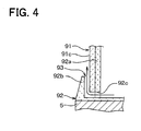
- a ring-shaped guide portion 92b is formed on an outer edge of the flange portion. The guide portion 92b projects from a surface of the flange portion, opposite to the mounting surface, in a direction opposite to a direction in which the SiC single crystal 20 is grown.
- An inner wall surface of the guide portion 92b is perpendicular to the mounting surface and coaxially arranged with the cylindrical tube portion 92a.
- the inner wall surface of the guide portion 92b is located facing an outer wall surface of the second cylindrical tube 91c so that a clearance can be formed between the inner wall surface of the guide portion 92b and the outer wall surface of the second cylindrical tube 91c.
- the clearance between the inner wall surface of the guide portion 92b and the outer wall surface of the second cylindrical tube 91c define the second purge gas inlet 93.
- an outer diameter of the guide portion 92b is reduced in the flow direction of the material gas 3.
- an outer wall surface of the guide portion 92b is tapered so that the outer diameter of the guide portion 92b can be smaller on the downstream side than on the upstream side in the flow direction the material gas 3.
- the outer wall surface of the guide portion 92b is inclined with respect to the mounting surface.
- FIG. 4 is a diagram illustrating an enlarged view of a region R2 in FIG. 3 . As shown in FIGS. 3 and 4 , the outer wall surface of the guide portion 92b is tapered so that the outer diameter of the guide portion 92b can be reduced in the flow direction the material gas 3.
- the tapered outer wall surface of the guide portion 92b reduces or prevents contact between the material gas 3 and the outer wall surface of the guide portion 92b. Thus, it is possible to reduce or prevent adhesion of a polycrystal on the outer wall surface of the guide portion 92b.
- communication holes 92c are formed in the cylindrical tube portion 92a.
- the communication holes 92c are located closer to the bottom of the cylindrical tube portion 92a than a tip of the guide portion 92b.
- the communication holes 92c are arranged at a regular interval in a circumferential direction of the cylindrical tube portion 92a.
- the seed crystal 5 is mounted on the mounting surface, and the SiC single crystal 20 is grown on the surface of the seed crystal 5.
- the purge gas which is introduced from the purge gas introduction mechanism 11, is led to the second purge gas inlet 93 through an inner space of the coupling portion 91, an inner space of the cylindrical tube portion 92a, and the communication holes 92c. Then, the purge gas is discharged toward the outer edge of the base 9 through the second purge gas inlet 93.
- the outer wall surface of the second cylindrical tube 91c and the guide portion 92b serves as a guide portion for determining a discharge direction in which the purge gas is discharged in the heating container 8 through the second purge gas inlet 93.
- the second cylindrical tube 91c and the guide portion 92b are coaxially arranged so that the outer wall surface of the second cylindrical tube 91c can be parallel to the inner wall surface of the guide portion 92b.
- the discharge direction extends along the outer wall surface of the second cylindrical tube 91c so that the purge gas discharged through the second purge gas inlet 93 can flow along the outer wall surface of the second cylindrical tube 91c.
- the second heat insulator 10 surrounds the heating container 8 and the base 9 to lead the remainder of the material gas 3 introduced to the base 9 toward the material gas outlet port 4.
- the second heat insulator 10 is configured so that the remainder of the material gas 3 supplied to the seed crystal 5 can flow to the material gas outlet port 4 through a clearance between the base 9 and the second heat insulator 10.
- the purge gas introduction mechanism 11 is configured to rotate and lift the pipe member 11a. Specifically, a first end of the pipe member 11a is connected to a surface of the base 9, opposite to the mounting surface where the seed crystal 5 is mounted. A second end of the pipe member 11a is connected to the purge gas introduction mechanism 11. Thus, the purge gas introduction mechanism 11 can rotate and lift the pipe member 11a along with the base 9, the seed crystal 5, and the SiC single crystal 20. Thus, the purge gas introduction mechanism 11 can keep a growth face of the SiC single crystal 20 at a temperature suitable for growth of the SiC single crystal 20 by rotating and lifting the pipe member 11a according to the growth of the SiC single crystal 20.
- the pipe member 11a can be made of graphite.
- a surface of the pipe member 11a can be coated with a refractory metal carbide such as tantalum carbide (TaC) or niobium carbide (NbC) to reduce or prevent thermal etching of the pipe member 11a.
- a refractory metal carbide such as tantalum carbide (TaC) or niobium carbide (NbC) to reduce or prevent thermal etching of the pipe member 11a.
- the purge gas introduction mechanism 11 introduces the purge gas into the pipe member 11a to supply the purge gas to the base 9 from the back side of the base 9.
- the purge gas can be an inert gas (e.g., Ar, He), an etching gas (e.g., H 2 , HC1), or a mixture gas of the inert gas and the etching gas.
- the purge gas that is supplied from the purge gas introduction mechanism 11 to the base 9 is discharged toward the outer edge of the base 9.
- Each of the first heating device 12 and the second heating device 13 surrounds the vacuum container 6.
- each of the first heating device 12 and the second heating device 13 can include a heat-generating induction coil, a heater, or the like.
- the first heating device 12 is located at a position corresponding to a lower part of the heating container 8, and the second heating device 13 is located at a position corresponding to the base 9.
- the first heating device 12 and the second heating device 13 are independently controlled so that the growth face of the SiC single crystal 20 can be adjusted to the temperature suitable for the growth of the SiC single crystal 20.
- the seed crystal 5 is mounted on the base 9. Then, the first heating device 12 and the second heating device 13 are controlled to generate a predetermined temperature distribution in the heating container 8.
- the predetermined temperature distribution is set so that the material gas 3 can be recrystallized at a surface of the seed crystal 5 to grow the SiC single crystal 20. Further, the predetermined temperature distribution is set so that the recrystallization rate can be less than a sublimation rate in the heating container 8.
- the vacuum container 6 is kept at a predetermined pressure, and the material gas 3 is introduced into the vacuum container 6 through the gas introduction pipe 7a.
- a carrier gas e.g., inert gas such as Ar, He
- an etching gas e.g., H 2 , HC1
- the material gas 3 is supplied to the seed crystal 5 so that the SiC single crystal 20 can be grown on the seed crystal 5.
- the purge gas introduction mechanism 11 and the purge gas source 14 introduces the purge gas through the pipe member 11a and the first purge gas inlet 8b.
- the purge gas is supplied from the pipe member 11a to the outer edge of the base 9 through a purge gas introduction path of the base 9.
- the purge gas supplied from the pipe member 11a is discharged from the base 9 through the second purge gas inlet 93 in the same direction as the flow direction of the material gas 3 so that the purge gas discharged through the second purge gas inlet 93 can flow along the outer wall surface of the base 9 (i.e., the second cylindrical tube 91c).
- the purge gas introduced from the purge gas source 14 is discharged through the first purge gas inlet 8b of the heating container 8 in the same direction as the flow direction of the material gas 3 so that the purge gas discharged through the first purge gas inlet 8b can flow along the inner wall surface of the heating container 8 (i.e., the first cylindrical tube 8c) to surround the base 9.
- Such a flow of the purge gas reduces or prevents formation of a polycrystal on a portion around the base 9 and on the inner surface of the heating container 8.
- the formation of the polycrystal on a portion around the seed crystal 5 is reduced or prevented, and clogging of a flow path of the material gas 3 due to the formation of the polycrystal can be avoided. Therefore, it is possible to grow the SiC single crystal 20 for a long time.
- the inner wall surface of the first cylindrical tube 8c is parallel to the outer wall surface of the second cylindrical tube 8d
- the outer wall surface of the second cylindrical tube 91c is parallel to the inner wall surface of the guide portion 92b.
- the purge gas discharged though the first purge gas inlet 8b can accurately flow along the inner wall surface of the first cylindrical tube 8c
- the purge gas discharged though the second purge gas inlet 93 can accurately flow along the outer wall surface of the second cylindrical tube 91c.
- the formation of the polycrystal on the portion around the base 9 and on the inner surface of the heating container 8 can be effectively reduced or prevented.
- the purge gas flows to the inner wall surface of the heating container 8 and the outer edge of the base 9.
- Such a flow of the purge gas reduces or prevents the formation of the polycrystal on the portion around the base 9 and on the inner wall surface of the heating container 8.
- clogging of the flow path of the material gas 3 due to the formation of the polycrystal can be avoided. Therefore, it is possible to grow the SiC single crystal 20 for a long time.
- the flow of the purge gas reduces or prevents the formation of the polycrystal on the portion around the seed crystal 5. Therefore, even when the SiC single crystal 20 is grown long, it is possible to reduce or prevent adhesion of the polycrystal to the outer edge of the SiC single crystal 20. Therefore, the SiC single crystal 20 can be grown long without loss of quality of the outer edge of the SiC single crystal 20.
- a second embodiment of the present invention is described below with reference to FIGS. 5-7 .
- the second embodiment differs from the first embodiment in the shapes of the heating container 8 and the base 9.
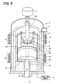
- FIG. 5 is a diagram illustrating a perspective cross-sectional view of a SiC single crystal manufacturing apparatus 1 according to the second embodiment of the present invention.
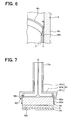
- FIG. 6 is a diagram illustrating an enlarged view of a region R3 in FIG. 5 , showing the heating container 8.
- FIG. 7 is a diagram illustrating a partial enlarged view of FIG. 5 , showing the base 9.
- the heating container 8 is discussed.
- the open end of the second cylindrical tube 8d of the heating container 8 is tapered so that the inner wall surface of the second cylindrical tube 8d can form a predetermined angle ⁇ with the outer wall surface of the second cylindrical tube 8d.
- the inner wall surface of the open end of the second cylindrical tube 8d is tapered (i.e., inclined) to form the angle ⁇ with the outer wall surface of the second cylindrical tube 8d so that the inner diameter of the second cylindrical tube 8d can be increased in the flow direction the material gas 3.
- the angle ⁇ is not limited to a specific value. Nevertheless, it is preferable that the angle ⁇ be 45 degrees or less.
- the inner diameter of the open end of the second cylindrical tube 8d is gradually increased, it is less likely that the material gas 3 comes into contact with the inner wall surface of the heating container 8 on the upstream side of the first purge gas inlet 8b in the flow direction of the material gas 3.
- the angle ⁇ which is formed by the tapered inner surface of the second cylindrical tube 8d and the outer wall surface of the second cylindrical tube 8d, is 45 degrees or less, it is less likely that the flow of the material gas 3 affects the flow of the purge gas. Therefore, as shown in FIG. 6 , the purge gas and the material gas 3 can flow smoothly without interfering with each other.
- the base 9 As shown in FIG. 7 , according to the second embodiment, like the first embodiment, the base 9 includes the coupling portion 91 and the mounting portion 92. However, the coupling portion 91 and the mounting portion 92 of the second embodiment differ in shape from those of the first embodiment.
- the coupling portion 91 includes the first cylindrical tube 91a, the flange 91b, and the second cylindrical tube 91c.
- the second cylindrical tube 91c has a stepped portion. That is, the second cylindrical tube 91c has a thicker portion and a thinner portion. The thicker portion is located closer to the flange 91b than the thinner portion. An inner diameter of the thicker portion is less than an inner diameter of the thinner portion. That is, the second cylindrical tube 91c has two different inner diameters.
- the thinner portion of the second cylindrical tube 91c serves as a ring-shaped guide portion.
- the mounting portion 92 includes the cylindrical tube portion 92a with a thick bottom 92d.
- a tube part of the cylindrical tube portion 92a extends from the bottom 92d in its axis direction, and the communication holes 92c are formed in the tube portion 92a.
- the outer diameter of the mounting portion 92 is constant.
- the tube part of the mounting portion 92 is fitted into the thicker portion of the second cylindrical tube 91c.
- An adhesive is applied between the tube part of the mounting portion 92 and the thicker portion of the second cylindrical tube 91c so that the coupling portion 91 and the mounting portion 92 can be fixed together.
- the communication holes 92c is spaced from and surrounded by the thinner portion of the second cylindrical tube 91c without being blocked with the thick portion of the second cylindrical tube 91c.
- a clearance between the thinner portion of the second cylindrical tube 91c and the tube part of the mounting portion 92 serves as the second purge gas inlet 93.
- the purge gas is supplied from the pipe member 11a to the outer edge of the base 9 through the purge gas introduction path of the base 9. Then, the supplied purge gas is discharged from the base 9 through the second purge gas inlet 93 in the opposite direction to the flow direction of the material gas 3 so that the discharged purge gas can flow along the outer wall surface of the base 9 (i.e., the cylindrical tube portion 92a).
- the open end of the second cylindrical tube 8d is tapered. In such an approach, it is less likely that the material gas 3 comes into contact with the inner wall surface of the heating container 8 on the upstream side of the first purge gas inlet 8b in the flow direction of the material gas 3. Thus, it is possible to reduce or prevent adhesion of the polycrystal to the inner wall surface of the heating container 8.
- the purge gas supplied to the outer edge of the base 9 is discharged through the second purge gas inlet 93 in the opposite direction to the flow direction of the material gas 3. Even in such an approach, the same effect as the first embodiments can be obtained.
- a third embodiment of the present invention is described below with reference to FIGS. 8 and 9 .
- the third embodiment differs from the first embodiment in the following points.
- FIG. 8 is a diagram illustrating a perspective cross-sectional view of a base 9 of a SiC single crystal manufacturing apparatus 1 according to the third embodiment
- FIG. 9 is a diagram illustrating a cross-sectional view of the base 9 of FIG. 8 . It is noted that FIG. 8 illustrates a bottom side view of the SiC single crystal manufacturing apparatus 1.
- the base 9 includes the coupling portion 91 and the mounting portion 92.
- the coupling portion 91 and the mounting portion 92 of the third embodiment differ in shape from those of the first embodiment.
- the coupling portion 91 has a hollow disc shape.
- An inner space of the coupling portion 91 has two different diameters. That is, the coupling portion 91 has a thicker portion and a thinner portion. An inner diameter of the thicker portion is less than an inner diameter of the thinner portion.
- the mounting portion 92 is partially inserted into the thinner portion of the coupling portion 91.
- An outer wall surface of the thinner portion of the coupling portion 91 is tapered.
- the mounting portion 92 includes a circular plate 92e and a solid cylinder 92f.
- the plate 92e has a first surface and a second surface opposite to the first surface.
- the first surface of the plate 92e defines the mounting surface where the seed crystal 5 is mounted.
- the cylinder 92f is located on the second surface of the plate 92e.
- a lower surface of the coupling portion 91 is parallel to and spaced from the second surface of the plate 92e by a predetermined constant distance (e.g., 5mm or less).
- a clearance between the lower surface of the coupling portion 91 and the second surface of the plate 92e serves as the second purge gas inlet 93.
- the plate 92e serves as a guide portion for causing the second purge gas inlet 93 to face in the radial outward direction of the base 9.
- the coupling portion 91 and the mounting portion 92 are fixed together, for example, by projections that are formed on the inner surface of the coupling portion 91 or on the outer surface of the cylinder 92f of the mounting portion 92.
- the purge gas flows to the second purge gas inlet 93 through between the projections.
- the second purge gas inlet 93 faces in the radial outward direction so that the purge gas can be discharged from the outer edge of the seed crystal 5 in the radial outward direction. Since the purge gas is discharged from near the mounting surface where the seed crystal 5 is mounted, it is possible to prevent or reduce adhesion of the polycrystal on the near side of the base 9 from the seed crystal 5.
- the outer wall surface of the coupling portion 91 is tapered. In such an approach, the material gas 3 and the discharged purge gas can smoothly flow along the outer wall surface of the coupling portion 91.
- a fourth embodiment of the present invention is described below with reference to FIGS. 10 and 11 .
- the fourth embodiment differs from the first embodiment in the shapes of the heating container 8 and the base 9.
- FIG. 10 is a diagram illustrating a perspective cross-sectional view of a SiC single crystal manufacturing apparatus 1 according to the fourth embodiment.
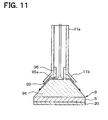
- FIG. 11 is a diagram illustrating a partial enlarged view of FIG. 10 , showing the base 9.
- the heating container 8 is discussed. As shown in FIG. 10 , according to the fourth embodiment, the inner wall surface of the heating container 8 is tapered so that the inner diameter of the heating container 8 can be reduced in the flow direction the material gas 3. Specifically, the inner diameter of the first cylindrical tube 8c is gradually reduced on the downstream side of the first purge gas inlet 8b in the flow direction of the material gas 3. More specifically, the first cylindrical tube 8c has a first tube part and a second tube part communicating with the first part. An inner diameter of the first tube part of the first cylindrical tube 8c is gradually reduced in the flow direction of the material gas 3. The first tube part of the first cylindrical tube 8c is located on the downstream side of the second tube part of the first cylindrical tube 8c in the flow direction of the material gas 3. Further, the first tube part of the first cylindrical tube 8c is located on the downstream side of the first purge gas inlet 8b in the flow direction of the material gas 3.
- the base 9 includes a frustum 94 and a cylindrical tube 95.
- the frustum 94 has a top surface and a bottom surface larger in area than the top surface.
- the seed crystal 5 is mounted on the bottom surface of the frustum 94. That is, the bottom surface of the frustum 94 defines the mounting surface.
- the tube 95 extends perpendicularly from the top surface of the frustum 94.
- the tube 95 is inserted into an end portion of the pipe member 11a so that the tube 95 and the pipe member 11a can communicate with each other.
- Communication holes 95a are formed in the tube 95 and arranged at a regular interval in a circumferential direction of the tube 95.
- the purge gas introduced through the pipe member 11a is discharged through the communication holes 95a.
- the end portion of the pipe member 11a spreads toward the end to form a ring-shaped guide portion 11b.
- the guide portion 11b extends parallel to an outer wall surface (side wall surface) of the frustum 94.
- the outer wall surface of the frustum 94 is parallel to and spaced from an inner wall surface of the guide portion 11b.
- a clearance between the outer wall surface of the frustum 94 and the inner wall surface of the guide portion 11b serves as the second purge gas inlet 93.
- the purge gas that is discharged through the first purge gas inlet 8b of the heating container 8 flows along the inner wall surface of the heating container 8 in the same direction as the flow direction of the material gas 3. Further, the purge gas that is discharged through the second purge gas inlet 93 of the base 9 flows along the outer wall surface of the base 9 in the opposite direction to the flow direction of the material gas 3.
- the inner diameter of the heating container 8 is reduced in the flow direction of the purge gas that is discharged through the first purge gas inlet 8b, and the outer diameter of the base 9 is increased in the flow direction of the purge gas that is discharged through the second purge gas inlet 93.
- the purge gas effectively flows along the inner wall surface of the heating container 8 and the outer wall surface of the base 9 so that the formation of the polycrystal can be effectively reduced or prevented.
- the surfaces of the heating container 8 and the base 9 be coated with a refractory metal carbide such as tantalum carbide (TaC) or niobium carbide (NbC) to reduce or prevent thermal etching of the heating container 8 and the base 9.
- a refractory metal carbide such as tantalum carbide (TaC) or niobium carbide (NbC)
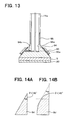
- a fifth embodiment of the present invention is described below with reference to FIGS. 12 and 13 .
- the fifth embodiment differs from the first embodiment in the shape of the base 9.
- FIG. 12 is a diagram illustrating a perspective cross-sectional view of a SiC single crystal manufacturing apparatus 1 according to the fifth embodiment.
- FIG. 13 is a diagram illustrating a partial enlarged view of FIG. 12 , showing the base 9.
- the base 9 includes a frustum 94, a cylindrical tube 95, and a guide portion 96.
- the frustum 94 has a top surface and a bottom surface larger in area than the top surface.
- the seed crystal 5 is mounted on the bottom surface of the frustum 94. That is, the bottom surface of the frustum 94 defines the mounting surface.
- the tube 95 extends perpendicularly from the top surface of the frustum 94.
- the tube 95 is engaged with an end portion of the pipe member 11a so that the tube 95 and the pipe member 11a can communicate with each other.
- the guide portion 96 is located around the frustum 94.
- the top surface of the frustum 94 is recessed to form a recess 94a.
- the recess 94a communicates with the pipe member 11a.
- communication holes 94b are formed in an inner wall surface of the recess 94a.
- the communication holes 94b are located closer to a bottom of the recess 94a than an opening of the recess 94a.
- the communication holes 94b are arranged at a regular interval in a circumferential direction of the recess 94a.
- the purge gas introduced through the pipe member 11a is discharged through the communication holes 94b.
- the guide portion 96 has a hollow frustum shape spreading toward the end. Specifically, the guide portion 96 extends parallel to an outer wall surface (side wall surface) of the frustum 94. Multiple supporting potions 96a project from an inner wall surface of the guide portion 96 and support the guide portion 96 on the outer wall surface of the frustum 94. Each supporting portion 96a has a predetermined length. Thus, the outer wall surface of the frustum 94 is parallel to and spaced from the inner wall surface of the guide portion 96. A clearance between the outer wall surface of the frustum 94 and the inner wall surface of the guide portion 96 serves as the second purge gas inlet 93.
- the guide portion 96 covers the communication holes 94b of the frustum 94 so that the purge gas discharged through the communication holes 94b can flow not only in the same direction as the flow direction of the material gas 3 but also in the opposite direction to the flow direction of the material gas 3.
- the base 9 has the guide portion 96 for causing the second purge gas inlet 93 to face not only toward the seed crystal 5 but also toward the pipe member 11a.
- the purge gas can be discharged not only in the same direction as the flow direction of the material gas 3 but also in the opposite direction to the flow direction of the material gas 3.
- the first purge gas inlet 8b extends circularly along the inner wall surface of the heating container 8 in a circumferential direction of the heating container 8. That is, the first purge gas inlet 8b has a closed circle shape along the entire inner circumferential surface of the heating container 8. In such an approach, the flow of the purge gas around the base 9 becomes uniform so that the formation of the polycrystal can be effectively reduced or prevented.
- the shape of the first purge gas inlet 8b is not limited to such a closed circle along the inner wall surface of the heating container 8.
- the heating container 8 can be a circular tube having a thicker portion defining a first diameter and a thinner portion defining a second diameter larger than the first diameter.
- the thinner portion is located on the downstream side of the thicker portion in the flow direction of the material gas 3.
- a ring-shape guide portion having a third inner diameter less than the first diameter is placed at an interface between the thicker portion and the thinner portion to from a clearance, as the first purge gas inlet 8b, between the guide portion and the thinner portion.
- communication holes are formed in a bottom of the clearance and arranged in a regular interval in the circumferential direction of the heating container 8.
- the open end of the second cylindrical tube 8d is tapered so that the inner diameter of the second cylindrical tube 8d can be increased in the flow direction of the material gas 3.
- Such a structure as discussed in the second embodiment can be applied to the first, third, fourth, and fifth embodiments.
- the open end of the second cylindrical tube 8d can have a shape other a tapered shape, as long as the inner diameter of the open end of the second cylindrical tube 8d can be increased in the flow direction of the material gas 3.
- the open end of the second cylindrical tube 8d can have a triangle shape, a large-diameter shape, an ellipsoidal shape, or a sectorial shape.
- the angle ⁇ can be defined as an angle between a tangent line to the rounded inner wall surface of the open end of the second cylindrical tube 8d and the outer wall surface of the second cylindrical tube 8d.
- the second purge gas inlet 93 of the base 9 allows the purge gas to be discharged in two directions.
- the purge gas can be discharged in more than two directions.
- three or more second purge gas inlets 93 can be provided to the base 9.
- the second purge gas inlet 93 of the first embodiment and the second purge gas inlet 93 of the fifth embodiment can be combined so that the purge gas can be discharged in three directions.
- the purge gas is discharged through the first purge gas inlet 8b on the inner wall surface of the heating container 8 in the same direction as the flow direction of the material gas 3.
- the first purge gas inlet 8b is pointed downward so that the purge gas can be discharged through the first purge gas inlet 8b in the opposite direction to the flow direction of the material gas 3.
- the heating container 8 can be provided with multiple first purge gas inlets 8b.
Landscapes
- Chemical & Material Sciences (AREA)
- Engineering & Computer Science (AREA)
- Crystallography & Structural Chemistry (AREA)
- Materials Engineering (AREA)
- Metallurgy (AREA)
- Organic Chemistry (AREA)
- Chemical Kinetics & Catalysis (AREA)
- General Chemical & Material Sciences (AREA)
- Inorganic Chemistry (AREA)
- Crystals, And After-Treatments Of Crystals (AREA)
Applications Claiming Priority (1)
| Application Number | Priority Date | Filing Date | Title |
|---|---|---|---|
| JP2010280308A JP5212455B2 (ja) | 2010-12-16 | 2010-12-16 | 炭化珪素単結晶の製造装置 |
Publications (3)
| Publication Number | Publication Date |
|---|---|
| EP2465979A2 true EP2465979A2 (de) | 2012-06-20 |
| EP2465979A3 EP2465979A3 (de) | 2013-11-20 |
| EP2465979B1 EP2465979B1 (de) | 2019-01-30 |
Family
ID=45318954
Family Applications (1)
| Application Number | Title | Priority Date | Filing Date |
|---|---|---|---|
| EP11192939.4A Active EP2465979B1 (de) | 2010-12-16 | 2011-12-12 | Verfahren zur Herstellung eines Siliziumcarbid-Einkristalls |
Country Status (5)
| Country | Link |
|---|---|
| US (1) | US8882911B2 (de) |
| EP (1) | EP2465979B1 (de) |
| JP (1) | JP5212455B2 (de) |
| KR (1) | KR101447476B1 (de) |
| CN (2) | CN107254715A (de) |
Cited By (1)
| Publication number | Priority date | Publication date | Assignee | Title |
|---|---|---|---|---|
| EP4279641A1 (de) * | 2022-05-18 | 2023-11-22 | Zadient Technologies SAS | Verbesserte ofenvorrichtung für die kristallproduktion mit kornhalter-repositioniereinheit |
Families Citing this family (15)
| Publication number | Priority date | Publication date | Assignee | Title |
|---|---|---|---|---|
| JP5287840B2 (ja) * | 2010-12-16 | 2013-09-11 | 株式会社デンソー | 炭化珪素単結晶の製造装置 |
| FR3002241B1 (fr) * | 2013-02-21 | 2015-11-20 | Altatech Semiconductor | Dispositif de depot chimique en phase vapeur |
| KR102106969B1 (ko) * | 2013-02-26 | 2020-05-08 | 삼성디스플레이 주식회사 | 기판 열처리 장치 및 그 방법 |
| US10633762B2 (en) | 2013-09-06 | 2020-04-28 | GTAT Corporation. | Method for producing bulk silicon carbide by sublimation of a silicon carbide precursor prepared from silicon and carbon particles or particulate silicon carbide |
| JP6187372B2 (ja) * | 2014-04-11 | 2017-08-30 | 株式会社デンソー | 炭化珪素単結晶製造装置 |
| EP3450595B1 (de) | 2016-04-28 | 2021-07-14 | Kwansei Gakuin Educational Foundation | Epitaktisches wachstumsverfahren in der dampfphase und verfahren zur herstellung eines substrats mit der epitaxialschicht |
| CN107794565B (zh) * | 2016-09-06 | 2020-11-13 | 上海新昇半导体科技有限公司 | 籽晶夹头及直拉单晶炉 |
| JP7242987B2 (ja) | 2018-09-06 | 2023-03-22 | 株式会社レゾナック | SiC単結晶製造装置 |
| CN111501095B (zh) * | 2020-05-19 | 2021-03-05 | 青岛佳恩半导体有限公司 | 一种碳化硅单晶体生长装置及其方法 |
| CN112374766B (zh) * | 2020-11-13 | 2022-10-18 | 重庆理工大学 | 一种用于小尺寸圆管内壁薄膜沉积的装置 |
| JP7790022B2 (ja) * | 2020-11-27 | 2025-12-23 | 株式会社レゾナック | 種結晶保持部材及びそれを備えた単結晶製造装置 |
| JP2022085346A (ja) * | 2020-11-27 | 2022-06-08 | 昭和電工株式会社 | SiC単結晶の製造方法 |
| JP7639335B2 (ja) * | 2020-12-28 | 2025-03-05 | 株式会社レゾナック | 炭化珪素単結晶製造装置および炭化珪素単結晶の製造方法 |
| CN113249783A (zh) * | 2021-05-12 | 2021-08-13 | 中科汇通(内蒙古)投资控股有限公司 | 一种可供多个碳化硅单晶同时生长的装置 |
| CN115012038A (zh) * | 2022-05-31 | 2022-09-06 | 眉山博雅新材料股份有限公司 | 一种籽晶支撑装置 |
Citations (2)
| Publication number | Priority date | Publication date | Assignee | Title |
|---|---|---|---|---|
| US5704985A (en) | 1995-06-26 | 1998-01-06 | Abb Research Ltd. | Device and a method for epitaxially growing objects by CVD |
| US20080022923A1 (en) | 2006-07-28 | 2008-01-31 | Caracal, Inc. | Seed holder for crystal growth reactors |
Family Cites Families (18)
| Publication number | Priority date | Publication date | Assignee | Title |
|---|---|---|---|---|
| JP3419144B2 (ja) | 1995-04-21 | 2003-06-23 | 株式会社豊田中央研究所 | 単結晶成長装置 |
| DE19603323A1 (de) | 1996-01-30 | 1997-08-07 | Siemens Ag | Verfahren und Vorrichtung zum Herstellen von SiC durch CVD mit verbesserter Gasausnutzung |
| SE9603586D0 (sv) * | 1996-10-01 | 1996-10-01 | Abb Research Ltd | A device for epitaxially growing objects and method for such a growth |
| US6063186A (en) * | 1997-12-17 | 2000-05-16 | Cree, Inc. | Growth of very uniform silicon carbide epitaxial layers |
| JPH11268990A (ja) | 1998-03-20 | 1999-10-05 | Denso Corp | 単結晶の製造方法および製造装置 |
| JP3959952B2 (ja) | 2000-11-10 | 2007-08-15 | 株式会社デンソー | 炭化珪素単結晶の製造方法及び製造装置 |
| CN1367275A (zh) * | 2001-01-20 | 2002-09-04 | 上海德波赛康科研有限公司 | 块状碳化硅单晶生长的制备方法 |
| JP4742448B2 (ja) * | 2001-06-06 | 2011-08-10 | 株式会社デンソー | 炭化珪素単結晶の製造方法及び製造装置 |
| JP4329282B2 (ja) | 2001-06-22 | 2009-09-09 | 株式会社デンソー | 炭化珪素単結晶の製造方法 |
| JP3922074B2 (ja) | 2002-04-09 | 2007-05-30 | 株式会社デンソー | 炭化珪素単結晶の製造方法および製造装置 |
| DE602004001802T3 (de) * | 2003-04-24 | 2012-01-26 | Norstel Ab | Vorrichtung und Verfahren zur Herstellung von Einkristallen durch Dampfphasenabscheidung |
| ITMI20031196A1 (it) * | 2003-06-13 | 2004-12-14 | Lpe Spa | Sistema per crescere cristalli di carburo di silicio |
| JP4706565B2 (ja) * | 2006-06-08 | 2011-06-22 | 株式会社デンソー | 炭化珪素単結晶の製造方法 |
| JP4962074B2 (ja) * | 2007-03-22 | 2012-06-27 | 株式会社デンソー | 炭化珪素単結晶の製造装置および製造方法 |
| JP4535116B2 (ja) * | 2007-10-31 | 2010-09-01 | 株式会社デンソー | 炭化珪素単結晶の製造装置および製造方法 |
| JP4591523B2 (ja) * | 2008-03-05 | 2010-12-01 | 株式会社デンソー | 炭化珪素単結晶の製造装置 |
| JP4941475B2 (ja) * | 2009-01-26 | 2012-05-30 | 株式会社デンソー | 炭化珪素単結晶の製造方法およびそれに適した製造装置 |
| JP5332916B2 (ja) * | 2009-06-03 | 2013-11-06 | 株式会社デンソー | 炭化珪素単結晶の製造装置 |
-
2010
- 2010-12-16 JP JP2010280308A patent/JP5212455B2/ja active Active
-
2011
- 2011-12-12 EP EP11192939.4A patent/EP2465979B1/de active Active
- 2011-12-14 US US13/325,259 patent/US8882911B2/en active Active
- 2011-12-14 KR KR1020110134714A patent/KR101447476B1/ko active Active
- 2011-12-16 CN CN201710281775.4A patent/CN107254715A/zh active Pending
- 2011-12-16 CN CN2011104317623A patent/CN102534770A/zh active Pending
Patent Citations (3)
| Publication number | Priority date | Publication date | Assignee | Title |
|---|---|---|---|---|
| US5704985A (en) | 1995-06-26 | 1998-01-06 | Abb Research Ltd. | Device and a method for epitaxially growing objects by CVD |
| JPH11508531A (ja) | 1995-06-26 | 1999-07-27 | エービービー リサーチ リミテッド | Cvdによって目的物をエピタキシアル成長させる装置と方法 |
| US20080022923A1 (en) | 2006-07-28 | 2008-01-31 | Caracal, Inc. | Seed holder for crystal growth reactors |
Cited By (2)
| Publication number | Priority date | Publication date | Assignee | Title |
|---|---|---|---|---|
| EP4279641A1 (de) * | 2022-05-18 | 2023-11-22 | Zadient Technologies SAS | Verbesserte ofenvorrichtung für die kristallproduktion mit kornhalter-repositioniereinheit |
| WO2023222790A1 (en) * | 2022-05-18 | 2023-11-23 | Zadient Technologies SAS | Improved furnace apparatus for crystal production with seed holder repositioning unit |
Also Published As
| Publication number | Publication date |
|---|---|
| CN107254715A (zh) | 2017-10-17 |
| JP2012126612A (ja) | 2012-07-05 |
| US8882911B2 (en) | 2014-11-11 |
| CN102534770A (zh) | 2012-07-04 |
| JP5212455B2 (ja) | 2013-06-19 |
| EP2465979B1 (de) | 2019-01-30 |
| US20120152166A1 (en) | 2012-06-21 |
| KR20120067944A (ko) | 2012-06-26 |
| EP2465979A3 (de) | 2013-11-20 |
| KR101447476B1 (ko) | 2014-10-06 |
Similar Documents
| Publication | Publication Date | Title |
|---|---|---|
| EP2465979B1 (de) | Verfahren zur Herstellung eines Siliziumcarbid-Einkristalls | |
| KR101139132B1 (ko) | 기상 성장 장치용 서셉터 | |
| US8568531B2 (en) | Seed holder for crystal growth reactors | |
| EP0865518B1 (de) | Vorrichtung zum wärmebehandeln von objekten | |
| US20110155048A1 (en) | Manufacturing apparatus and manufacturing method of silicon carbide single crystal | |
| EP2465980B1 (de) | Vorrichtung und Verfahren zur Herstellung eines Siliciumcarbid-Einkristalls | |
| US11326275B2 (en) | SiC epitaxial growth apparatus having purge gas supply ports which surround a vicinity of a raw material gas supply port | |
| TW201920762A (zh) | 氣相成長裝置以及氣相成長方法 | |
| JP5556761B2 (ja) | 炭化珪素単結晶製造装置 | |
| WO2021225047A1 (ja) | 成膜装置およびプレート | |
| US20210040645A1 (en) | Silicon carbide single crystal manufacturing apparatus, and manufacturing method of silicon carbide single crystal | |
| US20210217648A1 (en) | Susceptor and chemical vapor deposition apparatus | |
| JP2015198213A (ja) | エピタキシャル炭化珪素ウェハの製造方法及びそれに用いる炭化珪素単結晶基板のホルダー | |
| JP5648604B2 (ja) | 炭化珪素単結晶製造装置 | |
| JP6052051B2 (ja) | 炭化珪素単結晶の製造装置 | |
| US20260015764A1 (en) | Semiconductor crystal manufacturing apparatus | |
| JP5578146B2 (ja) | 炭化珪素単結晶製造装置 |
Legal Events
| Date | Code | Title | Description |
|---|---|---|---|
| PUAI | Public reference made under article 153(3) epc to a published international application that has entered the european phase |
Free format text: ORIGINAL CODE: 0009012 |
|
| AK | Designated contracting states |
Kind code of ref document: A2 Designated state(s): AL AT BE BG CH CY CZ DE DK EE ES FI FR GB GR HR HU IE IS IT LI LT LU LV MC MK MT NL NO PL PT RO RS SE SI SK SM TR |
|
| AX | Request for extension of the european patent |
Extension state: BA ME |
|
| PUAL | Search report despatched |
Free format text: ORIGINAL CODE: 0009013 |
|
| AK | Designated contracting states |
Kind code of ref document: A3 Designated state(s): AL AT BE BG CH CY CZ DE DK EE ES FI FR GB GR HR HU IE IS IT LI LT LU LV MC MK MT NL NO PL PT RO RS SE SI SK SM TR |
|
| AX | Request for extension of the european patent |
Extension state: BA ME |
|
| RIC1 | Information provided on ipc code assigned before grant |
Ipc: C30B 25/14 20060101AFI20131014BHEP Ipc: C30B 29/36 20060101ALI20131014BHEP Ipc: C30B 25/16 20060101ALI20131014BHEP |
|
| 17P | Request for examination filed |
Effective date: 20140403 |
|
| RBV | Designated contracting states (corrected) |
Designated state(s): AL AT BE BG CH CY CZ DE DK EE ES FI FR GB GR HR HU IE IS IT LI LT LU LV MC MK MT NL NO PL PT RO RS SE SI SK SM TR |
|
| 17Q | First examination report despatched |
Effective date: 20160503 |
|
| GRAP | Despatch of communication of intention to grant a patent |
Free format text: ORIGINAL CODE: EPIDOSNIGR1 |
|
| STAA | Information on the status of an ep patent application or granted ep patent |
Free format text: STATUS: GRANT OF PATENT IS INTENDED |
|
| INTG | Intention to grant announced |
Effective date: 20180705 |
|
| GRAS | Grant fee paid |
Free format text: ORIGINAL CODE: EPIDOSNIGR3 |
|
| GRAA | (expected) grant |
Free format text: ORIGINAL CODE: 0009210 |
|
| STAA | Information on the status of an ep patent application or granted ep patent |
Free format text: STATUS: THE PATENT HAS BEEN GRANTED |
|
| AK | Designated contracting states |
Kind code of ref document: B1 Designated state(s): AL AT BE BG CH CY CZ DE DK EE ES FI FR GB GR HR HU IE IS IT LI LT LU LV MC MK MT NL NO PL PT RO RS SE SI SK SM TR |
|
| REG | Reference to a national code |
Ref country code: GB Ref legal event code: FG4D |
|
| REG | Reference to a national code |
Ref country code: CH Ref legal event code: EP |
|
| REG | Reference to a national code |
Ref country code: AT Ref legal event code: REF Ref document number: 1093338 Country of ref document: AT Kind code of ref document: T Effective date: 20190215 |
|
| REG | Reference to a national code |
Ref country code: IE Ref legal event code: FG4D |
|
| REG | Reference to a national code |
Ref country code: DE Ref legal event code: R096 Ref document number: 602011056066 Country of ref document: DE |
|
| REG | Reference to a national code |
Ref country code: SE Ref legal event code: TRGR |
|
| REG | Reference to a national code |
Ref country code: LT Ref legal event code: MG4D |
|
| REG | Reference to a national code |
Ref country code: NL Ref legal event code: MP Effective date: 20190130 |
|
| PG25 | Lapsed in a contracting state [announced via postgrant information from national office to epo] |
Ref country code: NL Free format text: LAPSE BECAUSE OF FAILURE TO SUBMIT A TRANSLATION OF THE DESCRIPTION OR TO PAY THE FEE WITHIN THE PRESCRIBED TIME-LIMIT Effective date: 20190130 Ref country code: PT Free format text: LAPSE BECAUSE OF FAILURE TO SUBMIT A TRANSLATION OF THE DESCRIPTION OR TO PAY THE FEE WITHIN THE PRESCRIBED TIME-LIMIT Effective date: 20190530 Ref country code: LT Free format text: LAPSE BECAUSE OF FAILURE TO SUBMIT A TRANSLATION OF THE DESCRIPTION OR TO PAY THE FEE WITHIN THE PRESCRIBED TIME-LIMIT Effective date: 20190130 Ref country code: PL Free format text: LAPSE BECAUSE OF FAILURE TO SUBMIT A TRANSLATION OF THE DESCRIPTION OR TO PAY THE FEE WITHIN THE PRESCRIBED TIME-LIMIT Effective date: 20190130 Ref country code: ES Free format text: LAPSE BECAUSE OF FAILURE TO SUBMIT A TRANSLATION OF THE DESCRIPTION OR TO PAY THE FEE WITHIN THE PRESCRIBED TIME-LIMIT Effective date: 20190130 Ref country code: NO Free format text: LAPSE BECAUSE OF FAILURE TO SUBMIT A TRANSLATION OF THE DESCRIPTION OR TO PAY THE FEE WITHIN THE PRESCRIBED TIME-LIMIT Effective date: 20190430 Ref country code: FI Free format text: LAPSE BECAUSE OF FAILURE TO SUBMIT A TRANSLATION OF THE DESCRIPTION OR TO PAY THE FEE WITHIN THE PRESCRIBED TIME-LIMIT Effective date: 20190130 |
|
| REG | Reference to a national code |
Ref country code: DE Ref legal event code: R084 Ref document number: 602011056066 Country of ref document: DE |
|
| REG | Reference to a national code |
Ref country code: AT Ref legal event code: MK05 Ref document number: 1093338 Country of ref document: AT Kind code of ref document: T Effective date: 20190130 |
|
| PG25 | Lapsed in a contracting state [announced via postgrant information from national office to epo] |
Ref country code: IS Free format text: LAPSE BECAUSE OF FAILURE TO SUBMIT A TRANSLATION OF THE DESCRIPTION OR TO PAY THE FEE WITHIN THE PRESCRIBED TIME-LIMIT Effective date: 20190530 Ref country code: BG Free format text: LAPSE BECAUSE OF FAILURE TO SUBMIT A TRANSLATION OF THE DESCRIPTION OR TO PAY THE FEE WITHIN THE PRESCRIBED TIME-LIMIT Effective date: 20190430 Ref country code: RS Free format text: LAPSE BECAUSE OF FAILURE TO SUBMIT A TRANSLATION OF THE DESCRIPTION OR TO PAY THE FEE WITHIN THE PRESCRIBED TIME-LIMIT Effective date: 20190130 Ref country code: HR Free format text: LAPSE BECAUSE OF FAILURE TO SUBMIT A TRANSLATION OF THE DESCRIPTION OR TO PAY THE FEE WITHIN THE PRESCRIBED TIME-LIMIT Effective date: 20190130 Ref country code: LV Free format text: LAPSE BECAUSE OF FAILURE TO SUBMIT A TRANSLATION OF THE DESCRIPTION OR TO PAY THE FEE WITHIN THE PRESCRIBED TIME-LIMIT Effective date: 20190130 Ref country code: GR Free format text: LAPSE BECAUSE OF FAILURE TO SUBMIT A TRANSLATION OF THE DESCRIPTION OR TO PAY THE FEE WITHIN THE PRESCRIBED TIME-LIMIT Effective date: 20190501 |
|
| PG25 | Lapsed in a contracting state [announced via postgrant information from national office to epo] |
Ref country code: AL Free format text: LAPSE BECAUSE OF FAILURE TO SUBMIT A TRANSLATION OF THE DESCRIPTION OR TO PAY THE FEE WITHIN THE PRESCRIBED TIME-LIMIT Effective date: 20190130 Ref country code: SK Free format text: LAPSE BECAUSE OF FAILURE TO SUBMIT A TRANSLATION OF THE DESCRIPTION OR TO PAY THE FEE WITHIN THE PRESCRIBED TIME-LIMIT Effective date: 20190130 Ref country code: EE Free format text: LAPSE BECAUSE OF FAILURE TO SUBMIT A TRANSLATION OF THE DESCRIPTION OR TO PAY THE FEE WITHIN THE PRESCRIBED TIME-LIMIT Effective date: 20190130 Ref country code: DK Free format text: LAPSE BECAUSE OF FAILURE TO SUBMIT A TRANSLATION OF THE DESCRIPTION OR TO PAY THE FEE WITHIN THE PRESCRIBED TIME-LIMIT Effective date: 20190130 Ref country code: CZ Free format text: LAPSE BECAUSE OF FAILURE TO SUBMIT A TRANSLATION OF THE DESCRIPTION OR TO PAY THE FEE WITHIN THE PRESCRIBED TIME-LIMIT Effective date: 20190130 Ref country code: RO Free format text: LAPSE BECAUSE OF FAILURE TO SUBMIT A TRANSLATION OF THE DESCRIPTION OR TO PAY THE FEE WITHIN THE PRESCRIBED TIME-LIMIT Effective date: 20190130 |
|
| REG | Reference to a national code |
Ref country code: DE Ref legal event code: R097 Ref document number: 602011056066 Country of ref document: DE |
|
| PG25 | Lapsed in a contracting state [announced via postgrant information from national office to epo] |
Ref country code: SM Free format text: LAPSE BECAUSE OF FAILURE TO SUBMIT A TRANSLATION OF THE DESCRIPTION OR TO PAY THE FEE WITHIN THE PRESCRIBED TIME-LIMIT Effective date: 20190130 |
|
| PLBE | No opposition filed within time limit |
Free format text: ORIGINAL CODE: 0009261 |
|
| STAA | Information on the status of an ep patent application or granted ep patent |
Free format text: STATUS: NO OPPOSITION FILED WITHIN TIME LIMIT |
|
| PG25 | Lapsed in a contracting state [announced via postgrant information from national office to epo] |
Ref country code: AT Free format text: LAPSE BECAUSE OF FAILURE TO SUBMIT A TRANSLATION OF THE DESCRIPTION OR TO PAY THE FEE WITHIN THE PRESCRIBED TIME-LIMIT Effective date: 20190130 |
|
| 26N | No opposition filed |
Effective date: 20191031 |
|
| PG25 | Lapsed in a contracting state [announced via postgrant information from national office to epo] |
Ref country code: SI Free format text: LAPSE BECAUSE OF FAILURE TO SUBMIT A TRANSLATION OF THE DESCRIPTION OR TO PAY THE FEE WITHIN THE PRESCRIBED TIME-LIMIT Effective date: 20190130 |
|
| PG25 | Lapsed in a contracting state [announced via postgrant information from national office to epo] |
Ref country code: TR Free format text: LAPSE BECAUSE OF FAILURE TO SUBMIT A TRANSLATION OF THE DESCRIPTION OR TO PAY THE FEE WITHIN THE PRESCRIBED TIME-LIMIT Effective date: 20190130 |
|
| REG | Reference to a national code |
Ref country code: CH Ref legal event code: PL |
|
| REG | Reference to a national code |
Ref country code: BE Ref legal event code: MM Effective date: 20191231 |
|
| PG25 | Lapsed in a contracting state [announced via postgrant information from national office to epo] |
Ref country code: MC Free format text: LAPSE BECAUSE OF FAILURE TO SUBMIT A TRANSLATION OF THE DESCRIPTION OR TO PAY THE FEE WITHIN THE PRESCRIBED TIME-LIMIT Effective date: 20190130 |
|
| GBPC | Gb: european patent ceased through non-payment of renewal fee |
Effective date: 20191212 |
|
| PG25 | Lapsed in a contracting state [announced via postgrant information from national office to epo] |
Ref country code: FR Free format text: LAPSE BECAUSE OF NON-PAYMENT OF DUE FEES Effective date: 20191231 Ref country code: LU Free format text: LAPSE BECAUSE OF NON-PAYMENT OF DUE FEES Effective date: 20191212 Ref country code: IE Free format text: LAPSE BECAUSE OF NON-PAYMENT OF DUE FEES Effective date: 20191212 Ref country code: GB Free format text: LAPSE BECAUSE OF NON-PAYMENT OF DUE FEES Effective date: 20191212 |
|
| PG25 | Lapsed in a contracting state [announced via postgrant information from national office to epo] |
Ref country code: CH Free format text: LAPSE BECAUSE OF NON-PAYMENT OF DUE FEES Effective date: 20191231 Ref country code: LI Free format text: LAPSE BECAUSE OF NON-PAYMENT OF DUE FEES Effective date: 20191231 Ref country code: BE Free format text: LAPSE BECAUSE OF NON-PAYMENT OF DUE FEES Effective date: 20191231 |
|
| PG25 | Lapsed in a contracting state [announced via postgrant information from national office to epo] |
Ref country code: CY Free format text: LAPSE BECAUSE OF FAILURE TO SUBMIT A TRANSLATION OF THE DESCRIPTION OR TO PAY THE FEE WITHIN THE PRESCRIBED TIME-LIMIT Effective date: 20190130 |
|
| PG25 | Lapsed in a contracting state [announced via postgrant information from national office to epo] |
Ref country code: HU Free format text: LAPSE BECAUSE OF FAILURE TO SUBMIT A TRANSLATION OF THE DESCRIPTION OR TO PAY THE FEE WITHIN THE PRESCRIBED TIME-LIMIT; INVALID AB INITIO Effective date: 20111212 Ref country code: MT Free format text: LAPSE BECAUSE OF FAILURE TO SUBMIT A TRANSLATION OF THE DESCRIPTION OR TO PAY THE FEE WITHIN THE PRESCRIBED TIME-LIMIT Effective date: 20190130 |
|
| PG25 | Lapsed in a contracting state [announced via postgrant information from national office to epo] |
Ref country code: MK Free format text: LAPSE BECAUSE OF FAILURE TO SUBMIT A TRANSLATION OF THE DESCRIPTION OR TO PAY THE FEE WITHIN THE PRESCRIBED TIME-LIMIT Effective date: 20190130 |
|
| PGFP | Annual fee paid to national office [announced via postgrant information from national office to epo] |
Ref country code: DE Payment date: 20251211 Year of fee payment: 15 |
|
| PGFP | Annual fee paid to national office [announced via postgrant information from national office to epo] |
Ref country code: IT Payment date: 20251223 Year of fee payment: 15 |
|
| PGFP | Annual fee paid to national office [announced via postgrant information from national office to epo] |
Ref country code: SE Payment date: 20251219 Year of fee payment: 15 |