EP2466074A1 - Turbine à gaz dotée d'un dispositif d'étanchéité en forme de segment de piston - Google Patents
Turbine à gaz dotée d'un dispositif d'étanchéité en forme de segment de piston Download PDFInfo
- Publication number
- EP2466074A1 EP2466074A1 EP10195144A EP10195144A EP2466074A1 EP 2466074 A1 EP2466074 A1 EP 2466074A1 EP 10195144 A EP10195144 A EP 10195144A EP 10195144 A EP10195144 A EP 10195144A EP 2466074 A1 EP2466074 A1 EP 2466074A1
- Authority
- EP
- European Patent Office
- Prior art keywords
- piston ring
- sealing
- housing
- turbine
- receptacle
- Prior art date
- Legal status (The legal status is an assumption and is not a legal conclusion. Google has not performed a legal analysis and makes no representation as to the accuracy of the status listed.)
- Withdrawn
Links
Images


Classifications
-
- F—MECHANICAL ENGINEERING; LIGHTING; HEATING; WEAPONS; BLASTING
- F01—MACHINES OR ENGINES IN GENERAL; ENGINE PLANTS IN GENERAL; STEAM ENGINES
- F01D—NON-POSITIVE DISPLACEMENT MACHINES OR ENGINES, e.g. STEAM TURBINES
- F01D11/00—Preventing or minimising internal leakage of working-fluid, e.g. between stages
- F01D11/005—Sealing means between non relatively rotating elements
-
- F—MECHANICAL ENGINEERING; LIGHTING; HEATING; WEAPONS; BLASTING
- F01—MACHINES OR ENGINES IN GENERAL; ENGINE PLANTS IN GENERAL; STEAM ENGINES
- F01D—NON-POSITIVE DISPLACEMENT MACHINES OR ENGINES, e.g. STEAM TURBINES
- F01D25/00—Component parts, details, or accessories, not provided for in, or of interest apart from, other groups
- F01D25/24—Casings; Casing parts, e.g. diaphragms, casing fastenings
Definitions
- the present invention relates to an engine with a sealing device, in particular an aircraft engine.
- the sealing device in the engine is required for sealing a gas channel, for example, formed from lining segments towards the case.
- trim segments are provided which form part of an inner ring of the gas channel and trim segments forming part of an outer ring of the gas channel, and trim segments, the struts between the inner and outer ring dress and disposed between the lining segments of the inner and outer ring.
- the lining segments which form the inner or outer ring of the gas channel are so-called inner and outer panels or so-called inner and outer lining panels.
- the cladding segments which form the cladding of the struts are referred to as so-called fairing.
- a sealing device for a gas turbine engine is known.
- the sealing device thereby prevents a high temperature main gas flow from impinging directly on a vane / rotor disk interface during periods of maximum engine output power operation.
- the sealing device consists of a segmented, annular sealing part, which has an L-shaped cross-section.
- the seal member is attached to a stator assembly or a nozzle support device.
- the sealing member also has a honeycomb-shaped part which is fixed to the radially inner side of its axially aligned leg.
- a seal is provided by counter-rotating low-pressure rotors with respect to a booster and an LPT housing, through the use of brush seals.
- a first brush seal is disposed in a sealing arrangement between a second fan and a fan frame.
- a second brush seal is disposed between a front end of a low pressure turbine housing and an outer drum rotor.
- a third brush means is between a rear end of the low-pressure turbine housing and a last stage of a low-pressure turbine blade row, with screwed to the outer drum rotor is arranged.
- An alternative to the brush seals are non-contact seals such as suction seals or mechanical seals.
- a gas turbine engine with a leaf spring gasket known.
- a leaf seal and leaf springs of the leaf spring seal between suspension of an outer segmented band and rear rails are arranged, which are connected to turbine lining segments.
- the leaf seal and the leaf springs are secured by mounting pins in corresponding receptacles of the suspensions.
- the invention is based on the object of designing an engine with an improved sealing device.
- an engine in particular an aircraft engine, is provided with a turbine with a gas channel, wherein a sealing device is provided with at least one piston ring element for sealing the gas channel.
- At least one piston ring member is disposed between a turbine housing of the turbine and an annular segmented fairing with fairing segments.
- the piston ring element can in this case in addition to the displacements and radial tolerances, for example, due to the segmented formed fairing compensate.
- the lining segments of the lining each have a receptacle in which the at least one piston ring element is received and wherein the at least one piston ring member is biased radially and / or axially sealingly against a sealing surface of the turbine housing.
- a radial as well as an axial seal can be provided by the piston ring member.
- the receptacle of the respective trim segment has an outer diameter smaller than the inner diameter of the at least one piston ring element in the receptacle to provide a radial gap between the receptacle of the trim segment and the piston ring element.
- the radial gap is dimensioned, for example, so that it can compensate in particular radial games of the panel and its fairing segments, special in different operating conditions of the engine.
- the width of the receptacle of the respective trim segment is greater than the width of the at least one piston ring element in the receptacle to provide an axial gap between the receptacle and the piston ring element.
- the axial gap is, for example, dimensioned such that it can in particular compensate for the axial tolerances of the lining segments (in particular if the lining segments expand differently axially during operation of the engine due to hot gas in the hot gas channel, for example).
- At least two piston ring elements are provided as sealing means.
- At least one piston ring member is additionally provided axially sealing against the turbine housing or its ring member and / or the respective trim segment of the panel or its inclusion.
- an axial sealing of the hot gas channel can additionally be provided in this way, if, for example, two piston ring elements are used as the sealing device,
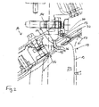
- a section of an aircraft engine 10 is shown. More specifically, in Fig. 1 Among other things, a housing 12 or that of a turbine intermediate housing (TCF) with a ring element 13 with a flange portion 14, and an annular segmented fairing 16 are shown.
- TCF turbine intermediate housing
- a hot gas channel 20 (TCF Flow Path) between the annular segmented panel 16 and the housing or the turbine intermediate housing (TCF) 12 via individual sealing strip segments 22, which are pressed by spring elements 24 to the sealing surface of the ring member 13
- a spring element 24 is shown which is attached to the panel 16 or an extension of the panel 16 respectively by a fastening pin 26 and a sealing strip segment 22 presses against the sealing surface of the ring member 13.
- a section of an aircraft engine 10 is shown. More specifically, in Fig. 2 In this case, a section of a housing 12 of a turbine intermediate housing (TCF) with a ring element 13 is shown (designed as a retaining ring of a guide blade), which has a flange portion 14. Furthermore, a vane device 17 of a turbine 18, here for example a vane device 17 with a vane stage 1 (Vane STG 1) 19 of a low-pressure turbine 18, and an annular, segmented casing 16 are shown.
- TCF turbine intermediate housing
- Vane STG 1 vane stage 1
- the segmented shroud 16 having the sealing means of the present invention has shroud segments 15 forming part of the outer ring of the gas channel 20 and shroud segments 25 covering the struts between an inner ring and the outer ring and between shroud segments 15 of the outer ring are arranged to form the outer ring of the gas channel 20.
- the cladding segments 15 which form part of the outer ring of the gas channel 20 are so-called outer panels or so-called outer cladding panels.
- the lining segments 25, which form the lining of the struts, are referred to as so-called fairing as described above.
- the inner ring of the gas channel 20 also has a segmented lining, with inner panels and the trim segments 25 therebetween.
- Fig. 2 a part of the housing 12 of the turbine intermediate housing (TCF) is shown.
- the housing 12 is connected to the separately formed ring element 13, which is integrally formed, that is not formed segmented, and the flange portion 14 has.
- the flange portion 14 may have a sealing portion 34 for the sealing device 30 as a receptacle.
- the sealing portion 34 has, for example, a cylindrical sealing surface for sealingly receiving the piston ring member 32.
- each of the trim segments 15, 25 of the outer ring trim 16 of the hot gas duct 20, i. the outer ring panels (so-called outer panels or outer cladding panels) and the fairing fairing segments 25 interposed therebetween have a receptacle 36 for the sealing means 30.
- the sealing device 30 has a piston ring element 32, which is received in the respective receptacle 36 of the segments 15, 25 of the panel 16.
- the receptacle 36 in the respective trim segment 15 and 25 is designed such that the outer diameter of the receptacle 36 is formed smaller than the inner diameter of the piston ring member 32, so that a gap 21 results in the radial direction between the piston ring member 32 and the receptacle 36th
- the radial gap 21 serves in this case, for example, to provide a radial play of the lining segments 15 and 25. This play is necessary in order to enable or permit radial thermal expansions and also radial component deviations (tolerances).
- the receptacle 36 is formed in the respective trim segment 15 and 25 such that its width is greater than the width of the piston ring element 32, so that a gap 23 in the axial direction between the receptacle 36 and the piston ring member 32 is given.
- the axial gap 23 serves, for example, to provide an axial play of the lining segments 15 and 25, which are assembled into a ring and the annular segmented panel 16 form to allow axial tolerances and not to impede different thermal expansion from segment to segment.
- the piston ring member 32 is received as a sealing means 30 in the seal receptacle 36 of the respective panel segment 15 and 25 of the panel 16 and sealingly abuts the associated sealing portion 34 of the ring member 13 of the housing 12 of the turbine intermediate housing (TCF).
- the ring member 13 and the housing 12 may also be formed so that the piston ring member 32 bears against this axially sealing.
- the panel segments 15 and 25 of the panel 16 can also be formed so that the piston ring member 32 bears against these radially sealing.
- the axial guidance of the piston ring element 32 in this case takes place via a seal receiver 36 in the housing or the ring element. This also applies to the following second embodiment of the invention.
- FIG. 3 Furthermore, a section of an aircraft engine 10 is shown, comparable to that in FIG Fig. 2 shown section.
- the sealing device 30 in contrast to the embodiment according to the invention in Fig. 2 a plurality of piston ring elements 32, for example, a first and second piston ring element 32nd
- Fig. 2 also shows Fig. 3 a section of a housing 12 of a turbine intermediate housing (TCF), however, the ring member 13 is, for example, integrally formed with the turbine housing 12 and not as in Fig. 2 provided as a separate part and attached to the housing 12, for example by means of screws.
- TCF turbine intermediate housing
- the cladding segments 25 are arranged between cladding segments 15.
- the lining segments 15, 25 each have a receptacle 36 for the two piston ring elements 32 of the sealing device 30.
- the first piston ring member 32 is sealingly on the housing 12 or its example, with the housing 12 integrally formed ring member 13 (sealing surface 34).
- the second piston ring element 32 in turn is sealingly against the respective trim segment 15 and 25.
- the second piston ring member 32 is sealingly attached to an associated sealing surface of the receptacle 36 of the respective panel segment 15, 25.
- the receptacle 36 in the respective trim segment 15, 25 is for example designed such that the outer diameter of the receptacle 36 is formed smaller than the inner diameter of the first piston ring member 32, so that a gap 21 results in the radial direction between the first piston ring member 32 and the Recording 36.
- the radial gap 21 serves, for example, for providing a radial play for the lining segments 15, 25.
- the first piston ring element lies in the radial direction in a sealing manner against the ring element 13 or the housing 12.
- the outer diameter of the receptacle 36 for example, equal to the inner diameter of the second piston ring member 32 or forms with this a transition fit, so that the second piston ring member 32 sealingly bears against the receptacle 36 or an associated sealing surface of the receptacle 36.
- the receptacle 36 in the respective trim segment 15, 25 is formed so that its width is greater than the width of the two piston ring elements 32 together, so that a gap 23 is given in the axial direction between the receptacle 36 and the two piston ring elements 32.
- the axial gap 23 serves, for example, to provide an axial clearance for the lining segments 15, 25, which, as described above, are assembled into a ring or outer ring and form the annular segmented lining 16 for the outer ring.
- the two piston ring elements 32 can now compensate for deviations in the radial direction. This means that if, for example, the lining segments 15, 25 in the radial direction move outward or expand in the radial direction, this radial expansion can be compensated by the two piston ring members 32 and the radial column 21 of the piston ring members 32.
- the first piston ring member 32 is sealingly on its outer periphery to the ring member 13 of the housing 12 and the second piston ring member 32 with its inner periphery sealingly against the receptacle 36 at.
- the first piston ring member 32 lies with its outer periphery sealingly against the ring member 13 of the housing 12 and the second piston ring member 32 is sealingly against the receptacle 36 with its inner periphery.
- the first piston ring member 32 in the axial direction also sealingly on the receptacle 36 at. Due to the axial play of the receptacle 36 is the second piston ring member 32, as in Fig. 2 For example, it is not shown sealingly on the receptacle 36.
- an expansion of the lining 16 and its lining segments 15, 25 are compensated or compensated in the axial direction and at the same time an axial seal between the panels 15, 25 and the housing 12 and its ring member 13 are provided.
- the piston ring pair 32 in Fig. 3 be designed so that a piston ring member 32 (here the second Kolberingelement 32) against the radial inner surface, here the seal holder 36 in Fig. 3 , spans and seals.
- the other piston ring element 32 (here the first piston ring element 32) can in turn be designed such that it presses against the radial outer surface and thus seals, here the sealing section 34 of the flange section 14 of the ring element 13 Fig. 3 which as a separate part or in one piece, as in Fig. 3 , may be formed with the housing 12.
- tolerance-related steps between the lining 16 or its lining segments 15, 25 and the piston ring elements 32 can be reproduced and thus lead to a further improvement of the sealing effect.
- the wear running-in process
- the piston ring members 32 may either seal against the axially elongated liner 16, as in FIG Fig. 3 is shown, or against the housing 12 and against the Ring element 13 dense to the interface to the turbine, eg here low pressure turbine (LPT) 18, not to influence and also to simplify the assembly.
- LPT low pressure turbine
- a reliable hot runner sealing between the turbine housing or turbine intermediate housing (TCF) and the turbine, here e.g. Low pressure turbine (LPT) can be provided.
- TCF turbine intermediate housing
- LPT Low pressure turbine
- a piston ring pair 32 as exemplified in Fig. 3 can be designed so that a ring 32 clamps and seals against a radially inner surface, the other presses against a radial Au- ⁇ enthesis 32 and thus seals. This is useful because the inner surface to be sealed, ie the surface of the panels 15, 25, is segmented here and thus, in contrast to normal applications of piston rings or piston ring elements 32, especially in the axial direction tolerances.
- seal construction is particularly suitable to endure the axial displacement occurring without loss of sealing effect.
- a hot gas collapse, for example, in areas can be avoided, which do not permanently withstand the hot gas temperatures, inevitably. This leads to a significant reduction in maintenance or maintenance costs.
- the maintenance costs are significantly reduced in particular by the fact that the piston ring element solution, for example in the examples in the Fig. 2 and 3 the life of the sealing segments in Fig. 1 significantly better.
- consequential damage such as cracks in the vane device 17, retaining ring element 13 and a repair of the housing of the turbine intermediate housing (TCF), for example by means of spraying or even a replacement (Replacement) can be avoided.
Landscapes
- Engineering & Computer Science (AREA)
- Mechanical Engineering (AREA)
- General Engineering & Computer Science (AREA)
- Turbine Rotor Nozzle Sealing (AREA)
Priority Applications (1)
| Application Number | Priority Date | Filing Date | Title |
|---|---|---|---|
| EP10195144A EP2466074A1 (fr) | 2010-12-15 | 2010-12-15 | Turbine à gaz dotée d'un dispositif d'étanchéité en forme de segment de piston |
Applications Claiming Priority (1)
| Application Number | Priority Date | Filing Date | Title |
|---|---|---|---|
| EP10195144A EP2466074A1 (fr) | 2010-12-15 | 2010-12-15 | Turbine à gaz dotée d'un dispositif d'étanchéité en forme de segment de piston |
Publications (1)
| Publication Number | Publication Date |
|---|---|
| EP2466074A1 true EP2466074A1 (fr) | 2012-06-20 |
Family
ID=43989839
Family Applications (1)
| Application Number | Title | Priority Date | Filing Date |
|---|---|---|---|
| EP10195144A Withdrawn EP2466074A1 (fr) | 2010-12-15 | 2010-12-15 | Turbine à gaz dotée d'un dispositif d'étanchéité en forme de segment de piston |
Country Status (1)
| Country | Link |
|---|---|
| EP (1) | EP2466074A1 (fr) |
Cited By (18)
| Publication number | Priority date | Publication date | Assignee | Title |
|---|---|---|---|---|
| EP2743459A1 (fr) * | 2012-12-11 | 2014-06-18 | MTU Aero Engines GmbH | Turbomachine |
| US10247019B2 (en) | 2017-02-23 | 2019-04-02 | General Electric Company | Methods and features for positioning a flow path inner boundary within a flow path assembly |
| US10253641B2 (en) | 2017-02-23 | 2019-04-09 | General Electric Company | Methods and assemblies for attaching airfoils within a flow path |
| US10253643B2 (en) | 2017-02-07 | 2019-04-09 | General Electric Company | Airfoil fluid curtain to mitigate or prevent flow path leakage |
| US10370990B2 (en) | 2017-02-23 | 2019-08-06 | General Electric Company | Flow path assembly with pin supported nozzle airfoils |
| US10371383B2 (en) * | 2017-01-27 | 2019-08-06 | General Electric Company | Unitary flow path structure |
| US10378373B2 (en) | 2017-02-23 | 2019-08-13 | General Electric Company | Flow path assembly with airfoils inserted through flow path boundary |
| US10385776B2 (en) | 2017-02-23 | 2019-08-20 | General Electric Company | Methods for assembling a unitary flow path structure |
| US10385709B2 (en) | 2017-02-23 | 2019-08-20 | General Electric Company | Methods and features for positioning a flow path assembly within a gas turbine engine |
| US10393381B2 (en) | 2017-01-27 | 2019-08-27 | General Electric Company | Unitary flow path structure |
| US10450897B2 (en) | 2016-07-18 | 2019-10-22 | General Electric Company | Shroud for a gas turbine engine |
| US10816199B2 (en) | 2017-01-27 | 2020-10-27 | General Electric Company | Combustor heat shield and attachment features |
| US10822973B2 (en) | 2017-11-28 | 2020-11-03 | General Electric Company | Shroud for a gas turbine engine |
| US11111858B2 (en) | 2017-01-27 | 2021-09-07 | General Electric Company | Cool core gas turbine engine |
| US11268394B2 (en) | 2020-03-13 | 2022-03-08 | General Electric Company | Nozzle assembly with alternating inserted vanes for a turbine engine |
| US11402097B2 (en) | 2018-01-03 | 2022-08-02 | General Electric Company | Combustor assembly for a turbine engine |
| US11428160B2 (en) | 2020-12-31 | 2022-08-30 | General Electric Company | Gas turbine engine with interdigitated turbine and gear assembly |
| US11739663B2 (en) | 2017-06-12 | 2023-08-29 | General Electric Company | CTE matching hanger support for CMC structures |
Citations (8)
| Publication number | Priority date | Publication date | Assignee | Title |
|---|---|---|---|---|
| DE972115C (de) * | 1954-10-23 | 1959-05-21 | Maschf Augsburg Nuernberg Ag | Axialdurchstroemte Turbine fuer heisse Treibmittel, insbesondere Gasturbine |
| DE2943464A1 (de) | 1978-10-30 | 1980-05-14 | Gen Electric | Dichtungsvorrichtung fuer ein gasturbinentriebwerk |
| DE3609578A1 (de) * | 1986-03-21 | 1987-08-27 | Daimler Benz Ag | Dichtung bei einer gasturbine |
| DE3939272A1 (de) * | 1989-11-28 | 1991-05-29 | Daimler Benz Ag | Dichtring |
| DE4100225A1 (de) * | 1991-01-07 | 1992-07-09 | Daimler Benz Ag | Vorrichtung zur abdichtung eines aus zwei ineinander geschobenen, rotationssymmetrischen gehaeuseteilen einer gasturbine gebildeten spaltes |
| EP1270875A2 (fr) | 2001-06-21 | 2003-01-02 | General Electric Company | Fixation d'une lame d'étanchéité dans une turbine avec des goupilles |
| DE60220636T2 (de) | 2002-03-01 | 2008-02-21 | General Electric Co. | Gasturbine mit gegenläufigen Niederdruckrotoren |
| EP1939404A2 (fr) * | 2006-12-19 | 2008-07-02 | United Technologies Corporation | Assemblage statorique |
-
2010
- 2010-12-15 EP EP10195144A patent/EP2466074A1/fr not_active Withdrawn
Patent Citations (8)
| Publication number | Priority date | Publication date | Assignee | Title |
|---|---|---|---|---|
| DE972115C (de) * | 1954-10-23 | 1959-05-21 | Maschf Augsburg Nuernberg Ag | Axialdurchstroemte Turbine fuer heisse Treibmittel, insbesondere Gasturbine |
| DE2943464A1 (de) | 1978-10-30 | 1980-05-14 | Gen Electric | Dichtungsvorrichtung fuer ein gasturbinentriebwerk |
| DE3609578A1 (de) * | 1986-03-21 | 1987-08-27 | Daimler Benz Ag | Dichtung bei einer gasturbine |
| DE3939272A1 (de) * | 1989-11-28 | 1991-05-29 | Daimler Benz Ag | Dichtring |
| DE4100225A1 (de) * | 1991-01-07 | 1992-07-09 | Daimler Benz Ag | Vorrichtung zur abdichtung eines aus zwei ineinander geschobenen, rotationssymmetrischen gehaeuseteilen einer gasturbine gebildeten spaltes |
| EP1270875A2 (fr) | 2001-06-21 | 2003-01-02 | General Electric Company | Fixation d'une lame d'étanchéité dans une turbine avec des goupilles |
| DE60220636T2 (de) | 2002-03-01 | 2008-02-21 | General Electric Co. | Gasturbine mit gegenläufigen Niederdruckrotoren |
| EP1939404A2 (fr) * | 2006-12-19 | 2008-07-02 | United Technologies Corporation | Assemblage statorique |
Cited By (28)
| Publication number | Priority date | Publication date | Assignee | Title |
|---|---|---|---|---|
| EP2743459A1 (fr) * | 2012-12-11 | 2014-06-18 | MTU Aero Engines GmbH | Turbomachine |
| US11994039B2 (en) | 2016-07-18 | 2024-05-28 | General Electric Company | Shroud for a gas turbine engine |
| US11306617B2 (en) | 2016-07-18 | 2022-04-19 | General Electric Company | Shroud for a gas turbine engine |
| US10450897B2 (en) | 2016-07-18 | 2019-10-22 | General Electric Company | Shroud for a gas turbine engine |
| US10816199B2 (en) | 2017-01-27 | 2020-10-27 | General Electric Company | Combustor heat shield and attachment features |
| US10371383B2 (en) * | 2017-01-27 | 2019-08-06 | General Electric Company | Unitary flow path structure |
| US11143402B2 (en) | 2017-01-27 | 2021-10-12 | General Electric Company | Unitary flow path structure |
| US11111858B2 (en) | 2017-01-27 | 2021-09-07 | General Electric Company | Cool core gas turbine engine |
| US10393381B2 (en) | 2017-01-27 | 2019-08-27 | General Electric Company | Unitary flow path structure |
| US10253643B2 (en) | 2017-02-07 | 2019-04-09 | General Electric Company | Airfoil fluid curtain to mitigate or prevent flow path leakage |
| US11149575B2 (en) | 2017-02-07 | 2021-10-19 | General Electric Company | Airfoil fluid curtain to mitigate or prevent flow path leakage |
| US10385776B2 (en) | 2017-02-23 | 2019-08-20 | General Electric Company | Methods for assembling a unitary flow path structure |
| US11384651B2 (en) | 2017-02-23 | 2022-07-12 | General Electric Company | Methods and features for positioning a flow path inner boundary within a flow path assembly |
| US10385709B2 (en) | 2017-02-23 | 2019-08-20 | General Electric Company | Methods and features for positioning a flow path assembly within a gas turbine engine |
| US10378373B2 (en) | 2017-02-23 | 2019-08-13 | General Electric Company | Flow path assembly with airfoils inserted through flow path boundary |
| US10370990B2 (en) | 2017-02-23 | 2019-08-06 | General Electric Company | Flow path assembly with pin supported nozzle airfoils |
| US11149569B2 (en) | 2017-02-23 | 2021-10-19 | General Electric Company | Flow path assembly with airfoils inserted through flow path boundary |
| US10247019B2 (en) | 2017-02-23 | 2019-04-02 | General Electric Company | Methods and features for positioning a flow path inner boundary within a flow path assembly |
| US11286799B2 (en) | 2017-02-23 | 2022-03-29 | General Electric Company | Methods and assemblies for attaching airfoils within a flow path |
| US10253641B2 (en) | 2017-02-23 | 2019-04-09 | General Electric Company | Methods and assemblies for attaching airfoils within a flow path |
| US11828199B2 (en) | 2017-02-23 | 2023-11-28 | General Electric Company | Methods and assemblies for attaching airfoils within a flow path |
| US11391171B2 (en) | 2017-02-23 | 2022-07-19 | General Electric Company | Methods and features for positioning a flow path assembly within a gas turbine engine |
| US11739663B2 (en) | 2017-06-12 | 2023-08-29 | General Electric Company | CTE matching hanger support for CMC structures |
| US10822973B2 (en) | 2017-11-28 | 2020-11-03 | General Electric Company | Shroud for a gas turbine engine |
| US11402097B2 (en) | 2018-01-03 | 2022-08-02 | General Electric Company | Combustor assembly for a turbine engine |
| US11846207B2 (en) | 2020-03-13 | 2023-12-19 | General Electric Company | Nozzle assembly with alternating inserted vanes for a turbine engine |
| US11268394B2 (en) | 2020-03-13 | 2022-03-08 | General Electric Company | Nozzle assembly with alternating inserted vanes for a turbine engine |
| US11428160B2 (en) | 2020-12-31 | 2022-08-30 | General Electric Company | Gas turbine engine with interdigitated turbine and gear assembly |
Similar Documents
| Publication | Publication Date | Title |
|---|---|---|
| EP2466074A1 (fr) | Turbine à gaz dotée d'un dispositif d'étanchéité en forme de segment de piston | |
| EP2696037B1 (fr) | Joint du canal d'écoulement d'une turbomachine | |
| DE102010016532A1 (de) | Turbinengehäuse mit Bolzenlagerung | |
| EP3152407B1 (fr) | Couronne d'aubes fixes, bague intérieure et turbomachine | |
| EP3051068A1 (fr) | Bague d'aube directrice pour une turbomachine et procédé de fabrication additive | |
| DE10318852A1 (de) | Hauptgaskanal-Innendichtung einer Hochdruckturbine | |
| DE102012102625A1 (de) | Rotationsbürstendichtung | |
| DE102004024683A1 (de) | Dichtungssystem für horizontale Verbindungsstellen von Zwischenböden von Dampfturbinen | |
| EP2647795A1 (fr) | Système d'étanchéité pour turbomachine | |
| EP2428647B1 (fr) | Zone de transition pour une chambre de combustion d'une turbine à gaz | |
| EP2360352B1 (fr) | Joint d'étanchéité sans vis d'une turbine à gaz | |
| EP2960555A1 (fr) | Système de joint à brosse pour sceller un intervalle entre les éléments d'une turbomachine qui peuvent être déplacés les uns par rapport aux autres | |
| EP2526263B1 (fr) | Système de boîtier pour une turbomachine axiale | |
| EP2284426B1 (fr) | Turbomachine | |
| EP3628030B1 (fr) | Méthode de maintenance d'une turbomachine | |
| DE102010036071A1 (de) | Gehäuseseitige Struktur einer Turbomaschine | |
| EP3670845B1 (fr) | Turbomachine avec agencement de joint statique | |
| EP2863019B1 (fr) | Agencement d'étanchéification | |
| EP2031189A1 (fr) | Joint d'étanchéité pour étanchéifier une fente entre les aubes directrices d'un stator d'une turbomachine axiale stationnaire et son rotor | |
| WO2007028353A1 (fr) | Turbomachine et element d'etancheite pour une turbomachine | |
| EP3587738B1 (fr) | Agencement d'étanchéité pour composants de turbomachine | |
| DE102013203870B4 (de) | Verdrehsicherung für Turbomaschinen | |
| EP3536913B1 (fr) | Bague intérieure pour une turbomachine et procédé de fabrication de cette bague intérieure | |
| EP4166754B1 (fr) | Ensemble rotor pour turbine à gaz avec surfaces de contact axiales inclinées formées sur des segments de rotor, turbine à gaz et turbine à gaz d'avion | |
| EP1790883A1 (fr) | Garniture d'étanchéité pour une turbo machine |
Legal Events
| Date | Code | Title | Description |
|---|---|---|---|
| PUAI | Public reference made under article 153(3) epc to a published international application that has entered the european phase |
Free format text: ORIGINAL CODE: 0009012 |
|
| AK | Designated contracting states |
Kind code of ref document: A1 Designated state(s): AL AT BE BG CH CY CZ DE DK EE ES FI FR GB GR HR HU IE IS IT LI LT LU LV MC MK MT NL NO PL PT RO RS SE SI SK SM TR |
|
| AX | Request for extension of the european patent |
Extension state: BA ME |
|
| 17P | Request for examination filed |
Effective date: 20121220 |
|
| RAP1 | Party data changed (applicant data changed or rights of an application transferred) |
Owner name: MTU AERO ENGINES AG |
|
| GRAP | Despatch of communication of intention to grant a patent |
Free format text: ORIGINAL CODE: EPIDOSNIGR1 |
|
| INTG | Intention to grant announced |
Effective date: 20170424 |
|
| STAA | Information on the status of an ep patent application or granted ep patent |
Free format text: STATUS: THE APPLICATION IS DEEMED TO BE WITHDRAWN |
|
| 18D | Application deemed to be withdrawn |
Effective date: 20170905 |