EP2960555A1 - Système de joint à brosse pour sceller un intervalle entre les éléments d'une turbomachine qui peuvent être déplacés les uns par rapport aux autres - Google Patents
Système de joint à brosse pour sceller un intervalle entre les éléments d'une turbomachine qui peuvent être déplacés les uns par rapport aux autres Download PDFInfo
- Publication number
- EP2960555A1 EP2960555A1 EP15169528.5A EP15169528A EP2960555A1 EP 2960555 A1 EP2960555 A1 EP 2960555A1 EP 15169528 A EP15169528 A EP 15169528A EP 2960555 A1 EP2960555 A1 EP 2960555A1
- Authority
- EP
- European Patent Office
- Prior art keywords
- brush seal
- seal system
- metal component
- brush
- sheet metal
- Prior art date
- Legal status (The legal status is an assumption and is not a legal conclusion. Google has not performed a legal analysis and makes no representation as to the accuracy of the status listed.)
- Granted
Links
Images
Classifications
-
- F—MECHANICAL ENGINEERING; LIGHTING; HEATING; WEAPONS; BLASTING
- F01—MACHINES OR ENGINES IN GENERAL; ENGINE PLANTS IN GENERAL; STEAM ENGINES
- F01D—NON-POSITIVE DISPLACEMENT MACHINES OR ENGINES, e.g. STEAM TURBINES
- F01D11/00—Preventing or minimising internal leakage of working-fluid, e.g. between stages
-
- F—MECHANICAL ENGINEERING; LIGHTING; HEATING; WEAPONS; BLASTING
- F01—MACHINES OR ENGINES IN GENERAL; ENGINE PLANTS IN GENERAL; STEAM ENGINES
- F01D—NON-POSITIVE DISPLACEMENT MACHINES OR ENGINES, e.g. STEAM TURBINES
- F01D11/00—Preventing or minimising internal leakage of working-fluid, e.g. between stages
- F01D11/001—Preventing or minimising internal leakage of working-fluid, e.g. between stages for sealing space between stator blade and rotor
-
- F—MECHANICAL ENGINEERING; LIGHTING; HEATING; WEAPONS; BLASTING
- F16—ENGINEERING ELEMENTS AND UNITS; GENERAL MEASURES FOR PRODUCING AND MAINTAINING EFFECTIVE FUNCTIONING OF MACHINES OR INSTALLATIONS; THERMAL INSULATION IN GENERAL
- F16J—PISTONS; CYLINDERS; SEALINGS
- F16J15/00—Sealings
- F16J15/16—Sealings between relatively-moving surfaces
- F16J15/32—Sealings between relatively-moving surfaces with elastic sealings, e.g. O-rings
- F16J15/3284—Sealings between relatively-moving surfaces with elastic sealings, e.g. O-rings characterised by their structure; Selection of materials
- F16J15/3288—Filamentary structures, e.g. brush seals
-
- F—MECHANICAL ENGINEERING; LIGHTING; HEATING; WEAPONS; BLASTING
- F05—INDEXING SCHEMES RELATING TO ENGINES OR PUMPS IN VARIOUS SUBCLASSES OF CLASSES F01-F04
- F05D—INDEXING SCHEME FOR ASPECTS RELATING TO NON-POSITIVE-DISPLACEMENT MACHINES OR ENGINES, GAS-TURBINES OR JET-PROPULSION PLANTS
- F05D2220/00—Application
- F05D2220/30—Application in turbines
- F05D2220/32—Application in turbines in gas turbines
-
- F—MECHANICAL ENGINEERING; LIGHTING; HEATING; WEAPONS; BLASTING
- F05—INDEXING SCHEMES RELATING TO ENGINES OR PUMPS IN VARIOUS SUBCLASSES OF CLASSES F01-F04
- F05D—INDEXING SCHEME FOR ASPECTS RELATING TO NON-POSITIVE-DISPLACEMENT MACHINES OR ENGINES, GAS-TURBINES OR JET-PROPULSION PLANTS
- F05D2240/00—Components
- F05D2240/55—Seals
- F05D2240/56—Brush seals
-
- Y—GENERAL TAGGING OF NEW TECHNOLOGICAL DEVELOPMENTS; GENERAL TAGGING OF CROSS-SECTIONAL TECHNOLOGIES SPANNING OVER SEVERAL SECTIONS OF THE IPC; TECHNICAL SUBJECTS COVERED BY FORMER USPC CROSS-REFERENCE ART COLLECTIONS [XRACs] AND DIGESTS
- Y02—TECHNOLOGIES OR APPLICATIONS FOR MITIGATION OR ADAPTATION AGAINST CLIMATE CHANGE
- Y02T—CLIMATE CHANGE MITIGATION TECHNOLOGIES RELATED TO TRANSPORTATION
- Y02T50/00—Aeronautics or air transport
- Y02T50/60—Efficient propulsion technologies, e.g. for aircraft
Definitions
- the invention relates to a brush seal system for sealing a gap between relatively movable components of a turbomachine, in particular a thermal gas turbine, comprising a brush seal housing, which accommodates at least one brush head of a brush seal, the brush seal housing a first sheet metal component with a cover plate portion and a second sheet metal component with a support plate portion includes.
- the invention further relates to a thermal gas turbine with such a brush seal system.
- Each brush seal housing consists for this purpose at least of a support plate and a cover plate, which are interconnected and together surround at least one brush head of the brush seal system U-shaped and secure against falling out of the brush seal housing.
- the cover plate or upstream in the flow direction region of the two-part brush seal housing is intended primarily disturbing flow influences on a brush head from the brush head and stand out of the brush seal housing protruding brush package, while downstream considered in the flow direction support plate of the brush seal housing serves as a support member, the bending of the brush package in the axial direction of the turbomachine, in particular the aircraft engine, due to the pressure difference across the To prevent brush seal housing.
- one-piece brush seal housing which are also at least approximately U-shaped in cross section.
- a disadvantage of the known brush seal systems is the fact that they usually have separately formed brush seal housing, which require a relatively large space, which is not present in every turbomachine and in particular in each engine application.
- Object of the present invention is therefore to provide a brush seal system of the type mentioned, which is designed such that it requires a relatively small space when installed in a turbomachine.
- Another object of the invention is to provide a thermal gas turbine with such a brush seal system.
- a first aspect of the invention relates to a brush seal system for sealing a gap between relatively movable components of a turbomachine, in particular a thermal gas turbine.
- the brush seal system according to the invention comprises a brush seal housing which accommodates at least one brush head of a brush seal, wherein the brush seal housing comprises a first sheet metal component with a cover sheet section and a second sheet metal component with a support sheet section.
- the first sheet metal part at an opposite end of the cover plate section on an axial flange to form a Fischmauldichtung.
- the axial flange acts as an example of a deflector of the fish mouth seal.
- Radial outward and opposite the axial flange is a radially inner platform of a vane assembly having one or more vanes to which the brush seal system is secured.
- Radial between the inner platform of the vane assembly and the axial flange may be an axial flange of an upstream and adjacent blade assembly having one or more blades.
- a lightweight construction is also possible, which is inexpensive executable by the sheet metal construction.
- the brush seal system according to the invention is suitable for the integration of a brush seal in an intermediate stage seal of a turbomachine, in particular a thermal gas turbine, from a lightweight construction aspect.
- the second sheet metal component at an opposite end of the support plate portion comprises a mounting portion for direct or indirect attachment of the brush seal system to a vane, a Leitschaufelcluster or a vane ring of the turbomachine.
- this embodiment of the brush seal system according to the invention can also assume an attachment function via the attachment section of the second sheet metal component.
- This integrated construction of the brush seal system of the present invention can advantageously replace the use of separately formed brush seal housings, fishmouth seals, and brush seal system fasteners on a vane, vane cluster, or vane ring.
- the brush seal housing is formed in several parts, in particular two parts, the structural design freedom of the brush seal system according to the invention can be further increased.
- this comprises at least one stiffening element, which is fixed to the second sheet-metal component in the region of the support plate portion. This allows the mechanical properties of the brush seal system can be significantly improved.
- the support plate section of the second sheet metal component has a support element for bearing against a brush pack of the brush seal.
- the support element is formed integrally with the support plate portion or as a separate element.
- the brush seal housing can be designed much more freely with regard to its structural mechanical behavior.
- Another advantage is that the brush seal system according to the invention can be particularly easily adapted to different purposes and engine types, since the same brush seal housing must be combined only with different brush seals and support elements to adapt the brush seal system, for example, to different sized radial gaps. The latter advantages also result in the case of the one-piece or integral design of the support element with the second sheet metal component.
- an end portion of the separately formed support member closer is arranged at an opposite end of the brush head of the brush package as an end portion of the second sheet metal component. In this way, it is ensured that, in the case of a possible rubbing, only the support element which is closer to the ends of the brush package, but not the second sheet metal component which is further removed from the ends of the brush package, is damaged.
- designs of the brush seal system that are substantially tolerant to slinging are made possible since, in the event of damage, no removal of the brush seal housing and of the brush seal is required.
- An additional increase in the constructive freedom is given in a further embodiment of the invention in that the separately formed support member is annular and / or ring-segment-shaped.
- a ring-segment-shaped configuration of the support element facilitates any repair especially since usually only a damaged ring segment, but not the entire ring must be repaired or replaced.
- the brush seal housing or the entire brush seal system can be formed segmented.
- the separately formed support member is made of a different material than the second sheet metal component and / or a different wall thickness than the second sheet metal component. Due to the free choice of material or the different wall thicknesses, the brush seal system can be made particularly variable and optimally adapted to different applications.
- the separately formed support element is arranged between the support plate portion and the stiffening element.
- the support element can be secured in position by a kind of clamping.
- the support element and the stiffening element can advantageously be determined here by means of a common fastening means on the support plate section of the second sheet metal component or on other regions of the second sheet metal component. As a result, a particularly fast, simple and inexpensive assembly and disassembly of the support element is possible.
- the stiffening element is formed as a bent metal sheet and / or that the stiffening element is riveted to the second sheet metal part of the brush seal housing and / or that between the stiffening element and the second sheet metal part of the brush seal housing at least one sliding element, in particular a sliding block is arranged.
- the stiffening element is formed as a bent metal sheet, can be structurally simple and inexpensive Way a resilient yielding stiffening of the brush seal housing can be achieved.
- the stiffening element is riveted to the second sheet metal component of the brush seal housing, a positive and cost-effective manner a positive and / or non-positive connection between the stiffening element and the brush seal housing is achieved in total.
- the bearing point is formed by the sliding element, in particular a sliding block, wherein the sliding block engages in the assembled state of the brush seal system in a corresponding groove of, for example, a vane or a guide vane cluster. Due to the memory centering caused by thermal influences relative dimensional changes between the coaxially arranged, and against each other to be sealed components - ie between a stator and a rotor - better compensated.
- the one or more sliding elements, in particular the sliding blocks may be formed as separate assemblies and be connected for example by riveting to the stiffening element.
- the first and second sheet metal components may be formed as separate components or in one piece.
- training as separate components can lead to a simplified replacement or repair of the individual parts or of the brush seal system as a whole.
- the first and second sheet metal component can be positively connected and / or cohesively connected to each other.
- a one-piece design of the first and second sheet metal components reduces the number of parts to be installed, resulting in a time advantage in the manufacture and installation of the brush seal system.
- the stiffening element comprises at an end opposite the abutment element an axial flange for forming a further, based on the position of the first Fischmauldichtung formed downstream of the first Fischmauldichtung Fischmauldichtung.
- the axial flange acts by way of example as a deflector of Fischmauldichtung.
- the radially outward and opposite axial flange of the axial flange is again the radially inner platform of the vane assembly having one or more vanes to which the brush seal system is secured via the attachment portion of the second sheet metal component.
- an axial flange of a downstream and adjacent blade assembly may be arranged with one or more blades.
- a second aspect of the invention relates to a thermal gas turbine, in particular an aircraft engine, with at least one brush seal system, which is designed according to the first aspect of the invention.
- the brush seal housing of the brush seal system is set to seal a gap between a rotor and a stator of the gas turbine on the stator.
- the brush seal housing directly or indirectly, is fixed to a stator of the gas turbine, so that the brush head opposite ends of the brush package rest on an associated surface of the rotor. This represents a mechanically particularly stable and reliable arrangement of the brush seal system.
- stator is designed as a guide blade and / or as a guide blade cluster and / or as a guide blade ring. If the stator is in segmented design, it has been found to be advantageous if the brush seal system is formed segmented, as this is a particularly simple assembly and disassembly is possible.
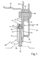
- Fig. 1 shows a schematic sectional view of a brush seal system 10 according to a first embodiment.
- the brush seal system 10 is used to seal a gap between relatively movable components of a turbomachine, in particular a thermal gas turbine.
- the components which are movable relative to one another are a rotor and a stator of a turbomachine, in particular an aircraft engine.
- the brush seal system 10 includes a brush seal housing 12 for receiving a brush head 14 of a brush seal 16.
- the brush seal housing 12 surrounds the brush seal 16 in a substantially U-shaped manner. It can be seen that the brush seal housing 12 is formed in two parts and comprises a first sheet metal component 18 with a cover plate section 20 and a second sheet metal component 26 with a support plate section 28.
- the cover plate portion 20 and the support plate portion 28 By means of the cover plate portion 20 and the support plate portion 28, the receptacle for the brush head 14 of the brush seal 16 is formed.
- the second sheet metal component 26 is arranged downstream of the first sheet metal component 18 in the flow direction.
- the first and second sheet metal components 18, 26 may also be formed in one piece. In the illustrated embodiment, the first and the second sheet metal component 18, 26 are positively connected to each other.
- the first sheet-metal component 18 comprises, at an end opposite the cover plate section 20, an axial flange 24 for forming a fish mouth seal.
- the term "axial flange" is to be interpreted such that the respective flange extends substantially parallel to an axis of a rotor 56 of the turbomachine.
- the axial flange 24 serves according to the embodiment as a deflector of the fish mouth seal.
- the radially outward and opposite axial flange 24 is a radially inner platform of a vane assembly having one or more vanes (not shown) to which the brush seal system 10 is secured. Radial between the inner platform of the vane assembly and the axial flange 24 may be an axial flange of an upstream and adjacent blade assembly having one or more blades (not shown).
- the second sheet metal component 26 has, at an end opposite the support plate section 28, a fastening section 30 for indirectly or directly fastening the brush seal system 10 to the guide vane arrangement of the turbomachine (not shown).
- the brush seal system 10 has a stiffening element 36, which is applied to the second sheet-metal component 26 in the region of the support plate section 28 via a contact element 40.
- the stiffening element 36 also has a base element 38, which extends in the illustrated embodiment in the radial direction substantially parallel to a central portion 34 of the second sheet metal component 26.
- the stiffening element 36 is formed as an approximately J-shaped bent metal sheet and connected via a rivet 44 with the second sheet metal component 26.
- a sliding element 42 designed as a sliding block is additionally arranged and also fixed by means of the rivet 44 on the brush sealing system 10.
- a radial flange 22 which is formed between the cover plate section 20 and the axial flange 24 as an integral part of the first sheet metal component 18, is connected to the first sheet metal component 18 and the stiffening element 36 via the rivet 44.
- the sliding element 42 represents a bearing point with a translational degree of freedom for spoke centering of the brush seal system 10.
- the sliding element 42 engages in a corresponding groove on the guide vane, a vane cluster or a vane ring (not shown) during assembly. Due to the spoke centering of the brush seal system 10, relative dimensional changes between the stator and rotor 56 caused by thermal influences can be better compensated.
- the brush seal system 10 of the invention is not limited to this type of mounting.
- the support plate portion 28, in the illustrated embodiment also has a support member 32 which is integrally formed with the support plate portion 28.
- the support member 32 is for abutment against a brush package 52 of the brush seal 16th
- the brush head 14 consists of a clamping tube 46, by means of which fiber or wire bundle 50 are fixed to a core wire 48.
- the fiber or wire bundles 50 protrude from the brush seal housing 12 and form the brush package 52, the end portion 54 of which can be brought into abutment with an associated sealing surface of the rotor 56 to seal an annular gap between the stator and rotor 56.
- the support plate section 28 serves with the support element 32. The support element 32 comes into contact with the brush pack 52.
- the brush seal system 10 may be formed annular segment-shaped.
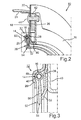
- Fig. 2 shows a schematic perspective view of a section through a brush seal system according to a second embodiment and will be in the following in conjunction with Fig. 3 in which an enlarged schematic view of the in Fig. 2 shown details III is shown.
- the support member 32 is formed as a separate element in the second embodiment of the brush seal system 10 shown here.
- the cover plate portion 20 of the first sheet metal component 18 is bent inwardly radially below the brush head 14, so that the brush head 14 and thus the brush seal 16 is held captive in the brush seal housing 12 and secured in position.
- the brush seal 16 can also be clamped between the cover plate section 20 and the support plate section 28, as shown in FIG Fig. 1 is shown.
- the brush head 14 in turn consists of the clamping tube 46, by means of which the fiber or wire bundle 50 are fixed to the core wire 48.
- the fiber or wire bundles 50 protrude from the brush seal housing 12 and form the brush package 52, the end portion 54 of which may in turn be brought into abutment with an associated sealing surface of a rotor (not shown) to seal an annular gap between the stator and the rotor.
- the support element 32 which has an upstream end portion bent in the direction of flow, against which the brush package 52 abuts, is arranged outside of the brush seal housing 12 and between the second sheet metal component 26 of the brush seal housing 12 and the stiffening element 36 is clamped and thereby secured in position. By this positive connection an exchange of the support member 32 is facilitated.
- the support element 32 which in the present case also has a ring-segment-shaped design analogously to the brush seal system 10, can also be connected to the second sheet metal component 26 and / or the stiffening element 36 in a materially bonded manner.
- the stiffening element 36 has, according to this embodiment, an approximately U-shaped abutment element 40, wherein a limb bears at least partially against a corresponding region of the second sheet metal component 26.
- the stiffening element 36 is again formed as a bent metal sheet and connected via the rivet 44 with the brush seal housing 12, that is, with the first and second sheet metal component 18, 26.
- a sliding element 42 in the form of a sliding block is again arranged and likewise fixed by means of the rivet 44 to the brush-sealing system 10.
- the radially inner end portion of the support member 32 is closer to an opposite end of the brush head 14 brush assembly 52 arranged as the corresponding, radially inner end portion of the second sheet metal component 26. This ensures that in the case of brushing on the rotor only the support member 32, not the second sheet metal component 26 or the brush seal housing 12 itself is affected. Due to the separate formation of the support member 32, a repair or replacement of the support member 32 are greatly facilitated after damage.
- the second sheet metal component 26 and the support member 32 are designed as separate components, a separation of the functionalities "housing or securing the brush seal 16" and "support of the brush package 52" is also given.
- the materials for the second sheet metal component 26 and for the separate support member 32 can be selected independently.
- the support member 32 may be made of a softer material than the second sheet metal component 26 to ensure a more grip-tolerant behavior of the brush seal system 10.
- the support element 32 does not have to be formed as a sheet metal or metal part, but may for example consist of a ceramic material or a ceramic fiber composite material or the like. Further advantages of the separation consist in the increase of the structural and geometric design freedom, so that, for example, different wall thicknesses, a different structural mechanical behavior during operation, different sealing effects and the like can be realized in a structurally simple and cost-effective manner.
- Brush seal system 10 with a separately formed support member 32 can be prepared by the following method: providing the brush seal housing 12 comprising the first and second sheet metal component 18, 26, arranging the brush seal 16, so that at least the brush head 14 of the brush seal 16 received in the brush seal housing 12 and secured in position Providing the separately formed support member 32 and arranging the support member 32 on the second sheet metal component 26 of the brush seal housing 12, so that the projecting from the brush head 14 of the brush seal 16 brush package 52 is supported by the support member 32 against deflection.
- a disassembly of the brush seal system 10 can be made in principle in reverse order.
Landscapes
- Engineering & Computer Science (AREA)
- General Engineering & Computer Science (AREA)
- Mechanical Engineering (AREA)
- Turbine Rotor Nozzle Sealing (AREA)
- Sealing Devices (AREA)
Applications Claiming Priority (1)
| Application Number | Priority Date | Filing Date | Title |
|---|---|---|---|
| DE102014212174.4A DE102014212174A1 (de) | 2014-06-25 | 2014-06-25 | Bürstendichtungssystem zum Abdichten eines Spalts zwischen relativ zueinander bewegbaren Bauteilen einer Strömungsmaschine |
Publications (2)
| Publication Number | Publication Date |
|---|---|
| EP2960555A1 true EP2960555A1 (fr) | 2015-12-30 |
| EP2960555B1 EP2960555B1 (fr) | 2021-06-30 |
Family
ID=53269330
Family Applications (1)
| Application Number | Title | Priority Date | Filing Date |
|---|---|---|---|
| EP15169528.5A Active EP2960555B1 (fr) | 2014-06-25 | 2015-05-28 | Système de joint à brosse pour sceller un intervalle entre les éléments d'une turbomachine qui peuvent être déplacés les uns par rapport aux autres |
Country Status (3)
| Country | Link |
|---|---|
| US (1) | US10094230B2 (fr) |
| EP (1) | EP2960555B1 (fr) |
| DE (1) | DE102014212174A1 (fr) |
Cited By (1)
| Publication number | Priority date | Publication date | Assignee | Title |
|---|---|---|---|---|
| RU2705103C1 (ru) * | 2019-04-05 | 2019-11-05 | Публичное акционерное общество "ОДК - Уфимское моторостроительное производственное объединение" (ПАО "ОДК - УМПО") | Щеточное уплотнение турбомашины |
Families Citing this family (6)
| Publication number | Priority date | Publication date | Assignee | Title |
|---|---|---|---|---|
| FR2998611B1 (fr) * | 2012-11-29 | 2018-08-10 | Safran Aircraft Engines | Ensemble formant joint d'etancheite pour une turbomachine comportant un joint a brosse |
| US10132183B2 (en) * | 2013-03-07 | 2018-11-20 | United Technologies Corporation | Brush seal repair method |
| PL3409897T3 (pl) | 2017-05-29 | 2020-04-30 | MTU Aero Engines AG | Uszczelka maszyny przepływowej, sposób wytwarzania uszczelki oraz maszyna przepływowa |
| ES2828719T3 (es) * | 2017-11-09 | 2021-05-27 | MTU Aero Engines AG | Disposición de sellado para una turbomáquina, método para la fabricación de una disposición de sellado y turbomáquina |
| DE102021129985A1 (de) * | 2021-11-17 | 2023-05-17 | MTU Aero Engines AG | Bürstendichtung mit anstreiftoleranter Stützringstruktur |
| DE102022124401A1 (de) * | 2022-09-22 | 2024-03-28 | MTU Aero Engines AG | Modul für eine strömungsmaschine |
Citations (5)
| Publication number | Priority date | Publication date | Assignee | Title |
|---|---|---|---|---|
| US20020020968A1 (en) | 2000-04-13 | 2002-02-21 | Alfons Gail | Brush seal |
| EP1347218A2 (fr) * | 2002-03-20 | 2003-09-24 | United Technologies Corporation | Joint d'étanchéité à brosse |
| WO2004101957A1 (fr) * | 2003-05-08 | 2004-11-25 | Mtu Aero Engines Gmbh | Systeme de joint a brosse a centrage par rayons dans une turbine a gaz |
| EP2722486A1 (fr) * | 2012-10-17 | 2014-04-23 | MTU Aero Engines GmbH | Support d'étanchéité pour ensemble statorique |
| EP2857721A1 (fr) * | 2013-10-07 | 2015-04-08 | MTU Aero Engines GmbH | Système de joint balai destiné à étanchéifier une fente entre des composants mobiles les uns par rapport aux autres d'une turbine à gaz thermique |
Family Cites Families (5)
| Publication number | Priority date | Publication date | Assignee | Title |
|---|---|---|---|---|
| US5215435A (en) * | 1991-10-28 | 1993-06-01 | General Electric Company | Angled cooling air bypass slots in honeycomb seals |
| US7938403B1 (en) * | 2009-12-31 | 2011-05-10 | General Electric Company | Brush seals |
| US8690527B2 (en) * | 2010-06-30 | 2014-04-08 | Honeywell International Inc. | Flow discouraging systems and gas turbine engines |
| DE102013213386B3 (de) * | 2013-07-09 | 2014-08-14 | MTU Aero Engines AG | Strömungsmaschinen-Keramikbauteil |
| DE102013217581A1 (de) * | 2013-09-04 | 2015-03-05 | MTU Aero Engines AG | Dichtungsanordnung in einer axialen Strömungsmaschine |
-
2014
- 2014-06-25 DE DE102014212174.4A patent/DE102014212174A1/de not_active Withdrawn
-
2015
- 2015-05-28 EP EP15169528.5A patent/EP2960555B1/fr active Active
- 2015-06-24 US US14/749,356 patent/US10094230B2/en active Active
Patent Citations (5)
| Publication number | Priority date | Publication date | Assignee | Title |
|---|---|---|---|---|
| US20020020968A1 (en) | 2000-04-13 | 2002-02-21 | Alfons Gail | Brush seal |
| EP1347218A2 (fr) * | 2002-03-20 | 2003-09-24 | United Technologies Corporation | Joint d'étanchéité à brosse |
| WO2004101957A1 (fr) * | 2003-05-08 | 2004-11-25 | Mtu Aero Engines Gmbh | Systeme de joint a brosse a centrage par rayons dans une turbine a gaz |
| EP2722486A1 (fr) * | 2012-10-17 | 2014-04-23 | MTU Aero Engines GmbH | Support d'étanchéité pour ensemble statorique |
| EP2857721A1 (fr) * | 2013-10-07 | 2015-04-08 | MTU Aero Engines GmbH | Système de joint balai destiné à étanchéifier une fente entre des composants mobiles les uns par rapport aux autres d'une turbine à gaz thermique |
Cited By (1)
| Publication number | Priority date | Publication date | Assignee | Title |
|---|---|---|---|---|
| RU2705103C1 (ru) * | 2019-04-05 | 2019-11-05 | Публичное акционерное общество "ОДК - Уфимское моторостроительное производственное объединение" (ПАО "ОДК - УМПО") | Щеточное уплотнение турбомашины |
Also Published As
| Publication number | Publication date |
|---|---|
| US10094230B2 (en) | 2018-10-09 |
| DE102014212174A1 (de) | 2015-12-31 |
| US20150377049A1 (en) | 2015-12-31 |
| EP2960555B1 (fr) | 2021-06-30 |
| US20170370236A9 (en) | 2017-12-28 |
Similar Documents
| Publication | Publication Date | Title |
|---|---|---|
| EP2960555B1 (fr) | Système de joint à brosse pour sceller un intervalle entre les éléments d'une turbomachine qui peuvent être déplacés les uns par rapport aux autres | |
| EP3020922B1 (fr) | Système de pale de turbomachine avec élément amorti | |
| EP2647795A1 (fr) | Système d'étanchéité pour turbomachine | |
| EP2722486A1 (fr) | Support d'étanchéité pour ensemble statorique | |
| EP2851518B1 (fr) | Modules d'une turbomachine | |
| DE102012102625A1 (de) | Rotationsbürstendichtung | |
| EP1143175A2 (fr) | Joint dans une réalisation non-hermétique | |
| EP2857721B1 (fr) | Système de joint balai destiné à étanchéifier une fente entre des composants mobiles les uns par rapport aux autres d'une turbine à gaz thermique | |
| DE102008057190A1 (de) | Schaufelcluster mit versetztem axialem Montagefuß | |
| DE102015212502A1 (de) | Verfahren zum Reinigen einer Radscheibenanordnung und/oder an dieser gehaltener Schaufeln | |
| EP3287608B1 (fr) | Bague intérieure d'une couronne d'aubes directrices d'une turbomachine | |
| EP3241995A1 (fr) | Segment d'aube directrice pour une turbo-machine | |
| EP3628030B1 (fr) | Méthode de maintenance d'une turbomachine | |
| EP2577117B1 (fr) | Procédé pour fixer un élément d'étanchéité à brosse dans une rainure d'un segment de boîtier | |
| DE102009007664A1 (de) | Abdichtvorrichtung an dem Schaufelschaft einer Rotorstufe einer axialen Strömungsmaschine | |
| DE102010005153A1 (de) | Gehäusesystem für eine Axialströmungsmaschine | |
| DE102013205880A1 (de) | Generativ hergestellte Dichtungsanordnung | |
| EP3115554A1 (fr) | Système d'aube avec des éléments de support élastiques pour une turbomachine thermique | |
| DE102023128456A1 (de) | Leitschaufel, Leitschaufelcluster und Gehäuse für eine Gasturbine sowie Gasturbine | |
| EP2787175B1 (fr) | Système de sécurité et procédé de sécurité d'une zone de fixation d'au moins une aube de rotor ou d'un segment d'aube de rotor dans une zone de montage d'un palier de rotor | |
| EP1890056A1 (fr) | Joint à brosses pour une turbomachine | |
| DE102019210753A1 (de) | Integral beschaufelter Turbomaschinen Rotor | |
| DE102018108655A1 (de) | Kolbenaufbau für einen Nehmerzylinder mit umgreifender Dichtung | |
| EP2980460B1 (fr) | Construction et fabrication générative d'un joint intégral | |
| DE102013216400A1 (de) | Leitschaufel mit einer Borsten umfassenden Dichteinrichtung |
Legal Events
| Date | Code | Title | Description |
|---|---|---|---|
| PUAI | Public reference made under article 153(3) epc to a published international application that has entered the european phase |
Free format text: ORIGINAL CODE: 0009012 |
|
| AK | Designated contracting states |
Kind code of ref document: A1 Designated state(s): AL AT BE BG CH CY CZ DE DK EE ES FI FR GB GR HR HU IE IS IT LI LT LU LV MC MK MT NL NO PL PT RO RS SE SI SK SM TR |
|
| AX | Request for extension of the european patent |
Extension state: BA ME |
|
| 17P | Request for examination filed |
Effective date: 20160629 |
|
| RBV | Designated contracting states (corrected) |
Designated state(s): AL AT BE BG CH CY CZ DE DK EE ES FI FR GB GR HR HU IE IS IT LI LT LU LV MC MK MT NL NO PL PT RO RS SE SI SK SM TR |
|
| STAA | Information on the status of an ep patent application or granted ep patent |
Free format text: STATUS: EXAMINATION IS IN PROGRESS |
|
| 17Q | First examination report despatched |
Effective date: 20161130 |
|
| REG | Reference to a national code |
Ref country code: DE Ref legal event code: R079 Ref document number: 502015014869 Country of ref document: DE Free format text: PREVIOUS MAIN CLASS: F16J0015320000 Ipc: F16J0015328800 |
|
| RIC1 | Information provided on ipc code assigned before grant |
Ipc: F16J 15/3288 20160101AFI20201106BHEP Ipc: F01D 11/00 20060101ALI20201106BHEP |
|
| GRAP | Despatch of communication of intention to grant a patent |
Free format text: ORIGINAL CODE: EPIDOSNIGR1 |
|
| STAA | Information on the status of an ep patent application or granted ep patent |
Free format text: STATUS: GRANT OF PATENT IS INTENDED |
|
| INTG | Intention to grant announced |
Effective date: 20210112 |
|
| GRAS | Grant fee paid |
Free format text: ORIGINAL CODE: EPIDOSNIGR3 |
|
| GRAA | (expected) grant |
Free format text: ORIGINAL CODE: 0009210 |
|
| STAA | Information on the status of an ep patent application or granted ep patent |
Free format text: STATUS: THE PATENT HAS BEEN GRANTED |
|
| AK | Designated contracting states |
Kind code of ref document: B1 Designated state(s): AL AT BE BG CH CY CZ DE DK EE ES FI FR GB GR HR HU IE IS IT LI LT LU LV MC MK MT NL NO PL PT RO RS SE SI SK SM TR |
|
| REG | Reference to a national code |
Ref country code: CH Ref legal event code: EP |
|
| REG | Reference to a national code |
Ref country code: AT Ref legal event code: REF Ref document number: 1406633 Country of ref document: AT Kind code of ref document: T Effective date: 20210715 |
|
| REG | Reference to a national code |
Ref country code: DE Ref legal event code: R096 Ref document number: 502015014869 Country of ref document: DE |
|
| REG | Reference to a national code |
Ref country code: IE Ref legal event code: FG4D Free format text: LANGUAGE OF EP DOCUMENT: GERMAN |
|
| REG | Reference to a national code |
Ref country code: LT Ref legal event code: MG9D |
|
| PG25 | Lapsed in a contracting state [announced via postgrant information from national office to epo] |
Ref country code: BG Free format text: LAPSE BECAUSE OF FAILURE TO SUBMIT A TRANSLATION OF THE DESCRIPTION OR TO PAY THE FEE WITHIN THE PRESCRIBED TIME-LIMIT Effective date: 20210930 Ref country code: FI Free format text: LAPSE BECAUSE OF FAILURE TO SUBMIT A TRANSLATION OF THE DESCRIPTION OR TO PAY THE FEE WITHIN THE PRESCRIBED TIME-LIMIT Effective date: 20210630 Ref country code: HR Free format text: LAPSE BECAUSE OF FAILURE TO SUBMIT A TRANSLATION OF THE DESCRIPTION OR TO PAY THE FEE WITHIN THE PRESCRIBED TIME-LIMIT Effective date: 20210630 |
|
| REG | Reference to a national code |
Ref country code: NL Ref legal event code: MP Effective date: 20210630 |
|
| PG25 | Lapsed in a contracting state [announced via postgrant information from national office to epo] |
Ref country code: NO Free format text: LAPSE BECAUSE OF FAILURE TO SUBMIT A TRANSLATION OF THE DESCRIPTION OR TO PAY THE FEE WITHIN THE PRESCRIBED TIME-LIMIT Effective date: 20210930 Ref country code: RS Free format text: LAPSE BECAUSE OF FAILURE TO SUBMIT A TRANSLATION OF THE DESCRIPTION OR TO PAY THE FEE WITHIN THE PRESCRIBED TIME-LIMIT Effective date: 20210630 Ref country code: SE Free format text: LAPSE BECAUSE OF FAILURE TO SUBMIT A TRANSLATION OF THE DESCRIPTION OR TO PAY THE FEE WITHIN THE PRESCRIBED TIME-LIMIT Effective date: 20210630 Ref country code: LV Free format text: LAPSE BECAUSE OF FAILURE TO SUBMIT A TRANSLATION OF THE DESCRIPTION OR TO PAY THE FEE WITHIN THE PRESCRIBED TIME-LIMIT Effective date: 20210630 Ref country code: GR Free format text: LAPSE BECAUSE OF FAILURE TO SUBMIT A TRANSLATION OF THE DESCRIPTION OR TO PAY THE FEE WITHIN THE PRESCRIBED TIME-LIMIT Effective date: 20211001 |
|
| PG25 | Lapsed in a contracting state [announced via postgrant information from national office to epo] |
Ref country code: SK Free format text: LAPSE BECAUSE OF FAILURE TO SUBMIT A TRANSLATION OF THE DESCRIPTION OR TO PAY THE FEE WITHIN THE PRESCRIBED TIME-LIMIT Effective date: 20210630 Ref country code: SM Free format text: LAPSE BECAUSE OF FAILURE TO SUBMIT A TRANSLATION OF THE DESCRIPTION OR TO PAY THE FEE WITHIN THE PRESCRIBED TIME-LIMIT Effective date: 20210630 Ref country code: CZ Free format text: LAPSE BECAUSE OF FAILURE TO SUBMIT A TRANSLATION OF THE DESCRIPTION OR TO PAY THE FEE WITHIN THE PRESCRIBED TIME-LIMIT Effective date: 20210630 Ref country code: EE Free format text: LAPSE BECAUSE OF FAILURE TO SUBMIT A TRANSLATION OF THE DESCRIPTION OR TO PAY THE FEE WITHIN THE PRESCRIBED TIME-LIMIT Effective date: 20210630 Ref country code: ES Free format text: LAPSE BECAUSE OF FAILURE TO SUBMIT A TRANSLATION OF THE DESCRIPTION OR TO PAY THE FEE WITHIN THE PRESCRIBED TIME-LIMIT Effective date: 20210630 Ref country code: PT Free format text: LAPSE BECAUSE OF FAILURE TO SUBMIT A TRANSLATION OF THE DESCRIPTION OR TO PAY THE FEE WITHIN THE PRESCRIBED TIME-LIMIT Effective date: 20211102 Ref country code: RO Free format text: LAPSE BECAUSE OF FAILURE TO SUBMIT A TRANSLATION OF THE DESCRIPTION OR TO PAY THE FEE WITHIN THE PRESCRIBED TIME-LIMIT Effective date: 20210630 Ref country code: NL Free format text: LAPSE BECAUSE OF FAILURE TO SUBMIT A TRANSLATION OF THE DESCRIPTION OR TO PAY THE FEE WITHIN THE PRESCRIBED TIME-LIMIT Effective date: 20210630 |
|
| PG25 | Lapsed in a contracting state [announced via postgrant information from national office to epo] |
Ref country code: PL Free format text: LAPSE BECAUSE OF FAILURE TO SUBMIT A TRANSLATION OF THE DESCRIPTION OR TO PAY THE FEE WITHIN THE PRESCRIBED TIME-LIMIT Effective date: 20210630 |
|
| REG | Reference to a national code |
Ref country code: DE Ref legal event code: R097 Ref document number: 502015014869 Country of ref document: DE |
|
| PG25 | Lapsed in a contracting state [announced via postgrant information from national office to epo] |
Ref country code: DK Free format text: LAPSE BECAUSE OF FAILURE TO SUBMIT A TRANSLATION OF THE DESCRIPTION OR TO PAY THE FEE WITHIN THE PRESCRIBED TIME-LIMIT Effective date: 20210630 |
|
| PLBE | No opposition filed within time limit |
Free format text: ORIGINAL CODE: 0009261 |
|
| STAA | Information on the status of an ep patent application or granted ep patent |
Free format text: STATUS: NO OPPOSITION FILED WITHIN TIME LIMIT |
|
| PG25 | Lapsed in a contracting state [announced via postgrant information from national office to epo] |
Ref country code: AL Free format text: LAPSE BECAUSE OF FAILURE TO SUBMIT A TRANSLATION OF THE DESCRIPTION OR TO PAY THE FEE WITHIN THE PRESCRIBED TIME-LIMIT Effective date: 20210630 |
|
| 26N | No opposition filed |
Effective date: 20220331 |
|
| PG25 | Lapsed in a contracting state [announced via postgrant information from national office to epo] |
Ref country code: IT Free format text: LAPSE BECAUSE OF FAILURE TO SUBMIT A TRANSLATION OF THE DESCRIPTION OR TO PAY THE FEE WITHIN THE PRESCRIBED TIME-LIMIT Effective date: 20210630 |
|
| REG | Reference to a national code |
Ref country code: CH Ref legal event code: PL |
|
| REG | Reference to a national code |
Ref country code: BE Ref legal event code: MM Effective date: 20220531 |
|
| PG25 | Lapsed in a contracting state [announced via postgrant information from national office to epo] |
Ref country code: MC Free format text: LAPSE BECAUSE OF FAILURE TO SUBMIT A TRANSLATION OF THE DESCRIPTION OR TO PAY THE FEE WITHIN THE PRESCRIBED TIME-LIMIT Effective date: 20210630 Ref country code: LU Free format text: LAPSE BECAUSE OF NON-PAYMENT OF DUE FEES Effective date: 20220528 Ref country code: LI Free format text: LAPSE BECAUSE OF NON-PAYMENT OF DUE FEES Effective date: 20220531 Ref country code: CH Free format text: LAPSE BECAUSE OF NON-PAYMENT OF DUE FEES Effective date: 20220531 |
|
| PG25 | Lapsed in a contracting state [announced via postgrant information from national office to epo] |
Ref country code: LT Free format text: LAPSE BECAUSE OF FAILURE TO SUBMIT A TRANSLATION OF THE DESCRIPTION OR TO PAY THE FEE WITHIN THE PRESCRIBED TIME-LIMIT Effective date: 20210630 Ref country code: IE Free format text: LAPSE BECAUSE OF NON-PAYMENT OF DUE FEES Effective date: 20220528 |
|
| PG25 | Lapsed in a contracting state [announced via postgrant information from national office to epo] |
Ref country code: BE Free format text: LAPSE BECAUSE OF NON-PAYMENT OF DUE FEES Effective date: 20220531 |
|
| REG | Reference to a national code |
Ref country code: AT Ref legal event code: MM01 Ref document number: 1406633 Country of ref document: AT Kind code of ref document: T Effective date: 20220528 |
|
| PG25 | Lapsed in a contracting state [announced via postgrant information from national office to epo] |
Ref country code: AT Free format text: LAPSE BECAUSE OF NON-PAYMENT OF DUE FEES Effective date: 20220528 |
|
| PGFP | Annual fee paid to national office [announced via postgrant information from national office to epo] |
Ref country code: DE Payment date: 20230519 Year of fee payment: 9 |
|
| PG25 | Lapsed in a contracting state [announced via postgrant information from national office to epo] |
Ref country code: HU Free format text: LAPSE BECAUSE OF FAILURE TO SUBMIT A TRANSLATION OF THE DESCRIPTION OR TO PAY THE FEE WITHIN THE PRESCRIBED TIME-LIMIT; INVALID AB INITIO Effective date: 20150528 |
|
| PG25 | Lapsed in a contracting state [announced via postgrant information from national office to epo] |
Ref country code: MK Free format text: LAPSE BECAUSE OF FAILURE TO SUBMIT A TRANSLATION OF THE DESCRIPTION OR TO PAY THE FEE WITHIN THE PRESCRIBED TIME-LIMIT Effective date: 20210630 Ref country code: CY Free format text: LAPSE BECAUSE OF FAILURE TO SUBMIT A TRANSLATION OF THE DESCRIPTION OR TO PAY THE FEE WITHIN THE PRESCRIBED TIME-LIMIT Effective date: 20210630 |
|
| PG25 | Lapsed in a contracting state [announced via postgrant information from national office to epo] |
Ref country code: TR Free format text: LAPSE BECAUSE OF FAILURE TO SUBMIT A TRANSLATION OF THE DESCRIPTION OR TO PAY THE FEE WITHIN THE PRESCRIBED TIME-LIMIT Effective date: 20210630 |
|
| PGFP | Annual fee paid to national office [announced via postgrant information from national office to epo] |
Ref country code: GB Payment date: 20240522 Year of fee payment: 10 |
|
| PGFP | Annual fee paid to national office [announced via postgrant information from national office to epo] |
Ref country code: FR Payment date: 20240522 Year of fee payment: 10 |
|
| PG25 | Lapsed in a contracting state [announced via postgrant information from national office to epo] |
Ref country code: MT Free format text: LAPSE BECAUSE OF FAILURE TO SUBMIT A TRANSLATION OF THE DESCRIPTION OR TO PAY THE FEE WITHIN THE PRESCRIBED TIME-LIMIT Effective date: 20210630 |
|
| REG | Reference to a national code |
Ref country code: DE Ref legal event code: R119 Ref document number: 502015014869 Country of ref document: DE |
|
| GBPC | Gb: european patent ceased through non-payment of renewal fee |
Effective date: 20250528 |
|
| PG25 | Lapsed in a contracting state [announced via postgrant information from national office to epo] |
Ref country code: GB Free format text: LAPSE BECAUSE OF NON-PAYMENT OF DUE FEES Effective date: 20250528 |
|
| PG25 | Lapsed in a contracting state [announced via postgrant information from national office to epo] |
Ref country code: DE Free format text: LAPSE BECAUSE OF NON-PAYMENT OF DUE FEES Effective date: 20251202 |
|
| PG25 | Lapsed in a contracting state [announced via postgrant information from national office to epo] |
Ref country code: FR Free format text: LAPSE BECAUSE OF NON-PAYMENT OF DUE FEES Effective date: 20250531 |