EP2466150A2 - Flügelrad für einen Ventilator sowie Verfahren zur Herstellung eines solchen Flügelrades - Google Patents
Flügelrad für einen Ventilator sowie Verfahren zur Herstellung eines solchen Flügelrades Download PDFInfo
- Publication number
- EP2466150A2 EP2466150A2 EP11009938A EP11009938A EP2466150A2 EP 2466150 A2 EP2466150 A2 EP 2466150A2 EP 11009938 A EP11009938 A EP 11009938A EP 11009938 A EP11009938 A EP 11009938A EP 2466150 A2 EP2466150 A2 EP 2466150A2
- Authority
- EP
- European Patent Office
- Prior art keywords
- flow element
- fan
- fan blade
- impeller
- flow
- Prior art date
- Legal status (The legal status is an assumption and is not a legal conclusion. Google has not performed a legal analysis and makes no representation as to the accuracy of the status listed.)
- Granted
Links
Images



Classifications
-
- F—MECHANICAL ENGINEERING; LIGHTING; HEATING; WEAPONS; BLASTING
- F04—POSITIVE - DISPLACEMENT MACHINES FOR LIQUIDS; PUMPS FOR LIQUIDS OR ELASTIC FLUIDS
- F04D—NON-POSITIVE-DISPLACEMENT PUMPS
- F04D29/00—Details, component parts, or accessories
- F04D29/26—Rotors specially for elastic fluids
- F04D29/32—Rotors specially for elastic fluids for axial flow pumps
- F04D29/38—Blades
- F04D29/384—Blades characterised by form
-
- F—MECHANICAL ENGINEERING; LIGHTING; HEATING; WEAPONS; BLASTING
- F04—POSITIVE - DISPLACEMENT MACHINES FOR LIQUIDS; PUMPS FOR LIQUIDS OR ELASTIC FLUIDS
- F04D—NON-POSITIVE-DISPLACEMENT PUMPS
- F04D29/00—Details, component parts, or accessories
- F04D29/08—Sealings
- F04D29/16—Sealings between pressure and suction sides
- F04D29/161—Sealings between pressure and suction sides especially adapted for elastic fluid pumps
- F04D29/164—Sealings between pressure and suction sides especially adapted for elastic fluid pumps of an axial flow wheel
-
- F—MECHANICAL ENGINEERING; LIGHTING; HEATING; WEAPONS; BLASTING
- F04—POSITIVE - DISPLACEMENT MACHINES FOR LIQUIDS; PUMPS FOR LIQUIDS OR ELASTIC FLUIDS
- F04D—NON-POSITIVE-DISPLACEMENT PUMPS
- F04D29/00—Details, component parts, or accessories
- F04D29/26—Rotors specially for elastic fluids
- F04D29/32—Rotors specially for elastic fluids for axial flow pumps
- F04D29/38—Blades
- F04D29/388—Blades characterised by construction
-
- F—MECHANICAL ENGINEERING; LIGHTING; HEATING; WEAPONS; BLASTING
- F04—POSITIVE - DISPLACEMENT MACHINES FOR LIQUIDS; PUMPS FOR LIQUIDS OR ELASTIC FLUIDS
- F04D—NON-POSITIVE-DISPLACEMENT PUMPS
- F04D29/00—Details, component parts, or accessories
- F04D29/66—Combating cavitation, whirls, noise, vibration or the like; Balancing
- F04D29/68—Combating cavitation, whirls, noise, vibration or the like; Balancing by influencing boundary layers
- F04D29/681—Combating cavitation, whirls, noise, vibration or the like; Balancing by influencing boundary layers especially adapted for elastic fluid pumps
-
- F—MECHANICAL ENGINEERING; LIGHTING; HEATING; WEAPONS; BLASTING
- F05—INDEXING SCHEMES RELATING TO ENGINES OR PUMPS IN VARIOUS SUBCLASSES OF CLASSES F01-F04
- F05D—INDEXING SCHEME FOR ASPECTS RELATING TO NON-POSITIVE-DISPLACEMENT MACHINES OR ENGINES, GAS-TURBINES OR JET-PROPULSION PLANTS
- F05D2230/00—Manufacture
- F05D2230/10—Manufacture by removing material
-
- F—MECHANICAL ENGINEERING; LIGHTING; HEATING; WEAPONS; BLASTING
- F05—INDEXING SCHEMES RELATING TO ENGINES OR PUMPS IN VARIOUS SUBCLASSES OF CLASSES F01-F04
- F05D—INDEXING SCHEME FOR ASPECTS RELATING TO NON-POSITIVE-DISPLACEMENT MACHINES OR ENGINES, GAS-TURBINES OR JET-PROPULSION PLANTS
- F05D2230/00—Manufacture
- F05D2230/80—Repairing, retrofitting or upgrading methods
-
- F—MECHANICAL ENGINEERING; LIGHTING; HEATING; WEAPONS; BLASTING
- F05—INDEXING SCHEMES RELATING TO ENGINES OR PUMPS IN VARIOUS SUBCLASSES OF CLASSES F01-F04
- F05D—INDEXING SCHEME FOR ASPECTS RELATING TO NON-POSITIVE-DISPLACEMENT MACHINES OR ENGINES, GAS-TURBINES OR JET-PROPULSION PLANTS
- F05D2240/00—Components
- F05D2240/20—Rotors
- F05D2240/30—Characteristics of rotor blades, i.e. of any element transforming dynamic fluid energy to or from rotational energy and being attached to a rotor
- F05D2240/304—Characteristics of rotor blades, i.e. of any element transforming dynamic fluid energy to or from rotational energy and being attached to a rotor related to the trailing edge of a rotor blade
-
- F—MECHANICAL ENGINEERING; LIGHTING; HEATING; WEAPONS; BLASTING
- F05—INDEXING SCHEMES RELATING TO ENGINES OR PUMPS IN VARIOUS SUBCLASSES OF CLASSES F01-F04
- F05D—INDEXING SCHEME FOR ASPECTS RELATING TO NON-POSITIVE-DISPLACEMENT MACHINES OR ENGINES, GAS-TURBINES OR JET-PROPULSION PLANTS
- F05D2240/00—Components
- F05D2240/20—Rotors
- F05D2240/30—Characteristics of rotor blades, i.e. of any element transforming dynamic fluid energy to or from rotational energy and being attached to a rotor
- F05D2240/307—Characteristics of rotor blades, i.e. of any element transforming dynamic fluid energy to or from rotational energy and being attached to a rotor related to the tip of a rotor blade
Definitions
- the invention relates to an impeller for a fan according to the preamble of claim 1 and to a method for producing such an impeller according to the preamble of claim 9.
- the invention has the object of providing the generic impeller and the generic method in such a way that vanes of different diameters can be produced inexpensively.
- the impeller according to the invention is characterized in that it has not only the flow element at the radially outer edge, but with Radial distance from it is provided with at least one further flow element.
- This further inward flow element lies on a suitable diameter for cutting the fan blade diameter, thus extending along an imaginary dividing line of the fan blade.
- the fan blades can be cut along the other flow element. In this way can be produced at low cost impellers with smaller diameter.
- the further flow element is located on the radially outer edge of the shortened fan blade.
- the smaller diameter fan thus has the same advantages in terms of excellent noise levels as the large diameter impeller. Thus, no separate, expensive tool is required to manufacture the small diameter impellers.
- the shortening of the wings is associated with no deterioration of the essential properties for the fan, such as low noise.
- the flow elements of the fan blades are similarly designed.
- the impellers with larger or smaller diameter thus also have correspondingly similar properties due to the similar design of the flow elements, which are located respectively at the radially outer edge of the fan blades.
- the flow elements of the fan blades are approximately parallel to one another.
- a particular embodiment results when the axial height of the one flow element, preferably all flow elements, in the region of the leading edge and the trailing edge of the fan blade has a maximum. Due to this design of the flow elements results in an excellent noise reduction when using the impeller and an optimal disability-free flow of air from the pressure to the suction side, whereby the noise reduction is favored.
- the ratio of the axial height of at least one flow element, preferably all flow elements, to the axial thickness of the fan blade in the region of the flow element in the region of the leading edge and / or the trailing edge decreases from.
- the height of the flow element can decrease to 0 in the area between the front and rear edge of the fan blade.
- the flow elements extend between the front and the rear edge of the fan blade.
- leading edge of the fan blade is at least partially concave over its length and / or the trailing edge of the fan blade is at least partially convex over its length. This design also contributes to the noise reduction of the fan during operation.
- the fan blades if a fan smaller diameter is required, along the other flow element cut so that this further flow element is located on the outer edge of the shortened fan blade. Due to this procedure, a fan wheel is produced with a smaller diameter, the fan blades are provided on the radially outer edge with a flow element. Then, the fan wheel with the smaller diameter has the same excellent properties as the fan whose fan blades are not shortened.
- the fan blade is cut through along the other flow element.
- the impeller described below is provided for a fan having a housing with a cylindrical shell enclosing a delivery channel.
- the impeller is housed in the delivery channel.
- the impeller has a hub 1 which is rotatably mounted on a shaft and rotatably driven in the direction of arrow 2.
- the fan blades 3 are distributed unevenly over the circumference of the hub 1.
- the impeller can also be designed in this way be that the fan blades 3 are arranged distributed uniformly over the circumference of the hub 1.
- the fan blades 3 each have a leading edge 2 in the direction of rotation 2 and a trailing edge 7 in the direction of rotation 2.
- the leading edge 6 is sickle-shaped, as viewed in the axial direction of the impeller, i. she has a concave course.
- the leading edge 6 extends from the hub 1 to the outer edge 8, which extends in the circumferential direction of the impeller.
- This outer edge 8 has a radial distance from the shell inner side of the fan housing. This distance is set so that the leakage flow is minimized and only a small noise occurs when the air flows from the pressure side 4 through the gap formed by the gap to the suction side 5.
- the region 9 at which the front edge 6 intersects the outer edge 8, in the direction of rotation 2 further forward than the connection region of the front edge 6 to the shell of the hub 1. If a radial is pulled through the axis of the impeller and through the corner region 9, then is, seen in the axial direction of the impeller, the connection region of the leading edge 6 to the hub shell in the direction of rotation 2 behind these radials.
- Such a design of the fan blades 3 results in a reduction in noise during operation of the fan and an improvement in the tearing behavior.
- the trailing edge 7 of the fan blade 3 is convex over at least part of its length.
- the convex course can be provided from the hub 1 to the outer edge 8 of the fan blade 3. It is also possible to provide the convex profile only over a partial length of the trailing edge 7 of the fan blade 3.
- the trailing edge 7 is provided over its length with teeth 10, each tapering towards its free end.
- the teeth 10 may have the same outline shape. Preferred are the teeth 10 are formed so that their advantageous pointed ends projecting up to a convex envelope line 11.
- the teeth 10 may also have different outline shapes and / or different lengths along the trailing edge 7. By appropriate choice of the design of the teeth 10, the noise of the fan can be optimally adapted to the particular application.
- the fan blades 3 are formed as a winding wing and advantageously curved.
- each fan blade 3 is provided with a transversely projecting flow element 12, which advantageously extends over the entire length of the outer edge 8 between the front edge 6 and the trailing edge 7.
- the flow elements 12 extend to the suction side 5 of the fan blade 3.
- the flow element 12 can extend both on the suction side 5 and on the pressure side 4. It is also possible that the flow element 12 projects only in the direction of the pressure side 4.
- the flow elements 12 are integrally formed with the fan blades 3, but can also be separate from the fan blades 3 components which are attached to the fan blades 3 in a suitable manner.
- the flow element 12 in the region of the front and the trailing edge 6, 7 each has its greatest height h, measured in the axial direction of the fan blade.
- the axial height h of the flow element 12 decreases from the leading edge 6 and the trailing edge 7, respectively, until the flow element 12 has the height 0 or approximately 0 in the region between the two edges 6, 7.
- This area can be half the width of the fan blade 3 lie.
- the fan blade 3 itself has a predetermined axial thickness d (in the area of the flow element 12). Fig. 5 ).
- the axial height h of the flow element 12 and the axial thickness d of the fan blade 3 are matched to one another such that the ratio h / d decreases from the front edge 6 and the trailing edge 7. In the region where the axial height h of the flow element 12 is close to 0, this ratio h / d is the lowest.
- the flow element 12 may also be designed so that its minimum axial height h is not half the width of the fan blade 3. It is essential that the ratio h / d decreases from the front edge 6 and the rear edge 7, respectively.
- Such a design of the fan blade 3 with flow element 12 results in an excellent noise reduction when used in the fan.
- the fan blades 3 have an aircraft wing profile shape. In the area of the front edge 6 of the fan blade 3 is rounded, while it expires in the region of the trailing edge 7 about pointed. In the area between the two edges 6, 7, the fan blade 3 can also have approximately constant cross-sectional thickness.
- the flow element 12 is designed such that its axial extent h increases greatly over a very short range from the front edge 6 of the fan blade 3 until the flow element 12 has its greatest axial height h at a small distance from the front edge 6. Similarly, the axial height h of the flow element 12 greatly increases from the trailing edge 7 over a very short range until the flow element 12 at a short distance from the trailing edge 7 has its greatest axial height h in that region, towards the center of the fan blade 3 decreases ( Fig. 5 ). Due to this design, the flow element 12 has a completely different course than the fan blade 3 in the region of the flow element 12.
- the fan blades 3 are provided with a radial distance from the flow element 12 with a further flow element 12 ', which is preferably the same
- the additional flow element 12 ' advantageously extends between the leading edge 6 and the trailing edge 7 and, like the flow element 12, is provided on the suction side 5 of the fan blade 3.
- the flow element 12 ' may likewise extend both to the suction side 5 and to the pressure side 4. It is also possible that the flow element 12 'projects only in the direction of the pressure side 4. It is advantageous if the two flow elements 12, 12 'are each arranged the same in relation to the fan blade 3.
- the additional flow element 12 ' makes it possible to tune the fan blades 3 to a second impeller diameter.
- the fan blades 3 are separated along the flow element 12 ', so that the flow element 12' is now located at the outer edge 8 'of the shorter fan blade 3.
- the fan blades 3 are sawed off along the flow element 12 '. Due to the sawing process, there is no disadvantage with regard to a noise development. It is of course possible to deburr the sawed area of the fan blade 3 or to rework it in some other way.
- the flow element 12 ' is advantageous integrally formed with the fan blade 3. But it can also be a separate from the fan blade 3 component, which is attached to the fan blade in a suitable manner.
- the shape of the flow element 12 'corresponds to the shape of the flow element 12, which is based on Fig. 5 is explained in more detail.
- the flow element 12 ' has in the region of the front and the rear edge 6, 7 of the fan blade 3 in each case its greatest height h', measured in the axial direction of the fan blade 3.
- the axial height h 'of the flow element 12' decreases in the region of the leading and trailing edges 6, 7, respectively, until the flow element 12 'between the two edges 6, 7 has the height 0 or approximately 0.
- This area can be in half the width of the fan blade 3.
- the fan blade 3 has the axial thickness d'. In the remaining radially inwardly adjoining region of the fan blades 3 may have different axial thickness.
- the axial height h 'and the axial thickness d' of the flow element 12 ' are matched to one another such that the ratio h' / d 'decreases from the front edge 6 and the trailing edge 7. In the area where the axial height h 'is close to 0, the ratio h' / d 'is lowest.
- the flow element 12 ' may be formed so that its minimum axial height h' is not half the width of the fan blade 3. It is also important for the flow element 12 'that the ratio h' / d 'of the front edge 6 and the trailing edge 7' decreases. Such a design results in an excellent noise reduction when using the fan with the shortened fan blades 3.
- the fan blade 3 is also provided in the region of the flow element 12 'with an aircraft wing profile shape, in which the fan blade 3 is rounded in the region of the front edge 6, while in the area the trailing edge is approximately pointed. In the area between the two edges 6, 7, the fan blade 3 can also have approximately constant cross-sectional thickness.
- the flow element 12 ' is likewise designed such that its axial extension from the front edge 6, starting from a very short range increases very much, until the flow element 12' at a small distance from the front edge 6 has its greatest axial height h '.
- the axial height h 'of the flow element 12' greatly increases from the trailing edge 7 over a very short range until the flow element 12 'has its greatest axial height h' a short distance from the trailing edge 7. It then decreases in the direction of the center of the fan blade 3. Due to this design, the flow element 12 'has a completely different course than the fan blade 3 in the region of the flow element 12'.
- the flow element 12 ' is provided so that it adjoins the trailing edge 7 in the region of the trailing edge 7 in the region between adjacent teeth 10.
- the fan blades 3 may be provided with at least one further flow element. Then there is the possibility that the fan blades can be made by sawing on the corresponding flow elements in different lengths. For these different lengths of fan blades again only a single tool is required, so that significant tool savings are possible.
Landscapes
- Engineering & Computer Science (AREA)
- Mechanical Engineering (AREA)
- General Engineering & Computer Science (AREA)
- Structures Of Non-Positive Displacement Pumps (AREA)
Abstract
Description
- Die Erfindung betrifft ein Flügelrad für einen Ventilator nach dem Oberbegriff des Anspruches 1 sowie ein Verfahren zur Herstellung eines solchen Flügelrades nach dem Oberbegriff des Anspruches 9.
- Es sind Flügelräder bekannt, deren Lüfterflügel am Außenrand mit quer abstehenden Strömungselementen versehen sind, die dafür sorgen, dass die mit solchen Flügelrädern ausgestatteten Ventilatoren geräuscharm arbeiten.
- Da je nach Größe der Ventilatoren Flügelräder unterschiedlicher Durchmesser benötigt werden, sind für die unterschiedlichen Flügelradgrößen auch unterschiedliche Werkzeuge zu deren Herstellung notwendig. Die Investitionskosten für solche Werkzeuge sind jedoch sehr hoch.
- Der Erfindung liegt die Aufgabe zugrunde, das gattungsgemäße Flügelrad sowie das gattungsgemäße Verfahren so auszubilden, dass Flügelräder unterschiedlichen Durchmessers kostengünstig hergestellt werden können.
- Diese Aufgabe wird beim gattungsgemäßen Flügelrad erfindungsgemäß mit den kennzeichnenden Merkmalen des Anspruches 1 und beim gattungsgemäßen Verfahren erfindungsgemäß mit den kennzeichnenden Merkmalen des Anspruches 9 gelöst.
- Das erfindungsgemäße Flügelrad zeichnet sich dadurch aus, dass es am radial äußeren Rand nicht nur das Strömungselement aufweist, sondern mit radialem Abstand von ihm mit wenigstens einem weiteren Strömungselement versehen ist. Dieses weiter innen liegende Strömungselement liegt auf einem zum Ablängen der Lüfterflügel geeigneten Durchmesser, erstreckt sich also entlang einer gedachten Trennlinie des Lüfterflügels. Die Lüfterflügel können längs des weiteren Strömungselementes durchtrennt werden. Auf diese Weise lassen sich kostengünstig Flügelräder mit kleinerem Durchmesser herstellen. Nach dem Ablängen liegt das weitere Strömungselement am radial äußeren Rand des gekürzten Lüfterflügels. Das Lüfterrad mit dem kleineren Durchmesser weist somit die gleichen Vorteile hinsichtlich hervorragender Geräuschwerte auf wie das Flügelrad mit großem Durchmesser. Zur Herstellung der Flügelräder mit kleinem Durchmesser ist somit kein gesondertes, teueres Werkzeug erforderlich. Das Kürzen der Flügel ist mit keiner Verschlechterung der für den Ventilator wesentlichen Eigenschaften, wie geringer Geräuschentwicklung, verbunden.
- Vorteilhaft sind die Strömungselemente der Lüfterflügel ähnlich ausgebildet. Die Flügelräder mit größerem oder kleinerem Durchmesser haben somit auch entsprechend gleiche Eigenschaften aufgrund der ähnlichen Gestaltung der Strömungselemente, die sich jeweils am radial äußeren Rand der Lüfterflügel befinden.
- Vorteilhaft verlaufen die Strömungselemente der Lüfterflügel etwa parallel zueinander.
- Eine besondere Ausführungsform ergibt sich, wenn die axiale Höhe des einen Strömungselementes, vorzugsweise aller Strömungselemente, im Bereich der Vorderkante und der Hinterkante des Lüfterflügels ein Maximum hat. Auf Grund dieser Gestaltung der Strömungselemente ergibt sich eine hervorragende Geräuschreduzierung beim Einsatz des Flügelrades sowie ein optimaler behinderungsfreier Durchfluss der Luft von der Druck- zur Saugseite, wodurch die Geräuschverringerung begünstigt wird.
- Bei einer besonderen Ausgestaltung nimmt das Verhältnis der axialen Höhe wenigstens des einen Strömungselementes, vorzugsweise aller Strömungselemente, zur axialen Dicke des Lüfterflügels im Bereich des Strömungselementes im Bereich von der Vorderkante und/oder der Hinterkante aus ab. Die Höhe des Strömungselementes kann bis auf 0 im Bereich zwischen Vorder- bzw. Hinterkante des Lüfterflügels abnehmen. Eine solche Ausbildung trägt zur Geräuschreduzierung sowie zum optimalen behinderungsfreien Durchfluss der Luft bei.
- Bei einer vorteilhaften Ausführungsform erstrecken sich die Strömungselemente zwischen der Vorder- und der Hinterkante des Lüfterflügels.
- Von Vorteil ist es, wenn die Vorderkante des Lüfterflügels über ihre Länge zumindest teilweise konkav und/oder die Hinterkante des Lüfterflügels über ihre Länge zumindest teilweise konvex ausgebildet ist. Auch diese Gestaltung trägt zur Geräuschverringerung des Ventilators im Betrieb bei.
- Beim erfindungsgemäßen Verfahren werden die Lüfterflügel, wenn ein Lüfterrad kleineren Durchmessers benötigt wird, längs des weiteren Strömungselementes so durchtrennt, dass dieses weitere Strömungselement am Außenrand des gekürzten Lüfterflügels liegt. Auf Grund dieser Verfahrensweise wird ein Lüfterrad mit kleinerem Durchmesser erzeugt, dessen Lüfterflügel am radial äußeren Rand mit einem Strömungselement versehen sind. Dann weist auch das Lüfterrad mit dem geringeren Durchmesser gleiche hervorragende Eigenschaften auf wie das Lüfterrad, dessen Lüfterflügel nicht gekürzt sind.
- Bei einer einfachen und kostengünstigen Verfahrensweise wird der Lüfterflügel längs des weiteren Strömungselementes durchgesägt.
- Weitere Merkmale der Erfindung ergeben sich aus den weiteren Ansprüchen, der Beschreibung und den Zeichnungen.
- Die Erfindung wird anhand eines in den Zeichnungen dargestellten Ausführungsbeispieles näher erläutert. Es zeigen
- Fig. 1
- eine Draufsicht auf die Saugseite eines erfindungsgemäßen Flügelrades,
- Fig. 2
- eine Seitenansicht des Flügelrades gemäß
Fig. 1 , - Fig. 3
- in vergrößerter Darstellung einen Teil eines Lüfterflügels des erfindungsgemäßen Flügelrades,
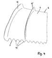
- Fig. 4
- in perspektivischer Darstellung den Lüfterflügel gemäß
Fig. 3 , - Fig. 5
- eine andere perspektivische Darstellung des Lüfterflügels gemäß
Fig. 3 . - Das im Folgenden beschriebene Flügelrad ist für einen Ventilator vorgesehen, der ein Gehäuse mit einem zylindrischen Mantel aufweist, der einen Förderkanal umschließt. Das Flügelrad ist im Förderkanal untergebracht.
- Das Flügelrad hat eine Nabe 1, das auf einer Welle drehfest gelagert und in Pfeilrichtung 2 drehbar angetrieben ist.
- Von der Nabe 1 stehen Lüfterflügel ab, die sich bis nahe an den Gehäusemantel des Ventilators erstrecken. Die Luft strömt zwischen dem radial äußeren Rand der Lüfterflügel 3 und der Innenseite des Gehäusemantels von der Druckseite 4 im Wesentlichen störungsfrei zur Saugseite 5 des Flügelrades (
Fig. 5 ). - Damit beim Betrieb des Ventilators die Geräuschentwicklung in einem für das menschliche Ohr angenehmen Frequenzspektrum liegt, ist es vorteilhaft, wenn die Lüfterflügel 3 über den Umfang der Nabe 1 ungleichmäßig verteilt sind. Das Flügelrad kann selbstverständlich auch so ausgebildet sein, dass die Lüfterflügel 3 gleichmäßig über den Umfang der Nabe 1 verteilt angeordnet sind.
- Die Lüfterflügel 3 haben jeweils eine in Drehrichtung 2 vorn liegende Vorderkante 6 sowie eine in Drehrichtung 2 hinten liegende Hinterkante 7. Die Vorderkante 6 ist, in Achsrichtung des Flügelrades gesehen, sichelförmig ausgebildet, d.h. sie hat einen konkaven Verlauf. Die Vorderkante 6 erstreckt sich von der Nabe 1 aus bis zum Außenrand 8, der sich in Umfangsrichtung des Flügelrades erstreckt. Dieser Außenrand 8 hat einen radialen Abstand von der Mantelinnenseite des Ventilatorgehäuses. Dieser Abstand ist so eingestellt, dass die Verlustströmung möglichst gering ist und eine nur geringe Geräuschentwicklung auftritt, wenn die Luft von der Druckseite 4 durch den durch den Abstand gebildeten Strömungsspalt zur Saugseite 5 strömt.
- Vorteilhaft liegt der Bereich 9, an dem die Vorderkante 6 den Außenrand 8 schneidet, in Drehrichtung 2 weiter vorn als der Anschlussbereich der Vorderkante 6 an den Mantel der Nabe 1. Wird eine Radiale durch die Achse des Flügelrades und durch den Eckbereich 9 gezogen, dann liegt, in Achsrichtung des Flügelrades gesehen, der Anschlussbereich der Vorderkante 6 an den Nabenmantel in Drehrichtung 2 hinter dieser Radialen. Durch eine solche Ausbildung der Lüfterflügel 3 ergibt sich eine Geräuschverringerung beim Betrieb des Ventilators und eine Verbesserung des Abrissverhaltens.
- Die Hinterkante 7 des Lüfterflügels 3 verläuft über mindestens einen Teil ihrer Länge konvex. Der konvexe Verlauf kann von der Nabe 1 bis zum Außenrand 8 des Lüfterflügels 3 vorgesehen sein. Es ist auch möglich, den konvexen Verlauf nur über eine Teillänge der Hinterkante 7 des Lüfterflügels 3 vorzusehen.
- Beim dargestellten Ausführungsbeispiel ist die Hinterkante 7 über ihre Länge mit Zähnen 10 versehen, die sich jeweils in Richtung auf ihr freies Ende verjüngen. Die Zähne 10 können gleiche Umrissform haben. Bevorzugt sind die Zähne 10 so ausgebildet, dass ihre vorteilhaft spitz auslaufenden Enden bis zu einer konvex verlaufenden Hülllinie 11 ragen.
- Die Zähne 10 können längs der Hinterkante 7 auch unterschiedliche Umrissformen und/oder unterschiedliche Länge haben. Durch entsprechende Wahl der Gestaltung der Zähne 10 lässt sich die Geräuschentwicklung des Ventilators an den jeweiligen Einsatzfall optimal anpassen.
- Wie
Fig. 2 zeigt, sind die Lüfterflügel 3 als gewundene Flügel und vorteilhaft gewölbt ausgebildet. - Am Außenrand 8 ist jeder Lüfterflügel 3 mit einem quer abstehenden Strömungselement 12 versehen, das sich vorteilhaft über die gesamte Länge des Außenrandes 8 zwischen der Vorderkante 6 und der Hinterkante 7 erstreckt. Die Strömungselemente 12 erstrecken sich zur Saugseite 5 des Lüfterflügels 3.
- Bei einer (nicht dargestellten) Ausführungsform kann sich das Strömungselement 12 sowohl auf die Saugseite 5 als auch auf die Druckseite 4 hin erstrecken. Es ist weiter möglich, dass das Strömungselement 12 lediglich in Richtung auf die Druckseite 4 ragt.
- Vorteilhaft sind die Strömungselemente 12 einstückig mit den Lüfterflügeln 3 ausgebildet, können aber auch vom Lüfterflügel 3 getrennte Bauteile sein, die an den Lüfterflügeln 3 in geeigneter Weise befestigt sind.
- Wie
Fig. 5 zeigt, hat das Strömungselement 12 im Bereich der Vorder- und der Hinterkante 6, 7 jeweils seine größte Höhe h, in Achsrichtung des Lüfterflügels gemessen. Die axiale Höhe h des Strömungselementes 12 nimmt von der Vorderkante 6 bzw. der Hinterkante 7 aus jeweils ab, bis das Strömungselement 12 im Bereich zwischen den beiden Kanten 6, 7 die Höhe 0 oder annähernd 0 hat. Dieser Bereich kann in halber Breite des Lüfterflügels 3 liegen. Der Lüfterflügel 3 selbst hat im Bereich des Strömungselementes 12 eine vorgegebene axiale Dicke d (Fig. 5 ). - Die axiale Höhe h des Strömungselementes 12 sowie die axiale Dicke d des Lüfterflügels 3 sind so auf einander abgestimmt, dass das Verhältnis h/d von der Vorderkante 6 sowie der Hinterkante 7 aus abnimmt. In dem Bereich, in dem die axiale Höhe h des Strömungselementes 12 nahezu 0 beträgt, ist dieses Verhältnis h/d am geringsten.
- Je nach Anwendungsfall kann das Strömungselement 12 auch so gestaltet sein, dass seine minimale axiale Höhe h nicht in halber Breite des Lüfterflügels 3 liegt. Wesentlich ist, dass das Verhältnis h/d von der Vorderkante 6 bzw. der Hinterkante 7 aus abnimmt. Durch eine solche Gestaltung des Lüfterflügels 3 mit Strömungselement 12 ergibt sich eine hervorragende Geräuschreduzierung beim Einsatz im Ventilator. Die Lüfterflügel 3 haben eine Flugzeugtragflächen-Profilform. Im Bereich der Vorderkante 6 ist der Lüfterflügels 3 abgerundet, während er im Bereich der Hinterkante 7 etwa spitz ausläuft. Im Bereich zwischen den beiden Kanten 6, 7 kann der Lüfterflügel 3 auch etwa konstante Querschnittsdicke haben. Das Strömungselement 12 ist so ausgebildet, dass seine axiale Erstreckung h von der Vorderkante 6 des Lüfterflügels 3 ausgehend über einen sehr kurzen Bereich stark zunimmt, bis das Strömungselement 12 mit geringem Abstand von der Vorderkante 6 seine größte axiale Höhe h aufweist. Ähnlich nimmt die axiale Höhe h des Strömungselementes 12 von der Hinterkante 7 aus über einen sehr kurzen Bereich sehr stark zu, bis das Strömungselement 12 mit geringem Abstand von der Hinterkante 7 in diesem Bereich seine größte axiale Höhe h aufweist, die in Richtung auf die Mitte des Lüfterflügels 3 abnimmt (
Fig. 5 ). Aufgrund dieser Ausbildung hat das Strömungselement 12 einen völlig anderen Verlauf als der Lüfterflügel 3 im Bereich des Strömungselementes 12. - Die Lüfterflügel 3 sind mit radialem Abstand zum Strömungselement 12 mit einem weiteren Strömungselement 12' versehen, das vorzugsweise gleich ausgebildet ist wie das Strömungselement 12 am Außenrand 8 des Lüfterflügels 3. Das zusätzliche Strömungselement 12' erstreckt sich vorteilhaft zwischen der Vorderkante 6 und der Hinterkante 7 und ist wie das Strömungselement 12 auf der Saugseite 5 des Lüfterflügels 3 vorgesehen. Das Strömungselement 12' kann sich ebenfalls sowohl auf die Saugseite 5 als auch auf die Druckseite 4 erstrecken. Ebenfalls ist es möglich, dass das Strömungselement 12' lediglich in Richtung auf die Druckseite 4 ragt. Von Vorteil ist es, wenn die beiden Strömungselemente 12, 12' jeweils gleich in Bezug auf den Lüfterflügel 3 angeordnet sind.
- Das zusätzliche Strömungselement 12' ermöglicht es, die Lüfterflügel 3 auf einen zweiten Laufraddurchmesser abzustimmen. Hierzu werden die Lüfterflügel 3 längs des Strömungselementes 12' abgetrennt, so dass das Strömungselement 12' sich nunmehr am Außenrand 8' des kürzeren Lüfterflügels 3 befindet. Die Lüfterflügel 3 werden längs des Strömungselementes 12' abgesägt. Durch den Sägevorgang entsteht kein Nachteil bezüglich einer Geräuschentwicklung. Es ist selbstverständlich möglich, den gesägten Bereich des Lüfterflügels 3 zu entgraten oder auf sonstige Weise nachzuarbeiten.
- Es ist somit nicht mehr erforderlich, für die unterschiedlich langen Lüfterflügel 3 jeweils ein Werkzeug vorzusehen. Es reicht ein Werkzeug aus, mit dem der Lüfterflügel 3 mit den Strömungselemente 12 und 12' hergestellt werden kann. Wird der kürzere Lüfterflügel 3 benötigt, wird er in der beschriebenen Weise längs des Strömungselementes 12' abgetrennt. Der entstehende Lüfterflügel 3 weist dann an seinem Außenrand 8' das Strömungselement 12' auf, das somit die gleichen Wirkungen hat wie das Strömungselement 12 beim längeren Lüfterflügel 3. Die anhand des Strömungselementes 12 beschriebenen Vorteile treten auch beim abgesägten Lüfterflügel 3 mit dem Strömungselement 12' auf.
- Aufgrund der beschriebenen Gestaltung der Lüfterflügel 3 werden erhebliche Kosten für die Werkzeuge eingespart. Das Strömungselement 12' ist vorteilhaft einstückig mit dem Lüfterflügel 3 ausgebildet. Es kann aber auch ein vom Lüfterflügel 3 getrenntes Bauteil sein, das am Lüfterflügel in geeigneter Weise befestigt wird.
- Die Form des Strömungselementes 12' entspricht der Form des Strömungselementes 12, was anhand von
Fig. 5 näher erläutert wird. - Das Strömungselement 12' hat im Bereich der Vorder- und der Hinterkante 6, 7 des Lüfterflügels 3 jeweils seine größte Höhe h', in Achsrichtung des Lüfterflügels 3 gemessen. Die axiale Höhe h' des Strömungselementes 12' nimmt im Bereich von der Vorder- und Hinterkante 6, 7 aus jeweils ab, bis das Strömungselement 12' zwischen den beiden Kanten 6, 7 die Höhe 0 oder annähernd 0 hat. Dieser Bereich kann in halber Breite des Lüfterflügels 3 liegen. Im Bereich des Strömungselementes 12' hat der Lüfterflügel 3 die axiale Dicke d'. Im übrigen radial nach innen anschließenden Bereich kann der Lüfterflügel 3 unterschiedliche axiale Dicke haben.
- Wie auch beim Strömungselement 12 sind beim Strömungselement 12' die axiale Höhe h' und die axiale Dicke d' so aufeinander abgestimmt, dass das Verhältnis h'/d' von der Vorderkante 6 sowie der Hinterkante 7 aus abnimmt. In dem Bereich, in dem die axiale Höhe h' nahezu 0 beträgt ist das Verhältnis h'/d' am geringsten.
- Je nach Anwendungsfall kann das Strömungselement 12' so ausgebildet sein, das seine minimale axiale Höhe h' nicht in halber Breite des Lüfterflügels 3 liegt. Wesentlich ist auch beim Strömungselement 12', dass das Verhältnis h'/d' von der Vorderkante 6 bzw. der Hinterkante 7' abnimmt. Durch eine solche Gestaltung ergibt sich eine hervorragende Geräuschreduzierung beim Einsatz des Ventilators mit den gekürzten Lüfterflügeln 3.
- Vorteilhaft ist der Lüfterflügel 3 auch im Bereich des Strömungselementes 12' mit einer Flugzeugtragflächen-Profilform versehen, bei der der Lüfterflügel 3 im Bereich der Vorderkante 6 abgerundet ist, während er im Bereich der Hinterkante etwa spitz ausläuft. Im Bereich zwischen den beiden Kanten 6, 7 kann der Lüfterflügel 3 auch etwa konstante Querschnittsdicke haben.
- Das Strömungselement 12' ist ebenfalls so ausgebildet, dass seine axiale Erstreckung von der Vorderkante 6 ausgehend über einen sehr kurzen Bereich sehr stark zunimmt, bis das Strömungselement 12' mit geringem Abstand von der Vorderkante 6 seine größte axiale Höhe h' aufweist. Ähnlich nimmt die axiale Höhe h' des Strömungselementes 12' von der Hinterkante 7 aus über einen sehr kurzen Bereich sehr stark zu, bis das Strömungselement 12' mit geringem Abstand von der Hinterkante 7 seine größte axiale Höhe h' aufweist. Sie nimmt dann in Richtung auf die Mitte des Lüfterflügels 3 ab. Aufgrund dieser Gestaltung hat das Strömungselement 12' einen völlig anderen Verlauf als der Lüfterflügel 3 im Bereich des Strömungselementes 12'.
- Im dargestellten Ausführungsbeispiel ist das Strömungselement 12' so vorgesehen, dass es im Bereich der Hinterkante 7 im Bereich zwischen benachbarten Zähnen 10 an die Hinterkante 7 anschließt.
- Die Lüfterflügel 3 können mit wenigstens einem weiteren Strömungselement versehen sein. Dann besteht die Möglichkeit, dass die Lüfterflügel durch Absägen an den entsprechenden Strömungselementen in unterschiedlichen Längen hergestellt werden können. Für diese unterschiedlichen Längen der Lüfterflügel ist wiederum nur ein einziges Werkzeug erforderlich, so dass erhebliche Werkzeugeinsparungen möglich sind.
- Wird das Flügelrad mit den langen Lüfterflügeln 3 verwendet, dann sorgen die weiteren Strömungselemente für ein hervorragendes Laufverhalten und für eine nur sehr geringe Geräuschentwicklung.
- Die Strömungselemente 12, 12' versteifen die ungekürzten Lüfterflügel 3. Sie können mit zusätzlichen Versteifungselementen 13 versehen sein (
Fig. 1 und5 ), die beispielsweise sickenförmig ausgebildet sind.
Claims (10)
- Flügelrad für einen Ventilator, das um eine Achse drehbar gelagert ist und eine Nabe aufweist, an der Lüfterflügel angeordnet sind, die am radial äußeren Rand mit wenigstens einem abstehenden Strömungselement versehen sind,
dadurch gekennzeichnet, dass die Lüfterflügel (3) mit radialem Abstand vom Strömungselement (12) wenigstens ein weiteres Strömungselement (12') aufweisen, das auf einem zum Ablängen der Lüfterflügel (3) geeigneten Durchmesser liegt. - Flügelrad nach Anspruch 1,
dadurch gekennzeichnet, dass die Strömungselemente (12, 12') ähnlich sind. - Flügelrad nach Anspruch 1 oder 2,
dadurch gekennzeichnet, dass die beiden Strömungselemente (12, 12') etwa parallel zueinander verlaufen. - Flügelrad nach einem der Ansprüche 1 bis 3,
dadurch gekennzeichnet, dass die axiale Höhe (h, h') zumindest des einen Strömungselementes (12, 12'), vorzugsweise aller Strömungselemente, im Bereich der Vorderkante (6) und der Hinterkante (7) des Lüfterflügels (3) ein Maximum hat. - Flügelrad, insbesondere nach einem der Ansprüche 1 bis 4,
dadurch gekennzeichnet, dass das Verhältnis der axialen Höhe (h, h') wenigstens des einen Strömungselementes (12, 12') , vorzugsweise aller Strömungselemente (12, 12'), zur axialen Dicke (d, d') des Lüfterflügels (3) im Bereich des Strömungselementes (12, 12') von der Vorderkante (6) und/oder der Hinterkante (7) des Lüfterflügels (3) aus abnimmt. - Flügelrad nach einem der Ansprüche 1 bis 5,
dadurch gekennzeichnet, dass sich die Strömungselemente (12, 12') zwischen der Vorderkante (6) und der Hinterkante (7) des Lüfterflügels (3) erstrecken. - Flügelrad nach einem der Ansprüche 1 bis 6,
dadurch gekennzeichnet, dass die Vorderkante (6) des Lüfterflügels (3) über ihre Länge zumindest teilweise konkav ausgebildet ist. - Flügelrad nach einem der Ansprüche 1 bis 7,
dadurch gekennzeichnet, dass die Hinterkante (7) des Lüfterflügels (3) über ihre Länge zumindest teilweise konvex ausgebildet ist. - Verfahren zur Herstellung eines Lüfterrades nach einem der Ansprüche 1 bis 8,
dadurch gekennzeichnet, dass die Lüfterflügel (3) längs des weiteren Strömungselementes (12') so durchtrennt werden, dass das weitere Strömungselement (12') am Außenrand (8') des gekürzten Lüfterflügels (3) liegt. - Verfahren nach Anspruch 9,
dadurch gekennzeichnet, dass der Lüfterflügel (3) längs des weiteren Strömungselementes (12') durchgesägt wird.
Priority Applications (1)
| Application Number | Priority Date | Filing Date | Title |
|---|---|---|---|
| SI201130946A SI2466150T1 (sl) | 2010-12-20 | 2011-12-16 | Postopek izdelave rotorja za ventilator |
Applications Claiming Priority (1)
| Application Number | Priority Date | Filing Date | Title |
|---|---|---|---|
| DE102010056145A DE102010056145A1 (de) | 2010-12-20 | 2010-12-20 | Flügelrad für einen Ventilator sowie Verfahren zur Herstellung eines solchen Flügelrades |
Publications (3)
| Publication Number | Publication Date |
|---|---|
| EP2466150A2 true EP2466150A2 (de) | 2012-06-20 |
| EP2466150A3 EP2466150A3 (de) | 2013-09-18 |
| EP2466150B1 EP2466150B1 (de) | 2016-06-01 |
Family
ID=45442766
Family Applications (1)
| Application Number | Title | Priority Date | Filing Date |
|---|---|---|---|
| EP11009938.9A Active EP2466150B1 (de) | 2010-12-20 | 2011-12-16 | Verfahren zur Herstellung eines Flügelrades für einen Ventilator |
Country Status (4)
| Country | Link |
|---|---|
| EP (1) | EP2466150B1 (de) |
| DE (1) | DE102010056145A1 (de) |
| ES (1) | ES2586878T3 (de) |
| SI (1) | SI2466150T1 (de) |
Cited By (9)
| Publication number | Priority date | Publication date | Assignee | Title |
|---|---|---|---|---|
| JP2016065536A (ja) * | 2014-09-18 | 2016-04-28 | 株式会社デンソー | 送風機 |
| CN106545521A (zh) * | 2017-01-16 | 2017-03-29 | 江苏汇创机电科技股份有限公司 | 一种无刷直流电机用降噪叶轮 |
| CN107489646A (zh) * | 2017-08-02 | 2017-12-19 | 奥克斯空调股份有限公司 | 锯齿型降噪轴流风叶 |
| CN107975494A (zh) * | 2017-11-22 | 2018-05-01 | 广东美的暖通设备有限公司 | 轴流风轮和空调 |
| CN111425454A (zh) * | 2020-03-31 | 2020-07-17 | Tcl空调器(中山)有限公司 | 轴流风叶和空调室外机 |
| CN112880097A (zh) * | 2021-01-18 | 2021-06-01 | 苏州新进元网络科技有限公司 | 一种除甲醛除异味功能空气清新设备 |
| US11187083B2 (en) | 2019-05-07 | 2021-11-30 | Carrier Corporation | HVAC fan |
| CN113864236A (zh) * | 2021-11-12 | 2021-12-31 | 珠海格力电器股份有限公司 | 一种风轮和出风装置 |
| USD980965S1 (en) | 2019-05-07 | 2023-03-14 | Carrier Corporation | Leading edge of a fan blade |
Families Citing this family (1)
| Publication number | Priority date | Publication date | Assignee | Title |
|---|---|---|---|---|
| DE102020210384A1 (de) | 2020-08-14 | 2022-02-17 | Robert Bosch Gesellschaft mit beschränkter Haftung | Verdichter und Verfahren zum Betreiben eines Verdichters |
Family Cites Families (8)
| Publication number | Priority date | Publication date | Assignee | Title |
|---|---|---|---|---|
| US3294175A (en) * | 1965-10-11 | 1966-12-27 | Charles H Bodner | Adjustable impeller |
| CN2377383Y (zh) * | 1998-06-19 | 2000-05-10 | 西北工业大学 | 一种轴流式风机叶片 |
| US20030012653A1 (en) * | 2001-07-13 | 2003-01-16 | Guy Diemunsch | Cooling fan |
| US7559744B2 (en) * | 2005-08-03 | 2009-07-14 | Mitsubishi Heavy Industries Ltd. | Propeller fan for heat exchanger of in-vehicle air conditioner |
| CN2839671Y (zh) * | 2005-08-19 | 2006-11-22 | 林钧浩 | 增压式轴流风机 |
| US20080253896A1 (en) * | 2007-04-13 | 2008-10-16 | Walls Gary C | High efficiency fan blades with airflow-directing baffle elements |
| DE102008008275A1 (de) * | 2008-02-07 | 2009-08-20 | Hägele GmbH | Lüfterflügel für Lüfterräder |
| DE202009003490U1 (de) * | 2009-03-13 | 2009-06-25 | Listan Asia Inc., Gueishan | Lüftermodul sowie Lüfterschaufelgruppe zur Strömungsführung hierfür |
-
2010
- 2010-12-20 DE DE102010056145A patent/DE102010056145A1/de not_active Ceased
-
2011
- 2011-12-16 ES ES11009938.9T patent/ES2586878T3/es active Active
- 2011-12-16 SI SI201130946A patent/SI2466150T1/sl unknown
- 2011-12-16 EP EP11009938.9A patent/EP2466150B1/de active Active
Non-Patent Citations (1)
| Title |
|---|
| None |
Cited By (13)
| Publication number | Priority date | Publication date | Assignee | Title |
|---|---|---|---|---|
| JP2016065536A (ja) * | 2014-09-18 | 2016-04-28 | 株式会社デンソー | 送風機 |
| CN106687693A (zh) * | 2014-09-18 | 2017-05-17 | 株式会社电装 | 送风机 |
| CN106545521A (zh) * | 2017-01-16 | 2017-03-29 | 江苏汇创机电科技股份有限公司 | 一种无刷直流电机用降噪叶轮 |
| CN106545521B (zh) * | 2017-01-16 | 2019-01-25 | 江苏汇创机电科技股份有限公司 | 一种无刷直流电机用降噪叶轮 |
| CN107489646A (zh) * | 2017-08-02 | 2017-12-19 | 奥克斯空调股份有限公司 | 锯齿型降噪轴流风叶 |
| CN107489646B (zh) * | 2017-08-02 | 2024-01-12 | 奥克斯空调股份有限公司 | 锯齿型降噪轴流风叶 |
| CN107975494A (zh) * | 2017-11-22 | 2018-05-01 | 广东美的暖通设备有限公司 | 轴流风轮和空调 |
| CN107975494B (zh) * | 2017-11-22 | 2020-08-25 | 广东美的暖通设备有限公司 | 轴流风轮和空调 |
| US11187083B2 (en) | 2019-05-07 | 2021-11-30 | Carrier Corporation | HVAC fan |
| USD980965S1 (en) | 2019-05-07 | 2023-03-14 | Carrier Corporation | Leading edge of a fan blade |
| CN111425454A (zh) * | 2020-03-31 | 2020-07-17 | Tcl空调器(中山)有限公司 | 轴流风叶和空调室外机 |
| CN112880097A (zh) * | 2021-01-18 | 2021-06-01 | 苏州新进元网络科技有限公司 | 一种除甲醛除异味功能空气清新设备 |
| CN113864236A (zh) * | 2021-11-12 | 2021-12-31 | 珠海格力电器股份有限公司 | 一种风轮和出风装置 |
Also Published As
| Publication number | Publication date |
|---|---|
| EP2466150A3 (de) | 2013-09-18 |
| EP2466150B1 (de) | 2016-06-01 |
| ES2586878T3 (es) | 2016-10-19 |
| DE102010056145A1 (de) | 2012-06-21 |
| SI2466150T1 (sl) | 2016-10-28 |
Similar Documents
| Publication | Publication Date | Title |
|---|---|---|
| EP2466150B1 (de) | Verfahren zur Herstellung eines Flügelrades für einen Ventilator | |
| EP2418389B1 (de) | Flügelrad für einen ventilator | |
| DE3137114C2 (de) | ||
| DE3412916C2 (de) | Lüfterflügel | |
| DE102012004617A1 (de) | Axialventilator | |
| DE202006011899U1 (de) | Ventilatorrad | |
| WO2017017264A1 (de) | Lüfterrad und kühlerlüftermodul | |
| WO2017093245A1 (de) | Lüfterrad für einen axiallüfter | |
| EP1788255A1 (de) | Radialverdichter-Laufrad | |
| EP2348220A1 (de) | Tauchpumpe | |
| EP3181911B1 (de) | Kantenberandung eines rotationselements und gebläserad | |
| DE10024741B4 (de) | Seitenkanalpumpe | |
| EP4154929B1 (de) | Atemtherapiegerät und lüftereinrichtung | |
| DE102014219058A1 (de) | Radialverdichterlaufrad und zugehöriger Radialverdichter | |
| EP2206929A1 (de) | Gebläseeinheit mit einem freien radialen gebläserad | |
| EP3312427B2 (de) | Ventilator mit ventilatorrad und leitrad | |
| WO2021259429A1 (de) | Ventilator sowie flügel und flügelrad für einen ventilator | |
| EP3114354B1 (de) | Lüfterrad eines axiallüfters | |
| EP0145857B1 (de) | Leitradloser Axialventilator, insbesondere zur Belüftung von Wärmetauschern | |
| DE202016105863U1 (de) | Ventilator mit Ventilatorrad und Leitrad | |
| EP0143235B1 (de) | Leitradloser Axialventilator, insbesondere zur Belüftung von Wärmetauschern | |
| DE3439780A1 (de) | Ventilator, insbesondere rohrventilator | |
| DE3906852C2 (de) | ||
| DE102007037012B4 (de) | Gebläseeinheit und handgetragenes Blasgerät | |
| WO2013143671A1 (de) | Ventilator, insbesondere für den einsatz in der klima- und kältetechnik |
Legal Events
| Date | Code | Title | Description |
|---|---|---|---|
| PUAI | Public reference made under article 153(3) epc to a published international application that has entered the european phase |
Free format text: ORIGINAL CODE: 0009012 |
|
| AK | Designated contracting states |
Kind code of ref document: A2 Designated state(s): AL AT BE BG CH CY CZ DE DK EE ES FI FR GB GR HR HU IE IS IT LI LT LU LV MC MK MT NL NO PL PT RO RS SE SI SK SM TR |
|
| AX | Request for extension of the european patent |
Extension state: BA ME |
|
| PUAL | Search report despatched |
Free format text: ORIGINAL CODE: 0009013 |
|
| AK | Designated contracting states |
Kind code of ref document: A3 Designated state(s): AL AT BE BG CH CY CZ DE DK EE ES FI FR GB GR HR HU IE IS IT LI LT LU LV MC MK MT NL NO PL PT RO RS SE SI SK SM TR |
|
| AX | Request for extension of the european patent |
Extension state: BA ME |
|
| RIC1 | Information provided on ipc code assigned before grant |
Ipc: F04D 29/68 20060101ALI20130814BHEP Ipc: F04D 29/16 20060101ALI20130814BHEP Ipc: F04D 29/38 20060101AFI20130814BHEP |
|
| RAP1 | Party data changed (applicant data changed or rights of an application transferred) |
Owner name: ZIEHL-ABEGG SE |
|
| RAP1 | Party data changed (applicant data changed or rights of an application transferred) |
Owner name: ZIEHL-ABEGG SE |
|
| 17P | Request for examination filed |
Effective date: 20140318 |
|
| RBV | Designated contracting states (corrected) |
Designated state(s): AL AT BE BG CH CY CZ DE DK EE ES FI FR GB GR HR HU IE IS IT LI LT LU LV MC MK MT NL NO PL PT RO RS SE SI SK SM TR |
|
| 17Q | First examination report despatched |
Effective date: 20150225 |
|
| GRAP | Despatch of communication of intention to grant a patent |
Free format text: ORIGINAL CODE: EPIDOSNIGR1 |
|
| INTG | Intention to grant announced |
Effective date: 20151221 |
|
| GRAS | Grant fee paid |
Free format text: ORIGINAL CODE: EPIDOSNIGR3 |
|
| GRAA | (expected) grant |
Free format text: ORIGINAL CODE: 0009210 |
|
| AK | Designated contracting states |
Kind code of ref document: B1 Designated state(s): AL AT BE BG CH CY CZ DE DK EE ES FI FR GB GR HR HU IE IS IT LI LT LU LV MC MK MT NL NO PL PT RO RS SE SI SK SM TR |
|
| REG | Reference to a national code |
Ref country code: GB Ref legal event code: FG4D Free format text: NOT ENGLISH |
|
| REG | Reference to a national code |
Ref country code: CH Ref legal event code: EP Ref country code: AT Ref legal event code: REF Ref document number: 804057 Country of ref document: AT Kind code of ref document: T Effective date: 20160615 |
|
| REG | Reference to a national code |
Ref country code: IE Ref legal event code: FG4D Free format text: LANGUAGE OF EP DOCUMENT: GERMAN |
|
| REG | Reference to a national code |
Ref country code: DE Ref legal event code: R096 Ref document number: 502011009855 Country of ref document: DE |
|
| REG | Reference to a national code |
Ref country code: LT Ref legal event code: MG4D |
|
| REG | Reference to a national code |
Ref country code: NL Ref legal event code: MP Effective date: 20160601 |
|
| REG | Reference to a national code |
Ref country code: ES Ref legal event code: FG2A Ref document number: 2586878 Country of ref document: ES Kind code of ref document: T3 Effective date: 20161019 |
|
| PG25 | Lapsed in a contracting state [announced via postgrant information from national office to epo] |
Ref country code: FI Free format text: LAPSE BECAUSE OF FAILURE TO SUBMIT A TRANSLATION OF THE DESCRIPTION OR TO PAY THE FEE WITHIN THE PRESCRIBED TIME-LIMIT Effective date: 20160601 Ref country code: LT Free format text: LAPSE BECAUSE OF FAILURE TO SUBMIT A TRANSLATION OF THE DESCRIPTION OR TO PAY THE FEE WITHIN THE PRESCRIBED TIME-LIMIT Effective date: 20160601 Ref country code: NO Free format text: LAPSE BECAUSE OF FAILURE TO SUBMIT A TRANSLATION OF THE DESCRIPTION OR TO PAY THE FEE WITHIN THE PRESCRIBED TIME-LIMIT Effective date: 20160901 |
|
| PG25 | Lapsed in a contracting state [announced via postgrant information from national office to epo] |
Ref country code: HR Free format text: LAPSE BECAUSE OF FAILURE TO SUBMIT A TRANSLATION OF THE DESCRIPTION OR TO PAY THE FEE WITHIN THE PRESCRIBED TIME-LIMIT Effective date: 20160601 Ref country code: NL Free format text: LAPSE BECAUSE OF FAILURE TO SUBMIT A TRANSLATION OF THE DESCRIPTION OR TO PAY THE FEE WITHIN THE PRESCRIBED TIME-LIMIT Effective date: 20160601 Ref country code: SE Free format text: LAPSE BECAUSE OF FAILURE TO SUBMIT A TRANSLATION OF THE DESCRIPTION OR TO PAY THE FEE WITHIN THE PRESCRIBED TIME-LIMIT Effective date: 20160601 Ref country code: RS Free format text: LAPSE BECAUSE OF FAILURE TO SUBMIT A TRANSLATION OF THE DESCRIPTION OR TO PAY THE FEE WITHIN THE PRESCRIBED TIME-LIMIT Effective date: 20160601 Ref country code: LV Free format text: LAPSE BECAUSE OF FAILURE TO SUBMIT A TRANSLATION OF THE DESCRIPTION OR TO PAY THE FEE WITHIN THE PRESCRIBED TIME-LIMIT Effective date: 20160601 Ref country code: GR Free format text: LAPSE BECAUSE OF FAILURE TO SUBMIT A TRANSLATION OF THE DESCRIPTION OR TO PAY THE FEE WITHIN THE PRESCRIBED TIME-LIMIT Effective date: 20160902 |
|
| REG | Reference to a national code |
Ref country code: FR Ref legal event code: PLFP Year of fee payment: 6 |
|
| PG25 | Lapsed in a contracting state [announced via postgrant information from national office to epo] |
Ref country code: IS Free format text: LAPSE BECAUSE OF FAILURE TO SUBMIT A TRANSLATION OF THE DESCRIPTION OR TO PAY THE FEE WITHIN THE PRESCRIBED TIME-LIMIT Effective date: 20161001 Ref country code: SK Free format text: LAPSE BECAUSE OF FAILURE TO SUBMIT A TRANSLATION OF THE DESCRIPTION OR TO PAY THE FEE WITHIN THE PRESCRIBED TIME-LIMIT Effective date: 20160601 Ref country code: CZ Free format text: LAPSE BECAUSE OF FAILURE TO SUBMIT A TRANSLATION OF THE DESCRIPTION OR TO PAY THE FEE WITHIN THE PRESCRIBED TIME-LIMIT Effective date: 20160601 Ref country code: RO Free format text: LAPSE BECAUSE OF FAILURE TO SUBMIT A TRANSLATION OF THE DESCRIPTION OR TO PAY THE FEE WITHIN THE PRESCRIBED TIME-LIMIT Effective date: 20160601 Ref country code: EE Free format text: LAPSE BECAUSE OF FAILURE TO SUBMIT A TRANSLATION OF THE DESCRIPTION OR TO PAY THE FEE WITHIN THE PRESCRIBED TIME-LIMIT Effective date: 20160601 |
|
| PG25 | Lapsed in a contracting state [announced via postgrant information from national office to epo] |
Ref country code: SM Free format text: LAPSE BECAUSE OF FAILURE TO SUBMIT A TRANSLATION OF THE DESCRIPTION OR TO PAY THE FEE WITHIN THE PRESCRIBED TIME-LIMIT Effective date: 20160601 Ref country code: PL Free format text: LAPSE BECAUSE OF FAILURE TO SUBMIT A TRANSLATION OF THE DESCRIPTION OR TO PAY THE FEE WITHIN THE PRESCRIBED TIME-LIMIT Effective date: 20160601 Ref country code: PT Free format text: LAPSE BECAUSE OF FAILURE TO SUBMIT A TRANSLATION OF THE DESCRIPTION OR TO PAY THE FEE WITHIN THE PRESCRIBED TIME-LIMIT Effective date: 20161003 |
|
| REG | Reference to a national code |
Ref country code: DE Ref legal event code: R097 Ref document number: 502011009855 Country of ref document: DE |
|
| PLBE | No opposition filed within time limit |
Free format text: ORIGINAL CODE: 0009261 |
|
| STAA | Information on the status of an ep patent application or granted ep patent |
Free format text: STATUS: NO OPPOSITION FILED WITHIN TIME LIMIT |
|
| 26N | No opposition filed |
Effective date: 20170302 |
|
| PG25 | Lapsed in a contracting state [announced via postgrant information from national office to epo] |
Ref country code: BE Free format text: LAPSE BECAUSE OF NON-PAYMENT OF DUE FEES Effective date: 20161231 Ref country code: DK Free format text: LAPSE BECAUSE OF FAILURE TO SUBMIT A TRANSLATION OF THE DESCRIPTION OR TO PAY THE FEE WITHIN THE PRESCRIBED TIME-LIMIT Effective date: 20160601 |
|
| REG | Reference to a national code |
Ref country code: CH Ref legal event code: PL |
|
| PG25 | Lapsed in a contracting state [announced via postgrant information from national office to epo] |
Ref country code: MC Free format text: LAPSE BECAUSE OF FAILURE TO SUBMIT A TRANSLATION OF THE DESCRIPTION OR TO PAY THE FEE WITHIN THE PRESCRIBED TIME-LIMIT Effective date: 20160601 |
|
| REG | Reference to a national code |
Ref country code: IE Ref legal event code: MM4A |
|
| REG | Reference to a national code |
Ref country code: FR Ref legal event code: PLFP Year of fee payment: 7 |
|
| PG25 | Lapsed in a contracting state [announced via postgrant information from national office to epo] |
Ref country code: LU Free format text: LAPSE BECAUSE OF NON-PAYMENT OF DUE FEES Effective date: 20161216 Ref country code: LI Free format text: LAPSE BECAUSE OF NON-PAYMENT OF DUE FEES Effective date: 20161231 Ref country code: CH Free format text: LAPSE BECAUSE OF NON-PAYMENT OF DUE FEES Effective date: 20161231 |
|
| PG25 | Lapsed in a contracting state [announced via postgrant information from national office to epo] |
Ref country code: IE Free format text: LAPSE BECAUSE OF NON-PAYMENT OF DUE FEES Effective date: 20161216 |
|
| REG | Reference to a national code |
Ref country code: BE Ref legal event code: MM Effective date: 20161231 |
|
| REG | Reference to a national code |
Ref country code: AT Ref legal event code: MM01 Ref document number: 804057 Country of ref document: AT Kind code of ref document: T Effective date: 20161216 |
|
| PG25 | Lapsed in a contracting state [announced via postgrant information from national office to epo] |
Ref country code: HU Free format text: LAPSE BECAUSE OF FAILURE TO SUBMIT A TRANSLATION OF THE DESCRIPTION OR TO PAY THE FEE WITHIN THE PRESCRIBED TIME-LIMIT; INVALID AB INITIO Effective date: 20111216 Ref country code: CY Free format text: LAPSE BECAUSE OF FAILURE TO SUBMIT A TRANSLATION OF THE DESCRIPTION OR TO PAY THE FEE WITHIN THE PRESCRIBED TIME-LIMIT Effective date: 20160601 Ref country code: AT Free format text: LAPSE BECAUSE OF NON-PAYMENT OF DUE FEES Effective date: 20161216 |
|
| PG25 | Lapsed in a contracting state [announced via postgrant information from national office to epo] |
Ref country code: TR Free format text: LAPSE BECAUSE OF FAILURE TO SUBMIT A TRANSLATION OF THE DESCRIPTION OR TO PAY THE FEE WITHIN THE PRESCRIBED TIME-LIMIT Effective date: 20160601 Ref country code: MK Free format text: LAPSE BECAUSE OF FAILURE TO SUBMIT A TRANSLATION OF THE DESCRIPTION OR TO PAY THE FEE WITHIN THE PRESCRIBED TIME-LIMIT Effective date: 20160601 |
|
| PG25 | Lapsed in a contracting state [announced via postgrant information from national office to epo] |
Ref country code: BG Free format text: LAPSE BECAUSE OF FAILURE TO SUBMIT A TRANSLATION OF THE DESCRIPTION OR TO PAY THE FEE WITHIN THE PRESCRIBED TIME-LIMIT Effective date: 20160601 |
|
| PG25 | Lapsed in a contracting state [announced via postgrant information from national office to epo] |
Ref country code: MT Free format text: LAPSE BECAUSE OF FAILURE TO SUBMIT A TRANSLATION OF THE DESCRIPTION OR TO PAY THE FEE WITHIN THE PRESCRIBED TIME-LIMIT Effective date: 20160601 |
|
| PG25 | Lapsed in a contracting state [announced via postgrant information from national office to epo] |
Ref country code: AL Free format text: LAPSE BECAUSE OF FAILURE TO SUBMIT A TRANSLATION OF THE DESCRIPTION OR TO PAY THE FEE WITHIN THE PRESCRIBED TIME-LIMIT Effective date: 20160601 |
|
| P01 | Opt-out of the competence of the unified patent court (upc) registered |
Effective date: 20231115 |
|
| PGFP | Annual fee paid to national office [announced via postgrant information from national office to epo] |
Ref country code: GB Payment date: 20251114 Year of fee payment: 15 |
|
| PGFP | Annual fee paid to national office [announced via postgrant information from national office to epo] |
Ref country code: IT Payment date: 20251203 Year of fee payment: 15 |
|
| PGFP | Annual fee paid to national office [announced via postgrant information from national office to epo] |
Ref country code: FR Payment date: 20251103 Year of fee payment: 15 |
|
| PGFP | Annual fee paid to national office [announced via postgrant information from national office to epo] |
Ref country code: SI Payment date: 20251212 Year of fee payment: 15 |
|
| PGFP | Annual fee paid to national office [announced via postgrant information from national office to epo] |
Ref country code: ES Payment date: 20260109 Year of fee payment: 15 |
|
| PGFP | Annual fee paid to national office [announced via postgrant information from national office to epo] |
Ref country code: DE Payment date: 20260225 Year of fee payment: 15 |