EP4154929B1 - Atemtherapiegerät und lüftereinrichtung - Google Patents
Atemtherapiegerät und lüftereinrichtung Download PDFInfo
- Publication number
- EP4154929B1 EP4154929B1 EP22195097.5A EP22195097A EP4154929B1 EP 4154929 B1 EP4154929 B1 EP 4154929B1 EP 22195097 A EP22195097 A EP 22195097A EP 4154929 B1 EP4154929 B1 EP 4154929B1
- Authority
- EP
- European Patent Office
- Prior art keywords
- channel
- housing
- partition wall
- respiratory therapy
- flow
- Prior art date
- Legal status (The legal status is an assumption and is not a legal conclusion. Google has not performed a legal analysis and makes no representation as to the accuracy of the status listed.)
- Active
Links
Images




Classifications
-
- A—HUMAN NECESSITIES
- A61—MEDICAL OR VETERINARY SCIENCE; HYGIENE
- A61M—DEVICES FOR INTRODUCING MEDIA INTO, OR ONTO, THE BODY; DEVICES FOR TRANSDUCING BODY MEDIA OR FOR TAKING MEDIA FROM THE BODY; DEVICES FOR PRODUCING OR ENDING SLEEP OR STUPOR
- A61M16/00—Devices for influencing the respiratory system of patients by gas treatment, e.g. ventilators; Tracheal tubes
- A61M16/0057—Pumps therefor
- A61M16/0066—Blowers or centrifugal pumps
-
- F—MECHANICAL ENGINEERING; LIGHTING; HEATING; WEAPONS; BLASTING
- F04—POSITIVE - DISPLACEMENT MACHINES FOR LIQUIDS; PUMPS FOR LIQUIDS OR ELASTIC FLUIDS
- F04D—NON-POSITIVE-DISPLACEMENT PUMPS
- F04D29/00—Details, component parts, or accessories
- F04D29/40—Casings; Connections of working fluid
- F04D29/42—Casings; Connections of working fluid for radial or helico-centrifugal pumps
- F04D29/44—Fluid-guiding means, e.g. diffusers
- F04D29/441—Fluid-guiding means, e.g. diffusers especially adapted for elastic fluid pumps
- F04D29/444—Bladed diffusers
-
- F—MECHANICAL ENGINEERING; LIGHTING; HEATING; WEAPONS; BLASTING
- F04—POSITIVE - DISPLACEMENT MACHINES FOR LIQUIDS; PUMPS FOR LIQUIDS OR ELASTIC FLUIDS
- F04D—NON-POSITIVE-DISPLACEMENT PUMPS
- F04D29/00—Details, component parts, or accessories
- F04D29/66—Combating cavitation, whirls, noise, vibration or the like; Balancing
- F04D29/661—Combating cavitation, whirls, noise, vibration or the like; Balancing especially adapted for elastic fluid pumps
- F04D29/663—Sound attenuation
-
- F—MECHANICAL ENGINEERING; LIGHTING; HEATING; WEAPONS; BLASTING
- F04—POSITIVE - DISPLACEMENT MACHINES FOR LIQUIDS; PUMPS FOR LIQUIDS OR ELASTIC FLUIDS
- F04D—NON-POSITIVE-DISPLACEMENT PUMPS
- F04D29/00—Details, component parts, or accessories
- F04D29/66—Combating cavitation, whirls, noise, vibration or the like; Balancing
- F04D29/661—Combating cavitation, whirls, noise, vibration or the like; Balancing especially adapted for elastic fluid pumps
- F04D29/667—Combating cavitation, whirls, noise, vibration or the like; Balancing especially adapted for elastic fluid pumps by influencing the flow pattern, e.g. suppression of turbulence
-
- F—MECHANICAL ENGINEERING; LIGHTING; HEATING; WEAPONS; BLASTING
- F04—POSITIVE - DISPLACEMENT MACHINES FOR LIQUIDS; PUMPS FOR LIQUIDS OR ELASTIC FLUIDS
- F04D—NON-POSITIVE-DISPLACEMENT PUMPS
- F04D29/00—Details, component parts, or accessories
- F04D29/66—Combating cavitation, whirls, noise, vibration or the like; Balancing
- F04D29/68—Combating cavitation, whirls, noise, vibration or the like; Balancing by influencing boundary layers
- F04D29/681—Combating cavitation, whirls, noise, vibration or the like; Balancing by influencing boundary layers especially adapted for elastic fluid pumps
-
- A—HUMAN NECESSITIES
- A61—MEDICAL OR VETERINARY SCIENCE; HYGIENE
- A61M—DEVICES FOR INTRODUCING MEDIA INTO, OR ONTO, THE BODY; DEVICES FOR TRANSDUCING BODY MEDIA OR FOR TAKING MEDIA FROM THE BODY; DEVICES FOR PRODUCING OR ENDING SLEEP OR STUPOR
- A61M16/00—Devices for influencing the respiratory system of patients by gas treatment, e.g. ventilators; Tracheal tubes
- A61M16/021—Devices for influencing the respiratory system of patients by gas treatment, e.g. ventilators; Tracheal tubes operated by electrical means
- A61M16/022—Control means therefor
-
- A—HUMAN NECESSITIES
- A61—MEDICAL OR VETERINARY SCIENCE; HYGIENE
- A61M—DEVICES FOR INTRODUCING MEDIA INTO, OR ONTO, THE BODY; DEVICES FOR TRANSDUCING BODY MEDIA OR FOR TAKING MEDIA FROM THE BODY; DEVICES FOR PRODUCING OR ENDING SLEEP OR STUPOR
- A61M2205/00—General characteristics of the apparatus
- A61M2205/42—Reducing noise
-
- A—HUMAN NECESSITIES
- A61—MEDICAL OR VETERINARY SCIENCE; HYGIENE
- A61M—DEVICES FOR INTRODUCING MEDIA INTO, OR ONTO, THE BODY; DEVICES FOR TRANSDUCING BODY MEDIA OR FOR TAKING MEDIA FROM THE BODY; DEVICES FOR PRODUCING OR ENDING SLEEP OR STUPOR
- A61M2205/00—General characteristics of the apparatus
- A61M2205/50—General characteristics of the apparatus with microprocessors or computers
- A61M2205/502—User interfaces, e.g. screens or keyboards
-
- A—HUMAN NECESSITIES
- A61—MEDICAL OR VETERINARY SCIENCE; HYGIENE
- A61M—DEVICES FOR INTRODUCING MEDIA INTO, OR ONTO, THE BODY; DEVICES FOR TRANSDUCING BODY MEDIA OR FOR TAKING MEDIA FROM THE BODY; DEVICES FOR PRODUCING OR ENDING SLEEP OR STUPOR
- A61M2206/00—Characteristics of a physical parameter; associated device therefor
- A61M2206/10—Flow characteristics
-
- F—MECHANICAL ENGINEERING; LIGHTING; HEATING; WEAPONS; BLASTING
- F05—INDEXING SCHEMES RELATING TO ENGINES OR PUMPS IN VARIOUS SUBCLASSES OF CLASSES F01-F04
- F05D—INDEXING SCHEME FOR ASPECTS RELATING TO NON-POSITIVE-DISPLACEMENT MACHINES OR ENGINES, GAS-TURBINES OR JET-PROPULSION PLANTS
- F05D2250/00—Geometry
- F05D2250/50—Inlet or outlet
- F05D2250/52—Outlet
Definitions
- Ventilation and respiratory therapy devices for ventilation or respiratory support or for cough support have a fan device for generating a flow of breathing air in order to carry out respiratory therapy.
- At least one rotatably mounted fan wheel with a plurality of blade elements is usually arranged in the housing of the fan device.
- AU 2020 233 744 A1 , WO 2013/072846 A1 , WO 2011/062633 A1 and US 2012/180792 A1 reveal respiratory therapy devices with reduced noise emissions.
- WO 2020/070349 A1 reveals a fan for ventilation with flexible blade elements.
- the respiratory therapy device comprises at least one fan device for generating a respiratory air flow for carrying out respiratory therapy, wherein the fan device comprises a housing and at least one fan wheel rotatably mounted in the housing, wherein the respiratory air is transported through a channel formed within the housing, wherein the channel comprises an inlet channel, at least one flow channel and at least one outlet channel which are in communication with one another, wherein the housing has at least one structural element which reduces the noise emission.
- the structural element is designed as at least one partition wall, wherein the partition wall is arranged at least in sections in the lumen of the flow channel and in the lumen of the outlet channel, wherein the partition wall at least partially divides the flow channel and the outlet channel at least in sections into at least two channels.
- the respiratory therapy device is characterized in that the housing comprises at least one inner side 16i, 17i and the channel comprises a lumen, wherein the lumen of the channel is enclosed by the inner side 16i and/or 17i.
- the respiratory therapy device is characterized in that the at least one structural element is arranged in the lumen of the channel.
- the respiratory therapy device is characterized in that the at least one structural element is arranged in and/or on the inner side 16i, 17i.
- the respiratory therapy device is characterized in that the channel forms a flow path with a flow direction.
- the respiratory therapy device is characterized in that the flow direction runs from the inlet channel to the flow channel to the outlet channel.
- the respiratory therapy device is characterized in that the structural element is additionally designed as at least one countersunk hole.
- the respiratory therapy device is characterized in that the partition is arranged in the channel such that a second tongue is formed in the flow channel or in the outlet channel.
- the respiratory therapy device is characterized in that the at least one countersunk hole is arranged in the inner side 16i and/or 17i in the region of the flow channel and/or the outlet channel.
- the respiratory therapy device is characterized in that the countersunk holes are formed by a recess in the inner side 16i and/or 17i.
- the respiratory therapy device is characterized in that the countersunk holes have a depth of 0.5 mm to 2.5 mm, preferably 1 mm to 2 mm, particularly preferably 1.4 mm.
- the respiratory therapy device is characterized in that the countersunk holes are round and/or oval.
- the respiratory therapy device is characterized in that the countersunk holes have a diameter of 1 mm to 7 mm, preferably 2 mm to 5 mm, particularly preferably 4 mm.
- the respiratory therapy device is characterized in that the inner sides 16i and/or 17i have 1 to 100 countersunk holes, preferably up to 1 to 50, particularly preferably up to 4 to 20.
- the fan device according to the invention is intended for a respiratory therapy device, as preferably described above.
- the fan device comprises a housing and at least a fan wheel rotatably mounted in the housing.
- the fan device is designed as previously described for the respiratory therapy device according to the invention.
- a respiratory therapy device 70 according to the invention is shown. Further features and advantages of the present invention are described in the following Descriptions of embodiments are clear from the figures. The invention is not limited to the embodiments shown.
- Figure 1 shows a schematic representation of a respiratory therapy device 70 according to the invention in a perspective view.
- the respiratory therapy device 70 is, for example, a ventilator for clinical or home use, an emergency ventilator, a respiratory therapy device or a cough therapy device.
- the respiratory therapy device 70 is equipped with a fan device 1 according to the invention, which is not visible here and is housed inside the device and with which a respiratory air flow is generated for respiratory therapy.
- the fan device 1 has a housing 10 in which a fan wheel 5 is arranged.
- the fan wheel 5 is rotatably mounted in the housing 10.
- the fan wheel 5 comprises several blade elements 6.
- To rotate the fan wheel 5, the fan device 1 has an electric drive that transfers rotational energy to the fan wheel 5.
- the rotational movement creates a pressure side and a negative pressure side on the fan wheel 5, which creates the breathing air flow.
- Breathing air in the sense of the invention includes any fluid, breathing gas and/or gas mixture that is suitable and can be used for ventilation, breathing and/or respiratory therapy.
- the breathing air can also be oxygen or air enriched with oxygen.
- Fan devices 1 used in respiratory therapy devices 70 are usually radial fans.
- a fluid for example breathing air, enters the fan device 1 in the axial direction and exits the fan device 1 again perpendicular to the axial direction.
- the fan device 1 can also transport any other gas mixture that is required for respiratory therapy.
- the fan device 1 is controlled by a control device 74 that is not visible inside the device.
- the control device 74 sets a certain speed of the fan wheel 5 depending on the therapy specifications or regulates the fan speed to a target value.
- the respiratory therapy device 70 is equipped with an operating device 71 and a display device 72. For example, part of the operation is carried out via a touch-sensitive surface of the display device 72.
- the respiratory therapy device 70 has an interface 76 for coupling a hose system 73 for ventilation or cough support.
- the respiratory air flow generated by the fan device 1 is supplied to the patient (not shown) via the hose system 73.
- a patient interface 75 (not shown here in detail), such as a breathing mask, can be connected to the hose system 73.
- FIGS 2 to 14 show various embodiments of the fan device 1 according to the invention, wherein the housing 10 of the fan device 1 is shown as an example in different embodiments and in different views. The invention is not limited to the embodiments shown.
- the housing 10 of the fan device 1 is generally spiral-shaped.
- the fan device 1 comprises a suction nozzle 20 and a pressure nozzle 30.
- the fluid for example breathing air, can be sucked in via the suction nozzle 20.
- the fluid can be discharged via the pressure nozzle 30.
- the suction nozzle has a central axis 13. Breathing air enters the fan device 1 in the axial direction through the suction nozzle 20.
- the breathing air exits the fan device 1 again through the pressure nozzle 30 perpendicular to the axial direction.
- the spiral-shaped housing 10 ensures that the breathing air is collected in the housing 10 and directed to the pressure port 30, where it exits the housing 10. This prevents circular discharge flows from occurring, which lead to losses. At the same time, the spiral housing 10 converts part of the speed energy of the breathing air into pressure energy.
- the spiral housing 10 has a housing wall 11 and comprises a front part 16 and a rear part 17.
- the front part 16 is by definition the element which comprises the suction nozzle 20.
- the rear part 17 is by definition the element which comprises an opening 40 through which a shaft of an electric motor can be connected to the fan wheel 5 (not shown).
- Front part 16 and rear part 17 can be manufactured in one piece or in two pieces. Front part 16 and rear part 17 are preferably manufactured in two pieces. Manufacturing in two pieces facilitates production and assembly.
- the fan device 1 is in a state of use when front part 16 and rear part 17 are connected to one another and enclose a fan wheel 5 (not shown) in such a way that the fan wheel 5 is rotatably mounted.
- Front part 16 and rear part 17 can, for example, be glued, welded, screwed, clamped, pressed or similarly connected to one another. Front part 16 and/or rear part 17 can, for example, also be connected to one another with an undercut. In this way, front part 16 and rear part 17 can be connected to one another.
- the connection can be reversible or irreversible.
- the connection in a two-piece production can result in a connecting joint 18.
- the connecting joint 18 is preferably so small that it does not impair the flow path.
- the housing 10 can be made from different materials. The choice of material can affect the dimensional accuracy of the housing 10 and the roughness of the surfaces.
- the housing 10 can be made from plastic and/or metal, for example.
- the housing 10 is made from an injection-moldable plastic.
- the housing 10 is preferably made from polycarbonate and/or polyamide.
- the housing 10 is made from polyamide PA12.
- FIG. 2 shows a schematic external view of a housing 10 according to the invention from the front.
- Fig. 2 shows the front part 16 of the housing 10.
- the front part 16 comprises an outer side 16a.
- the outer side 16a generally has a substantially smooth surface.
- the front part 16 comprises the suction nozzle 20.
- the suction nozzle 20 has a suction nozzle wall 21 with a suction nozzle outer side 20a and a suction nozzle inner side 20i.
- the suction nozzle 20 forms an inlet channel 24 and comprises an inlet opening 22.
- the suction nozzle 20 can be designed as an elongated hollow body, in the lumen of which the inlet channel 24 runs.
- the suction nozzle inner side 20i comprises the lumen of the suction nozzle 20, in which the inlet channel 24 runs.
- the diameter of the suction nozzle 20 can have any suitable geometry. As a rule, the diameter of the suction nozzle 20 is round, for example circular.
- the suction nozzle 20 usually protrudes from the outer contour of the housing 10 and emerges from the plane of the outer side 16a (see e.g. Fig. 8 ).
- a fluid for example a breathing gas or gas mixture, can enter the housing 10 through the inlet channel 24 in the suction nozzle 20.
- Breathing air can preferably enter the housing 10 through the inlet channel 24 and the suction nozzle 20.
- Ambient air can be sucked in through the suction nozzle 20, for example.
- the suction nozzle 20 can be connected to a hose (not shown here) through which a defined gas and/or gas mixture can be introduced into the inlet channel 24.
- the suction nozzle 20 can comprise a suction nozzle flange 29.
- the suction nozzle flange 29 can be designed as an annular widening at the end of the suction nozzle (not shown).
- the suction nozzle inner side 20i can, for example, be smooth. In some embodiments, it is also conceivable that the suction nozzle inner side 20i is structured and has, for example, ribs, grooves, channels or the like in order to optimize the flow properties of the fluid (not shown).
- At least one, preferably several support ribs 25 can be arranged around the suction nozzle 20.
- the support ribs 25 can, for example, be arranged at least in sections on the suction nozzle outside 20a.
- the support ribs 25 can be arranged on the suction nozzle outside 20a and on the outside of the housing front part 16a and connect them to one another in a supporting manner.
- the support ribs 25 are set up and designed to give the suction nozzle 20 stability.
- the housing 10 comprises the pressure nozzle 30.
- the pressure nozzle 30 has an outlet opening 32.
- the outlet opening 32 represents a pressure-side outflow opening from the housing 10.
- a fluid for example a breathing gas or gas mixture, can exit the housing 10 through the pressure nozzle 30.
- breathing air can exit through the pressure nozzle 30.
- the pressure nozzle 30 has a pressure nozzle wall 31 with a pressure nozzle outer side 30a and a pressure nozzle inner side 30i (see e.g. Fig. 4 ) and is usually at least partially designed as an elongated hollow body.
- the hollow body of the pressure nozzle 30 forms an outlet channel 34 (see e.g. Fig. 4 ).
- the diameter of the pressure nozzle 30 can have any suitable geometry. As a rule, the diameter of the pressure nozzle 30 is round, for example circular.
- the pressure nozzle 30 can be connected to a hose or hose system 73 (not shown here), through which the breathing air is discharged from the housing 10.
- the breathing air can be supplied to the patient (not shown) via the hose system 73.
- the pressure nozzle 30 can comprise a pressure nozzle flange 39.
- the pressure nozzle flange 39 can be designed as an annular widening at the end of the pressure nozzle.
- the pressure nozzle flange 39 can, for example, be molded onto the pressure nozzle wall 31.
- FIG. 3 a schematic external view of a housing 10 according to the invention from behind.
- Fig. 3 shows the rear part 17 of the housing 10.
- the rear part 17 comprises an outer side 17a.
- the outer side 17a generally has a substantially smooth surface.
- the rear part 17 comprises at least one opening 40.
- a shaft of an electric motor can pass through the opening 40, which can be connected to a fan wheel 5 inside the housing 10 in order to drive it (not shown).
- the opening 40 can be round, for example. In alternative embodiments, the opening 40 can also have any other suitable geometry.
- Housing 10 and electric motor can be screwed together, for example.
- housing 10 can be injection molded onto the electric motor.
- the rear part 17 can have one or more holes 42.
- the rear part 17 can have four holes 42.
- the holes 42 are preferably arranged radially around the opening 40.
- the housing 10 can be screwed to the electric motor via the holes 42.
- One or more elements 41 can be arranged radially around the opening 40 for stiffening.
- Figure 4 shows a longitudinal section through a housing 10 according to the invention of an embodiment with an interior view of the rear part 17, wherein Fig. 4A a view with the fan wheel 5 inserted and without the partition wall 33 and Fig. 4B a view without the fan wheel 5 inserted and with a partition wall 33 according to the invention.
- Figure 5 shows a longitudinal section through the housing 10 of Fig. 4 with an inside view of the front part 16.
- the rear part 17 can comprise a receiving device 43 which can receive the fan wheel 5.
- Fig. 4A is shown as an example of how the fan wheel 5 can be positioned to produce an application state.
- the fan device 1 is in an application state when the fan wheel 5 is inserted into the receiving device 43 and the front part 16 and rear part 17 are connected to one another.
- the fan wheel 5 is inserted in such a way that the fan wheel 5 is rotatably mounted.
- the opening 40 is arranged within the receiving device 43, through which the shaft of an electric motor passes, which drives the fan wheel 5.
- the central axis 13 can be located in the middle of the opening 40.
- the rear part 17 comprises an inner side 17i ( Fig. 4 ).
- the surface of the inner side 17i can be smooth or at least partially structured. As a rule, the inner side 17i has a substantially smooth surface.
- the front part 16 comprises an inner side 16i ( Fig. 5 ).
- the surface of the inner side 16i can be smooth or at least partially structured. As a rule, the inner side 16i has a substantially smooth surface.
- a channel 12 is set up and formed in the interior of the housing 10.
- the fluid for example breathing air, can flow through the channel 12.
- the channel 12 is designed as a hollow body.
- the channel 12 has a lumen.
- the lumen of the channel 12 is at least partially surrounded by the inner sides 16i and/or 17i.
- the inner sides 16i, 17i can be curved to form the channel 12.
- the inner sides 16i, 17i can be curved such that the channel forms a substantially round channel 12.
- the channel 12 has a substantially circular cross-section (see, for example, Fig. 8 ).
- the pressure nozzle inner side 30i is a partial section of the inner sides 16i and 17i.
- the inner sides 16i and 17i, which enclose the lumen of the pressure nozzle 30, are also referred to herein as the pressure nozzle inner side 30i.
- the channel 12 may have an inlet channel 24 (see Fig. 2 ), a flow channel 50 and an outlet channel 34 (see Fig. 4A ).
- Inlet channel 24, flow channel 50 and outlet channel 34 are communicating channels.
- Inlet channel 24, flow channel 50 and outlet channel 34 are fluidically connected to one another.
- Inlet channel 24, flow channel 50 and outlet channel 34 form a flow path with a flow direction 80 (see Fig. 4A ).
- inlet channel 24, flow channel 50 and outlet channel 34 are pneumatically connected to one another.
- a fluid for example breathing air, can flow into the inlet channel 24 and from there via the fan wheel 5 into the flow channel 50 and from the flow channel 50 into the outlet channel 34.
- the flow direction 80 generally runs from the inlet channel 24 via the flow channel 50 into the outlet channel 34.
- the flow channel 50 and/or the outlet channel 34 can be enclosed by the inside of the front part 16i and by the inside of the rear part 17i.
- the inner sides 16i, 17i at least partially enclose the flow channel 50.
- the pressure nozzle inner side encloses 30i at least partially, at least in sections, the outlet channel 34.
- the outlet channel 34 runs through the pressure nozzle 30 lengthwise.
- the pressure nozzle inner side 30i can, for example, be smooth. In some embodiments, it is also conceivable that the pressure nozzle inner side 30i is structured and has, for example, ribs, grooves, channels or the like in order to optimize the flow properties of the fluid (not shown).
- the inner sides 16i, 17i and/or the pressure nozzle inner side 30i and/or the suction nozzle inner side 20i can, in some embodiments, have a substantially smooth surface in the region of the channel 12.
- the surface can also have a roughness due to the material. The nature of the surface can influence the pressure curve and the rotational sound.
- the flow channel 50 is at least partially surrounded by the housing wall 11.
- the flow channel 50 runs in a circular manner, at least in sections.
- the flow channel 50 is connected to the inlet channel 24 and the outlet channel 34.
- Breathing air enters the fan device 1 in the axial direction via the inlet opening 22 and the inlet channel 24.
- the inlet channel 24 runs straight, for example, at least in sections. From the inlet opening 22, the breathing air passes through the inlet channel 24 into the fan wheel 5, which transports the breathing air into the flow channel 50 via a rotational movement. The breathing air is transported in a radial direction via the largely circular flow channel 50 and reaches the outlet channel 34. Breathing air exits the fan device 1 perpendicular to the axial direction via the outlet channel 34 and the outlet opening 32. This results in a spiral-shaped flow direction 80.
- a housing tongue 37 is formed where the housing wall 11 and the pressure nozzle wall 31 meet inside the housing 10.
- the pressure nozzle 30 begins at the level of the housing tongue 37 (see Fig. 4A ).
- the breathing air flows onto the housing tongue 37, which can create a rotating sound.
- Flow noises can also be generated within the fan device 1 by vortex shedding and/or turbulent inflow and/or outflow.
- rotating sounds are generated by the blade elements 6 of the fan wheel 5 when they displace the breathing air.
- the housing tongue 37 is a main source of the rotary sound.
- the position of the housing tongue 37 and/or the distance between the fan wheel 5 and the housing tongue 37 can have an influence on the volume of the rotary sound.
- the housing 10 has at least one structural element 33, 60 which reduces the sound emission.
- the outlet channel 34 is at least partially surrounded by the pressure nozzle wall 31.
- the outlet channel 34 runs, for example, straight at least in sections.
- the outlet channel 34 has a height of 34H.
- the outlet channel 34 is designed as a continuous channel with a height of 34H (see Fig. 4A ).
- At least the outlet channel 34 can be separated by at least one structural element 33 at least in sections into independently running channels 35, 36 (see Fig. 4B ).
- the channels 35, 36 are described in more detail below.
- the outlet channel 34 can also be separated into interconnected channels by at least one structural element 33.
- the housing 10 of the fan device 1 can comprise at least one structural element 33.
- the structural element can be designed in the form of a partition wall 33 (see Fig. 4B and following).
- the at least one partition wall 33 can be made of the same material as the fan device 1.
- the partition wall 33 can also be made of another suitable material.
- the partition wall 33 can be made of metal or plastic.
- the partition wall 33 can be molded onto the front part 16 and/or the rear part 17.
- the partition wall 33 is arranged at least in sections in the channel 12.
- the partition wall 33 can be arranged at least in sections in the outlet channel 34. Alternatively or additionally, the partition wall 33 can be arranged in the flow channel 50.
- the partition wall 33 can be formed in one piece or in two parts. In some embodiments, the partition wall 33 can be formed in two parts and can be formed on both the rear part 17 and the front part 16. In a state of use, the two-part partition wall 33 can be joined together to form a partition wall 33 that at least partially completely separates the channel 12. In some embodiments, the partition wall 33 can only partially divide the channel 12 (not shown).
- the partition wall 33 is formed in one piece. In a state of use, i.e. when the front part 16 and the rear part 17 are connected to one another, the partition wall 33 formed in one piece can completely divide the channel 12 at least in sections. The channel 12 can run in two at least in sections through the partition wall 33.
- the partition wall 33 can, for example, be one-piece and be molded onto the rear part 17.
- the front part 16 can have a receiving joint 44 (not shown) into which the partition wall 33 can be inserted.
- a one-piece partition wall 33 can also be molded onto the front part 16.
- the rear part 17 can then have a receiving joint 44 into which the partition wall 33 can be inserted (not shown).
- the partition wall 33 can pass through the channel 12 in the flow direction 80, at least in sections.
- the partition wall 33 has a beginning 38 and an end 45.
- the beginning 38 of the partition wall 33 is located further forward in relation to the flow direction and the end 45 of the partition wall 33 is located further back in relation to the flow direction 80.
- the end 45 may be disposed within the housing (not shown). In the exemplary embodiments shown here, the end 45 may be disposed directly at the level of the outlet opening 32 (see, for example, Fig. 4B ).
- the beginning 38 is inside the housing.
- the beginning 38 of the partition wall 33 is arranged in the channel 12.
- a second tongue 38 is introduced into the housing 10 through the beginning of the partition wall 33.
- the second tongue 38 is arranged inside the housing.
- the second tongue 38 is formed at the beginning of the partition wall 33.
- the beginning of the partition wall 33 and thus the second tongue 38 can be straight, rounded and/or bevelled.
- the second tongue 38 can reduce the amplitude of the rotary sound.
- the second tongue 38 can split the rotary sound into several frequencies. This can improve the sound subjectively perceived by the user/patient, as the tonality of the rotary sound is reduced.
- the pressure curve is not affected by the introduction of a second tongue 38.
- Figure 6 shows an enlarged section of Fig. 4B .
- the partition wall 33 can divide the channel 12 at least in sections along the flow direction 80.
- the partition wall 33 has a length 33L.
- the length 33L can be of different lengths.
- the partition wall 33 can divide the flow channel 50 and/or the outlet channel 34 at least in sections along the flow direction 80.
- the length of the partition wall 33L can be selected such that 5% to 100% of the outlet channel 34 is divided by the partition wall 33.
- 20% to 100% of the outlet channel 34 is divided by the partition wall 33, particularly preferably 50% to 100% of the outlet channel 34 is divided by the partition wall 33.
- the length of the partition wall 33L is arranged and designed such that the partition wall 33 runs completely through the outlet channel 34. 100% of the outlet channel 34 is divided by the partition wall 33 (see Fig. 6 ).
- the partition wall 33 can also pass through the flow channel 50 at least partially.
- the length of the partition wall 33L can be selected such that 0% to 90% of the flow channel 50 is divided by the partition wall 33. Preferably, 5% to 80% of the flow channel 50 is divided by the partition wall 33.
- the partition wall 33 can be in the Fig. 6 In the specific embodiment shown, the partition wall 33 extends up to the height of the central axis 13. The partition wall 33 then passes through the outlet channel 34 and at least partially through the flow channel 50. In the embodiment shown in Fig. 6 In the specific embodiment shown, 100% of the outlet channel 34 and additionally approximately 15% of the flow channel 50 are divided by the partition wall 33.
- the partition wall 33 can be in the Fig. 6 illustrated specific embodiment extend to the outlet opening 32. In some embodiments, the partition wall 33 can also be shorter and end within the outlet channel 34 and/or within the flow channel 50 (not shown). In alternative embodiments, the partition wall 33 can also be longer (see Fig.9-10 ) or shorter (not shown).
- the partition wall 33 has a width 33B.
- the width of the partition wall 33B can be as wide or wider than the housing wall 11. In a preferred embodiment, the width of the partition wall 33B is narrower than the housing wall 11.
- the width of the partition wall 33B is in a range from 0.1 mm to 8 mm, preferably in a range from 0.5 mm to 5 mm, particularly preferably in a range from 0.5 mm to 2 mm.
- the width of the partition wall 33B is 1 mm.
- the partition wall 33 should be as thin as possible in order to keep the flow cross-section of the channels as large as possible. The partition wall 33 should nevertheless be strong enough to have sufficient stability.
- the partition wall 33 can separate the outlet channel 34 in such a way that an inner outlet channel 35 with a height of 35H and an outer outlet channel 36 with a height of 36H are created.
- the breathing air can be transported out of the housing via the outer outlet channel 36.
- the breathing air can be transported out of the housing 10 via the inner outlet channel 35 and/or can enter the flow channel 50 again.
- the arrangement of the partition wall 33 in the channel 12 can have an influence on the speed profile and/or on the pressure fluctuations of the flow.
- the partition wall 33 can be arranged centrally in the outlet channel 34.
- the outlet channel is divided into two parts and the height 35H of the inner outlet channel 35 corresponds to the height 36H of the outer outlet channel 36 (see Fig. 6 ).
- the height 35H of the inner outlet channel 35 may also be smaller than the height 36H of the outer outlet channel 36. In some embodiments, the height 35H of the inner outlet channel 35 may also be greater than the height 36H of the outer outlet channel 36 (not shown).
- the position of the impeller 5 in relation to the partition wall 33 is determined by the radial arrangement of the partition wall within the channel 12. If the partition wall 33 is arranged radially further outwards, the distance to the impeller 5 increases. If the partition wall 33 is arranged radially further inwards, the distance to the impeller 5 decreases. A large distance between the partition wall 33 and the impeller 5 can be advantageous, as this can smooth out the speed profile and reduce pressure fluctuations on the tongue 37.
- Figure 7 a schematic external view of the housing 10 from Fig. 4-6 from the side looking into a pressure port 30.
- the partition wall 33 has a height of 33H.
- the partition wall 33 can be continuous between the front part 16 and the rear part 17. In this case, the partition wall 33 is positioned with the inside of the front part 16i and with the inside of the rear part 17i.
- the partition wall 33 can thus completely divide the channel 12, at least in sections. For example, the partition wall 33 completely separates the outlet channel 34 into two independently running channels 35, 36 ( Fig.7 ).
- the height of the partition wall 33H can also be smaller than the diameter of the outlet channel 34. Then the partition wall 33 can not be continuous and only be connected to the inside of the front part 16i or only to the inside of the rear part 17i. The partition wall 33 can thus divide the channel 12 incompletely, at least in sections (not shown).
- the partition wall 33 can be straight along the height 33H ( Fig. 7 ). In some embodiments, the partition wall 33 can also be convex and/or concavely curved along the height 33H (see Fig. 12 ).
- FIG. 8 shows a cross section through the housing 10 of Fig. 4-7 . Out of Fig. 8 it is evident that the suction nozzle 20 protrudes from the outer contour of the housing 10.
- the suction nozzle inner side 20i comprises the lumen of the suction nozzle 20, in which the inlet channel 24 runs.
- a fluid for example breathing air, enters the housing 10 via the lumen of the suction nozzle 20.
- the flow direction 80 into the housing 10 is marked with an arrow. The flow direction 80 runs from the inlet channel 24 of the suction nozzle 20 into the impeller 5 and from the impeller 5 via the flow channel 50 into the outlet channel 34 (not shown here).
- Figure 9 shows a longitudinal section through a housing 10 according to the invention of a further embodiment with an interior view of the rear part 17 with inserted fan wheel and Figure 10 shows a longitudinal section through the housing 10 of the further embodiment with an interior view of the front part 16.
- the partition wall 33 is designed to be significantly longer than previously described.
- the length of the partition wall 33L is designed and constructed such that the partition wall 33 runs completely through the length of the outlet channel 34.
- the outlet channel 34 is divided by the partition wall 33 into an inner outlet channel 35 and an outer outlet channel 36. For example, 100% of the outlet channel 34 is divided by the partition wall 33.
- partition wall 33 can also be arranged at least in sections in the flow channel 50.
- the flow channel 50 can be divided by the partition wall 33 into an inner flow channel 52 and an outer flow channel 54.
- the spiral flow direction 80 can be largely divided into two parts. Because the partition wall 33 is so long, that it is additionally arranged in the flow channel 50, the second tongue 38 is arranged far inside the housing 10. The second tongue 38 is located at the beginning of the flow direction 80. This offers the advantage that better flow guidance is provided in the spiral and/or fewer transverse movements of the fluid are possible.
- the partition wall 33 can also be arranged exclusively in the flow channel 50 and at least partially divide the flow channel 50 (not shown).
- the partition wall 33 can always be arranged centrally in the channel 12 (not shown).
- the arrangement of the partition wall 33 within the channel 12 can change with the course of the flow direction 80 (see, for example, Fig. 9 ).
- the partition wall 33 is arranged such that the outer flow channel 54 remains almost the same in width, whereas the inner flow channel 52 gradually increases in width. Accordingly, the partition wall is not arranged centrally in the outlet channel, but is displaced radially outwards.
- the height of the outer outlet channel 36H can thus be made smaller than the height of the inner outlet channel 35H.
- Figure 11 shows a schematic external view of the housing 10 according to the further embodiment of Fig. 9-10 from the side looking into a pressure port 30. From Fig. 11 It is clear that the partition wall 33 in the pressure port 30 does not have to be arranged centrally. In this embodiment, the partition wall 33 is arranged radially outwards. As a result, the height of the inner outlet channel 35H is greater than the height of the outer outlet channel 36H. In alternative embodiments, the partition wall 33 can also be arranged centrally. Then the height of the inner outlet channel 35H can be equal to the height of the outer outlet channel 36H (see Fig. 7 ). In some embodiments, the partition wall 33 can also be arranged radially inward.
- the height of the inner outlet channel 35H can be smaller than the height of the outer outlet channel 36H (not shown).
- Fig. 7 It is also apparent that the partition wall 33 in the pressure nozzle 30 is straight. In some embodiments, the partition wall 33 can alternatively or additionally be convex and/or concavely curved at least in sections (see Fig. 12 ).
- Figure 12 shows a cross section through the housing 10 of the further embodiment of Fig. 9-11 .
- the partition wall 33 is also arranged in the flow channel 50.
- the partition wall 33 is not arranged centrally in the flow channel 50, but is increasingly displaced radially outwards.
- the inner flow channel 52 can be designed to be larger than the outer flow channel 54.
- the partition wall 33 can also be arranged in the flow channel 50 in such a way that the inner flow channel 52 and the outer flow channel 54 are designed to be the same size and/or in such a way that the inner Flow channel 52 is smaller than the outer flow channel 54 (not shown).
- the ratio of the size of the inner flow channel 52 and the outer flow channel 54 can remain the same in the course of the flow direction 80 (not shown) or change to each other ( Fig. 9-12 ).
- the partition wall 33 can be designed to be straight and/or curved along the height 33H.
- the partition wall 33 is initially curved (33a) and changes its design in the further flow path such that the partition wall 33 is designed to be straight (33b).
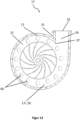
- Figure 13 shows a longitudinal section through a housing 10 according to the invention of an alternative embodiment with an inside view of the rear part 17 with inserted fan wheel 5.
- Figure 14 shows a cross section through the housing 10 of the alternative embodiment of Fig. 13 .
- Figure 15 shows schematically a cross section through the housing wall 11 of an inner side of the front part 16i or an inner side of the rear part 17i of the alternative embodiment of Fig. 13 / 14 .
- the countersunk holes 60 can preferably be arranged on the flow channel 50 and/or on the outlet channel 34.
- the countersunk holes 60 can be arranged in or on the inner side 16i, 17i in the area of the flow channel 50 and/or the outlet channel 34.
- a structure can be introduced into the inner surface 16i, 17i through the countersunk holes 60, which can have a positive effect on the rotational sound.
- the countersunk holes 60 can be made on the inside of the rear part 17i ( Fig. 13 ) and/or on the inside of the front part 16i (not shown).
- the countersunk holes 60 can be formed, for example, by a recess in the inside of the rear part 17i and/or in the inside of the front part 16i.
- the countersunk holes 60 have a depth 60T (see Fig. 15 ).
- the countersunk holes 60 are arranged on at least one of the inner sides of the housing 16i, 17i, preferably on both inner sides 16i, 17i.
- the countersunk holes 60 are arranged and designed such that the otherwise substantially smooth surface of the inner sides 16i, 17i has sections that are recessed.
- the counterbores 60 can be evenly distributed. In some embodiments, the counterbores 60 can only be arranged in specific areas or sections (not shown). The counterbores 60 can also be randomly distributed over the inner sides 16i and/or 17i.
- the countersunk holes 60 can have a depth 60T of 0.5 mm to 2.5 mm.
- the countersunk holes 60 can preferably have a depth 60T of 1 mm to 2 mm.
- the countersunk holes 60 have a depth 60T of 1.4 mm.
- the degree of the depression is selected such that the tonality is reduced.
- the degree of the depression is selected such that the total sound pressure is reduced or remains the same.
- the degree of the depression is selected such that the characteristics can be improved.
- the countersunk holes 60 can all be of the same depth or vary in their depth 60T. In some embodiments, the countersunk holes 60 can have different depths 60T in specific areas of the inner sides 16i, 17i.
- the recess of the countersunk holes 60 can be straight (see Fig. 15 ). In some embodiments, the recess of the counterbores 60 may be tapered and/or flared (not shown). The counterbores 60 may have a random shape in some embodiments.
- the counterbores 60 can have any suitable geometry. In a preferred embodiment, the counterbores 60 can be round and/or oval. The counterbores 60 have a diameter 60D (see Fig. 15 ). The countersunk holes 60 can have a diameter 60D of 1 mm to 7 mm. Preferably, the countersunk holes 60 have a diameter 60D of 2 mm to 5 mm. For example, the countersunk holes 60 can have a diameter 60D of 4 mm.
- the inside of the rear part 17i and/or the inside of the front part 16i can have up to 100 or more countersunk holes 60.
- the number of countersunk holes 60 can be in a range from 1 to 100, preferably in a range from 1 to 50, particularly preferably in a range from 4 to 20.
- the inside of the rear part 17i and/or the inside of the front part 16i can each have 12 countersunk holes 60.
- the number of countersunk holes 60 is selected such that the tonality decreases.
- the number of countersunk holes 60 is selected such that the total sound pressure is reduced or remains the same.
- the countersunk holes 60 can alternatively or additionally be arranged in the inner peripheral wall of the housing.
- the countersunk holes in the housing have the effect of significantly reducing the noise emission.
Landscapes
- Engineering & Computer Science (AREA)
- Mechanical Engineering (AREA)
- General Engineering & Computer Science (AREA)
- Health & Medical Sciences (AREA)
- Emergency Medicine (AREA)
- Pulmonology (AREA)
- Anesthesiology (AREA)
- Biomedical Technology (AREA)
- Heart & Thoracic Surgery (AREA)
- Hematology (AREA)
- Life Sciences & Earth Sciences (AREA)
- Animal Behavior & Ethology (AREA)
- General Health & Medical Sciences (AREA)
- Public Health (AREA)
- Veterinary Medicine (AREA)
- Structures Of Non-Positive Displacement Pumps (AREA)
- Respiratory Apparatuses And Protective Means (AREA)
Description
- Beatmungs- und Atemtherapiegeräte zur Beatmung bzw. Atmungsunterstützung oder zur Hustenunterstützung weisen für die Durchführung einer Atemtherapie eine Lüftereinrichtung zum Erzeugen einer Atemluftströmung auf. Im Gehäuse der Lüftereinrichtung ist üblicherweise wenigstens ein drehbar gelagertes Lüfterrad mit einer Mehrzahl von Schaufelelementen angeordnet.
- Damit die Behandlung bzw. Therapie nicht als störend empfunden wird, sollten die Betriebsgeräusche der Lüftereinrichtung möglichst gering sein. Für einen effizienten Druckaufbau und eine gezielte Atemtherapie ist es zudem entscheidend, dass hohe Drehzahlen erreicht werden und möglichst zügige und kurzfristige Drehzahlanpassungen des Lüfterrades erfolgen können.
AU 2020 233 744 A1 WO 2013/072846 A1 ,WO 2011/062633 A1 undUS 2012/180792 A1 offenbaren Atemtherapiegeräte mit verringerter Schallemission.WO 2020/070349 A1 offenbart ein Gebläse zur Belüftung mit flexiblen Schaufelelementen. - Durch Wirbelablösungen und turbulente An- und Abströmungen innerhalb des Gehäuses entstehen Strömungsgeräusche. Diese Strömungsgeräusche setzen sich aus einem breitbandigen Rauschanteil und überlagerten Tönen zusammen. Der Drehklang wird insbesondere durch die Laufradschaufeln verursacht, wenn das Fluid aus den Schaufelkanälen auf die Gehäusezunge des Gehäuses strömt. Aufgabe der vorliegenden Erfindung ist, ein Atemtherapiegerät zur Verfügung zu stellen, welches die zuvor genannten Anforderungen möglichst vorteilhaft erfüllen kann.
- Diese Aufgabe wird gelöst mit einem Atemtherapiegerät des Anspruchs 1 sowie mit einer Lüftereinrichtung gemäß Anspruch 14.
- Weiterbildungen und vorteilhafte Ausgestaltungen sind Gegenstand der Unteransprüche. Weitere Vorteile und Merkmale ergeben sich aus der allgemeinen Beschreibung und der Beschreibung der Ausführungsbeispiele.
- Das erfindungsgemäße Atemtherapiegerät umfasst wenigstens eine Lüftereinrichtung zum Erzeugen einer Atemluftströmung für die Durchführung einer Atemtherapie, wobei die Lüftereinrichtung ein Gehäuse und wenigstens ein in dem Gehäuse drehbar gelagertes Lüfterrad umfasst, wobei die Atemluft durch einen innerhalb des Gehäuses ausgebildeten Kanal transportiert wird, wobei der Kanal einen Einlasskanal, mindestens einen Strömungskanal und mindestens einen Auslasskanal umfasst, die kommunizierend miteinander in Verbindung stehen, wobei das Gehäuse wenigstens ein Strukturelement aufweist, das die Schallemission verringert. Erfindungsgemäß ist das Strukturelement als mindestens eine Trennwand ausgebildet ist, wobei die Trennwand zumindest abschnittsweise im Lumen des Strömungskanals und im Lumen des Auslasskanals angeordnet ist, wobei die Trennwand den Strömungskanal und den Auslasskanal zumindest abschnittsweise zumindest teilweise in mindestens zwei Kanäle unterteilt.
- In manchen Ausführungsformen ist das Atemtherapiegerät dadurch gekennzeichnet, dass das Gehäuse mindestens eine Innenseite 16i, 17i umfasst und der Kanal ein Lumen umfasst, wobei das Lumen des Kanals von der Innenseite 16i und/oder 17i umschlossen ist.
- In manchen Ausführungsformen ist das Atemtherapiegerät dadurch gekennzeichnet, dass das mindestens eine Strukturelement im Lumen des Kanals angeordnet ist.
- In manchen Ausführungsformen ist das Atemtherapiegerät dadurch gekennzeichnet, dass das mindestens eine Strukturelement in und/oder an der Innenseite 16i, 17i angeordnet ist.
- In manchen Ausführungsformen ist das Atemtherapiegerät dadurch gekennzeichnet, dass der Kanal einen Strömungsweg mit einer Strömungsrichtung ausbildet.
- In manchen Ausführungsformen ist das Atemtherapiegerät dadurch gekennzeichnet, dass die Strömungsrichtung vom Einlasskanal zum Strömungskanal zum Auslasskanal verläuft.
- In manchen Ausführungsformen ist das Atemtherapiegerät dadurch gekennzeichnet, dass das Strukturelement zusätzlich als mindestens eine Senkbohrung ausgebildet ist.
- In manchen Ausführungsformen ist das Atemtherapiegerät dadurch gekennzeichnet, dass die Trennwand derart im Kanal angeordnet ist, dass eine zweite Zunge im Strömungskanal oder im Auslasskanal ausgebildet ist.
- In manchen Ausführungsformen ist das Atemtherapiegerät dadurch gekennzeichnet, dass die mindestens eine Senkbohrung in der Innenseite 16i und/oder 17i im Bereich des Strömungskanals und/oder des Auslasskanals angeordnet ist.
- In manchen Ausführungsformen ist das Atemtherapiegerät dadurch gekennzeichnet, dass die Senkbohrungen durch eine Vertiefung in der Innenseite 16i und/oder 17i ausgebildet sind.
- In manchen Ausführungsformen ist das Atemtherapiegerät dadurch gekennzeichnet, dass die Senkbohrungen eine Tiefe von 0,5 mm bis 2,5 mm, bevorzugt von 1 mm bis 2 mm, besonders bevorzugt von 1,4 mm aufweisen.
- In manchen Ausführungsformen ist das Atemtherapiegerät dadurch gekennzeichnet, dass die Senkbohrungen rund und/oder oval ausgebildet sind.
- In manchen Ausführungsformen ist das Atemtherapiegerät dadurch gekennzeichnet, dass die Senkbohrungen einen Durchmesser von 1 mm bis 7 mm aufweisen, bevorzugt von 2 mm bis 5 mm, besonders bevorzugt von 4 mm aufweisen.
- In manchen Ausführungsformen ist das Atemtherapiegerät dadurch gekennzeichnet, dass die Innenseiten 16i und/oder 17i 1 bis 100 Senkbohrungen aufweisen, bevorzugt bis 1 bis 50, besonders bevorzugt bis 4 bis 20.
- Die erfindungsgemäße Lüftereinrichtung ist für ein Atemtherapiegerät vorgesehen, wie es vorzugsweise zuvor beschrieben wurde. Die Lüftereinrichtung umfasst ein Gehäuse und wenigstens ein in dem Gehäuse drehbar gelagertes Lüfterrad. Dabei ist die Lüftereinrichtung wie zuvor für das erfindungsgemäße Atemtherapiegerät beschrieben ausgebildet.
- In den Figuren sind Ausführungsbeispiele des erfindungsgemäßen Atemtherapiegeräts dargestellt. Es zeigen:
-
Fig. 1 eine schematische Darstellung eines erfindungsgemäßen Atemtherapiegerätes in einer perspektivischen Ansicht -
Fig. 2 eine schematische Außenansicht eines erfindungsgemäßen Gehäuses von vorne -
Fig. 3 eine schematische Außenansicht eines erfindungsgemäßen Gehäuses von hinten -
Fig. 4 einen Längsschnitt durch ein erfindungsgemäßes Gehäuse eines Ausführungsbeispiels mit einer Innenansicht des Hinterteils, wobeiFig. 4A eine Ansicht mit eingesetztem Lüfterrad und ohne Trennwand zeigt undFig. 4B eine Ansicht ohne eingesetztes Lüfterrad und mit einer erfindungsgemäßen Trennwand zeigt. -
Fig. 5 einen Längsschnitt durch das Gehäuse ausFig.4 mit einer Innenansicht des Vorderteils -
Fig. 6 einen vergrößerten Ausschnitt ausFig. 4B -
Fig. 7 eine schematische Außenansicht des Gehäuses ausFig. 4-6 von der Seite mit Blickrichtung in einen Druckstutzen hinein -
Fig. 8 einen Querschnitt durch das Gehäuse ausFig. 4-7 -
Fig. 9 einen Längsschnitt durch ein erfindungsgemäßes Gehäuse eines weiteren Ausführungsbeispiels mit einer Innenansicht des Hinterteils mit eingesetztem Lüfterrad -
Fig. 10 einen Längsschnitt durch das Gehäuse des weiteren Ausführungsbeispiels mit einer Innenansicht des Vorderteils -
Fig. 11 eine schematische Außenansicht des Gehäuses entsprechend des weiteren Ausführungsbeispiels ausFig. 9-10 von der Seite mit Blickrichtung in einen Druckstutzen hineinFig. 12 einen Querschnitt durch das Gehäuse des weiteren Ausführungsbeispiels ausFig.9-11 -
Fig. 13 einen Längsschnitt durch ein erfindungsgemäßes Gehäuse eines alternativen Ausführungsbeispiels mit einer Innenansicht des Hinterteils mit eingesetztem LüfterradFig. 14 einen Querschnitt durch das Gehäuse des alternativen Ausführungsbeispiels ausFig. 13 . -
Figur 15 schematisch einen Querschnitt durch die Gehäusewand einer Innenseite des Vorderteils bzw. einer Innenseite des Hinterteils des alternativen Ausführungsbeispiels ausFig. 13 /14 . - In den nachfolgenden Ausführungsbeispielen ist ein erfindungsgemäßes Atemtherapiegerät 70 gezeigt. Weitere Merkmale und Vorteile der vorliegenden Erfindung werden in den nachfolgenden Beschreibungen von Ausführungsbeispielen anhand der Figuren deutlich. Die Erfindung ist nicht auf die dargestellten Ausführungsbeispiele beschränkt.
-
Figur 1 zeigt eine schematische Darstellung eines erfindungsgemäßen Atemtherapiegerätes 70 in einer perspektivischen Ansicht. - Das erfindungsgemäße Atemtherapiegerät 70 ist beispielsweise ein Beatmungsgerät für klinische oder Heimanwendungen, ein Notfallbeatmungsgerät, ein Atemtherapiegerät oder ein Hustentherapiegerät. Das Atemtherapiegerät 70 ist mit einer hier nicht sichtbar im Geräteinneren untergebrachten erfindungsgemäßen Lüftereinrichtung 1 ausgestattet, mit der eine Atemluftströmung für eine Atemtherapie erzeugt wird.
- Die Lüftereinrichtung 1 hat ein Gehäuse 10, in dem ein Lüfterrad 5 angeordnet ist. Das Lüfterrad 5 ist in dem Gehäuse 10 drehbar gelagert angeordnet. Das Lüfterrad 5 umfasst mehrere Schaufelelemente 6. Zum Drehen des Lüfterrades 5 weist die Lüftereinrichtung 1 einen elektrischen Antrieb auf, der Rotationsenergie auf das Lüfterrad 5 überträgt. Durch die Rotationsbewegung entsteht am Lüfterrad 5 eine Druck- und eine Unterdruckseite, wodurch die Atemluftströmung entsteht. Atemluft umfasst im Sinne der Erfindung jegliches Fluid, Atemgas und/oder Gasgemisch, welches sich zur Beatmung, Atmung und/oder Atemtherapie eignet und eingesetzt werden kann. Insbesondere kann die Atemluft auch Sauerstoff sein oder mit Sauerstoff angereicherte Luft sein.
- Lüftereinrichtungen 1, die in Atemtherapiegeräten 70 eingesetzt werden, sind üblicherweise Radialgebläse. Bei Radialgebläsen tritt ein Fluid, beispielsweise Atemluft, in Achsrichtung in die Lüftereinrichtung 1 ein und tritt senkrecht zur Achsrichtung wieder aus der Lüftereinrichtung 1 heraus. Die Lüftereinrichtung 1 kann neben Atemluft auch jedes andere Gasgemisch transportieren, das für eine Atemtherapie benötigt wird.
- Die Lüftereinrichtung 1 wird über eine nicht sichtbar im Geräteinneren angeordnete Steuereinrichtung 74 angesteuert. Beispielsweise stellt die Steuereinrichtung 74 in Abhängigkeit der Therapievorgaben eine bestimmte Drehzahl des Lüfterrades 5 ein bzw. regelt die Lüfterdrehzahl auf einen Sollwert.
- Das Atemtherapiegerät 70 ist hier mit einer Bedieneinrichtung 71 und mit einer Anzeigeeinrichtung 72 ausgestattet. Dabei erfolgt hier beispielsweise ein Teil der Bedienung über eine berührungsempfindliche Oberfläche der Anzeigeeinrichtung 72.
- Das Atemtherapiegerät 70 weist eine Schnittstelle 76 zum Koppeln eines Schlauchsystems 73 zur Beatmung bzw. Hustenunterstützung auf. Die mittels der Lüftereinrichtung 1 erzeugte Atemluftströmung wird über das Schlauchsystem 73 dem nicht gezeigten Patienten zugeführt. An das Schlauchsystem 73 kann ein hier nicht näher dargestelltes Patienteninterface 75 wie beispielsweise eine Atemmaske angeschlossen werden.
- Die
Figuren 2 bis 14 zeigen verschiedene Ausführungsbeispiele der erfindungsgemäßen Lüftereinrichtung 1, wobei das Gehäuse 10 der Lüftereinrichtung 1 in unterschiedlichen Ausführungsbeispielen und in unterschiedlichen Ansichten exemplarisch dargestellt ist. Die Erfindung ist nicht auf die dargestellten Ausführungsbeispiele beschränkt. - Das Gehäuse 10 der Lüftereinrichtung 1 ist in der Regel spiralförmig. Die Lüftereinrichtung 1 umfasst einen Saugstutzen 20 und einen Druckstutzen 30. Über den Saugstutzen 20 kann das Fluid, beispielsweise Atemluft angesaugt werden. Über den Druckstutzen 30 kann das Fluid abgegeben werden. Der Saugstutzen weist eine Mittelachse 13 auf. Durch den Saugstutzen 20 tritt Atemluft in Achsrichtung in die Lüftereinrichtung 1 ein. Durch den Druckstutzen 30 tritt die Atemluft senkrecht zur Achsrichtung wieder aus der Lüftereinrichtung 1 heraus.
- Das spiralförmige Gehäuse 10 sorgt dafür, dass die Atemluft im Gehäuse 10 gesammelt und zum Druckstutzen 30 geleitet wird, wo sie aus dem Gehäuse 10 austritt. Dabei wird verhindert, dass kreisende Austrittsströmungen entstehen, die zu Verlusten führen. Gleichzeitig wird durch das Spiralgehäuse 10 ein Teil der Geschwindigkeitsenergie der Atemluft in Druckenergie umgewandelt.
- Das spiralförmige Gehäuse 10 hat eine Gehäusewand 11 und umfasst ein Vorderteil 16 und ein Hinterteil 17. Das Vorderteil 16 ist per definitionem das Element, das den Saugstutzen 20 umfasst. Das Hinterteil 17 ist per definitionem das Element, das eine Öffnung 40 umfasst, durch die eine Welle eines Elektromotors mit dem Lüfterrad 5 verbunden werden kann (nicht gezeigt).
- Vorderteil 16 und Hinterteil 17 können einstückig oder zweistückig gefertigt sein. Bevorzugt werden Vorderteil 16 und Hinterteil 17 zweistückig gefertigt. Eine zweistückige Fertigung erleichtert die Fertigung und Montage. Die Lüftereinrichtung 1 befindet sich in einem Anwendungszustand, wenn Vorderteil 16 und Hinterteil 17 miteinander verbunden sind und ein nicht gezeigtes Lüfterrad 5 derart umschließen, dass das Lüfterrad 5 drehbar gelagert ist.
- Vorderteil 16 und Hinterteil 17 können beispielsweise miteinander verklebt, verschweißt, verschraubt, verklemmt, verpresst oder ähnliches werden. Vorderteil 16 und/oder Hinterteil 17 können beispielsweise auch mit einem Hinterschnitt miteinander verbunden werden. Auf diese Weise können Vorderteil 16 und Hinterteil 17 miteinander verbunden werden. Die Verbindung kann reversibel oder irreversibel sein. Durch die Verbindung bei einer zweistückigen Fertigung kann eine Verbindungsfuge 18 entstehen. Die Verbindungsfuge 18 ist bevorzugt derart gering ausgeprägt, dass sie keine Beeinträchtigung des Strömungsweges verursacht.
- Das Gehäuse 10 kann aus unterschiedlichen Materialien hergestellt werden. Die Wahl des Materials kann Auswirkungen auf die Formtreue des Gehäuses 10 und die Rauigkeit der Oberflächen haben. Das Gehäuse 10 kann beispielsweise aus Kunststoff und/oder Metall gefertigt sein. Beispielsweise ist das Gehäuse 10 aus einem spritzbaren Kunststoff gefertigt. Bevorzugt ist das Gehäuse 10 aus Polycarbonat und/oder Polyamid gefertigt. Beispielsweise ist das Gehäuse 10 aus Polyamid PA12 hergestellt.
-
Figur 2 zeigt eine schematische Außenansicht eines erfindungsgemäßen Gehäuses 10 von vorne.Fig. 2 zeigt das Vorderteil 16 des Gehäuses 10. Das Vorderteil 16 umfasst eine Außenseite 16a. Die Außenseite 16a weist in der Regel eine im Wesentlichen glatte Oberfläche auf. - Das Vorderteil 16 umfasst den Saugstutzen 20. Der Saugstutzen 20 hat eine Saugstutzenwand 21 mit einer Saugstutzen-Außenseite 20a und einer Saugstutzen-Innenseite 20i. Der Saugstutzen 20 bildet einen Einlasskanal 24 und umfasst eine Einlassöffnung 22. Der Saugstutzen 20 kann als länglicher Hohlkörper ausgebildet sein, in dessen Lumen der Einlasskanal 24 verläuft. Die Saugstutzen-Innenseite 20i umfasst das Lumen des Saugstutzens 20, in dem der Einlasskanal 24 verläuft.
- Der Durchmesser des Saugstutzens 20 kann jegliche geeignete Geometrie aufweisen. In der Regel ist der Durchmesser des Saugstutzens 20 rund ausgebildet, beispielsweise kreisrund. Der Saugstutzen 20 ragt üblicherweise aus der Außenkontur des Gehäuses 10 hervor und tritt aus der Ebene der Außenseite 16a heraus (siehe bspw.
Fig. 8 ). - Durch den Einlasskanal 24 im Saugstutzen 20 kann ein Fluid, beispielsweise ein Atemgas oder Gasgemisch, in das Gehäuse 10 eintreten. Bevorzugt kann Atemluft über den Einlasskanal 24 und den Saugstutzen 20 in das Gehäuse 10 eintreten. Über den Saugstutzen 20 kann beispielsweise Umgebungsluft angesaugt werden. In manchen Ausführungsformen kann der Saugstutzen 20 mit einem hier nicht gezeigten Schlauch verbunden sein, über den ein definiertes Gas und/oder Gasgemisch in den Einlasskanal 24 eingeleitet werden kann.
- Um eine Schlauchverbindung zum Saugstutzen 20 zu ermöglichen, kann der Saugstutzen 20 einen Saugstutzen-Flansch 29 umfassen. Der Saugstutzen-Flansch 29 kann als ringförmige Verbreiterung am Ende des Saugstutzens ausgebildet sein (nicht gezeigt).
- Die Saugstutzen-Innenseite 20i kann beispielsweise glatt ausgebildet sein. In manchen Ausführungsformen ist es auch denkbar, dass die Saugstutzen-Innenseite 20i strukturiert ausgebildet ist und beispielsweise Rippen, Furchen, Kanäle oder dergleichen aufweist, um die Strömungseigenschaften des Fluids zu optimieren (nicht gezeigt).
- Um den Saugstutzen 20 herum kann mindestens eine, bevorzugt mehrere Stützrippen 25 angeordnet sein. Die Stützrippen 25 können beispielsweise zumindest abschnittsweise auf der Saugstutzen-Außenseite 20a angeordnet sein. Beispielsweise können die Stützrippen 25 an der Saugstutzen-Außenseite 20a und an der Außenseite des Gehäusevorderteils 16a angeordnet sein und diese miteinander stützend verbinden. Die Stützrippen 25 sind eingerichtet und ausgebildet, dem Saugstutzen 20 Stabilität zu verleihen.
- Das Gehäuse 10 umfasst den Druckstutzen 30. Der Druckstutzen 30 weist eine Auslassöffnung 32 auf. Der Auslassöffnung 32 stellt eine druckseitige Ausströmöffnung aus dem Gehäuse 10 dar. Durch den Druckstutzen 30 kann ein Fluid, beispielsweise ein Atemgas oder Gasgemisch, aus dem Gehäuse 10 austreten. Bevorzugt kann Atemluft durch den Druckstutzen 30 austreten.
- Der Druckstutzen 30 weist eine Druckstutzenwand 31 mit einer Druckstutzen-Außenseite 30a und einer Druckstutzen-Innenseite 30i (siehe bspw.
Fig. 4 ) auf und ist in der Regel zumindest teilweise als länglicher Hohlkörper ausgebildet. Der Hohlkörper des Druckstutzens 30 bildet einen Auslasskanal 34 (siehe bspw.Fig. 4 ). Der Durchmesser des Druckstutzens 30 kann jegliche geeignete Geometrie aufweisen. In der Regel ist der Durchmesser des Druckstutzens 30 rund ausgebildet, beispielsweise kreisrund. - Der Druckstutzen 30 kann mit einem hier nicht gezeigten Schlauch oder Schlauchsystem 73 verbunden sein, über den die Atemluft aus dem Gehäuse 10 abgeführt wird. Über das Schlauchsystem 73 kann die Atemluft dem nicht dargestellten Patienten zugeführt werden. Um eine Schlauchverbindung zum Druckstutzen 30 zu ermöglichen, kann der Druckstutzen 30 einen Druckstutzen-Flansch 39 umfassen. Der Druckstutzen-Flansch 39 kann als ringförmige Verbreiterung am Ende des Druckstutzens ausgebildet sein. Der Druckstutzen-Flansch 39 kann beispielsweise an die Druckstutzenwand 31 angeformt sein.
-
Figur 3 eine schematische Außenansicht eines erfindungsgemäßen Gehäuses 10 von hinten.Fig. 3 zeigt das Hinterteil 17 des Gehäuses 10. Das Hinterteil 17 umfasst eine Außenseite 17a. Die Außenseite 17a weist in der Regel eine im Wesentlichen glatte Oberfläche auf. - Das Hinterteil 17 umfasst mindestens eine Öffnung 40. Durch die Öffnung 40 kann eine Welle eines Elektromotors hindurchführen, die im Inneren des Gehäuses 10 mit einem Lüfterrad 5 verbunden werden kann, um dieses anzutreiben (nicht gezeigt). Die Öffnung 40 kann beispielsweise rund ausgebildet sein. In alternativen Ausführungsformen kann die Öffnung 40 auch jegliche andere geeignete Geometrie aufweisen.
- Gehäuse 10 und Elektromotor können beispielsweise miteinander verschraubt werden. In einer bevorzugten Ausführungsform kann das Gehäuse 10 auf den Elektromotor gespritzt werden.
- Das Hinterteil 17 kann ein oder mehrere Bohrungen 42 aufweisen. Beispielsweise kann das Hinterteil 17 vier Bohrungen 42 aufweisen. Die Bohrungen 42 sind bevorzugt radial um die Öffnung 40 herum angeordnet. Über die Bohrungen 42 kann das Gehäuse 10 mit dem Elektromotor verschraubt werden. Radial um die Öffnung 40 herum können zur Versteifung ein oder mehrere Elemente 41 angeordnet sein.
-
Figur 4 zeigt einen Längsschnitt durch ein erfindungsgemäßes Gehäuse 10 eines Ausführungsbeispiels mit einer Innenansicht des Hinterteils 17, wobeiFig. 4A eine Ansicht mit eingesetztem Lüfterrad 5 und ohne Trennwand 33 zeigt undFig. 4B eine Ansicht ohne eingesetztes Lüfterrad 5 und mit einer erfindungsgemäßen Trennwand 33 zeigt.Figur 5 zeigt einen Längsschnitt durch das Gehäuse 10 ausFig. 4 mit einer Innenansicht des Vorderteils 16. - Aus
Fig. 4B wird ersichtlich, dass das Hinterteil 17 eine Aufnahmeeinrichtung 43 umfassen kann, die das Lüfterrad 5 aufnehmen kann. InFig. 4A ist beispielhaft dargestellt, wie das Lüfterrad 5 zur Herstellung eines Anwendungszustandes positioniert sein kann. Die Lüftereinrichtung 1 befindet sich in einem Anwendungszustand, wenn das Lüfterrad 5 in die Aufnahmeeinrichtung 43 eingesetzt ist und Vorderteil 16 und Hinterteil 17 miteinander verbunden sind. Dabei ist das Lüfterrad 5 derart eingesetzt, dass das Lüfterrad 5 drehbar gelagert ist. - In der Regel ist innerhalb der Aufnahmeeinrichtung 43 die Öffnung 40 angeordnet, durch die die Welle eines Elektromotors hindurchführt, der das Lüfterrad 5 antreibt. Die Mittelachse 13 kann in der Mitte der Öffnung 40 liegen.
- Das Hinterteil 17 umfasst eine Innenseite 17i (
Fig. 4 ). Die Oberfläche der Innenseite 17i kann glatt oder zumindest teilweise strukturiert ausgebildet sein. In der Regel weist die Innenseite 17i eine im Wesentlichen glatte Oberfläche auf. - Das Vorderteil 16 umfasst eine Innenseite 16i (
Fig. 5 ). Die Oberfläche der Innenseite 16i kann glatt oder zumindest teilweise strukturiert ausgebildet sein. In der Regel weist die Innenseite 16i eine im Wesentlichen glatte Oberfläche auf. - In einem Anwendungszustand, also wenn Vorderteil 16 und Hinterteil 17 miteinander verbunden sind, ist im Inneren des Gehäuses 10 ein Kanal 12 eingerichtet und ausgebildet. Durch den Kanal 12 kann das Fluid, beispielsweise Atemluft strömen. Der Kanal 12 ist als Hohlkörper ausgebildet. Der Kanal 12 hat ein Lumen. Das Lumen des Kanals 12 wird zumindest teilweise von den Innenseiten 16i und/oder 17i umgeben.
- Die Innenseiten 16i, 17i können gewölbt sein, um den Kanal 12 auszubilden. Beispielsweise können die Innenseiten 16i, 17i derart gewölbt sein, dass der Kanal einen im Wesentlichen runden Kanal 12 ausbilden. Beispielsweise weist der Kanal 12 einen im Wesentlichen kreisrunden Querschnitt auf (siehe beispielsweise
Fig. 8 ). - Die Druckstutzen-Innenseite 30i ist ein Teilabschnitt der Innenseiten 16i und 17i. Die Innenseiten 16i und 17i, die das Lumen des Druckstutzens 30 umschließen, werden hierin auch als Druckstutzen-Innenseite 30i bezeichnet.
- Der Kanal 12 kann einen Einlasskanal 24 (siehe
Fig. 2 ), einen Strömungskanal 50 und einen Auslasskanal 34 umfassen (sieheFig. 4A ). Einlasskanal 24, Strömungskanal 50 und Auslasskanal 34 sind kommunizierende Kanäle. Einlasskanal 24, Strömungskanal 50 und Auslasskanal 34 stehen fluidisch miteinander in Verbindung. Einlasskanal 24, Strömungskanal 50 und Auslasskanal 34 bilden einen Strömungsweg mit einer Strömungsrichtung 80 aus (sieheFig. 4A ). Beispielsweise stehen Einlasskanal 24, Strömungskanal 50 und Auslasskanal 34 pneumatisch miteinander in Verbindung. Ein Fluid, beispielsweise Atemluft, kann in den Einlasskanal 24 strömen und von dort über das Lüfterrad 5 in den Strömungskanal 50 und vom Strömungskanal 50 in den Auslasskanal 34 strömen. Die Strömungsrichtung 80 verläuft in der Regel vom Einlasskanal 24 über den Strömungskanal 50 in den Auslasskanal 34. - Bei einer zweistückigen Fertigung der Lüftereinrichtung 1 kann der Strömungskanal 50 und/oder der Auslasskanal 34 von der Innenseite des Vorderteils 16i und von der Innenseite des Hinterteils 17i umschlossen sein.
- In einem Anwendungszustand umschließen die Innenseiten 16i, 17i zumindest teilweise zumindest abschnittsweise den Strömungskanal 50. In einem Anwendungszustand umschließt die Druckstutzen-Innenseite 30i zumindest teilweise zumindest abschnittsweise den Auslasskanal 34. Der Auslasskanal 34 durchzieht den Druckstutzen 30 der Länge nach.
- Die Druckstutzen-Innenseite 30i kann beispielsweise glatt ausgebildet sein. In manchen Ausführungsformen ist es auch denkbar, dass die Druckstutzen-Innenseite 30i strukturiert ausgebildet ist und beispielsweise Rippen, Furchen, Kanäle oder dergleichen aufweist, um die Strömungseigenschaften des Fluids zu optimieren (nicht gezeigt).
- Die Innenseiten 16i,17i und/oder die Druckstutzen-Innenseite 30i und/oder die Saugstutzen-Innenseite 20i können in manchen Ausführungsformen im Bereich des Kanals 12 eine im Wesentlichen glatte Oberfläche aufweisen. Die Oberfläche kann auch eine materialbedingte Rauigkeit besitzen. Die Beschaffenheit der Oberfläche kann den Druckverlauf und den Drehklang beeinflussen.
- Der Strömungskanal 50 ist in einem Anwendungszustand von der Gehäusewand 11 zumindest teilweise umgeben. Der Strömungskanal 50 verläuft zumindest abschnittsweise kreisförmig. Der Strömungskanal 50 steht mit dem Einlasskanal 24 und dem Auslasskanal 34 in Verbindung.
- Über die Einlassöffnung 22 und den Einlasskanal 24 tritt Atemluft in Achsrichtung in die Lüftereinrichtung 1 ein. Der Einlasskanal 24 verläuft beispielsweise zumindest abschnittsweise gerade. Von der Einlassöffnung 22 gelangt die Atemluft über den Einlasskanal 24 in das Lüfterrad 5, das die Atemluft über eine Rotationsbewegung in den Strömungskanal 50 transportiert. Über den weitestgehend kreisförmigen Strömungskanal 50 wird die Atemluft in radialer Richtung transportiert und gelangt in den Auslasskanal 34. Über den Auslasskanal 34 und die Auslassöffnung 32 tritt Atemluft senkrecht zur Achsrichtung aus der Lüftereinrichtung 1 heraus. Dadurch ergibt sich eine spiralförmige Strömungsrichtung 80.
- Dort, wo im Inneren des Gehäuses 10 die Gehäusewand 11 und die Druckstutzenwand 31 aufeinandertreffen, ist eine Gehäusezunge 37 ausgebildet. Definitionsgemäß beginnt der Druckstutzen 30 auf Höhe der Gehäusezunge 37 (siehe
Fig. 4A ). - Die Atemluft strömt auf die Gehäusezunge 37, wodurch ein Drehklang entstehen kann. Auch durch Wirbelablösungen und/oder turbulente An- und/oder Abströmungen können innerhalb der Lüftereinrichtung 1 Strömungsgeräusche entstehen. Ferner entsteht Drehklang durch die Schaufelelemente 6 des Lüfterrades 5, wenn diese die Atemluft verdrängen.
- Die Gehäusezunge 37 bildet eine Hauptquelle des Drehklanges. Die Position der Gehäusezunge 37 und/oder der Abstand zwischen Lüfterrad 5 und Gehäusezunge 37 können hierbei einen Einfluss auf die Lautstärke des Drehklanges haben.
- Erfindungsgemäß weist das Gehäuse 10 wenigstens ein Strukturelement 33, 60 auf, das die Schallemission verringert.
- Der Auslasskanal 34 ist in einem Anwendungszustand von der Druckstutzenwand 31 zumindest teilweise umgeben. Der Auslasskanal 34 verläuft beispielsweise zumindest abschnittsweise gerade.
- Der Auslasskanal 34 hat eine Höhe 34H. Üblicherweise ist der Auslasskanal 34 als ein durchgehender Kanal mit einer Höhe 34H ausgebildet (siehe
Fig. 4A ). - In einer vorteilhaften Ausführungsform kann zumindest der Auslasskanal 34 durch mindestens ein Strukturelement 33 zumindest abschnittsweise in unabhängig voneinander verlaufende Kanäle 35, 36 aufgetrennt sein (siehe
Fig. 4B ). Die Kanäle 35, 36 werden hierin weiter unten ausführlicher beschrieben. In alternativen Ausführungsformen kann der Auslasskanal 34 auch durch mindestens ein Strukturelement 33 in miteinander in Verbindung stehende Kanäle aufgetrennt sein. - In einer erfindungsgemäßen Ausführungsform kann das Gehäuse 10 der Lüftereinrichtung 1 mindestens ein Strukturelement 33 umfassen. Das Strukturelement kann in Form einer Trennwand 33 ausgebildet sein (siehe
Fig. 4B und folgende). - Die mindestens eine Trennwand 33 kann aus demselben Material gefertigt sein, wie die Lüftereinrichtung 1. In manchen Ausführungsformen kann die Trennwand 33 auch aus einem anderen geeigneten Material gefertigt sein. Beispielsweise kann die Trennwand 33 aus Metall oder Kunststoff gefertigt sein. Die Trennwand 33 kann am Vorderteil 16 und/oder am Hinterteil 17 angeformt sein.
- Die Trennwand 33 ist mindestens abschnittsweise im Kanal 12 angeordnet. Die Trennwand 33 kann zumindest abschnittsweise im Auslasskanal 34 angeordnet sein. Alternativ oder ergänzend kann die Trennwand 33 im Strömungskanal 50 angeordnet sein.
- Die Trennwand 33 kann einteilig oder zweigeteilt ausgebildet sein. In manchen Ausführungsformen kann die Trennwand 33 zweigeteilt ausgebildet sein und sowohl am Hinterteil 17 als auch am Vorderteil 16 angeformt sein. In einem Anwendungszustand kann die zweigeteilte Trennwand 33 zu einer den Kanal 12 zumindest teilweise vollständig trennenden Trennwand 33 zusammengefügt werden. In manchen Ausführungsformen kann die Trennwand 33 den Kanal 12 zumindest abschnittsweise nur unvollständig teilen (nicht gezeigt).
- In einer bevorzugten Ausführungsform ist die Trennwand 33 einteilig ausgebildet. In einem Anwendungszustand, also wenn Vorderteil 16 und Hinterteil 17 miteinander verbunden sind, kann die einteilig ausgebildete Trennwand 33 den Kanal 12 zumindest abschnittsweise vollständig teilen. Der Kanal 12 kann durch die Trennwand 33 zumindest abschnittsweise zweigeteilt verlaufen.
- Die Trennwand 33 kann beispielsweise einteilig sein und an dem Hinterteil 17 angeformt sein. In diesem Falle kann das Vorderteil 16 eine nicht gezeigte Aufnahmefuge 44 aufweisen, in die die Trennwand 33 eingefügt werden kann. Alternativ kann eine einteilige Trennwand 33 auch an dem Vorderteil 16 angeformt sein. Sodann kann das Hinterteil 17 eine Aufnahmefuge 44 aufweisen, in die die Trennwand 33 eingefügt werden kann (nicht gezeigt).
- Die Trennwand 33 kann zumindest abschnittsweise den Kanal 12 in Strömungsrichtung 80 durchlaufen. Die Trennwand 33 hat einen Anfang 38 und ein Ende 45. Der Anfang 38 der Trennwand 33 liegt in Bezug zur Strömungsrichtung weiter vorne und das Ende 45 der Trennwand 33 liegt in Bezug zur Strömungsrichtung 80 weiter hinten.
- In manchen Ausführungsformen kann das Ende 45 innerhalb des Gehäuses angeordnet sein (nicht gezeigt). In den hier dargestellten beispielhaften Ausführungsformen kann das Ende 45 direkt auf Höhe der Auslassöffnung 32 angeordnet sein (siehe beispielsweise
Fig. 4B ). - Der Anfang 38 liegt innerhalb des Gehäuses. Der Anfang 38 der Trennwand 33 ist im Kanal 12 angeordnet. Durch den Anfang der Trennwand 33 wird eine zweite Zunge 38 in das Gehäuse 10 eingeführt. Die zweite Zunge 38 ist innerhalb des Gehäuses angeordnet. Die zweite Zunge 38 entsteht am Anfang der Trennwand 33. Der Anfang der Trennwand 33 und somit die zweite Zunge 38 kann gerade, abgerundet und/oder angeschrägt ausgebildet sein.
- Durch die zweite Zunge 38 kann die Amplitude des Drehklangs gemindert werden. Durch die zweite Zunge 38 kann sich der Drehklang auf mehrere Frequenzen aufteilen. Somit kann sich der vom Anwender/Patienten subjektiv wahrgenommene Klang verbessern, da die Tonalität des Drehklangs weniger wird. Die Druckkurve wird durch Einführung einer zweiten Zunge 38 hingegen nicht beeinflusst.
-
Figur 6 zeigt einen vergrößerten Ausschnitt ausFig. 4B . Die Trennwand 33 kann den Kanal 12 zumindest abschnittsweise entlang der Strömungsrichtung 80 teilen. Die Trennwand 33 weist eine Länge 33L auf. Die Länge 33L kann unterschiedlich lang ausgebildet sein. Je nach Länge 33L kann die Trennwand 33 den Strömungskanal 50 und/oder den Auslasskanal 34 zumindest abschnittsweise entlang der Strömungsrichtung 80 teilen. - Die Länge der Trennwand 33L kann derart gewählt sein, dass 5% bis 100% des Auslasskanals 34 durch die Trennwand 33 geteilt wird. Bevorzugt wird 20% bis 100% des Auslasskanals 34 durch die Trennwand 33 geteilt, besonders bevorzugt wird 50% bis 100% des Auslasskanals 34 durch die Trennwand 33 geteilt.
- In einem konkreten Ausführungsbeispiel ist die Länge der Trennwand 33L derart eingerichtet und ausgebildet, dass die Trennwand 33 den Auslasskanal 34 der Länge nach vollständig durchläuft. 100% des Auslasskanals 34 sind durch die Trennwand 33 geteilt (siehe
Fig. 6 ). Die Trennwand 33 kann alternativ oder zusätzlich auch den Strömungskanal 50 zumindest teilweise durchlaufen. - Die Länge der Trennwand 33L kann derart gewählt sein, dass 0% bis 90% des Strömungskanal 50 durch die Trennwand 33 geteilt wird. Bevorzugt wird 5% bis 80% des Strömungskanal 50 durch die Trennwand 33 geteilt.
- Die Trennwand 33 kann sich in dem in
Fig. 6 dargestellten konkreten Ausführungsbeispiel bis auf Höhe der Mittelachse 13 erstrecken. Sodann durchläuft die Trennwand 33 den Auslasskanal 34 sowie zumindest teilweise den Strömungskanal 50. In dem inFig. 6 dargestellten konkreten Ausführungsbeispiel wird 100% des Auslasskanals 34 und zusätzlich ca. 15% des Strömungskanals 50 durch die Trennwand 33 geteilt. - Die Trennwand 33 kann sich in dem in
Fig. 6 dargestellten konkreten Ausführungsbeispiel bis zur Auslassöffnung 32 erstrecken. In manchen Ausführungsformen kann die Trennwand 33 auch kürzer ausgebildet sein und innerhalb des Auslasskanals 34 und/ oder innerhalb des Strömungskanals 50 enden (nicht gezeigt). In alternativen Ausführungsbeispielen kann die Trennwand 33 auch länger (sieheFig.9-10 ) oder kürzer (nicht gezeigt) ausgebildet sein. - Die Trennwand 33 weist eine Breite 33B auf. Die Breite der Trennwand 33B kann ebenso breit sein oder breiter sein als die Gehäusewand 11. In einer bevorzugten Ausführungsform ist die Breite der Trennwand 33B schmaler ausgebildet als die Gehäusewand 11. Die Breite der Trennwand 33B liegt in einem Bereich von 0,1 mm bis 8 mm, bevorzugt in einem Bereich von 0,5 mm bis 5 mm, besonders bevorzugt in einem Bereich von 0,5 mm bis 2 mm. Beispielsweise beträgt die Breite der Trennwand 33B 1 mm. Die Trennwand 33 sollte so dünn wie möglich ausgebildet sein, um den Strömungsquerschnitt der Kanäle möglichst groß zu halten. Die Trennwand 33 sollte dennoch so stark ausgebildet sein, dass sie eine ausreichende Stabilität besitzt.
- Die Trennwand 33 kann den Auslasskanal 34 derart trennen, dass ein innerer Auslasskanal 35 mit einer Höhe 35H und ein äußerer Auslasskanal 36 mit einer Höhe 36H entsteht. Über den äußeren Auslasskanal 36 kann die Atemluft aus dem Gehäuse heraustransportiert werden. Über den inneren Auslasskanal 35 kann die Atemluft aus dem Gehäuse 10 heraustransportiert werden und/oder erneut in den Strömungskanal 50 gelangen. Die Anordnung der Trennwand 33 im Kanal 12 kann einen Einfluss auf das Geschwindigkeitsprofil und/oder auf die Druckschwankungen der Strömung haben.
- Die Trennwand 33 kann mittig im Auslasskanal 34 angeordnet sein. Bei einer mittigen Anordnung ist der Auslasskanal zweigeteilt und die Höhe 35H des inneren Auslasskanals 35 entspricht der Höhe 36H des äußeren Auslasskanals 36 (siehe
Fig. 6 ). - In alternativen Ausführungsformen kann die Höhe 35H des inneren Auslasskanals 35 auch kleiner als die Höhe 36H des äußeren Auslasskanals 36 ausgebildet sein. In manchen Ausführungsformen kann die Höhe 35H des inneren Auslasskanals 35 auch größer als die Höhe 36H des äußeren Auslasskanals 36 ausgebildet sein (nicht gezeigt).
- Die Lage des Laufrades 5 zur Trennwand 33 wird durch die radiale Anordnung der Trennwand innerhalb des Kanals 12 bedingt. Ist die Trennwand 33 radial weiter nach außen angeordnet, vergrößert sich der Abstand zum Laufrad 5. Ist die Trennwand 33 radial weiter nach innen angeordnet, verkleinert sich der Abstand zum Laufrad 5. Ein großer Abstand der Trennwand 33 zum Laufrad 5 kann vorteilhaft sein, da dadurch das Geschwindigkeitsprofil geglättet werden kann und Druckschwankungen an der Zunge 37 verringert werden können.
-
Figur 7 eine schematische Außenansicht des Gehäuses 10 ausFig. 4-6 von der Seite mit Blickrichtung in einen Druckstutzen 30 hinein. - Die Trennwand 33 weist eine Höhe 33H auf. Die Trennwand 33 kann zwischen Vorderteil 16 und Hinterteil 17 durchgehend ausgebildet sein. In dem Falle steht die Trennwand 33 mit der Innenseite des Vorderteils 16i und mit der Innenseite des Hinterteils 17i in Verbindung. So kann die Trennwand 33 den Kanal 12 zumindest abschnittsweise vollständig teilen. Beispielsweise trennt die Trennwand 33 den Auslasskanal 34 vollständig in zwei unabhängig voneinander verlaufende Kanäle 35, 36 (
Fig.7 ). - In manchen Ausführungsformen kann die Höhe der Trennwand 33H auch kleiner ausgebildet sein, als der Durchmesser des Auslasskanals 34. Dann kann die Trennwand 33 nicht durchgehend ausgebildet sein und nur mit der Innenseite des Vorderteils 16i oder nur mit der Innenseite des Hinterteils 17i verbunden sein. So kann die Trennwand 33 den Kanal 12 zumindest abschnittsweise unvollständig teilen (nicht gezeigt).
- Die Trennwand 33 kann entlang der Höhe 33H gerade ausgebildet sein (
Fig. 7 ). In manchen Ausführungsformen kann die Trennwand 33 entlang der Höhe 33H auch konvex und/oder konkav gebogen ausgebildet sein (sieheFig. 12 ). -
Figur 8 zeigt einen Querschnitt durch das Gehäuse 10 ausFig. 4-7 . AusFig. 8 wird ersichtlich, dass der Saugstutzen 20 aus der Außenkontur des Gehäuses 10 hervorragt. Die Saugstutzen-Innenseite 20i umfasst das Lumen des Saugstutzens 20, in dem der Einlasskanal 24 verläuft. Über das Lumen des Saugstutzens 20 tritt ein Fluid, beispielsweise Atemluft, in das Gehäuse 10 ein. Die Strömungsrichtung 80 in das Gehäuse 10 hinein ist mit einem Pfeil gekennzeichnet. Die Strömungsrichtung 80 verläuft vom Einlasskanal 24 des Saugstutzens 20 in das Laufrad 5 und vom Laufrad 5 über den Strömungskanal 50 in den Auslasskanal 34 (hier nicht dargestellt). -
Figur 9 zeigt einen Längsschnitt durch ein erfindungsgemäßes Gehäuse 10 eines weiteren Ausführungsbeispiels mit einer Innenansicht des Hinterteils 17 mit eingesetztem Lüfterrad undFigur 10 zeigt einen Längsschnitt durch das Gehäuse 10 des weiteren Ausführungsbeispiels mit einer Innenansicht des Vorderteils 16. - In dem konkreten Ausführungsbeispiel nach
Fig. 9 /10 ist die Trennwand 33 wesentlich länger ausgebildet als zuvor beschrieben. In diesem konkreten Ausführungsbeispiel ist die Länge der Trennwand 33L derart eingerichtet und ausgebildet, dass die Trennwand 33 den Auslasskanal 34 der Länge nach vollständig durchläuft. Der Auslasskanal 34 wird durch die Trennwand 33 unterteilt in einen inneren Auslasskanal 35 und einen äußeren Auslasskanal 36. Beispielsweise sind 100% des Auslasskanals 34 durch die Trennwand 33 geteilt. - Zusätzlich kann die Trennwand 33 zumindest abschnittsweise auch im Strömungskanal 50 angeordnet sein. Der Strömungskanal 50 kann durch die Trennwand 33 in einen inneren Strömungskanal 52 und einen äußeren Strömungskanal 54 unterteilt sein.
- In diesem Ausführungsbeispiel wird 100% des Auslasskanals 34 und zusätzlich ca. 80 % des Strömungskanals 50 durch die Trennwand 33 geteilt. Somit kann die spiralförmige Strömungsrichtung 80 weitestgehend zweigeteilt verlaufen. Dadurch, dass die Trennwand 33 derart lang ausgebildet ist, dass sie zusätzlich im Strömungskanal 50 angeordnet ist, ist die zweite Zunge 38 weit innerhalb des Gehäuses 10 angeordnet. Die zweite Zunge 38 befindet sich am Beginn der Strömungsrichtung 80. Das bietet den Vorteil, dass eine bessere Strömungsführung in der Spirale gegeben ist und/oder weniger Querbewegungen des Fluids möglich sind.
- In manchen Ausführungsformen kann die Trennwand 33 auch ausschließlich im Strömungskanal 50 angeordnet sein und den Strömungskanal 50 zumindest teilweise teilen (nicht gezeigt).
- Die Trennwand 33 kann in manchen Ausführungsformen immer mittig im Kanal 12 angeordnet sein (nicht gezeigt). Die Anordnung der Trennwand 33 innerhalb des Kanals 12 kann sich mit dem Verlauf der Strömungsrichtung 80 verändern (siehe beispielsweise
Fig. 9 ). In dem hier dargestellten konkreten Ausführungsbeispiel ist die Trennwand 33 derart angeordnet, dass der äußere Strömungskanal 54 in seiner Breite nahezu gleichbleibt, wohingegen der innere Strömungskanal 52 in seiner Breite sukzessive zunimmt. Dementsprechend ist die Trennwand im Auslasskanal nicht mittig angeordnet, sondern radial nach außen verlagert. Somit kann die Höhe des äußeren Auslasskanals 36H kleiner als die Höhe des inneren Auslasskanals 35H ausgebildet sein. -
Figur 11 zeigt eine schematische Außenansicht des Gehäuses 10 entsprechend des weiteren Ausführungsbeispiels ausFig. 9-10 von der Seite mit Blickrichtung in einen Druckstutzen 30 hinein. AusFig. 11 wird ersichtlich, dass die Trennwand 33 im Druckstutzen 30 nicht mittig angeordnet sein muss. Die Trennwand 33 ist in diesem Ausführungsbeispiel radial nach außen angeordnet. Dadurch ist die Höhe des inneren Auslasskanals 35H größer als die Höhe des äußeren Auslasskanals 36H. In alternativen Ausführungsformen kann die Trennwand 33 auch mittig angeordnet sein. Dann kann die Höhe des inneren Auslasskanals 35H gleich der Höhe des äußeren Auslasskanals 36H sein (sieheFig. 7 ). In manchen Ausführungsformen kann die Trennwand 33 auch radial nach innen angeordnet sein. Dann kann die Höhe des inneren Auslasskanals 35H kleiner als die Höhe des äußeren Auslasskanals 36H sein (nicht gezeigt). AusFig. 7 wird zudem ersichtlich, dass die Trennwand 33 im Druckstutzen 30 gerade ausgebildet ist. In manchen Ausführungsformen kann die Trennwand 33 alternativ oder zusätzlich zumindest abschnittsweise auch konvex und/oder konkav gebogen ausgebildet sein (sieheFig. 12 ). -
Figur 12 zeigt einen Querschnitt durch das Gehäuse 10 des weiteren Ausführungsbeispiels ausFig. 9-11 . AusFig. 12 wird ersichtlich, dass die Trennwand 33 auch im Strömungskanal 50 angeordnet ist. Durch die Anordnung der Trennwand 33 im Strömungskanal 50 ist dieser in einen inneren Strömungskanal 52 und einen äußeren Strömungskanal 54 getrennt. In diesem konkreten Ausführungsbeispiel ist die Trennwand 33 nicht mittig im Strömungskanal 50 angeordnet, sondern zunehmend radial nach außen verlagert. Dadurch kann der innere Strömungskanal 52 größer ausgebildet sein als der äußere Strömungskanal 54. In manchen Ausführungsformen kann die Trennwand 33 auch derart im Strömungskanal 50 angeordnet sein, dass innerer Strömungskanal 52 und äußerer Strömungskanal 54 gleich groß ausgebildet sind und/oder derart, dass der innere Strömungskanal 52 kleiner als der äußere Strömungskanal 54 ausgebildet ist (nicht gezeigt). Das Verhältnis der Größe des inneren Strömungskanals 52 und des äußeren Strömungskanals 54 kann im Laufe der Strömungsrichtung 80 gleichbleiben (nicht gezeigt) oder sich zueinander verändern (Fig. 9-12 ). - Aus
Fig. 12 wird darüber hinaus ersichtlich, dass die Trennwand 33 entlang der Höhe 33H gerade und/oder gebogen ausgebildet sein kann. In diesem konkreten Ausführungsbeispiel ist die Trennwand 33 zunächst gebogen ausgebildet (33a) und verändert seine Ausbildung im weiteren Strömungsverlauf derart, dass die Trennwand 33 gerade ausgebildet ist (33b). -
Figur 13 zeigt einen Längsschnitt durch ein erfindungsgemäßes Gehäuse 10 eines alternativen Ausführungsbeispiels mit einer Innenansicht des Hinterteils 17 mit eingesetztem Lüfterrad 5.Figur 14 zeigt einen Querschnitt durch das Gehäuse 10 des alternativen Ausführungsbeispiels ausFig. 13 .Figur 15 zeigt schematisch einen Querschnitt durch die Gehäusewand 11 einer Innenseite des Vorderteils 16i bzw. einer Innenseite des Hinterteils 17i des alternativen Ausführungsbeispiels ausFig. 13 /14 . - In
Fig. 13 bis 15 ist eine weitere erfindungsgemäße Ausführungsform gezeigt, bei der das Gehäuse 10 der Lüftereinrichtung 1 alternativ oder zusätzlich mindestens ein Strukturelement 60 umfassen kann. Das Strukturelement kann in Form mindestens einer Senkbohrung 60 ausgebildet sein. Die eine oder mehrere Senkbohrungen 60 können alternativ oder zusätzlich zu der Trennwand 33 in dem Gehäuse 10 angeordnet sein. - Die Senkbohrungen 60 können bevorzugt am Strömungskanal 50 und/oder am Auslasskanal 34 angeordnet sein. Die Senkbohrungen 60 können in oder an der Innenseite 16i, 17i im Bereich des Strömungskanals 50 und/oder des Auslasskanals 34 angeordnet sein. Durch die Senkbohrungen 60 kann eine Struktur in die innere Oberfläche 16i, 17i eingeführt werden, die sich in Bezug auf den Drehklang positiv auswirken kann.
- Die Senkbohrungen 60 können an der Innenseite des Hinterteils 17i (
Fig. 13 ) und/oder an der Innenseite des Vorderteils 16i (nicht gezeigt) angeordnet sein. Die Senkbohrungen 60 können beispielsweise durch eine Vertiefung in der Innenseite des Hinterteils 17i und/oder in der Innenseite des Vorderteils 16i ausgebildet sein. Die Senkbohrungen 60 haben eine Tiefe 60T (sieheFig. 15 ). Die Senkbohrungen 60 sind wenigstens auf einer der Innenseiten des Gehäuses 16i, 17i angeordnet, bevorzugt auf beiden Innenseiten 16i, 17i. Die Senkbohrungen 60 sind derart eingerichtet und ausgebildet, dass die ansonsten im Wesentlichen glatte Oberfläche der Innenseiten 16i, 17i Abschnitte aufweisen, die vertieft vorliegen. - Die Senkbohrungen 60 können gleichmäßig verteilt sein. In manchen Ausführungsformen können die Senkbohrungen 60 nur in bestimmten Bereichen oder Abschnitten punktuell angeordnet sein (nicht gezeigt). Die Senkbohrungen 60 können auch zufällig verteilt über die Innenseiten 16i und/oder 17 i angeordnet sein.
- Die Senkbohrungen 60 können eine Tiefe 60T von 0,5 mm bis 2,5 mm aufweisen. Bevorzugt können die Senkbohrungen 60 eine Tiefe 60T von 1 mm bis 2 mm aufweisen. Beispielsweise weisen die Senkbohrungen 60 eine Tiefe 60T von 1,4 mm auf. Der Grad der Vertiefung ist derart gewählt, dass die Tonalität verringert wird. Der Grad der Vertiefung ist derart gewählt, dass der Gesamtschalldruck verringert wird oder gleichbleibt. Der Grad der Vertiefung ist derart gewählt, dass die Kennlinien verbessert werden können. Die Senkbohrungen 60 können alle gleich tief ausgebildet sein oder in ihrer Tiefe 60T variieren. Die Senkbohrungen 60 können in manchen Ausführungsformen an speziellen Bereichen der Innenseiten 16i, 17i abweichende Tiefen 60T aufweisen.
- Die Vertiefung der Senkbohrungen 60 kann gerade verlaufen (siehe
Fig. 15 ). In manchen Ausführungsformen kann die Vertiefung der Senkbohrungen 60 sich konisch verengen und/oder aufweiten (nicht gezeigt). Die Senkbohrungen 60 können in manchen Ausführungsformen eine zufällige Form aufweisen. - Die Senkbohrungen 60 können jegliche geeignete Geometrie aufweisen. In einer bevorzugten Ausführungsform können die Senkbohrungen 60 rund und/oder oval ausgebildet sein. Die Senkbohrungen 60 haben einen Durchmesser 60D (siehe
Fig. 15 ). Die Senkbohrungen 60 können einen Durchmesser 60D von 1 mm bis 7 mm aufweisen. Bevorzugt weisen die Senkbohrungen 60 einen Durchmesser 60D von 2 mm bis 5 mm auf. Beispielsweise können die Senkbohrungen 60 einen Durchmesser 60D von 4 mm aufweisen. - Die Innenseite des Hinterteils 17i und/oder die Innenseite des Vorderteils 16i können bis zu 100 oder mehr Senkbohrungen 60 aufweisen. Die Anzahl der Senkbohrungen 60 kann in einem Bereich von 1 bis 100 liegen, bevorzugt in einem Bereich von 1 bis 50, besonders bevorzugt in einem Bereich von 4 bis 20. Beispielsweise können die Innenseite des Hinterteils 17i und/oder die Innenseite des Vorderteils 16i jeweils 12 Senkbohrungen 60 aufweisen. Die Anzahl der Senkbohrungen 60 ist derart gewählt, dass die Tonalität abnimmt. Die Anzahl der Senkbohrungen 60 ist derart gewählt, dass der Gesamtschalldruck verringert wird oder gleichbleibt.
- Aus
Fig. 14 wird ersichtlich, dass die Senkbohrungen 60 in manchen Ausführungsformen alternativ oder zusätzlich auch in der inneren Umfangswandung des Gehäuses angeordnet sein können. Die Senkbohrungen im Gehäuse bewirken, dass die Schallemission wesentlich verringert wird. - Obwohl die vorliegende Erfindung anhand der Ausführungsbeispiele detailliert beschrieben wurde, ist es für den Fachmann selbstverständlich, dass die Erfindung nicht auf diese Ausführungsbeispiele beschränkt ist. Vielmehr sind Abwandlungen in einer Weise möglich, dass einzelne Merkmale weggelassen werden oder andersartige Kombinationen der beschriebenen Einzelmerkmale verwirklicht werden können, sofern der Schutzbereich der beiliegenden Ansprüche nicht verlassen wird. Die vorliegende Offenbarung schließt sämtliche Kombinationen der vorgestellten Einzelmerkmale mit ein.
-
1 Lüftereinrichtung 5 Lüfterrad 6 Schaufelelemente 10 Gehäuse 11 Gehäusewand 12 Kanal 13 Mittelachse 16 Vorderteil 16a Außenseite des Vorderteils 16i Innenseite des Vorderteils 17 Hinterteil 17a Außenseite des Hinterteils 17i Innenseite des Hinterteils 18 Verbindungsfuge 20 Saugstutzen 20a Saugstutzen-Außenseite 20i Saugstutzen-Innenseite 21 Saugstutzenwand 22 Einlassöffnung 24 Einlasskanal 25 Stützrippen 29 Saugstutzen-Flansch 30 Druckstutzen 30a Druckstutzen-Außenseite 30i Druckstutzen-Innenseite 31 Druckstutzenwand 32 Auslassöffnung 33 Trennwand 33B Breite der Trennwand 33H Höhe der Trennwand 33L Länge der Trennwand 34 Auslasskanal 34H Höhe des Auslasskanals 35 Innerer Auslasskanal 35H Höhe des inneren Auslasskanals 36 Äußerer Auslasskanal 36H Höhe des äußeren Auslasskanals 37 Gehäusezunge 38 Zweite Zunge 39 Drucksstutzen-Flansch 40 Öffnung 41 Elemente 42 Bohrung 43 Aufnahmeeinrichtung 44 Aufnahmefuge 45 Ende 50 Strömungskanal 52 Innerer Strömungskanal 54 Äußerer Strömungskanal 60 Senkbohrung 60D Durchmesser der Senkbohrung 60T Tiefe der Senkbohrung 70 Atemtherapiegerät 71 Bedieneinrichtung 72 Anzeigeeinrichtung 73 Schlauchsystem 74 Steuereinrichtung 75 Patienteninterface 76 Schnittstelle 80 Strömungsrichtung
Claims (14)
- Atemtherapiegerät (70) mit wenigstens einer Lüftereinrichtung (1) zum Erzeugen einer Atemluftströmung für die Durchführung einer Atemtherapie, wobei die Lüftereinrichtung (1) ein Gehäuse (10) und wenigstens ein in dem Gehäuse (10) drehbar gelagertes Lüfterrad (5) umfasst, wobei die Atemluft durch einen innerhalb des Gehäuses (10) ausgebildeten Kanal (12) transportiert wird, wobei der Kanal (12) einen Einlasskanal (24), mindestens einen Strömungskanal (50) und mindestens einen Auslasskanal (34) umfasst, die kommunizierend miteinander in Verbindung stehen, wobei das Gehäuse (10) wenigstens ein Strukturelement (33, 60) aufweist, das die Schallemission verringert dadurch gekennzeichnet, dass das Strukturelement (33,60) als mindestens eine Trennwand (33) ausgebildet ist, wobei die Trennwand (33) zumindest abschnittsweise im Lumen des Strömungskanals (50) und im Lumen des Auslasskanals (34) angeordnet ist, wobei die Trennwand (33) den Strömungskanal (50) und den Auslasskanal (34) zumindest abschnittsweise zumindest teilweise in mindestens zwei Kanäle (35,36,52,54) unterteilt.
- Atemtherapiegerät (70) nach Anspruch 1, dadurch gekennzeichnet, dass das Gehäuse (10) mindestens eine Innenseite (16i, 17i) umfasst und der Kanal (12) ein Lumen umfasst, wobei das Lumen des Kanals (12) von der Innenseite (16i und/oder 17i) umschlossen ist.
- Atemtherapiegerät (70) nach zumindest einem der vorhergehenden Ansprüche, dadurch gekennzeichnet, dass das mindestens eine Strukturelement (33, 60) im Lumen des Kanals (12) angeordnet ist.
- Atemtherapiegerät (70) nach zumindest einem der vorhergehenden Ansprüche, dadurch gekennzeichnet, dass das mindestens eine Strukturelement (33, 60) in und/oder an der Innenseite (16i, 17i) angeordnet ist.
- Atemtherapiegerät (70) nach zumindest einem der vorhergehenden Ansprüche, dadurch gekennzeichnet, dass der Kanal (12) einen Strömungsweg mit einer Strömungsrichtung (80) ausbildet, wobei die Strömungsrichtung (80) vom Einlasskanal (24) zum Strömungskanal (50) zum Auslasskanal (34) verläuft.
- Atemtherapiegerät (70) nach zumindest einem der vorhergehenden Ansprüche, dadurch gekennzeichnet, dass das Strukturelement (33,60) zusätzlich als mindestens eine Senkbohrung (60) ausgebildet ist.
- Atemtherapiegerät (70) nach zumindest einem der Ansprüche 1 bis 5, dadurch gekennzeichnet, dass die Trennwand (33) derart im Kanal (12) angeordnet ist, dass eine zweite Zunge (38) im Strömungskanal (50) oder im Auslasskanal (34) ausgebildet ist.
- Atemtherapiegerät (70) nach Anspruch 6, dadurch gekennzeichnet, dass die mindestens eine Senkbohrung (60) in der Innenseite (16i und/oder 17i) im Bereich des Strömungskanals (50) und/oder des Auslasskanals (34) angeordnet ist.
- Atemtherapiegerät (70) nach Anspruch 6 oder 8, dadurch gekennzeichnet, dass die Senkbohrungen (60) durch eine Vertiefung in der Innenseite (16i und/oder 17i) ausgebildet sind.
- Atemtherapiegerät (70) nach zumindest einem der Ansprüche 6, 8 oder 9, dadurch gekennzeichnet, dass die Senkbohrungen (60) eine Tiefe (60T) von 0,5 mm bis 2,5 mm, bevorzugt von 1 mm bis 2 mm, besonders bevorzugt von 1,4 mm aufweisen.
- Atemtherapiegerät (70) nach zumindest einem der Ansprüche 6 oder 8 bis 10, dadurch gekennzeichnet, dass die Senkbohrungen (60) rund und/oder oval ausgebildet sind.
- Atemtherapiegerät (70) nach zumindest einem der Ansprüche 6 oder 8 bis 11, dadurch gekennzeichnet, dass die Senkbohrungen (60) einen Durchmesser (60D) von 1 mm bis 7 mm, bevorzugt von 2 mm bis 5 mm, besonders bevorzugt von 4 mm aufweisen.
- Atemtherapiegerät (70) nach zumindest einem der Ansprüche 6 oder 8 bis 12, dadurch gekennzeichnet, dass die Innenseiten (16i und/oder 17i) 1 bis 100 Senkbohrungen (60) aufweisen, bevorzugt 1 bis 50, besonders bevorzugt 4 bis 20.
- Lüftereinrichtung (1) zum Erzeugen einer Atemluftströmung für die Durchführung einer Atemtherapie , wobei die Lüftereinrichtung (1) ein Gehäuse (10) und wenigstens ein in dem Gehäuse (10) drehbar gelagertes Lüfterrad (5) umfasst, wobei die Atemluft durch einen innerhalb des Gehäuses (10) ausgebildeten Kanal (12) transportiert wird, wobei der Kanal (12) einen Einlasskanal (24), mindestens einen Strömungskanal (50) und mindestens einen Auslasskanal (34) umfasst, die kommunizierend miteinander in Verbindung stehen, wobei das Gehäuse (10) wenigstens ein Strukturelement (33, 60) aufweist, das die Schallemission verringert dadurch gekennzeichnet, dass das Strukturelement (33,60) als mindestens eine Trennwand (33) ausgebildet ist, wobei die Trennwand (33) zumindest abschnittsweise im Lumen des Strömungskanals (50) und im Lumen des Auslasskanals (34) angeordnet ist, wobei die Trennwand (33) den Strömungskanal (50) und den Auslasskanal (34) zumindest abschnittsweise zumindest teilweise in mindestens zwei Kanäle (35,36,52,54) unterteilt.
Priority Applications (1)
| Application Number | Priority Date | Filing Date | Title |
|---|---|---|---|
| EP25156986.9A EP4530472B1 (de) | 2021-09-28 | 2022-09-12 | Atemtherapiegerät und lüftereinrichtung |
Applications Claiming Priority (1)
| Application Number | Priority Date | Filing Date | Title |
|---|---|---|---|
| DE102021004890 | 2021-09-28 |
Related Child Applications (1)
| Application Number | Title | Priority Date | Filing Date |
|---|---|---|---|
| EP25156986.9A Division EP4530472B1 (de) | 2021-09-28 | 2022-09-12 | Atemtherapiegerät und lüftereinrichtung |
Publications (2)
| Publication Number | Publication Date |
|---|---|
| EP4154929A1 EP4154929A1 (de) | 2023-03-29 |
| EP4154929B1 true EP4154929B1 (de) | 2025-02-26 |
Family
ID=83283468
Family Applications (2)
| Application Number | Title | Priority Date | Filing Date |
|---|---|---|---|
| EP22195097.5A Active EP4154929B1 (de) | 2021-09-28 | 2022-09-12 | Atemtherapiegerät und lüftereinrichtung |
| EP25156986.9A Active EP4530472B1 (de) | 2021-09-28 | 2022-09-12 | Atemtherapiegerät und lüftereinrichtung |
Family Applications After (1)
| Application Number | Title | Priority Date | Filing Date |
|---|---|---|---|
| EP25156986.9A Active EP4530472B1 (de) | 2021-09-28 | 2022-09-12 | Atemtherapiegerät und lüftereinrichtung |
Country Status (3)
| Country | Link |
|---|---|
| US (1) | US20230094392A1 (de) |
| EP (2) | EP4154929B1 (de) |
| DE (1) | DE102022123142A1 (de) |
Families Citing this family (2)
| Publication number | Priority date | Publication date | Assignee | Title |
|---|---|---|---|---|
| USD1120294S1 (en) * | 2022-01-15 | 2026-03-24 | Hamilton Medical Ag | Respiratory device |
| CN120608898B (zh) * | 2025-08-11 | 2025-10-28 | 浙江强脑科技有限公司 | 一种风机的降噪装置及呼吸机 |
Citations (1)
| Publication number | Priority date | Publication date | Assignee | Title |
|---|---|---|---|---|
| EP0872643A2 (de) * | 1997-04-15 | 1998-10-21 | GOTTLIEB WEINMANN GERÄTE FÜR MEDIZIN UND ARBEITSSCHUTZ GMBH & CO. | Luftzuführung für Gebläse |
Family Cites Families (12)
| Publication number | Priority date | Publication date | Assignee | Title |
|---|---|---|---|---|
| DE4219249C2 (de) * | 1992-06-12 | 1994-03-31 | Kuehnle Kopp Kausch Ag | Radialverdichter, insbesondere eines Turboladers |
| WO2011062633A1 (en) * | 2009-11-19 | 2011-05-26 | Resmed Motor Technologies, Inc. | Blower |
| TWM405677U (en) * | 2011-01-14 | 2011-06-11 | Lead Data Inc | Brushless fan motor and positive airway pressure breathing apparatus using the same |
| CA2840594C (en) * | 2011-07-13 | 2020-03-10 | Fisher & Paykel Healthcare Limited | Impeller and motor assembly |
| WO2013072846A1 (en) * | 2011-11-15 | 2013-05-23 | Koninklijke Philips Electronics N.V. | Devices and methods for reducing noise in a blower housing |
| JP5211302B1 (ja) * | 2012-09-03 | 2013-06-12 | 株式会社メトラン | 送風機 |
| US20210402118A1 (en) * | 2018-10-05 | 2021-12-30 | Tecnicas Biomedicas Para La Salud, S.L. | Driving device for providing assisted ventilation |
| CN110131188B (zh) * | 2019-06-06 | 2024-04-23 | 沈阳新松医疗科技股份有限公司 | 一种治疗用呼吸机的风机 |
| CN113365682A (zh) * | 2019-06-06 | 2021-09-07 | 东莞永胜医疗制品有限公司 | 带有噪声阻尼构件的呼吸设备 |
| AU2020233744B2 (en) * | 2019-09-20 | 2023-06-29 | ResMed Pty Ltd | System and Method for Reducing Noise in a Flow Generator |
| DE102020131789A1 (de) * | 2019-12-09 | 2021-06-10 | Löwenstein Medical Technology S.A. | Laufrad mit reduzierter Massenträgheit für ein Atemtherapiegerät |
| DE212020000550U1 (de) * | 2020-06-12 | 2021-11-04 | Jiangsu Yuyue Information Technology System Co., Ltd. | Schalldämpfungskanalvorrichtung |
-
2022
- 2022-09-12 EP EP22195097.5A patent/EP4154929B1/de active Active
- 2022-09-12 DE DE102022123142.9A patent/DE102022123142A1/de active Pending
- 2022-09-12 EP EP25156986.9A patent/EP4530472B1/de active Active
- 2022-09-27 US US17/935,733 patent/US20230094392A1/en active Pending
Patent Citations (1)
| Publication number | Priority date | Publication date | Assignee | Title |
|---|---|---|---|---|
| EP0872643A2 (de) * | 1997-04-15 | 1998-10-21 | GOTTLIEB WEINMANN GERÄTE FÜR MEDIZIN UND ARBEITSSCHUTZ GMBH & CO. | Luftzuführung für Gebläse |
Also Published As
| Publication number | Publication date |
|---|---|
| DE102022123142A1 (de) | 2023-03-30 |
| US20230094392A1 (en) | 2023-03-30 |
| EP4530472B1 (de) | 2026-03-18 |
| EP4154929A1 (de) | 2023-03-29 |
| EP4530472A2 (de) | 2025-04-02 |
| EP4530472A3 (de) | 2025-05-07 |
Similar Documents
| Publication | Publication Date | Title |
|---|---|---|
| EP2418389B1 (de) | Flügelrad für einen ventilator | |
| EP4154929B1 (de) | Atemtherapiegerät und lüftereinrichtung | |
| EP2466150B1 (de) | Verfahren zur Herstellung eines Flügelrades für einen Ventilator | |
| EP3527832B1 (de) | Spiralgehäuse eines radialventilators | |
| DE102005009748A1 (de) | Motorwerkzeug | |
| DE4306689A1 (de) | Radialverdichter mit einem strömungsstabilisierenden Gehäuse | |
| DE102013114609A1 (de) | Radial-Laufrad für einen Trommellüfter und Lüftereinheit mit einem derartigen Radial-Laufrad | |
| EP3624883B1 (de) | Exspirationsventil für eine beatmungsvorrichtung mit geräuschminderndem strömungswiderstand | |
| DE3238972C2 (de) | Horizontal geteiltes Gehäuse einer Strömungsarbeitsmaschine für Gase oder Dämpfe | |
| EP3121373A1 (de) | Gekühltes turbinenlaufrad, insbesondere für ein flugtriebwerk | |
| EP3372838A1 (de) | Luftleitanordnung | |
| DE2414610C3 (de) | Querstromlufter | |
| EP3835589A1 (de) | Elektromotorvorrichtung mit einem elektromotor und einer integralen gebläsevorrichtung | |
| EP1122444A2 (de) | Radialventilator und Düse für einen Radialventilator | |
| DE102005012815A1 (de) | Gehäuse, Laufrad und Radialgebläse mit einem Gehäuse und einem Laufrad | |
| WO2020094443A1 (de) | Luftleitanordnung für eine lüftungsanlage | |
| EP3986517B1 (de) | Lüftereinheit für ein beatmungsgerät | |
| DE102008056106A1 (de) | Seitenkanalgebläse, insbesondere Sekundärluftgebläse für eine Verbrennungskraftmaschine | |
| DE102019115011A1 (de) | Verdichter mit Einlasseinsatz und Rückführungskanal | |
| DE102020129084B4 (de) | Rohrventilator | |
| EP4153863A1 (de) | Rohrventilator ausgeführt als radialventilator | |
| EP3592985A1 (de) | Teilesatz und verfahren für die fertigung eines radiallüfters | |
| EP3738634B1 (de) | Atemtherapiegerät und lüfterrad für ein atemtherapiegerät | |
| DE202010012541U1 (de) | Schalldämpfender Ansaugtopf | |
| EP4689409A1 (de) | Einlaufdüse für ventilatoren |
Legal Events
| Date | Code | Title | Description |
|---|---|---|---|
| PUAI | Public reference made under article 153(3) epc to a published international application that has entered the european phase |
Free format text: ORIGINAL CODE: 0009012 |
|
| STAA | Information on the status of an ep patent application or granted ep patent |
Free format text: STATUS: THE APPLICATION HAS BEEN PUBLISHED |
|
| AK | Designated contracting states |
Kind code of ref document: A1 Designated state(s): AL AT BE BG CH CY CZ DE DK EE ES FI FR GB GR HR HU IE IS IT LI LT LU LV MC MK MT NL NO PL PT RO RS SE SI SK SM TR |
|
| P01 | Opt-out of the competence of the unified patent court (upc) registered |
Effective date: 20230517 |
|
| STAA | Information on the status of an ep patent application or granted ep patent |
Free format text: STATUS: REQUEST FOR EXAMINATION WAS MADE |
|
| 17P | Request for examination filed |
Effective date: 20230915 |
|
| RBV | Designated contracting states (corrected) |
Designated state(s): AL AT BE BG CH CY CZ DE DK EE ES FI FR GB GR HR HU IE IS IT LI LT LU LV MC MK MT NL NO PL PT RO RS SE SI SK SM TR |
|
| STAA | Information on the status of an ep patent application or granted ep patent |
Free format text: STATUS: EXAMINATION IS IN PROGRESS |
|
| 17Q | First examination report despatched |
Effective date: 20240131 |
|
| GRAP | Despatch of communication of intention to grant a patent |
Free format text: ORIGINAL CODE: EPIDOSNIGR1 |
|
| STAA | Information on the status of an ep patent application or granted ep patent |
Free format text: STATUS: GRANT OF PATENT IS INTENDED |
|
| INTG | Intention to grant announced |
Effective date: 20240918 |
|
| GRAS | Grant fee paid |
Free format text: ORIGINAL CODE: EPIDOSNIGR3 |
|
| GRAA | (expected) grant |
Free format text: ORIGINAL CODE: 0009210 |
|
| STAA | Information on the status of an ep patent application or granted ep patent |
Free format text: STATUS: THE PATENT HAS BEEN GRANTED |
|
| AK | Designated contracting states |
Kind code of ref document: B1 Designated state(s): AL AT BE BG CH CY CZ DE DK EE ES FI FR GB GR HR HU IE IS IT LI LT LU LV MC MK MT NL NO PL PT RO RS SE SI SK SM TR |
|
| REG | Reference to a national code |
Ref country code: GB Ref legal event code: FG4D Free format text: NOT ENGLISH |
|
| REG | Reference to a national code |
Ref country code: CH Ref legal event code: EP |
|
| REG | Reference to a national code |
Ref country code: DE Ref legal event code: R096 Ref document number: 502022003014 Country of ref document: DE |
|
| REG | Reference to a national code |
Ref country code: IE Ref legal event code: FG4D Free format text: LANGUAGE OF EP DOCUMENT: GERMAN |
|
| REG | Reference to a national code |
Ref country code: NL Ref legal event code: FP |
|
| PG25 | Lapsed in a contracting state [announced via postgrant information from national office to epo] |
Ref country code: RS Free format text: LAPSE BECAUSE OF FAILURE TO SUBMIT A TRANSLATION OF THE DESCRIPTION OR TO PAY THE FEE WITHIN THE PRESCRIBED TIME-LIMIT Effective date: 20250526 |
|
| PG25 | Lapsed in a contracting state [announced via postgrant information from national office to epo] |
Ref country code: FI Free format text: LAPSE BECAUSE OF FAILURE TO SUBMIT A TRANSLATION OF THE DESCRIPTION OR TO PAY THE FEE WITHIN THE PRESCRIBED TIME-LIMIT Effective date: 20250226 |
|
| PG25 | Lapsed in a contracting state [announced via postgrant information from national office to epo] |
Ref country code: PL Free format text: LAPSE BECAUSE OF FAILURE TO SUBMIT A TRANSLATION OF THE DESCRIPTION OR TO PAY THE FEE WITHIN THE PRESCRIBED TIME-LIMIT Effective date: 20250226 |
|
| PG25 | Lapsed in a contracting state [announced via postgrant information from national office to epo] |
Ref country code: ES Free format text: LAPSE BECAUSE OF FAILURE TO SUBMIT A TRANSLATION OF THE DESCRIPTION OR TO PAY THE FEE WITHIN THE PRESCRIBED TIME-LIMIT Effective date: 20250226 |
|
| REG | Reference to a national code |
Ref country code: LT Ref legal event code: MG9D |
|
| PG25 | Lapsed in a contracting state [announced via postgrant information from national office to epo] |
Ref country code: NO Free format text: LAPSE BECAUSE OF FAILURE TO SUBMIT A TRANSLATION OF THE DESCRIPTION OR TO PAY THE FEE WITHIN THE PRESCRIBED TIME-LIMIT Effective date: 20250526 Ref country code: IS Free format text: LAPSE BECAUSE OF FAILURE TO SUBMIT A TRANSLATION OF THE DESCRIPTION OR TO PAY THE FEE WITHIN THE PRESCRIBED TIME-LIMIT Effective date: 20250626 |
|
| PG25 | Lapsed in a contracting state [announced via postgrant information from national office to epo] |
Ref country code: HR Free format text: LAPSE BECAUSE OF FAILURE TO SUBMIT A TRANSLATION OF THE DESCRIPTION OR TO PAY THE FEE WITHIN THE PRESCRIBED TIME-LIMIT Effective date: 20250226 |
|
| PG25 | Lapsed in a contracting state [announced via postgrant information from national office to epo] |
Ref country code: PT Free format text: LAPSE BECAUSE OF FAILURE TO SUBMIT A TRANSLATION OF THE DESCRIPTION OR TO PAY THE FEE WITHIN THE PRESCRIBED TIME-LIMIT Effective date: 20250626 Ref country code: LV Free format text: LAPSE BECAUSE OF FAILURE TO SUBMIT A TRANSLATION OF THE DESCRIPTION OR TO PAY THE FEE WITHIN THE PRESCRIBED TIME-LIMIT Effective date: 20250226 |
|
| PG25 | Lapsed in a contracting state [announced via postgrant information from national office to epo] |
Ref country code: BG Free format text: LAPSE BECAUSE OF FAILURE TO SUBMIT A TRANSLATION OF THE DESCRIPTION OR TO PAY THE FEE WITHIN THE PRESCRIBED TIME-LIMIT Effective date: 20250226 Ref country code: GR Free format text: LAPSE BECAUSE OF FAILURE TO SUBMIT A TRANSLATION OF THE DESCRIPTION OR TO PAY THE FEE WITHIN THE PRESCRIBED TIME-LIMIT Effective date: 20250527 |
|
| PG25 | Lapsed in a contracting state [announced via postgrant information from national office to epo] |
Ref country code: SE Free format text: LAPSE BECAUSE OF FAILURE TO SUBMIT A TRANSLATION OF THE DESCRIPTION OR TO PAY THE FEE WITHIN THE PRESCRIBED TIME-LIMIT Effective date: 20250226 |
|
| PG25 | Lapsed in a contracting state [announced via postgrant information from national office to epo] |
Ref country code: SM Free format text: LAPSE BECAUSE OF FAILURE TO SUBMIT A TRANSLATION OF THE DESCRIPTION OR TO PAY THE FEE WITHIN THE PRESCRIBED TIME-LIMIT Effective date: 20250226 |
|
| PG25 | Lapsed in a contracting state [announced via postgrant information from national office to epo] |
Ref country code: DK Free format text: LAPSE BECAUSE OF FAILURE TO SUBMIT A TRANSLATION OF THE DESCRIPTION OR TO PAY THE FEE WITHIN THE PRESCRIBED TIME-LIMIT Effective date: 20250226 |
|
| PGFP | Annual fee paid to national office [announced via postgrant information from national office to epo] |
Ref country code: DE Payment date: 20250919 Year of fee payment: 4 |
|
| PG25 | Lapsed in a contracting state [announced via postgrant information from national office to epo] |
Ref country code: IT Free format text: LAPSE BECAUSE OF FAILURE TO SUBMIT A TRANSLATION OF THE DESCRIPTION OR TO PAY THE FEE WITHIN THE PRESCRIBED TIME-LIMIT Effective date: 20250226 |
|
| PGFP | Annual fee paid to national office [announced via postgrant information from national office to epo] |
Ref country code: NL Payment date: 20250922 Year of fee payment: 4 |
|
| PGFP | Annual fee paid to national office [announced via postgrant information from national office to epo] |
Ref country code: FR Payment date: 20250922 Year of fee payment: 4 Ref country code: AT Payment date: 20251020 Year of fee payment: 4 |
|
| PG25 | Lapsed in a contracting state [announced via postgrant information from national office to epo] |
Ref country code: CZ Free format text: LAPSE BECAUSE OF FAILURE TO SUBMIT A TRANSLATION OF THE DESCRIPTION OR TO PAY THE FEE WITHIN THE PRESCRIBED TIME-LIMIT Effective date: 20250226 Ref country code: EE Free format text: LAPSE BECAUSE OF FAILURE TO SUBMIT A TRANSLATION OF THE DESCRIPTION OR TO PAY THE FEE WITHIN THE PRESCRIBED TIME-LIMIT Effective date: 20250226 |
|
| PG25 | Lapsed in a contracting state [announced via postgrant information from national office to epo] |
Ref country code: RO Free format text: LAPSE BECAUSE OF FAILURE TO SUBMIT A TRANSLATION OF THE DESCRIPTION OR TO PAY THE FEE WITHIN THE PRESCRIBED TIME-LIMIT Effective date: 20250226 |
|
| PG25 | Lapsed in a contracting state [announced via postgrant information from national office to epo] |
Ref country code: SK Free format text: LAPSE BECAUSE OF FAILURE TO SUBMIT A TRANSLATION OF THE DESCRIPTION OR TO PAY THE FEE WITHIN THE PRESCRIBED TIME-LIMIT Effective date: 20250226 |
|
| REG | Reference to a national code |
Ref country code: DE Ref legal event code: R097 Ref document number: 502022003014 Country of ref document: DE |
|
| PLBE | No opposition filed within time limit |
Free format text: ORIGINAL CODE: 0009261 |
|
| STAA | Information on the status of an ep patent application or granted ep patent |
Free format text: STATUS: NO OPPOSITION FILED WITHIN TIME LIMIT |
|
| 26N | No opposition filed |
Effective date: 20251127 |