EP2466706A2 - Armoire électrique pour le fonctionnement d'une installation de commutation à moyenne ou haute tension - Google Patents
Armoire électrique pour le fonctionnement d'une installation de commutation à moyenne ou haute tension Download PDFInfo
- Publication number
- EP2466706A2 EP2466706A2 EP11191864A EP11191864A EP2466706A2 EP 2466706 A2 EP2466706 A2 EP 2466706A2 EP 11191864 A EP11191864 A EP 11191864A EP 11191864 A EP11191864 A EP 11191864A EP 2466706 A2 EP2466706 A2 EP 2466706A2
- Authority
- EP
- European Patent Office
- Prior art keywords
- cabinet
- drive
- control
- switchgear
- control cabinet
- Prior art date
- Legal status (The legal status is an assumption and is not a legal conclusion. Google has not performed a legal analysis and makes no representation as to the accuracy of the status listed.)
- Withdrawn
Links
- 238000009434 installation Methods 0.000 claims description 6
- 230000008878 coupling Effects 0.000 claims description 5
- 238000010168 coupling process Methods 0.000 claims description 5
- 238000005859 coupling reaction Methods 0.000 claims description 5
- 230000002093 peripheral effect Effects 0.000 claims description 3
- 239000004020 conductor Substances 0.000 description 4
- 238000012544 monitoring process Methods 0.000 description 4
- 238000013461 design Methods 0.000 description 3
- 230000000694 effects Effects 0.000 description 2
- 238000011156 evaluation Methods 0.000 description 2
- 238000010438 heat treatment Methods 0.000 description 2
- 239000002184 metal Substances 0.000 description 2
- 238000005452 bending Methods 0.000 description 1
- 230000005540 biological transmission Effects 0.000 description 1
- 238000001816 cooling Methods 0.000 description 1
- 238000001514 detection method Methods 0.000 description 1
- 230000005670 electromagnetic radiation Effects 0.000 description 1
- 238000012423 maintenance Methods 0.000 description 1
- 238000012806 monitoring device Methods 0.000 description 1
- 238000012545 processing Methods 0.000 description 1
- 230000001681 protective effect Effects 0.000 description 1
- 230000001105 regulatory effect Effects 0.000 description 1
- 239000007787 solid Substances 0.000 description 1
Images

Classifications
-
- H—ELECTRICITY
- H01—ELECTRIC ELEMENTS
- H01H—ELECTRIC SWITCHES; RELAYS; SELECTORS; EMERGENCY PROTECTIVE DEVICES
- H01H33/00—High-tension or heavy-current switches with arc-extinguishing or arc-preventing means
- H01H33/02—Details
- H01H33/53—Cases; Reservoirs, tanks, piping or valves, for arc-extinguishing fluid; Accessories therefor, e.g. safety arrangements, pressure relief devices
-
- H—ELECTRICITY
- H02—GENERATION; CONVERSION OR DISTRIBUTION OF ELECTRIC POWER
- H02B—BOARDS, SUBSTATIONS OR SWITCHING ARRANGEMENTS FOR THE SUPPLY OR DISTRIBUTION OF ELECTRIC POWER
- H02B1/00—Frameworks, boards, panels, desks, casings; Details of substations or switching arrangements
- H02B1/20—Bus-bar or other wiring layouts, e.g. in cubicles, in switchyards
- H02B1/202—Cable lay-outs
-
- H—ELECTRICITY
- H02—GENERATION; CONVERSION OR DISTRIBUTION OF ELECTRIC POWER
- H02B—BOARDS, SUBSTATIONS OR SWITCHING ARRANGEMENTS FOR THE SUPPLY OR DISTRIBUTION OF ELECTRIC POWER
- H02B1/00—Frameworks, boards, panels, desks, casings; Details of substations or switching arrangements
- H02B1/26—Casings; Parts thereof or accessories therefor
- H02B1/30—Cabinet-type casings; Parts thereof or accessories therefor
-
- H—ELECTRICITY
- H02—GENERATION; CONVERSION OR DISTRIBUTION OF ELECTRIC POWER
- H02B—BOARDS, SUBSTATIONS OR SWITCHING ARRANGEMENTS FOR THE SUPPLY OR DISTRIBUTION OF ELECTRIC POWER
- H02B13/00—Arrangement of switchgear in which switches are enclosed in, or structurally associated with, a casing, e.g. cubicle
- H02B13/02—Arrangement of switchgear in which switches are enclosed in, or structurally associated with, a casing, e.g. cubicle with metal casing
- H02B13/035—Gas-insulated switchgear
Definitions
- the present invention relates to a control cabinet for operating at least part of a medium or high voltage switchgear and a switchgear, in particular a gas-insulated switchgear, with such a control cabinet.
- switchgear such as gas-insulated switchgear (GIS) are known from the prior art, in which each panel is assigned its own control cabinet for operating the panel. Depending on the circumstances and customer request, the control cabinet is located close to the panel, such as located between an access door for an operator or technician of the switchgear and the actual control panel or locally from the panel, for example in a control room.
- GIS gas-insulated switchgear
- the control cabinet contains at least one control unit for operating at least one switching element of a gas-insulated switch.
- each switch is associated with a drive unit having an electric motor for moving the at least one switching element of the switch between a first position and a second position.
- the term "operating" also includes the detection of the switching position of the switching element, the error monitoring, protective measures and more, as needed.
- Such switches typically include a metallic housing to which is attached the drive unit required to move the switching element.
- a gas-insulated substation is formed with a plurality of such switches
- the substation will soon have stately dimensions of several meters, the switches being mounted at different positions in the substation, ie, in geometric locations.
- the switches are also aligned differently with each other.
- switches of the switchgear such as a panel, laid, connected and checked for their functionality.
- additional devices such as sensors arranged outside the control cabinet in the switchgear for monitoring, control and regulation of the switchgear typically also need to be connected to the control unit in the control cabinet.
- the control cabinet which has means for operating a medium or high voltage switchgear and at least one control unit for operating at least one switching element of a switch, further at least one drive unit with an electric motor for moving the at least one switching element of Switch includes.
- the at least one control unit is arranged in a control cabinet and the at least one drive unit is arranged in a drive cabinet of the control cabinet which can be arranged and arranged at a distance from the at least one switch.
- the at least one drive unit can be electrically and / or electronically connected or connected to the at least one control unit via a spatially limited connection section of the control cabinet.
- at least 70% of all electrical and / or electronic connections which are the at least one control unit and the at least one drive unit connect with each other, guided over the connection section.
- control cabinet and the drive cabinet are mechanically designed as separate or as non-or only partially independent modules. If the control cabinet and the control cabinet are designed mechanically as non-or only partially independent modules, they can be fastened in a superordinate mechanical structure, for example a common mechanical frame. In the latter case, however, it is essential that the control units and the drive units are arranged according to their intended use in their own spatial areas of the cabinet, so that the control units and the drive units are spatially arranged in different zones and consequently no entanglement of electrical and / or or electronic connections arises.
- the term "operating the switchgear" is below, inter alia, a control, rules, measuring, monitoring, supplying the switch and / or the switchgear with power et cetera understood.
- the means required for this purpose are, for example, power transformers, units for evaluating sensor data, gas density monitors, temperature sensors, units for evaluating end position data from the switch, units for evaluating position data of the switching element in the switch and the like.
- connection section is a physical unit which is independent of the drive unit or the control unit.
- spatially arranged away from the switch is understood to mean a drive unit which is not applied to the switch or the switch housing itself as in the case of known switches, but, for example, in a drive cabinet of the switchgear several meters away.
- electrical and / or electronic connections are understood below to mean both primary connections and secondary contacts, as well as control current contacts, sensor connections and the like.
- electrical connections could comprise, for example, a control circuit connection of a circuit breaker, a control circuit connection of an earthing switch, a control current connection of a circuit breaker or a control current connection of a switch-on grounding switch.
- control cabinet and the drive cabinet are housed in different physical units, they can be assembled, assembled and pre-tested independently of each other in different locations. This is advantageous in that the control cabinet and the drive cabinet are independent modules that are largely independent of each other from the structure and the built-in devices in them.
- control cabinet and the drive cabinet in different physical units ie independent mechanical modules are housed, are completely interchangeable in the event of damage to the control cabinet or its control units and the drive cabinet or its drive units, without the existing wiring of electrical and / or electronic connections of the cabinet, at least must be unbundled to a large extent in order to get to the appropriate connection cables.
- control cabinet can be arranged close to the control panel, for example, located between an operation for an operator or technician of the switchgear and the actual control panel or locally away from the panel, for example, on a side opposite the panel operation or in a control room.
- connection section In order to further improve the user-friendliness, a majority of all electrical and / or electronic connections and / or further connections in the connection section can be detachably connected or connected to one another via at least one plug and at least one socket. For several control units and drive units it is recommended to divide the connections into several plug connections.
- connection section In a basic embodiment of the connection section, this has a base body which defines a first plane. This is interesting, for example, in the case of sheet metal foundations, since planar basic bodies can be produced very simply and economically. If necessary, the main body may also have several levels, such as has been prepared by means of sheet metal bending processing.
- a metallic connection section can be advantageous, for example, if certain devices, for example the control unit, are to be protected from harmful electromagnetic radiation.
- connection section In an alternative embodiment of the connection section, the base body is multi-part or may have a plurality of molded parts fastened to it, so that the connection section forms an independent subassembly.
- connection section may be at least partially integrated in the control cabinet or the drive cabinet.
- the connection section is designed, for example, as a cover of the drive cabinet and firmly screwed to the latter.
- the terminal portion may be disposed in a peripheral portion of the control cabinet or the drive cabinet.
- connection section can be integrated directly into a floor or cover of the control cabinet or drive cabinet, or even as a floor or lid.
- an interior of the control cabinet can be spatially separated at least partially from an interior of the drive cabinet by the connection section at the same time, if the control cabinet is attached to the drive cabinet.
- connection section may have at least one opening, which connects the control cabinet and the drive cabinet with each other in such a way that an internal temperature of the control cabinet and the drive cabinet by means of a common air flow can be controlled or regulated during operation of the substantially hermetically sealed cabinet.
- Such an embodiment is advantageous, for example, if it is to be kept at a minimum operating temperature with a shared heating resistor.
- the connection section is designed, for example, as an electrical coupling, that when plugging in the control cabinet to the drive cabinet, the connection section, the at least one control unit automatically with the at least a drive unit electrically and / or electronically connected to each other.
- An automatic electrical and / or electronic coupling of the electrical and / or electronic connections is also largely error-free. Should the force required for coupling and / or decoupling exceed a threshold value, then a locking aid for applying the required force, for example in the form of a toggle mechanism, can be provided in order to fasten the control cabinet to the drive cabinet. If necessary, centering elements on the connection section and / or on the control cabinet or on the drive cabinet, for example in the form of a centering pin, can facilitate correct mechanical fastening of the control cabinet to the drive cabinet.
- a multi-part operating variant of the control cabinet can still be formed depending on the requirements of the cabinet with respect to an ideal cabling effort if the drive unit comprises at least one cable duct for receiving a connection cable, which which at least one control unit and the at least one drive unit electrically and / or electronically interconnected when the control cabinet is located away from the drive cabinet in the operation of the cabinet.
- the at least one cable duct is arranged in a wall section of the drive cabinet or at least partially or even completely integrated in a wall section of the drive cabinet, then an ideal cable routing between the control cabinet during operation of the cabinet can be achieved in particular if the latter is arranged spatially away from the drive cabinet ,
- the user-friendly aligned connection section can be located at the geometrically same location, regardless of the installation type of the control and drive cabinet. If the drive cabinet is arranged locally away from the control cabinet, for example on a side opposite the drive cabinet operation, so all the lead-leading cable and lines - ie the electrical and / or electronic connections - are guided by the one or more cable ducts from where they are continued to their destination, for example to the control cabinet or the control panel. Any cable loops can be protected with a hood-like cover against unwanted mechanical effects. In this case, the cover covers the connection section to the outside.
- connection section By an arrangement and design of the electrical and / or electronic connections and / or other electrical and / or electronic connections in the connection section both in the first case, where the control cabinet is located away from the drive cabinet during operation of the cabinet, as well as in the second case, where the control cabinet is attached to the drive cabinet is the same, there are other benefits. Under arrangement and configuration becomes the disposition and understood the layout. If all installation and installation options can be achieved with a standardized connection section, this results in further economic advantages.
- the control cabinet is used to operate at least one switching element of at least one switch, in embodiments of a gas-insulated switch.
- the cabinet is connected to at least one switch for transferring a switching element of the switch from a first position to a second position, wherein the drive unit is arranged spatially away from the switch.
- the term "spatially arranged away from the switch” is understood to mean a drive unit which is not mounted on the switch or the switch housing itself but, for example, in a switch cabinet of the switchgear several meters away.
- the switchgear is designed as a gas-insulated switchgear with a drive unit according to the abovementioned embodiments, and the switch drive has a mechanical coupling for delivering a torque that can be generated via the electric motor via a mechanical shaft, in particular a flexible shaft, to the switch, further advantages result in terms of the degree of freedom in the switchgear design.
- GIS gas-insulated switchgear
- DTB dead tank breakers
- LTB live tank breakers
- AIS air-insulated switchgear
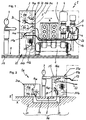
- FIG. 1 shown first embodiment of an inventive gas-insulated switchgear 1 with a in the horizontal direction (X) extending circuit breaker 2 and an end side arranged switching cabinet 3.
- the switchgear is arranged within a direction indicated by a dash-dotted line space and includes at least one gas-insulated switch 4 with at least one movable switching element 5.
- the movable switching element 5 interrupts or connects a first conductor section 6 with a second conductor section 7 of the switchgear 1.
- the conductor sections 6, 7 and the interior of the switch are shown only stylized.
- the switch 4 is a circuit breaker in this embodiment of the switchgear 1.
- an operating passage 8 extending in the Y-direction is arranged for an operator or technician 9.
- the operating gear 8 and the switchgear 1 itself are on a solid surface 17th
- the control cabinet 3 comprises a plurality of control units 10a, 10b, 10c for operating the switchgear 1, as well as a plurality Drive units 11a, 11b, 11c, 11d, 11e, the latter three only in conjunction with FIG. 3 are recognizable.
- the control and drive units are in FIG. 1 shown in phantom.
- the drive unit 11b is used to move at least one switching element of the circuit breaker 3.
- the drive unit 11b is clearly visible for better understanding of the reader through a partially broken cabinet wall of the drive cabinet 21.
- the drive unit 11a is used inter alia for transferring the at least one switching element 5 of the at least one switch 4 from a first position to a second position.
- the drive unit 11a has a switch drive 12 with an electric motor, which is arranged spatially away from the actual switch 4 close to the operation gear 8.
- the electric motor of the switch drive 12 acts here on a flexible mechanical shaft 13 on the movable switching element 5 a.
- the control units 10a, 10b, 10c are each electrically connected to a connection section 15 via first cables 14a, 14b, 14c.
- first cable subsumes both the singular number and the plural of an electrical or electronic connection line.
- control units 10a, 10b, 10c and the connection portion 15 are arranged in a control cabinet 20 and mechanically connected thereto. Electrically or electronically, the drive units 11a, 11b, 11c are connected to the connection section 15 via second cables 16a, 16b.
- the entirety of the first cables 14a, 14b, 14c and second cables 16a, 16b will also be referred to as electrical and / or electronic connections 27 in the following.
- control cabinet 20 and the drive cabinet 21 are mechanically designed as not or only partially independent modules, since they are in a higher-level mechanical structure of the cabinet 3 and its mechanical Frame are attached. However, the control units and the drive units are arranged according to their intended purpose in their own spatial areas of the cabinet 3, so that no interweaving of the electrical and / or electronic connections.
- the drive units 11a, 11b, 11c, 11d, 11e are arranged in a drive cabinet 21 and mechanically connected thereto.
- the drive cabinet 21 and the control cabinet 20 both have their own mechanical structure, which is at least partially integrated into the mechanical structure of the enclosing the control cabinet 3.
- embodiments of cabinets are possible in which the drive cabinet 21 and the control cabinet 20 both have their own mechanical structure, which can be joined together to form a one-piece cabinet block.
- connection section 15 is fastened to an inner side of a rear wall 22 of the control cabinet 20 facing the control panel.
- Another electrical and / or electronic connection in the form of a sensor line 23 (measuring line cable) is used to transmit electronic signals of a sensor attached to the switch 4 to the connection section 15 and from there for evaluation via a first cable 14a to an evaluation unit associated with the sensor in the Control unit 10a.
- FIG. 2 shown alternative second embodiment of the cabinet 3 is in the same representation as in FIG. 1 presented to illustrate the differences more clearly. Due to the similarity of the second embodiment of the cabinet 3 to in FIG. 1 shown first embodiment of the cabinet 3 will be discussed below only on the differences of the second embodiment with respect to the first embodiment. Accordingly, identical or identically acting parts are also provided with identical reference numerals or the like.
- control cabinet 3a has a respective control cabinet 20a and a drive cabinet 21a, both of which have their own mechanical structure and are therefore each mechanically independent modules.
- the drive cabinet 21a is arranged in this embodiment on a side opposite the control cabinet 20a side of the control gear 8. Below the operating passage 8 extends in the ground 17, a cable tray 24, in which the first cable 14 are guided by the control units 10 a, 10 b, 10 c to the connection portion 15 in the drive cabinet 15.
- the connection section 15 is arranged on an inner wall 25 of the drive cabinet 21a facing the access passage 8. Second cables 16a, 16b connect the drive units 11a, 11b electrically and / or electronically to the connection section 15.
- FIG. 3 A third embodiment of a control cabinet is described below with reference to FIG. 3 explained.
- This figure shows one of the drive cabinet 21b, which is raised only for illustrative purposes with respect to the control cabinet 20b.
- the control cabinet 20b is connected via fastening means 26 fixed to the drive cabinet 21b.
- at least one centering element for example a centering mandrel, can be provided.
- control cabinet 3b With reference to the third embodiment of the control cabinet 3b, reference will now be made in more detail to the design of the electrical and / or electronic connections 27 in the region of the connection section 15.
- control cabinet 20b is a tinny cube, which can be closed off in the X direction, that is to say in the direction of the operating passage, by means of a cover (not shown) or a cabinet door.
- the control cabinet 20b In the Z direction, the control cabinet 20b, with the exception of support zones 28a, 28b, is essentially open towards the drive cabinet 21b.
- This opening 29 in the control cabinet 20b dangle in the state shown by the control units 10a, 10b, 10c, 10d, 10e coming forth first cable 14a, 14b, 14c, 14d, 14e, which at their free ends depending on a plug 30a, 30b, 30c, 30d.
- These plugs 30a, 30b, 30c, 30d are suitable for corresponding sockets 34a, 34b, 34c, 34d (indicated by dash-dotted lines 27 marked with connections) of the drive cabinet 21b, which will be dealt with separately.
- the drive cabinet 21b is also a tinny cube which is open or closed in the Z direction as needed. In the direction of the control cabinet 20b, the drive cabinet 21b is closed by the connection section 15.
- the tinny connection section 15 forms a main body 33 which extends in a planar manner in a first plane 35 and a control cabinet interior 37 partially of a drive cabinet interior 38 separates.
- each is directly or indirectly connected to a second cable 16a, 16b, 16c, 16d via its associated sockets 34a, 34b, 34c, 34d.
- connection section 15 in addition to the sockets 34a, 34b, 34c, 34d fastened to it, also has recesses 36 which connect a control cabinet interior 37 with a drive cabinet interior 38 to a common temperature control of the cabinet interior 37, 38 with a cooling / heating unit, not shown to enable.
- control cabinet 20b and the drive cabinet 21b are designed mechanically as separate modules.
- the operator can conveniently connect the plugs 30a, 30b, 30c, 30d to the corresponding outlets 34a, 34b, 34c, 34d from the operating passage and thus quickly obtain a reliable electrical and / or electronic Effect a connection.
- the dashed lines shown first cable can alternatively be shown in a peripheral portion of the drive cabinet 21b by a seen in the Y direction laterally on the drive cabinet 21b leading cable duct 39, so that an interweaving of the first cable and the second cable in the drive cabinet interior 38 is elegantly avoidable.
- a cable duct attached to the wall section 40 can take over the task of the cable duct 39 if required.
Landscapes
- Engineering & Computer Science (AREA)
- Power Engineering (AREA)
- Patch Boards (AREA)
- Relay Circuits (AREA)
Applications Claiming Priority (1)
| Application Number | Priority Date | Filing Date | Title |
|---|---|---|---|
| DE102010063130A DE102010063130A1 (de) | 2010-12-15 | 2010-12-15 | Schaltschrank zum Betreiben einer Mittel- oder Hochspannungsschaltanlage |
Publications (2)
| Publication Number | Publication Date |
|---|---|
| EP2466706A2 true EP2466706A2 (fr) | 2012-06-20 |
| EP2466706A3 EP2466706A3 (fr) | 2014-06-18 |
Family
ID=45093542
Family Applications (1)
| Application Number | Title | Priority Date | Filing Date |
|---|---|---|---|
| EP11191864.5A Withdrawn EP2466706A3 (fr) | 2010-12-15 | 2011-12-05 | Armoire électrique pour le fonctionnement d'une installation de commutation à moyenne ou haute tension |
Country Status (4)
| Country | Link |
|---|---|
| EP (1) | EP2466706A3 (fr) |
| KR (1) | KR101290048B1 (fr) |
| CN (1) | CN102570337A (fr) |
| DE (1) | DE102010063130A1 (fr) |
Cited By (2)
| Publication number | Priority date | Publication date | Assignee | Title |
|---|---|---|---|---|
| CN103854914A (zh) * | 2012-11-29 | 2014-06-11 | 株式会社日立制作所 | 气体断路器 |
| EP3671992A1 (fr) * | 2018-12-19 | 2020-06-24 | ABB Schweiz AG | Appareillage de commutation ou de commande |
Families Citing this family (1)
| Publication number | Priority date | Publication date | Assignee | Title |
|---|---|---|---|---|
| DE102016202327A1 (de) * | 2016-02-16 | 2017-08-17 | Siemens Aktiengesellschaft | Antriebsanordnung zur Ausbildung einer Trennstrecke für einen Überspannungsableiter |
Citations (2)
| Publication number | Priority date | Publication date | Assignee | Title |
|---|---|---|---|---|
| EP1068624B1 (fr) | 1998-04-03 | 2002-01-02 | Siemens Aktiengesellschaft | Module d'encapsulage dote d'un commutateur a trois positions integre dans un circuit electrique et destine a un equipement electrique isole par un gaz |
| EP1569254A1 (fr) | 2004-02-27 | 2005-08-31 | ABB Technology AG | Interrupteur de mise à la terre et/ou sectionneur |
Family Cites Families (16)
| Publication number | Priority date | Publication date | Assignee | Title |
|---|---|---|---|---|
| DE2606369C2 (de) * | 1976-02-18 | 1982-09-09 | Licentia Patent-Verwaltungs-Gmbh, 6000 Frankfurt | Anordnung zur Steuerung von Schaltgeräten in Hochspannungs-Schaltanlagen |
| DE4210368A1 (de) * | 1992-03-30 | 1993-10-07 | Abb Patent Gmbh | Hochspannungsschaltfeld |
| DE4226472C5 (de) * | 1992-08-10 | 2005-07-21 | Alstom Sachsenwerk Gmbh | Schaltanlage |
| DE29620437U1 (de) * | 1996-11-13 | 1997-02-06 | Siemens AG, 80333 München | Kapselungsgehäuse für gasisolierte, metallgekapselte Schaltanlagen |
| DE19850430A1 (de) * | 1997-12-18 | 1999-07-08 | Siemens Ag | Gasisolierte Hochspannungsschaltanlage mit einer Trennschaltstrecke |
| DE19809839A1 (de) * | 1998-03-02 | 1999-09-09 | Siemens Ag | Metallgekapselte, gasisolierte Schaltanlage mit gasgefüllten Behältern |
| KR100356512B1 (ko) | 1999-05-20 | 2002-10-18 | 엘지산전 주식회사 | 가스 절연 배전반 |
| CN2402098Y (zh) * | 1999-09-09 | 2000-10-18 | 任国海 | 一种教学用实验台 |
| CN1217459C (zh) * | 1999-09-29 | 2005-08-31 | 株式会社日立制作所 | 气体绝缘开关装置 |
| DE10203035B4 (de) * | 2002-01-26 | 2010-04-15 | Abb Ag | Gasisolierte Hochspannungsschaltanlage |
| JP4829021B2 (ja) * | 2006-07-12 | 2011-11-30 | 株式会社東芝 | ガス絶縁開閉装置 |
| DE102006040035A1 (de) * | 2006-08-23 | 2008-02-28 | Siemens Ag | Anordnung mit einem Zubehörbehälter |
| JP4876008B2 (ja) * | 2007-03-27 | 2012-02-15 | 富士フイルム株式会社 | ポリエステル樹脂フィルムの製造方法 |
| DE102008017429A1 (de) * | 2007-04-05 | 2008-10-09 | Abb Technology Ag | Nieder-, Mittel- oder Hochspannungsschalt- oder -steuereinrichtung, insbesondere eine Schaltanlage |
| DE102007047200A1 (de) * | 2007-05-31 | 2008-12-04 | Abb Technology Ag | Hochspannungsschaltanlage |
| KR100905020B1 (ko) * | 2007-08-07 | 2009-06-30 | 엘에스산전 주식회사 | 스위치기어의 모선연결장치 및 그의 모선연결방법 |
-
2010
- 2010-12-15 DE DE102010063130A patent/DE102010063130A1/de not_active Withdrawn
-
2011
- 2011-12-05 EP EP11191864.5A patent/EP2466706A3/fr not_active Withdrawn
- 2011-12-15 KR KR1020110135440A patent/KR101290048B1/ko not_active Expired - Fee Related
- 2011-12-15 CN CN2011104368714A patent/CN102570337A/zh active Pending
Patent Citations (2)
| Publication number | Priority date | Publication date | Assignee | Title |
|---|---|---|---|---|
| EP1068624B1 (fr) | 1998-04-03 | 2002-01-02 | Siemens Aktiengesellschaft | Module d'encapsulage dote d'un commutateur a trois positions integre dans un circuit electrique et destine a un equipement electrique isole par un gaz |
| EP1569254A1 (fr) | 2004-02-27 | 2005-08-31 | ABB Technology AG | Interrupteur de mise à la terre et/ou sectionneur |
Cited By (5)
| Publication number | Priority date | Publication date | Assignee | Title |
|---|---|---|---|---|
| CN103854914A (zh) * | 2012-11-29 | 2014-06-11 | 株式会社日立制作所 | 气体断路器 |
| EP3671992A1 (fr) * | 2018-12-19 | 2020-06-24 | ABB Schweiz AG | Appareillage de commutation ou de commande |
| CN111342385A (zh) * | 2018-12-19 | 2020-06-26 | Abb瑞士股份有限公司 | 开关装置或控制装置 |
| US11139642B2 (en) | 2018-12-19 | 2021-10-05 | Abb Schweiz Ag | Switchgear or control gear |
| CN111342385B (zh) * | 2018-12-19 | 2022-03-04 | Abb瑞士股份有限公司 | 开关装置或控制装置 |
Also Published As
| Publication number | Publication date |
|---|---|
| CN102570337A (zh) | 2012-07-11 |
| KR20120067307A (ko) | 2012-06-25 |
| DE102010063130A1 (de) | 2012-06-21 |
| KR101290048B1 (ko) | 2013-07-30 |
| EP2466706A3 (fr) | 2014-06-18 |
Similar Documents
| Publication | Publication Date | Title |
|---|---|---|
| EP0709932B1 (fr) | Installation de réglage avec bus, par example pour l'automation d'édifice | |
| EP0491260B1 (fr) | Dispositif de câblage | |
| EP3631922B1 (fr) | Tableau de distribution | |
| EP2587513A1 (fr) | Commutateur d'installation doté d'une unité de capteur de courant | |
| DE102017107040A1 (de) | Installierbarer bausatz eines motorisierten sekundären verbinderfeldes eines unterbrechers | |
| EP2135337B1 (fr) | Dispositif de distribution ou de commande basse, moyenne ou haute tension, notamment installation de distribution | |
| DE69232354T2 (de) | Energieversorgungsaggregat für ein Stromverteilungssystem | |
| EP1867020B1 (fr) | Face arriere modulaire pour module d'installation de distribution, module d'installation de distribution et installation de distribution electrique | |
| EP2258153B1 (fr) | Système modulaire électrique comprenant un module de bus de terrain à utilisation variable | |
| EP3185365A1 (fr) | Rail d'alimentation | |
| EP2023364A1 (fr) | Commutateur électromagnétique doté de plusieurs zones dégradées les unes par rapport aux autres | |
| DE102010063130A1 (de) | Schaltschrank zum Betreiben einer Mittel- oder Hochspannungsschaltanlage | |
| EP2555003B1 (fr) | Transducteur de courant et sectionneur de charge étant équipé avec celui-ci | |
| DE102004036163B4 (de) | Steuereinrichtung für elektrohydraulische Ausbausteuerungen | |
| EP1218907B1 (fr) | Ensemble actionneur comprenant au moins deux actionneurs et une unite de commande sure | |
| EP3020975B1 (fr) | Appareil a vide | |
| EP2217811B1 (fr) | Systeme d'installation electrique de type modulaire | |
| DE10052846C2 (de) | Anordnung zur Verzweigung elektrischer Stromkreise im explosionsgefährdeten Bereich | |
| EP2466604B1 (fr) | Unité d'entraînement pour le fonctionnement d'un interrupteur d'une installation de commutation à moyenne ou haute tension | |
| DE19854584B4 (de) | Elektrische Installationsgeräte, insbesondere Schutzkontaktsteckdosenanordnungen | |
| EP0268305B1 (fr) | Dispositif pour la connexion antidéflagrante et protégée contre le grisou de moyens de fabrication à une ligne électrique | |
| DE102010021151B4 (de) | Steuergeräteanordnung an einer Halteschiene und elektrischer Schaltschrank mit einer solchen Steuergeräteanordnung | |
| EP3706248B1 (fr) | Boitier de distribution | |
| DE19742525C1 (de) | Schnittstelleneinrichtung | |
| DE102020212249A1 (de) | Kabelverlegekasten, elektrischer Schalter mit solch einem Kabelverlegekasten und Schaltschrank mit solch einem Kabelverlegekasten |
Legal Events
| Date | Code | Title | Description |
|---|---|---|---|
| PUAI | Public reference made under article 153(3) epc to a published international application that has entered the european phase |
Free format text: ORIGINAL CODE: 0009012 |
|
| AK | Designated contracting states |
Kind code of ref document: A2 Designated state(s): AL AT BE BG CH CY CZ DE DK EE ES FI FR GB GR HR HU IE IS IT LI LT LU LV MC MK MT NL NO PL PT RO RS SE SI SK SM TR |
|
| AX | Request for extension of the european patent |
Extension state: BA ME |
|
| PUAL | Search report despatched |
Free format text: ORIGINAL CODE: 0009013 |
|
| AK | Designated contracting states |
Kind code of ref document: A3 Designated state(s): AL AT BE BG CH CY CZ DE DK EE ES FI FR GB GR HR HU IE IS IT LI LT LU LV MC MK MT NL NO PL PT RO RS SE SI SK SM TR |
|
| AX | Request for extension of the european patent |
Extension state: BA ME |
|
| RIC1 | Information provided on ipc code assigned before grant |
Ipc: H02B 1/30 20060101ALI20140512BHEP Ipc: H02B 1/20 20060101AFI20140512BHEP Ipc: H02B 13/035 20060101ALI20140512BHEP |
|
| 17P | Request for examination filed |
Effective date: 20141219 |
|
| RBV | Designated contracting states (corrected) |
Designated state(s): AL AT BE BG CH CY CZ DE DK EE ES FI FR GB GR HR HU IE IS IT LI LT LU LV MC MK MT NL NO PL PT RO RS SE SI SK SM TR |
|
| 17Q | First examination report despatched |
Effective date: 20151117 |
|
| STAA | Information on the status of an ep patent application or granted ep patent |
Free format text: STATUS: THE APPLICATION IS DEEMED TO BE WITHDRAWN |
|
| 18D | Application deemed to be withdrawn |
Effective date: 20160330 |