EP2467275B1 - Kfz-fenster mit dichtung und zierleiste - Google Patents
Kfz-fenster mit dichtung und zierleiste Download PDFInfo
- Publication number
- EP2467275B1 EP2467275B1 EP10742539.9A EP10742539A EP2467275B1 EP 2467275 B1 EP2467275 B1 EP 2467275B1 EP 10742539 A EP10742539 A EP 10742539A EP 2467275 B1 EP2467275 B1 EP 2467275B1
- Authority
- EP
- European Patent Office
- Prior art keywords
- gasket
- vehicle glazing
- retaining clip
- retaining
- fit
- Prior art date
- Legal status (The legal status is an assumption and is not a legal conclusion. Google has not performed a legal analysis and makes no representation as to the accuracy of the status listed.)
- Active
Links
Images
Classifications
-
- B—PERFORMING OPERATIONS; TRANSPORTING
- B60—VEHICLES IN GENERAL
- B60J—WINDOWS, WINDSCREENS, NON-FIXED ROOFS, DOORS, OR SIMILAR DEVICES FOR VEHICLES; REMOVABLE EXTERNAL PROTECTIVE COVERINGS SPECIALLY ADAPTED FOR VEHICLES
- B60J10/00—Sealing arrangements
- B60J10/20—Sealing arrangements characterised by the shape
- B60J10/26—Sealing arrangements characterised by the shape characterised by the surface shape
- B60J10/265—Sealing arrangements characterised by the shape characterised by the surface shape the surface being primarily decorative
-
- B—PERFORMING OPERATIONS; TRANSPORTING
- B60—VEHICLES IN GENERAL
- B60J—WINDOWS, WINDSCREENS, NON-FIXED ROOFS, DOORS, OR SIMILAR DEVICES FOR VEHICLES; REMOVABLE EXTERNAL PROTECTIVE COVERINGS SPECIALLY ADAPTED FOR VEHICLES
- B60J10/00—Sealing arrangements
- B60J10/30—Sealing arrangements characterised by the fastening means
-
- B—PERFORMING OPERATIONS; TRANSPORTING
- B60—VEHICLES IN GENERAL
- B60J—WINDOWS, WINDSCREENS, NON-FIXED ROOFS, DOORS, OR SIMILAR DEVICES FOR VEHICLES; REMOVABLE EXTERNAL PROTECTIVE COVERINGS SPECIALLY ADAPTED FOR VEHICLES
- B60J10/00—Sealing arrangements
- B60J10/70—Sealing arrangements specially adapted for windows or windscreens
Definitions
- the present invention relates to vehicle glazings having a gasket provided on at least one surface. More particularly, the present invention relates to vehicle glazings provided with retaining clips for retaining vehicle glazing components, to retaining clips for use with such glazings and to trims adapted to fit such glazings.
- the appearance of an automotive vehicle is a key factor in successful sales.
- a number of features contribute to the overall appearance of a vehicle, one of which is the trim associated with the doors and windows. Finishers, such as chrome-finish (bright trim) or plastic strips, are often added to fixed windows by being mounted on the glazing itself, rather than on the body of the vehicle. Such bright finishers can be optional features on so-called “top of the range” models. Trims for openable glazings are often provided on the vehicle door or body.
- the trim may be included in the mould used for the encapsulation, and therefore bonded to the glazing by the polymer frame.
- the trim may be bonded to the glazing by a layer or multiple points of adhesive along its length.
- the trim may be clipped to the edge of the glazing, either directly, or via a holder that is bonded to the glazing.
- GB 2 010 380 A discloses a plastics trim clip for a channel-shaped trim strip.
- the clip comprises a base with an upstanding rib along one side, a slot running along the base at an angle inclined to the rib for mounting on a stud, resilient fingers projecting upwardly and outwardly, and a shoulder.
- the trim strip is retained by the fingers and shoulder.
- This clip is intended for mounting on a stud welded to a panel, and not for mounting on a gasket.
- FR 2 886 219 A1 discloses a device for attaching a profiled trim to a portion of a shaped bead mounted on a glazing, for example mounted on at least part of the periphery of a glazing.
- the device includes at least one rigid clip including at least an upstream interacting part configured to allow interaction with the shaped bead and a downstream interacting part configured to allow interaction with the profiled trim.
- US 3,968,613 discloses a fastener attaching a trim moulding to a resilient pad adjacent an automobile window, wherein the resilient pad is provided with a longitudinal slit, and the fastener has a tongue-like extension projecting into the slit and a body portion which engages the trim moulding.
- Another aspect of good design for bright trim clips is their ability to avoid unwanted vehicle noises, such as rattles and squeaks and the like.
- the present invention aims to address these problems.
- the present invention accordingly provides, in a first aspect (see independent claim 1), a vehicle glazing having a gasket provided on at least one surface, the gasket extending along at least a portion of one edge of the glazing, and provided with at least one resilient asymmetric metal retaining clip for retaining a vehicle glazing component, wherein the retaining clip comprises a first limb having means for engaging the gasket, and a second limb having means for retaining the vehicle glazing component.
- the asymmetric retaining clip enables the use of significantly lower clearance so that the trim can be closer to the glass surface. Furthermore, it is advantageous to attach the vehicle glazing component to the gasket, rather than to the vehicle bodywork, and the retaining clip of the invention makes this possible.
- a vehicle glazing component normally has at least two sides, and it is preferable to secure the vehicle glazing component on at least two sides.
- the retaining clip retains a first side of the vehicle glazing component
- the gasket comprises a retaining gasket portion for retaining a second side of the vehicle glazing component.
- the retaining gasket portion is a protuberance shaped to fit the second side of the vehicle glazing component.
- the protuberance may be elongate, e.g. in the form of a shoulder. Using the protuberance on one side and the clip on the other can aid robustness and anti-noise properties.
- the vehicle glazing component will be a glazing trim.
- the trim may be of various colours and materials.
- one of the more preferred trims is a bright trim of a metallic, preferably silver colour.
- the gasket will usually comprise a channel adapted to receive the first side of the vehicle glazing component when the retaining clip is in position, the channel will also enable the asymmetric retaining clip portion to retain the first side of the vehicle glazing component, the width of the channel preferably being suitable for the asymmetric clip retaining portion to co-operate in fitting the first side of the vehicle glazing component.
- the gasket will usually comprise a ridge, preferably a ridge recessed into the material of the gasket (i.e. closer to the glass surface, adapted to fit the retaining clip).
- the ridge will generally extend along the edge of the glass on which the gasket has been provided.
- the ridge will preferably have an undercut region adapted to fit part of the retaining clip. More preferably, the undercut region will be on generally the same side of the retaining clip/ridge as the asymmetric retaining clip portion for retaining the first side of the vehicle glazing component. This is advantageous because the undercut region adapted to fit a part (e.g. a curved lip) of the retaining clip improves the efficiency and security of the fitting of the vehicle glazing component in the system.
- the gasket also comprises a groove adapted to fit a part of the retaining clip.
- the groove is relatively narrow. More preferably, the groove is on the other side of the ridge from the undercut portion and is shaped to accommodate a barbed portion of the retaining clip.
- the retaining clip is formed such that it comprises a channel portion adapted to fit the ridge of the gasket.
- the channel portion may be relatively short or may be elongate (elongation, for example, being along the axis of the ridge).
- the channel portion will comprise a back and arms/sidewall depending from the back.
- the asymmetric retaining clip portion preferably comprises means for engaging the vehicle glazing component in the form of a flange or tab extending to one side of the clip suitable for fitting the first side of the vehicle glazing component.
- the channel portion of the retaining clip comprises means for engaging a gasket in the form of mutually diverging lugs or barbs, especially a first barb adapted to fit in the gasket groove, the first barb being directed partially towards the asymmetric clip portion.
- the channel portion also comprises a second barb adapted to fit the gasket groove, the second barb being directed partially away from the asymmetric retaining clip portion.
- the first and/or second barbs are advantageous because fitting as they do in the narrow groove, they will resist withdrawal of the retaining clip and also provide, in cooperation with the flange of the asymmetric retaining clip portion, for a firm fitting of the vehicle glazing component into the gasket.
- the retaining clip may have a U-shaped section.
- the retaining clip is elongate, especially elongate in a direction perpendicular to the plane of the "U" of the U-shaped section such that the clip is in the form of an elongate channel, having a U-shaped cross-section.
- the direction of elongation will generally be along the ridge.
- the retaining clip is preferably asymmetric with respect to a plane that bisects the U-shaped cross-section of the clip, and is perpendicular to the plane of the "U". In the case of an elongate clip, the plane of asymmetry will therefore also be parallel to the direction of elongation of the clip.
- the gasket may be formed in situ on the sheet of glazing material, e.g. by encapsulation (injection moulding) or by extrusion and is generally of a polymer or polymers already known for use in forming gaskets on a vehicle glazing.
- polymers include polyurethanes, PVC, TPE-V, TPO , EPDM or other such known glass encapsulation materials.
- the vehicle glazing of the present invention may further comprise a vehicle glazing component mounted on the retaining clip.
- the vehicle glazing component is preferably a glazing trim although other glazing components may be accommodated including waterproof cowlings and/or water trays along the bottom edge of a windscreen, applique panels, wire harness carriers, covers etc.
- the present invention provides a resilient asymmetric metal retaining clip for mounting on a gasket to retain a vehicle glazing component in the vicinity of the gasket, the retaining clip having a generally U-shaped section, the "U” comprising a base and two limbs, the first limb comprising means for engaging the gasket, and the second limb comprising means for engaging the vehicle glazing component, wherein the means for engaging the gasket comprises at least two lugs extending from the first limb in mutually diverging directions, and the second limb comprises a tab extending outwardly from the limb to engage the vehicle glazing component.
- the retaining clip may be generally as described above.
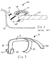
- Figure 1 illustrates a known vehicle glazing 102 comprising a sheet 104 of glazing material, e.g. glass, and a gasket 105.
- the glazing is mounted within an aperture in a vehicle body 108 by means of a bead of adhesive (not shown) in contact with the gasket 105 provided around at least a portion of the periphery of the vehicle glazing 102.
- the gasket 105 comprises a lip portion 106 that bears against the edge of the aperture in the vehicle body 108.
- the main body of the gasket 105 is formed on the surface of the vehicle glazing 102 that faces away from the vehicle body. This is the portion of the gasket 105 that serves to mount a trim 110 along an edge of the vehicle glazing 102.
- the position of the trim 110 is very close to the edge of the vehicle body, resulting in tight tolerances when fitting the trim 110 on a glazing production line.
- FIG. 1 the option of using a known type of retaining clip 119 is shown.
- the known retaining clip 119 is symmetrical and generally "C"-shaped in cross section and is sized to fit over a portion of the gasket 105. This clip can be used where space permits but works by clipping the trim on both sides/edges. Trim stability and strength depends largely on the clip alone, and the clip takes up additional space between the gasket and the vehicle body.
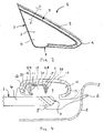
- FIG 2 shows a front quarter light vehicle glazing 2 of generally triangular shape installed in a car body (not shown).
- the vehicle glazing 2 comprises a sheet of glazing material in the form of a pane of glass 4 having a surface 3 and edges 7.
- the glazing further comprises a gasket 5 extending along the long edge of the glazing 2, around the corner 9, and onto a portion of one of the short edges.
- the gasket 2 is designed to fit and co-operate with a retaining clip according to the invention as illustrated in Figures 3 , 4 and 5 .
- the gasket is provided with a specially shaped ridge for this purpose, which is described more fully below.
- FIG. 3 illustrates one embodiment of a resilient asymmetric metal retaining clip 19 according to the invention.
- the retaining clip 19 has a generally U-shaped configuration in section, comprising a base portion 31 and two limbs in the form of depending arms 33, 35 which constitute the sides of the "U".
- the arms 33, 35 fit on either side of a ridge in the gasket.
- One arm 33 is provided with means for engaging a gasket in the form of lugs 39, 41.
- Arm 33 has two mutually diverging lugs 39, 41 which, when the retaining clip 19 is installed on a gasket, fit into a narrow groove between the ridge and the main body of the gasket and act as barbs to resist withdrawal of the clip 19 from the gasket.
- the lugs may have serrations, teeth, or other sharp, angular forms to improve their grip on the gasket.
- Curved arm 35 is shaped so as to fit an undercut portion of the ridge of the gasket.
- the flange or tab 37 extending from the base portion 31 is shaped to fit and retain one side of a trim to be fitted to the gasket.
- the overall shape of the clip is asymmetric about a plane which bisects the "U" and is perpendicular to the plane in which the "U" lies.
- FIG 4 shows a cross section through the glazing of Figure 2 on line A - A.
- the vehicle bodywork 8 and a vehicle glazing component in the form of a decorative trim strip 10 are also shown.
- the edge 7 of the glass 4 has an encapsulated gasket 5 with a lip 6 intended to form a seal against car body 8.
- the gasket 5 has a protuberance 14 and a shaped ridge 15 with a narrow groove 17 on one side nearer the protuberance 14 and a broader channel 21 on the other side, towards the centre of the glazing.
- a second embodiment of retaining clip 19 has a base 20 and first and second limbs in the form of depending arms 22 and 11 which are shaped to fit on the ridge 15.
- the first arm 22 of the retaining clip has a curved lip 24 to fit an undercut on the ridge 15.
- the second arm 11 has mutually diverging lugs 26 and 28, acting as barbs to resist withdrawal from the groove 17, and directed towards the protuberance 14 and away from the protuberance 14 respectively.
- a first barb is directed towards the other limb 22, and a second barb is directed away from it.
- a flange or tab 18 extends from the base 20 of the retaining clip and is shaped to retain the first side 16 of the trim 10
- the channel 21 is broad enough to allow space for the side 16 of the trim and tab 18 to cooperate.
- the protuberance 14 is shaped to fit and retain the second side 12 of trim 10.
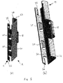
- FIGS 5(a) and 5(b) show perspective views of the second embodiment of retaining clip 19 as illustrated in use in Figure 4 .
- the retaining clip 19 is elongate with a base 20 from which depend arms 22 and 11 to form an elongate channel for fitting over the ridge 15 of the gasket 5.
- the clip has a longitudinal axis extending parallel to the direction of elongation of the channel.
- Arm 11 has mutually diverging lugs 28, 26 directed into and away from the elongate channel respectively.
- the lugs 26 are shown with an open edge, and the edge of the lugs may be serrated or otherwise provided with teeth to improve the grip of the lugs in the gasket. To strengthen these lugs 26 there may be material connecting the open edge to the base 20.
- the arm 22 has a curved lip 24 shaped to fit an undercut on the ridge 15.
- a flange or tab 18 extending from the base 20 and shaped to fit an edge of the trim, when the clip is position in the gasket.
- the clip is again generally U-shaped in cross-section, the overall shape of the clip is asymmetric about a plane bisecting its U-shaped cross-section. This plane is perpendicular to the elongate base 20 and also, when the clip is positioned in use, to the surface of the ridge 15; the plane is parallel to the arms, 22, 11 and the longitudinal axis of the clip.
- the retaining clip is preferably formed from spring steel, and may have a corrosion-resistant coating.
- the retaining clip may be pressed and bent into the shape of a channel, with lugs 26 and 28 being stamped out before or after shaping.
- the length of the base 20 and hence of the elongate retaining clip is in the range 10 to 80 mm, more preferably 20 to 60mm, with the height of the arms 11 and 22 being in the range of 1 to 5 mm, preferably 2.0 to 3.5mm.
- the base may be continuous, i.e. free from slots, perforations or other apertures.
- Several clips of either or each embodiment may be required to fit one trim 10 to an edge of a vehicle glazing.
- the gasket 5 may be formed from a polymer material, preferably a polymer material suitable for use with a rapid injection moulding process, as described in EP 0 792 209 B1 , or an extrusion process. It may be desirable to use an extrusion technology, again to extrude a polymer material, or a bonding technology, such as that known as bond-on-lace, in place of encapsulation, to form the gasket 5.
- the retaining clip of the present invention may be used to mount other vehicle glazing components.
- the retaining clip may be used to mount a waterproof cowling and/or water tray along the bottom edge of a windscreen.
- Suitable vehicle glazing components are those that require positioning along an edge of a vehicle glazing, making them ideal for use with a retaining clip in accordance with the present invention.
- the gasket into which the retaining clip is fitted has a lip portion only along a portion or its length, or is provided without a lip portion, depending on the position of the gasket on the vehicle glazing and the ultimate position of the vehicle glazing within a vehicle.
Landscapes
- Engineering & Computer Science (AREA)
- Mechanical Engineering (AREA)
- Connection Of Plates (AREA)
- Seal Device For Vehicle (AREA)
- Securing Of Glass Panes Or The Like (AREA)
Claims (15)
- Fahrzeugverglasung (2) mit einer Dichtung (5) auf zumindest einer Oberfläche (3), wobei der Dichtring (3) sich entlang zumindest eines Teils einer Kante (7) der Verglasung erstreckt, ausgestattet mit zumindest einem federnden asymmetrischen Metall-Befestigungsclip (19) zum Befestigen eines Fahrzeugverglasungsbauteils (10), wobei der Befestigungsclip erste und zweite Fortsätze (11, 33; 22, 35) umfasst, wobei der erste Fortsatz (11, 33) Mittel (26, 28; 39, 41) zum Greifen der Dichtung und der zweite Fortsatz (22, 35) Mittel (18, 37) zum Halten des Fahrzeugverglasungsbauteils (10) umfasst, dadurch gekennzeichnet, dass das Fahrzeugverglasungsbauteil zwei Seiten (16, 12) hat, wobei der Befestigungsclip (19) die erste Seite (16) des Fahrzeugverglasungsbauteils hält und die Dichtung (5) einen Halte-Dichtringbereich (14) zum Halten der zweiten Seite (12) des Fahrzeugverglasungsbauteils umfasst.
- Fahrzeugverglasung nach Anspruch 1, wobei das Fahrzeugverglasungsbauteil eine Fahrzeugverglasungszierleiste (10) ist.
- Fahrzeugverglasung nach Anspruch 1 oder 2, wobei die Dichtung (5) einen Kanal (21) umfasst, der dazu ausgelegt ist, die erste Seite (16) des Fahrzeugverglasungsbauteils (10) aufzunehmen.
- Fahrzeugverglasung nach einem der vorhergehenden Ansprüche, wobei die Dichtung (5) eine Rippe (15), vorzugsweise eine eingelassene Rippe, umfasst, die passend zum Befestigungsclip (19) ausgebildet ist.
- Fahrzeugverglasung nach Anspruch 4, wobei die Rippe (15) einen hinterschnittenen Bereich hat, der passend zu einem Teil (24) des Befestigungsclips (19) ausgebildet ist.
- Fahrzeugverglasung nach einem der vorhergehenden Ansprüche, wobei die Dichtung(5) eine Rille (17) umfasst, die so ausgelegt ist, dass ein Teil des Befestigungsclips (19) eingehängt werden kann.
- Fahrzeugverglasung nach einem der Ansprüche 4 bis 6, wobei der Befestigungsclip (19) so ausgebildet ist, dass er einen Kanalbereich umfasst, der so ausgelegt ist, dass er an die Rippe (15) der Dichtung (5) angepasst ist.
- Fahrzeugverglasung nach Anspruch 7, wobei der Kanalbereich eine gekrümmte Lippe (24) umfasst, die dazu ausgelegt ist, in den hinterschnittenen Bereich der Dichtungsrippe (15) eingehängt zu werden.
- Fahrzeugverglasung nach einem der vorhergehenden Ansprüche, dadurch gekennzeichnet, dass der asymmetrische Halteclipbereich einen Flansch oder einen Lappen (18) umfasst und sich nach einer Seite des Clips (19) erstreckt.
- Fahrzeugverglasung nach einem Ansprüche 7 bis 9, wobei der Kanalbereich einen ersten Widerhaken (28) umfasst, der dazu ausgelegt ist, in die Dichtungsrille (17) eingehängt zu werden, wobei der erste Widerhaken zu dem asymmetrischen Halteclipbereich hin ausgerichtet ist.
- Fahrzeugverglasung nach einem der Ansprüche 7 bis 10, wobei der Kanalbereich einen zweiten Widerhaken (26) umfasst, der dazu ausgelegt ist, in die Dichtungsrille (17) eingehängt zu sein, wobei der zweite Widerhaken von dem asymmetrischen Halteclipbereich fort ausgerichtet ist.
- Fahrzeugverglasung nach einem der vorhergehenden Ansprüche, wobei der Halteclip (19) die Form eines länglichen Kanals mit einem U-förmigen Querschnitt hat.
- Asymmetrischer Metallhalteclip (19) zum Befestigen eines Fahrzeugverglasungsbauteils (10), dadurch gekennzeichnet, dass der Halteclip die Form eines länglichen Kanals mit einem im Wesentlichen U-förmigen Querschnitt hat, wobei das "U" eine Basis (20, 31) und zwei Fortsätze umfasst, wobei der erste Fortsatz (11, 33) Mittel zum Greifen einer Dichtung (5) umfasst und der zweite Fortsatz (22, 25) Mittel zum Greifen eines Fahrzeugverglasungsbauteils (10) umfasst, wobei die Mittel zum Greifen einer Dichtung zumindest zwei Laschen (26, 28; 39, 41) umfassen, die sich von dem ersten Fortsatz aus in paarweise unterschiedliche Richtungen erstrecken, und die Mittel zum Greifen des Fahrzeugverglasungsbauteils des zweiten Fortsatzes eine Lasche (18, 37) umfassen, welche sich von dem Fortsatz aus nach außen erstreckt, wobei die Lasche so ausgebildet ist, dass sie eine Kante des Verglasungsbauteils greifen und halten kann wenn der Clip (19) auf der Dichtung (5) montiert ist.
- Halteclip nach Anspruch 13, wobei die Laschen (26, 28; 39, 41) mit Kerben, Zähnen oder anderen winkeligen Elementen ausgestattet sind, um den Dichtring (5) besser zu greifen.
- Halteclip nach Anspruch 13 oder Anspruch 14, wobei die beiden Fortsätze (11, 22; 33, 35) die Form von angeschlossenen Armen haben, welche die Seiten des "U" bilden und der den zweiten Fortsatz (22, 35) bildende Arm gekrümmt und so geformt ist, dass er auf einer Rippe (15) des Dichtrings (5) aufgesteckt werden kann.
Applications Claiming Priority (2)
| Application Number | Priority Date | Filing Date | Title |
|---|---|---|---|
| GBGB0914571.5A GB0914571D0 (en) | 2009-08-20 | 2009-08-20 | Vehicle glazing |
| PCT/GB2010/051288 WO2011021021A1 (en) | 2009-08-20 | 2010-08-04 | Vehicle glazing with seal and decoration strip |
Publications (2)
| Publication Number | Publication Date |
|---|---|
| EP2467275A1 EP2467275A1 (de) | 2012-06-27 |
| EP2467275B1 true EP2467275B1 (de) | 2014-01-22 |
Family
ID=41171671
Family Applications (1)
| Application Number | Title | Priority Date | Filing Date |
|---|---|---|---|
| EP10742539.9A Active EP2467275B1 (de) | 2009-08-20 | 2010-08-04 | Kfz-fenster mit dichtung und zierleiste |
Country Status (7)
| Country | Link |
|---|---|
| US (1) | US8925996B2 (de) |
| EP (1) | EP2467275B1 (de) |
| JP (1) | JP5571790B2 (de) |
| CN (1) | CN102470740B (de) |
| BR (1) | BR112012003437B1 (de) |
| GB (1) | GB0914571D0 (de) |
| WO (1) | WO2011021021A1 (de) |
Families Citing this family (18)
| Publication number | Priority date | Publication date | Assignee | Title |
|---|---|---|---|---|
| DE102008060448A1 (de) * | 2008-12-04 | 2010-06-17 | CADEA-Gesellschaft für Anwendung und Realisierung computerunterstützter Systeme mbH | Scheibeneinfassung |
| DE202010009720U1 (de) * | 2009-03-17 | 2011-02-10 | Pilkington Italia S.P.A. | Fahrzeugverkleidung mit einer daran montierten Zierleiste |
| JP5652007B2 (ja) * | 2010-06-07 | 2015-01-14 | 日産自動車株式会社 | 車両の窓部構造 |
| DE102011014540A1 (de) * | 2011-03-19 | 2012-09-20 | Audi Ag | Profildichtung mit Zierleiste für ein Fahrzeug |
| WO2014177329A1 (de) | 2013-04-30 | 2014-11-06 | Saint-Gobain Glass France | Abdichtungsanordnung für eine feste fahrzeugscheibe |
| MX367182B (es) * | 2013-06-26 | 2019-08-08 | Saint Gobain | Disposicion de sellado para una ventana de vehiculo. |
| CN103754170B (zh) * | 2014-01-07 | 2016-05-18 | 福耀玻璃工业集团股份有限公司 | 一种中间嵌件和玻璃窗 |
| CN104943517B (zh) * | 2014-03-31 | 2019-12-17 | 法国圣戈班玻璃公司 | 包边结构及其形成方法、车窗 |
| DE102015013974A1 (de) * | 2015-10-29 | 2017-05-04 | Henniges Automotive Gmbh & Co. Kg | Scheibenanordnung, insbesondere Karosserie-Scheibenanordnung |
| FR3051730B1 (fr) * | 2016-05-30 | 2018-06-29 | Saint-Gobain Glass France | Vitrage a joint profile et enjoliveur et procede de fabrication du vitrage. |
| FR3064545B1 (fr) * | 2017-03-30 | 2019-04-05 | Saint-Gobain Glass France | Vitrage comprenant au moins un cordon profile pour la liaison entre deux vitres. |
| FR3064546B1 (fr) * | 2017-03-30 | 2019-04-05 | Saint-Gobain Glass France | Vitrage comprenant un seul cordon profile pour la liaison entre deux vitres. |
| FR3085915B1 (fr) * | 2018-09-13 | 2020-08-07 | Renault Sas | Dispositif de fixation d'une garniture sur une structure de caisse d'un vehicule automobile tel qu'un montant de baie |
| FR3089459B1 (fr) * | 2018-12-10 | 2020-11-13 | Hutchinson | Kit et procédé d’habillage d’un rail de porte d’un véhicule |
| US11338659B2 (en) | 2019-04-04 | 2022-05-24 | Hutchinson Sealing Systems | Method of making a weather strip and bright strip assembly for a vehicle door |
| CN111231855A (zh) * | 2020-01-16 | 2020-06-05 | 桂林皮尔金顿安全玻璃有限公司 | 车辆后三角窗亮条安装结构 |
| CN111319433B (zh) * | 2020-03-19 | 2021-10-22 | 北京汽车股份有限公司 | 玻璃导轨和车门 |
| CN115091930A (zh) * | 2022-06-24 | 2022-09-23 | 福耀玻璃工业集团股份有限公司 | 窗玻璃结构、窗玻璃总成及汽车 |
Family Cites Families (50)
| Publication number | Priority date | Publication date | Assignee | Title |
|---|---|---|---|---|
| US2606635A (en) * | 1950-07-28 | 1952-08-12 | Gen Motors Corp | Sealing strip |
| US2647289A (en) * | 1950-08-24 | 1953-08-04 | Kaiser Frazer Corp | Window weatherstripping |
| US2814525A (en) * | 1953-07-31 | 1957-11-26 | Chrysler Corp | Flexible sealing strip for windows |
| US3968613A (en) * | 1974-06-03 | 1976-07-13 | Usm Corporation | Trim molding assembly |
| GB1514017A (en) * | 1975-03-10 | 1978-06-14 | Shiroki Corp | Device for mounting a windshield surround |
| US4011635A (en) | 1975-11-26 | 1977-03-15 | Usm Corporation | Retainer clip |
| FR2340217A1 (fr) * | 1976-02-03 | 1977-09-02 | Renault | Montage d'enjoliveurs sur pare-brise colles |
| US4147005A (en) | 1976-11-09 | 1979-04-03 | Usm Corporation | Molding clip and method of assembly |
| SE7812858L (sv) | 1977-12-16 | 1979-06-17 | Usm Corp | Kantklammer |
| DE2756248A1 (de) | 1977-12-16 | 1979-06-21 | Tucker Metallwaren Gmbh | Klammer zur halterung von leisten, insbesondere zierleisten |
| DE2756207A1 (de) | 1977-12-16 | 1979-06-21 | Tucker Metallwaren Gmbh | Vorrichtung zur befestigung von fensterscheiben, insbesondere fahrzeugscheiben |
| JPS6023207Y2 (ja) * | 1978-07-31 | 1985-07-10 | マツダ株式会社 | 接着ウインドのモ−ルディングクリップ |
| GB2049010A (en) | 1979-02-21 | 1980-12-17 | British Leyland Cars Ltd | Improvements relating to vehicle windows |
| FR2450371A1 (fr) | 1979-02-28 | 1980-09-26 | Nifco Inc | Assemblage a agrafes et baguette decorative |
| US4401340A (en) * | 1981-12-03 | 1983-08-30 | General Motors Corporation | Window reveal molding |
| JPS60166514A (ja) * | 1984-02-08 | 1985-08-29 | Kinugawa Rubber Ind Co Ltd | ウインドパネル固定用コ−ナ−ジヨイントの取付構造 |
| DE3432592C2 (de) * | 1984-09-05 | 1986-09-04 | Daimler-Benz Ag, 7000 Stuttgart | Einglasungsprofil für Scheiben von Fahrzeugen, insbesondere von Kraftwagen |
| GB2168741B (en) | 1984-12-22 | 1988-01-13 | Austin Rover Group | Window trim |
| JPS61169716U (de) * | 1985-04-10 | 1986-10-21 | ||
| JPH0636977Y2 (ja) * | 1988-01-30 | 1994-09-28 | 株式会社ニフコ | 接着式ウインドのモール装着装置 |
| US4904014A (en) | 1988-08-26 | 1990-02-27 | General Motors Corporation | Decorative trim molding assembly |
| JP2522637Y2 (ja) * | 1988-10-31 | 1997-01-16 | 橋本フォーミング工業株式会社 | ウインドウモールディング |
| AU640718B2 (en) * | 1989-12-07 | 1993-09-02 | Hashimoto Forming Industry Co. Limited | Automobile window molding assembly |
| JPH06166514A (ja) * | 1992-03-06 | 1994-06-14 | Rengo Co Ltd | 銀含有トバモライト |
| US5396746A (en) * | 1994-01-07 | 1995-03-14 | Whitmer; Bruce F. | Molding construction |
| DE4428142A1 (de) | 1994-08-09 | 1996-02-22 | Pauli & Sohn Gmbh | Klemmhalter |
| IT1275082B (it) | 1994-11-16 | 1997-07-30 | Siv Soc Italiana Vetro | Procedimento e dispositivo per la fabbricazione di un complesso formato da un vetro di sicurezza dotato di una guarnizione poliuretanica |
| US5561003A (en) | 1994-11-30 | 1996-10-01 | Nicholas Plastics, Inc. | Molding |
| GB2313397B (en) | 1996-05-22 | 2000-08-23 | Emhart Inc | Resilient clip |
| FR2769886B1 (fr) | 1997-10-17 | 2000-03-10 | Magneti Marelli France | Dispositif de fermeture perfectionne pour tableau de bord de vehicule automobile |
| DE19818153B4 (de) * | 1998-04-23 | 2006-08-10 | Richard Fritz Gmbh + Co. Kg | Scheibeneinheit zum Einbauen in eine vorgegebene Öffnung von Kraftfahrzeugen und dergleichen |
| US8205389B1 (en) | 1999-11-12 | 2012-06-26 | Henniges Automotive Sealing Systems North America, Inc. | Window seal assembly having a T-shaped trim member |
| DE10247015B4 (de) | 2002-10-09 | 2005-02-03 | Metzeler Automotive Profile Systems Gmbh | Dichtungsprofil mit Zierleiste |
| US7140079B2 (en) | 2002-10-18 | 2006-11-28 | Honda Motor Co., Ltd. | Clip for coupling windshield trim to a vehicle |
| DE10255151A1 (de) | 2002-11-26 | 2004-06-09 | Dura Automotive Plettenberg Entwicklungs- Und Vertriebs Gmbh | Seitenscheibe für ein Fahrzeug, insbesondere einen Personenkraftwagen |
| DE10255669B3 (de) | 2002-11-28 | 2004-06-03 | Dura Automotive Plettenberg Entwicklungs- Und Vertriebs Gmbh | Seitenscheibe für ein Fahrzeug, insbesondere einen Personenkraftwagen |
| DE10259843B3 (de) | 2002-12-19 | 2004-08-26 | Metzeler Automotive Profile Systems Gmbh | Dichtungsanordnung, insbesondere zum Abdichten von Fensterscheiben eines Kraftfahrzeuges |
| GB2406352A (en) | 2003-07-31 | 2005-03-30 | Gencorp Property Inc | Releasable sealing, trimming or finishing strip |
| DE102004035680B4 (de) * | 2004-07-22 | 2015-12-31 | Henniges Automotive Gmbh & Co. Kg | Plattenförmiges Element mit an einem Elementrand angeordneten Profilteil |
| FR2886219B1 (fr) | 2005-05-26 | 2007-07-06 | Saint Gobain | Dispositif de fixation d'un profile enjoliveur sur un cordon profile |
| DE102005054721A1 (de) | 2005-11-17 | 2007-05-24 | Richard Fritz Gmbh + Co. Kg | Scheibeneinheit |
| FR2905430B1 (fr) | 2006-09-04 | 2008-10-24 | Renault Sas | Agrafe pour fixation de bandeau de portiere de vehicule automobile |
| JP4176795B2 (ja) | 2006-09-27 | 2008-11-05 | 本田技研工業株式会社 | 窓ガラスとガラスモールの取付構造 |
| WO2010025189A1 (en) | 2008-08-26 | 2010-03-04 | Cooper-Standard Automotive Inc. | Trim attachment method and associated product |
| FR2938026B1 (fr) * | 2008-11-05 | 2013-01-18 | Saint Gobain | Procede de montage d'une piece sur un cordon profile, dispositif de fixation intermediaire pour la fixation d'une piece sur un cordon profile et utilisation dudit dispositif. |
| DE202010009720U1 (de) * | 2009-03-17 | 2011-02-10 | Pilkington Italia S.P.A. | Fahrzeugverkleidung mit einer daran montierten Zierleiste |
| DE102009031006A1 (de) | 2009-06-29 | 2010-12-30 | Dura Automotive Body & Glass Systems Gmbh | Seitenscheibe für ein Kraftfahrzeug |
| US20110042848A1 (en) | 2009-08-24 | 2011-02-24 | Ash Charles E | Method of making a molded trim assembly |
| DE102010011321B4 (de) | 2010-03-13 | 2019-01-03 | Volkswagen Ag | Anordnung zur Befestigung einer Zierleiste an einer Fahrzeugscheibe |
| FR2965229B1 (fr) | 2010-09-28 | 2015-02-27 | Saint Gobain | Vitrage a joint profile encapsule et piece rapportee fixee au joint, element de fixation de la piece rapportee pour le vitrage et procede de fabrication du vitrage. |
-
2009
- 2009-08-20 GB GBGB0914571.5A patent/GB0914571D0/en not_active Ceased
-
2010
- 2010-08-04 BR BR112012003437-5A patent/BR112012003437B1/pt active IP Right Grant
- 2010-08-04 CN CN201080036705.9A patent/CN102470740B/zh active Active
- 2010-08-04 JP JP2012525206A patent/JP5571790B2/ja active Active
- 2010-08-04 EP EP10742539.9A patent/EP2467275B1/de active Active
- 2010-08-04 WO PCT/GB2010/051288 patent/WO2011021021A1/en not_active Ceased
- 2010-08-04 US US13/391,338 patent/US8925996B2/en active Active
Also Published As
| Publication number | Publication date |
|---|---|
| BR112012003437A2 (pt) | 2016-02-23 |
| US8925996B2 (en) | 2015-01-06 |
| JP5571790B2 (ja) | 2014-08-13 |
| EP2467275A1 (de) | 2012-06-27 |
| GB0914571D0 (en) | 2009-09-30 |
| JP2013502343A (ja) | 2013-01-24 |
| CN102470740A (zh) | 2012-05-23 |
| WO2011021021A1 (en) | 2011-02-24 |
| BR112012003437B1 (pt) | 2020-10-20 |
| US20120153659A1 (en) | 2012-06-21 |
| CN102470740B (zh) | 2015-03-25 |
Similar Documents
| Publication | Publication Date | Title |
|---|---|---|
| US8925996B2 (en) | Vehicle glazing | |
| US5561003A (en) | Molding | |
| US5702148A (en) | Exterior decorative surround molding module | |
| JP4522028B2 (ja) | 自動車のウェザーストリップ | |
| US8549790B2 (en) | Weatherstrip assembly | |
| EP1232887B1 (de) | Türzarge für Kraftfahrzeuge | |
| US9114693B2 (en) | Daylight opening system | |
| CN100471710C (zh) | 汽车遮阳顶棚系统的玻璃板结构 | |
| EP0678412B1 (de) | Dichtungsleisteanordnung | |
| CA2295073C (en) | Integrally formed b-pillar and belt-line window molding | |
| US20020062596A1 (en) | Sealing profile | |
| KR20120048635A (ko) | 통합 글래스런을 구비한 공압출 u자형 채널 | |
| KR20110083643A (ko) | 프로파일된 비드 상에 부분을 장착하는 방법, 프로파일된 비드 상에 부분을 부착시키기 위한 중간물 부착 디바이스, 유리 시트 및 상기 디바이스의 사용 | |
| KR101084563B1 (ko) | 자동차용 바이저 | |
| JP2000503931A (ja) | 型成形された硬質支持部材を有するフレキシブルグラスラン | |
| KR20080013923A (ko) | 장식 프로파일된 섹션을 성형된 밴드에 고정시키기 위한장치 | |
| EP4230452B1 (de) | Seitenverkleidungsanordnung und fahrzeug | |
| EP3047992A1 (de) | Fahrzeugverglasung | |
| EP0378419B1 (de) | Frontal einsetzbare bündige Scheibenführung | |
| CN111016815B (zh) | 一种车门c柱分缝密封条结构 | |
| GB2421268A (en) | Sealing, trimming and finishing strips and vehicle doors incorporating such strips | |
| WO2007020525A1 (en) | Window sealing and guiding arrangements for vehicle doors and windows | |
| JP3013979U (ja) | 自動車用バイザ | |
| JPH0211233Y2 (de) | ||
| JPH0222349Y2 (de) |
Legal Events
| Date | Code | Title | Description |
|---|---|---|---|
| PUAI | Public reference made under article 153(3) epc to a published international application that has entered the european phase |
Free format text: ORIGINAL CODE: 0009012 |
|
| 17P | Request for examination filed |
Effective date: 20120320 |
|
| AK | Designated contracting states |
Kind code of ref document: A1 Designated state(s): AL AT BE BG CH CY CZ DE DK EE ES FI FR GB GR HR HU IE IS IT LI LT LU LV MC MK MT NL NO PL PT RO SE SI SK SM TR |
|
| DAX | Request for extension of the european patent (deleted) | ||
| GRAP | Despatch of communication of intention to grant a patent |
Free format text: ORIGINAL CODE: EPIDOSNIGR1 |
|
| INTG | Intention to grant announced |
Effective date: 20130702 |
|
| GRAP | Despatch of communication of intention to grant a patent |
Free format text: ORIGINAL CODE: EPIDOSNIGR1 |
|
| INTG | Intention to grant announced |
Effective date: 20130913 |
|
| GRAS | Grant fee paid |
Free format text: ORIGINAL CODE: EPIDOSNIGR3 |
|
| GRAA | (expected) grant |
Free format text: ORIGINAL CODE: 0009210 |
|
| AK | Designated contracting states |
Kind code of ref document: B1 Designated state(s): AL AT BE BG CH CY CZ DE DK EE ES FI FR GB GR HR HU IE IS IT LI LT LU LV MC MK MT NL NO PL PT RO SE SI SK SM TR |
|
| REG | Reference to a national code |
Ref country code: GB Ref legal event code: FG4D |
|
| REG | Reference to a national code |
Ref country code: CH Ref legal event code: EP |
|
| REG | Reference to a national code |
Ref country code: AT Ref legal event code: REF Ref document number: 650612 Country of ref document: AT Kind code of ref document: T Effective date: 20140215 |
|
| REG | Reference to a national code |
Ref country code: IE Ref legal event code: FG4D |
|
| REG | Reference to a national code |
Ref country code: DE Ref legal event code: R096 Ref document number: 602010013309 Country of ref document: DE Effective date: 20140306 |
|
| REG | Reference to a national code |
Ref country code: NL Ref legal event code: VDEP Effective date: 20140122 |
|
| REG | Reference to a national code |
Ref country code: AT Ref legal event code: MK05 Ref document number: 650612 Country of ref document: AT Kind code of ref document: T Effective date: 20140122 |
|
| REG | Reference to a national code |
Ref country code: LT Ref legal event code: MG4D |
|
| PG25 | Lapsed in a contracting state [announced via postgrant information from national office to epo] |
Ref country code: LT Free format text: LAPSE BECAUSE OF FAILURE TO SUBMIT A TRANSLATION OF THE DESCRIPTION OR TO PAY THE FEE WITHIN THE PRESCRIBED TIME-LIMIT Effective date: 20140122 Ref country code: IS Free format text: LAPSE BECAUSE OF FAILURE TO SUBMIT A TRANSLATION OF THE DESCRIPTION OR TO PAY THE FEE WITHIN THE PRESCRIBED TIME-LIMIT Effective date: 20140522 Ref country code: NO Free format text: LAPSE BECAUSE OF FAILURE TO SUBMIT A TRANSLATION OF THE DESCRIPTION OR TO PAY THE FEE WITHIN THE PRESCRIBED TIME-LIMIT Effective date: 20140422 |
|
| PG25 | Lapsed in a contracting state [announced via postgrant information from national office to epo] |
Ref country code: FI Free format text: LAPSE BECAUSE OF FAILURE TO SUBMIT A TRANSLATION OF THE DESCRIPTION OR TO PAY THE FEE WITHIN THE PRESCRIBED TIME-LIMIT Effective date: 20140122 Ref country code: ES Free format text: LAPSE BECAUSE OF FAILURE TO SUBMIT A TRANSLATION OF THE DESCRIPTION OR TO PAY THE FEE WITHIN THE PRESCRIBED TIME-LIMIT Effective date: 20140122 Ref country code: CY Free format text: LAPSE BECAUSE OF FAILURE TO SUBMIT A TRANSLATION OF THE DESCRIPTION OR TO PAY THE FEE WITHIN THE PRESCRIBED TIME-LIMIT Effective date: 20140122 Ref country code: NL Free format text: LAPSE BECAUSE OF FAILURE TO SUBMIT A TRANSLATION OF THE DESCRIPTION OR TO PAY THE FEE WITHIN THE PRESCRIBED TIME-LIMIT Effective date: 20140122 Ref country code: PT Free format text: LAPSE BECAUSE OF FAILURE TO SUBMIT A TRANSLATION OF THE DESCRIPTION OR TO PAY THE FEE WITHIN THE PRESCRIBED TIME-LIMIT Effective date: 20140522 Ref country code: AT Free format text: LAPSE BECAUSE OF FAILURE TO SUBMIT A TRANSLATION OF THE DESCRIPTION OR TO PAY THE FEE WITHIN THE PRESCRIBED TIME-LIMIT Effective date: 20140122 Ref country code: SE Free format text: LAPSE BECAUSE OF FAILURE TO SUBMIT A TRANSLATION OF THE DESCRIPTION OR TO PAY THE FEE WITHIN THE PRESCRIBED TIME-LIMIT Effective date: 20140122 |
|
| PG25 | Lapsed in a contracting state [announced via postgrant information from national office to epo] |
Ref country code: BE Free format text: LAPSE BECAUSE OF FAILURE TO SUBMIT A TRANSLATION OF THE DESCRIPTION OR TO PAY THE FEE WITHIN THE PRESCRIBED TIME-LIMIT Effective date: 20140122 Ref country code: LV Free format text: LAPSE BECAUSE OF FAILURE TO SUBMIT A TRANSLATION OF THE DESCRIPTION OR TO PAY THE FEE WITHIN THE PRESCRIBED TIME-LIMIT Effective date: 20140122 Ref country code: HR Free format text: LAPSE BECAUSE OF FAILURE TO SUBMIT A TRANSLATION OF THE DESCRIPTION OR TO PAY THE FEE WITHIN THE PRESCRIBED TIME-LIMIT Effective date: 20140122 |
|
| REG | Reference to a national code |
Ref country code: DE Ref legal event code: R097 Ref document number: 602010013309 Country of ref document: DE |
|
| PG25 | Lapsed in a contracting state [announced via postgrant information from national office to epo] |
Ref country code: EE Free format text: LAPSE BECAUSE OF FAILURE TO SUBMIT A TRANSLATION OF THE DESCRIPTION OR TO PAY THE FEE WITHIN THE PRESCRIBED TIME-LIMIT Effective date: 20140122 Ref country code: DK Free format text: LAPSE BECAUSE OF FAILURE TO SUBMIT A TRANSLATION OF THE DESCRIPTION OR TO PAY THE FEE WITHIN THE PRESCRIBED TIME-LIMIT Effective date: 20140122 Ref country code: CZ Free format text: LAPSE BECAUSE OF FAILURE TO SUBMIT A TRANSLATION OF THE DESCRIPTION OR TO PAY THE FEE WITHIN THE PRESCRIBED TIME-LIMIT Effective date: 20140122 Ref country code: RO Free format text: LAPSE BECAUSE OF FAILURE TO SUBMIT A TRANSLATION OF THE DESCRIPTION OR TO PAY THE FEE WITHIN THE PRESCRIBED TIME-LIMIT Effective date: 20140122 |
|
| PG25 | Lapsed in a contracting state [announced via postgrant information from national office to epo] |
Ref country code: PL Free format text: LAPSE BECAUSE OF FAILURE TO SUBMIT A TRANSLATION OF THE DESCRIPTION OR TO PAY THE FEE WITHIN THE PRESCRIBED TIME-LIMIT Effective date: 20140122 Ref country code: SK Free format text: LAPSE BECAUSE OF FAILURE TO SUBMIT A TRANSLATION OF THE DESCRIPTION OR TO PAY THE FEE WITHIN THE PRESCRIBED TIME-LIMIT Effective date: 20140122 |
|
| PLBE | No opposition filed within time limit |
Free format text: ORIGINAL CODE: 0009261 |
|
| STAA | Information on the status of an ep patent application or granted ep patent |
Free format text: STATUS: NO OPPOSITION FILED WITHIN TIME LIMIT |
|
| 26N | No opposition filed |
Effective date: 20141023 |
|
| REG | Reference to a national code |
Ref country code: DE Ref legal event code: R097 Ref document number: 602010013309 Country of ref document: DE Effective date: 20141023 |
|
| PG25 | Lapsed in a contracting state [announced via postgrant information from national office to epo] |
Ref country code: MC Free format text: LAPSE BECAUSE OF FAILURE TO SUBMIT A TRANSLATION OF THE DESCRIPTION OR TO PAY THE FEE WITHIN THE PRESCRIBED TIME-LIMIT Effective date: 20140122 Ref country code: LU Free format text: LAPSE BECAUSE OF FAILURE TO SUBMIT A TRANSLATION OF THE DESCRIPTION OR TO PAY THE FEE WITHIN THE PRESCRIBED TIME-LIMIT Effective date: 20140804 |
|
| REG | Reference to a national code |
Ref country code: CH Ref legal event code: PL |
|
| GBPC | Gb: european patent ceased through non-payment of renewal fee |
Effective date: 20140804 |
|
| PG25 | Lapsed in a contracting state [announced via postgrant information from national office to epo] |
Ref country code: LI Free format text: LAPSE BECAUSE OF NON-PAYMENT OF DUE FEES Effective date: 20140831 Ref country code: CH Free format text: LAPSE BECAUSE OF NON-PAYMENT OF DUE FEES Effective date: 20140831 |
|
| REG | Reference to a national code |
Ref country code: IE Ref legal event code: MM4A |
|
| PG25 | Lapsed in a contracting state [announced via postgrant information from national office to epo] |
Ref country code: SI Free format text: LAPSE BECAUSE OF FAILURE TO SUBMIT A TRANSLATION OF THE DESCRIPTION OR TO PAY THE FEE WITHIN THE PRESCRIBED TIME-LIMIT Effective date: 20140122 |
|
| PG25 | Lapsed in a contracting state [announced via postgrant information from national office to epo] |
Ref country code: GB Free format text: LAPSE BECAUSE OF NON-PAYMENT OF DUE FEES Effective date: 20140804 |
|
| PG25 | Lapsed in a contracting state [announced via postgrant information from national office to epo] |
Ref country code: IE Free format text: LAPSE BECAUSE OF NON-PAYMENT OF DUE FEES Effective date: 20140804 |
|
| PG25 | Lapsed in a contracting state [announced via postgrant information from national office to epo] |
Ref country code: SM Free format text: LAPSE BECAUSE OF FAILURE TO SUBMIT A TRANSLATION OF THE DESCRIPTION OR TO PAY THE FEE WITHIN THE PRESCRIBED TIME-LIMIT Effective date: 20140122 |
|
| PG25 | Lapsed in a contracting state [announced via postgrant information from national office to epo] |
Ref country code: IT Free format text: LAPSE BECAUSE OF FAILURE TO SUBMIT A TRANSLATION OF THE DESCRIPTION OR TO PAY THE FEE WITHIN THE PRESCRIBED TIME-LIMIT Effective date: 20140122 Ref country code: MT Free format text: LAPSE BECAUSE OF FAILURE TO SUBMIT A TRANSLATION OF THE DESCRIPTION OR TO PAY THE FEE WITHIN THE PRESCRIBED TIME-LIMIT Effective date: 20140122 Ref country code: BG Free format text: LAPSE BECAUSE OF FAILURE TO SUBMIT A TRANSLATION OF THE DESCRIPTION OR TO PAY THE FEE WITHIN THE PRESCRIBED TIME-LIMIT Effective date: 20140122 Ref country code: GR Free format text: LAPSE BECAUSE OF FAILURE TO SUBMIT A TRANSLATION OF THE DESCRIPTION OR TO PAY THE FEE WITHIN THE PRESCRIBED TIME-LIMIT Effective date: 20140423 |
|
| PG25 | Lapsed in a contracting state [announced via postgrant information from national office to epo] |
Ref country code: HU Free format text: LAPSE BECAUSE OF FAILURE TO SUBMIT A TRANSLATION OF THE DESCRIPTION OR TO PAY THE FEE WITHIN THE PRESCRIBED TIME-LIMIT; INVALID AB INITIO Effective date: 20100804 Ref country code: TR Free format text: LAPSE BECAUSE OF FAILURE TO SUBMIT A TRANSLATION OF THE DESCRIPTION OR TO PAY THE FEE WITHIN THE PRESCRIBED TIME-LIMIT Effective date: 20140122 |
|
| REG | Reference to a national code |
Ref country code: FR Ref legal event code: PLFP Year of fee payment: 7 |
|
| REG | Reference to a national code |
Ref country code: FR Ref legal event code: PLFP Year of fee payment: 8 |
|
| PG25 | Lapsed in a contracting state [announced via postgrant information from national office to epo] |
Ref country code: MK Free format text: LAPSE BECAUSE OF FAILURE TO SUBMIT A TRANSLATION OF THE DESCRIPTION OR TO PAY THE FEE WITHIN THE PRESCRIBED TIME-LIMIT Effective date: 20140122 |
|
| REG | Reference to a national code |
Ref country code: FR Ref legal event code: PLFP Year of fee payment: 9 |
|
| PG25 | Lapsed in a contracting state [announced via postgrant information from national office to epo] |
Ref country code: AL Free format text: LAPSE BECAUSE OF FAILURE TO SUBMIT A TRANSLATION OF THE DESCRIPTION OR TO PAY THE FEE WITHIN THE PRESCRIBED TIME-LIMIT Effective date: 20140122 |
|
| P01 | Opt-out of the competence of the unified patent court (upc) registered |
Effective date: 20230512 |
|
| PGFP | Annual fee paid to national office [announced via postgrant information from national office to epo] |
Ref country code: DE Payment date: 20250819 Year of fee payment: 16 |
|
| PGFP | Annual fee paid to national office [announced via postgrant information from national office to epo] |
Ref country code: FR Payment date: 20250821 Year of fee payment: 16 |