EP2467324B1 - Procédé et dispositif pour déposer une bande de matière souple - Google Patents
Procédé et dispositif pour déposer une bande de matière souple Download PDFInfo
- Publication number
- EP2467324B1 EP2467324B1 EP10740642.3A EP10740642A EP2467324B1 EP 2467324 B1 EP2467324 B1 EP 2467324B1 EP 10740642 A EP10740642 A EP 10740642A EP 2467324 B1 EP2467324 B1 EP 2467324B1
- Authority
- EP
- European Patent Office
- Prior art keywords
- laying
- air nozzles
- material web
- air
- station
- Prior art date
- Legal status (The legal status is an assumption and is not a legal conclusion. Google has not performed a legal analysis and makes no representation as to the accuracy of the status listed.)
- Not-in-force
Links
- 239000000463 material Substances 0.000 title claims description 105
- 238000000034 method Methods 0.000 title claims description 40
- 238000007664 blowing Methods 0.000 claims description 56
- 230000003213 activating effect Effects 0.000 claims description 5
- 230000002093 peripheral effect Effects 0.000 claims description 4
- 238000009499 grossing Methods 0.000 claims description 2
- 230000002123 temporal effect Effects 0.000 claims description 2
- 238000000151 deposition Methods 0.000 description 42
- 230000008021 deposition Effects 0.000 description 19
- 230000004913 activation Effects 0.000 description 6
- 230000000694 effects Effects 0.000 description 3
- 238000012937 correction Methods 0.000 description 2
- 238000011161 development Methods 0.000 description 2
- 230000018109 developmental process Effects 0.000 description 2
- 230000009849 deactivation Effects 0.000 description 1
- 238000005137 deposition process Methods 0.000 description 1
- 238000002347 injection Methods 0.000 description 1
- 239000007924 injection Substances 0.000 description 1
- 238000012544 monitoring process Methods 0.000 description 1
Images
Classifications
-
- B—PERFORMING OPERATIONS; TRANSPORTING
- B65—CONVEYING; PACKING; STORING; HANDLING THIN OR FILAMENTARY MATERIAL
- B65H—HANDLING THIN OR FILAMENTARY MATERIAL, e.g. SHEETS, WEBS, CABLES
- B65H45/00—Folding thin material
- B65H45/02—Folding limp material without application of pressure to define or form crease lines
- B65H45/06—Folding webs
- B65H45/10—Folding webs transversely
- B65H45/101—Folding webs transversely in combination with laying, i.e. forming a zig-zag pile
Definitions
- the invention relates to a method for depositing a flexible material web according to the preamble of claim 1 and to an apparatus for carrying out the method according to the preamble of claim 9.
- two different variants are known for depositing a material web in order to guide a flexible material web into a plurality of superimposed material layers.
- the material web is fed by a stationary feeder to a storage location.
- the stationary feeder are associated with laying means by which the web is reciprocated between two opposite ends of the tray.
- a method for depositing a flexible material web in a plurality of superimposed material layers in which the material web is fed to a storage location, wherein the material web by a first blowing in a first storage direction to an end of the storage location and by a second blowing in a second storage direction is fed back and forth to an opposite end of the deposition site and in which the bubbles are generated by a plurality of alternately activated air nozzles. Also, a corresponding device is described.
- the feed device is held movably, and guided up and down above the depositing point between the ends of the depositing point.
- Such a method and such a device are for example from DE 10 2005 016 745 A1 divulg.
- the supply via rollers which are arranged on a horizontally movable carriage. The cart will be between the ends of the storage station back and forth.
- the rollers are associated with blowing devices, which are formed on the carriage and generate a directed to the material web blowing.
- Another object of the invention is to provide a method and a device of the generic type, with which or which the material web is particularly gently stored.
- the invention makes use of contactless guidance of the web of material by means of blowing, wherein for bridging the large laying lengths the blowing is produced by a plurality of successively activated air nozzles.
- This makes it possible on the one hand limit the blowing produced by one air nozzle in their conveying effect to a permissible for normal compressed air functional area.
- On the other hand can be implemented on the number of successively arranged in a blowing direction air nozzles any Ablegeart.
- At least one of the blowing devices is formed by a plurality of air nozzles arranged along one of the deposition directions, which are each aligned in the depositing direction and can be activated successively.
- Mechanical means for guiding and depositing the material web can be reduced to at least a minimum.
- the zigzag-shaped storage of the material web is achieved exclusively by the mutual activation of the blowing devices.
- the method variant is particularly advantageous, in which also the opposite blowing is also generated by a plurality of successively activated air nozzles blowing in the opposite direction of deposition.
- the back and forth of the material web between the ends of the storage location is performed exclusively by the alternately activated Anblasungen.
- Each of the bubbles thus has a plurality of temporally successively activated air nozzles, so that the material web can be placed in long Ablegeartn.
- the device according to the invention has the feeding device arranged in the middle region of the depositing station, the second blowing device having a plurality of air nozzles arranged along the second depositing direction, which are each aligned in depositing direction and can be activated one after the other.
- the air nozzles are activated to produce one of the Anblasungen depending on a position of the material web between the ends of the storage location according to a preferred method variant.
- the time intervals for activating the blowing in a storage direction air nozzles can be adjusted to the feed rate of the material web, so that no negative overlay effects can arise.
- the method variant is particularly advantageous, in which the air nozzles are activated as a function of a temporal activation sequence, which is determined as a function of the feed rate of the material web.
- a temporal activation sequence which is determined as a function of the feed rate of the material web.
- the method variant can be further improved by detecting the feed speed of the material web from a circumferential speed of a feed roller, through which feed roller the material web is fed. Correction adjustments can therefore also be made within a depositing process in order, for example, to take account of deviations in the feed rate directly in the startup sequence.
- the method variant is particularly suitable, in which the bubbles are produced by a plurality of air nozzles opposite each other on both longitudinal sides of the deposit location. In this way, each longitudinal side of the depositing point can generate an injection directed at the material web. The material web can be guided and laid evenly over the entire strip width.
- the air nozzles located directly opposite the longitudinal sides preferably form an air nozzle pair which is activated and deactivated synchronously. This makes it possible to avoid misalignments of the material web within the storage location due to uneven inflations on the longitudinal sides of the material web.
- the material layers can be tightly folded very compactly as a stack.
- the air nozzles for generating the blowing are preferably carried out according to an advantageous embodiment of the invention with a control valve which is connected to a control device and independently of each other for the activation of the air nozzles is controllable.
- a control valve which is connected to a control device and independently of each other for the activation of the air nozzles is controllable.
- control device In order to be able to make corrections to the activation sequence of the control valves for guiding and depositing the material web, the control device is connected according to a device variant with a sensor device by which a current position of the material web between the ends of the deposition station can be detected directly or indirectly. It can even be used to run online controls to enable and disable the air jets.
- the sensor device Since the position of the web in the deposition is determined essentially by the feed rate and thus the supplied material length between storage station and feeder, the sensor device preferably has a speed sensor, which is assigned to detect the peripheral speed of a feed roller of the feeder. This makes it possible to determine the material length of the material web fed per unit of time, which directly influences the position of the material web.
- the feeding of the material web is preferably carried out in the apparatus according to the invention by means of a feeding device formed from a pair of rollers.
- the conveyor rollers face each other in a conveying gap, wherein at least one of the conveyor rollers is drivable. In this way, the material web can be fed to the deposition station essentially without slippage, so that a substantially constant supply speed is ensured during the deposition process.
- the laying of a material web with larger strips of material is preferably carried out with the device variant in which at least one of the blowing devices has a plurality of air nozzles distributed on both longitudinal sides of the deposition station.
- the degree of control of the material web between the longitudinal sides of the storage station is achieved in particular by the fact that the air nozzles directly opposite the longitudinal sides form an air nozzle pair whose associated control valves can be controlled synchronously.
- the deposition of the material web in a compact stack of several layers of material can be achieved in particular by the fact that a separate movable hold-down is arranged at each end of the storage station, which is driven by actuators for smoothing and holding the material layers.
- This development of the device also has the advantage that after the switching of the blowing devices, the deposited piece of material of the material web remains fixed at the end of the deposition site.
- the storage station preferably performs a transverse movement between two end positions in order to be able to occupy a larger storage area of the storage station in strip-shaped material webs. In this case, several zig-zag-shaped material layers are formed, which are laid next to each other and to one another in a pile.
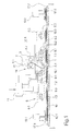
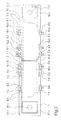
- FIG. 1 and 2 an embodiment of the device according to the invention for carrying out the method according to the invention for depositing a flexible material web is shown in several views.
- Fig. 1 shows the embodiment schematically in a cross-sectional view and in Fig. 2 the embodiment is shown in a plan view. Unless an explicit reference is made to one of the figures, the following description applies to both figures.
- the deposit location for receiving a material web 2 into a plurality of deposited material layers 16 is formed by a storage station 1.
- the storage station 1 can be formed for example by a height-adjustable storage table.
- the storage station 1 extends over a laying length between two ends 17.1 and 17.2.
- the laying length of the storage station 1 is in this case significantly larger than a depositing width, which are determined by two opposite longitudinal sides 18.1 and 18.2 of the storage station.
- the storage station 1 is associated with a stationary feeder 3 in the central region.
- the feeding device 3 is held above the depositing station 1 and has two conveying rollers 4.1 and 4.2, which form a conveying nip as a pair of rollers, in which the material web 2 is fed.
- One of the feed rollers 4.1 or 4.2 is connected to a drive.
- a laying device 5 is provided between the storage station and the feeder 3, to deposit the supplied material web 2 zig-zag to form several layers of material in the storage station.
- the laying device 5 has two blowing devices 6.1 and 6.2 in order to alternately produce a directed in a deposition direction blowing.
- the blowing device 6.1 a total of three air nozzles 7.1, 7.2 and 7.3.
- the air nozzles 7.1 to 7.3 are arranged distributed on the longitudinal side 18.1 in the area between the feed device 3 and the end 17.1 of the storage station 1 at a distance from each other.
- a first air nozzle 7.1 is held immediately below the conveyor rollers 4.1 and 4.2.
- the second air nozzle 7.2 and the third air nozzle 7.3 are arranged on the longitudinal side 18.1 until shortly before the end 17.1 of the storage station 1.
- Each of the air nozzles 7.1, 7.2 and 7.3 have an identical blowing direction, which in this case defines the storage direction towards the end 17.1 of the storage station 1.
- Each air nozzles 7.1 to 7.3 are each assigned a control valve 9.1 to 9.3.
- the control valves 9.1 to 9.3 are connected via a control line to a control device 11.
- each of the control valves 9.1 to 9.3 for activating and deactivating the air nozzles 7.1 to 7.3 can be controlled separately.
- the air nozzles 7.1 to 7.3 are connected to a compressed air source, not shown here.
- Each of the air nozzles 7.4 to 7.6 is also associated with a control valve 9.4 to 9.6.
- the control valves 9.4 to 9.6 are coupled to the control device 11, which is not shown in detail at this point.
- the air nozzles 7.4 to 7.6 also have a blowing direction, which is directed in the direction of deposit to the end 17.1 of the storage station 1.
- the air nozzles 7.1 to 7.6 connected to a pressure source are aligned in such a way that the blowing is directed onto the material web 2 guided between the air nozzles.
- the directly opposite air nozzles 7.1 and 7.4 or 7.2 and 7.5 or 7.3 and 7.6 synchronously activated or deactivated as an air nozzle pair.
- the respective control valves 9.1 and 9.4 are controlled synchronously.
- a second blowing device 6.2 is provided in order to guide the material web 2 for depositing in the opposite direction of deposition to the opposite end 17. 2 of the deposition station 1.
- the blowing device 6.2 three air nozzles 8.1 to 8.3, which are arranged distributed on the longitudinal side 18.1.
- a first air nozzle 8.1 is held between the air nozzles 7.1 and 7.2 of the first blowing device 6.1.
- the air nozzles 8.2 and 8.3 are arranged distributed on the longitudinal side 18.2 between the end 17.2 and the feeder 3.
- Each of the air nozzles 8.1 to 8.3 has a directed towards the end of 17.2 blowing direction and thus forms an opposite Anblasung for guiding and storage of the web 2 to the opposite end 17.2 of the storage station 1.
- Each of the air nozzles 8.1 to 8.3 is a separate control valve 10.1 to 10.3 connected to a pressure source.
- the control valves 10.1 to 10.3 are connected via control lines to the control device 11 and independently controllable.
- the second blowing device 6.2 is also formed by further air nozzles 8.4 to 8.6 on the opposite longitudinal side 18.2 of the storage station 1.
- the air nozzles 8.4 to 8.6 each form a plurality of pairs of air nozzles with the air nozzles 8.1 to 8.3, which are activated and deactivated synchronously via their associated control valves 10.1 to 10.6.
- the air nozzles 8.1 to 8.6 are aligned on the longitudinal sides 18.1 and 18.2 of the deposition station such that the blowing produced by the blowing device 6.2 is directed directly onto the material web 2 guided between the longitudinal sides 18.1 and 18.2.
- the air nozzles 7.1 to 7.6 of the first blowing device 6.1 and the air nozzles 8.1 to 8.6 of the second blowing device 6.2 are preferred supplies a common compressed air source. However, there is also the possibility that each blowing device 6.1 and 6.2 are assigned separate sources of compressed air.
- the control device 11 is coupled to a sensor device 14.
- the sensor device 14 is formed in this embodiment by a speed sensor 15 which is assigned to the driven conveyor roller 4.1.
- the speed sensor 15 the drive speed of the feed roller 4.1 and the peripheral speed of the feed roller 4.1 is detected and transmitted to the controller 11.
- the controller 11 it is thus possible to determine an added material length of the material web 2 from the actual feed speed of the material web 2, so that its position can be determined over the length of the material web 2 fed into the intermediate space between the feed device 3 and the deposition station 1. From this, a time sequence can then be derived in order to control the activation and deactivation of the individual air nozzles 7.1 to 7.6 and 87.1 to 8.6 of the blowing devices 6.1 and 6.2.
- each of the ends 17.1 and 17.2 is assigned a hold-down 12.1 and 12.2.
- the hold-down 12.1 and 12.2 are plate-shaped and driven by an actuator 13.1 and 13.2 movable.
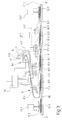
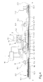
- Fig. 3 and 4 is the embodiment of Fig. 1 shown in different operating conditions for storing the material web 2.
- the web 2 fed by the feeder 3 continuously the storage station 1.
- the first air nozzle 7.1 or the first pair of air nozzles 7.1 and 7.4 via the control device 11 activated.
- the generated blow is directed to the web 2 and leads them in a first storage direction to the end of 17.1.
- the material web 2 deposits on the deposition station 1 or the topmost material layer 16.
- the adjacent air nozzle 7.2 or the adjacent air nozzle pair 7.2 and 7.5 these are activated.
- the blowing effect of the first blowing device 6.1 is maintained and guides the material web 2 continuously up to the end 17.1 of the deposition station 1.
- the material web 2 is folded and smoothed by the holding-down device 12.1, so that a new material layer 16 can be produced by guiding the material web 2 in the opposite depositing direction.
- the first blowing device 6.1 is deactivated so that the material web 2 deposits itself automatically in the section between the end 17.1 of the deposition station and the feed device 3.
- a second blowing is generated in an opposite direction of deposit to the opposite end 17.2. This process is in Fig. 4 shown.
- blowing device 6.2 is activated to guide the web to the opposite end 17.2.
- the air nozzles 8.1 to 8.6 or the air nozzle pairs of the blowing device 6.2 are also activated according to a time sequence which is predetermined by the control device 11 as a function of the feed speed of the material web 2.
- the material web 2 settles to a new material layer, and is folded at the opposite end 17.2 by the second hold-down 12.2, smoothed and fixed.
- the inventive method and the device according to the invention are not limited to the illustrated and described embodiment.
- the number of air nozzles for guiding the material web in a depositing direction depends in particular on the length of the filing path.
- additional air nozzles can be added.
- the feeding of the material web could also take place at one end of the deposition station, so that only one of the blowing devices would be formed by a plurality of air nozzles distributed on the longitudinal sides.
- control device In order to activate the air nozzles, the control device is preferably given a chronological start-up sequence that is tuned to a specific feed speed of the material web. Thus, even without continuous monitoring of the feed rate make fixed settings that ensure safe storage of the web of the storage station.
- the sensor device is formed by position sensors which are arranged distributed along one of the longitudinal sides.
- the method variant is carried out, in which the feed rate is monitored by a speed sensor.
- the power-on sequences for activating and deactivating the air nozzles of the blowing devices can be controlled.
- the storage stations are preferably coupled to a drive, which executes a movement between two end positions transversely directed for receiving the material layers.
- a drive which executes a movement between two end positions transversely directed for receiving the material layers.
- This can also be advantageous square material stacks are laid in which the storage length is equal to a storage width.
Landscapes
- Preliminary Treatment Of Fibers (AREA)
- Folding Of Thin Sheet-Like Materials, Special Discharging Devices, And Others (AREA)
Claims (17)
- Procédé pour déposer une bande de matière souple (2) en plusieurs couches de matière superposées (16), dans lequel la bande de matière (2) est acheminée à une zone de dépose, dans lequel la bande de matière (2) est guidée suivant un mouvement de va-et-vient par une première insufflation dans une première direction de dépose vers une extrémité (17.1, 17.2) de la zone de dépose et par une deuxième insufflation dans une deuxième direction de dépose vers une extrémité opposée (17.2, 17.1) de la zone de dépose, et dans lequel les insufflations sont produites par plusieurs buses à air activées en alternance (7.1 ... 7.6 ; 8.1 ... 8.6),
caractérisé en ce
qu'au moins l'une des insufflations est produite par plusieurs buses à air (7.1 ... 7.6 ; 8.1 ... 8.6) activées les unes après les autres, lesquelles soufflent dans l'une des directions de dépose. - Procédé selon la revendication 1,
caractérisé en ce que
la bande de matériau (2) est acheminée dans une région centrale de la zone de dépose et en ce que les insufflations opposées sont également produites par plusieurs buses à air (7.1 ... 7.6 ; 8.1 ... 8.6) activées les unes après les autres, qui soufflent dans la direction de dépose opposée. - Procédé selon la revendication 1 ou 2,
caractérisé en ce que
les buses à air (7.1 ... 7.6 ; 8.1 ... 8.6) sont activées pour produire l'une des insufflations en fonction d'une position de la bande de matière entre les extrémités de la zone de dépose. - Procédé selon la revendication 3,
caractérisé en ce que
les buses à air (7.1 ... 7.6 ; 8.1 ... 8.6) sont activées en fonction d'une séquence d'enclenchement temporelle qui est déterminée en fonction d'une vitesse d'amenée de la bande de matière (2). - Procédé selon la revendication 4,
caractérisé en ce que
la vitesse d'amenée de la bande de matière (2) est déterminée à partir d'une vitesse périphérique d'un rouleau de transport (4.1, 4.2), par lequel rouleau de transport (4.1, 4.2) la bande de matière est acheminée. - Procédé selon l'une quelconque des revendications 1 à 5,
caractérisé en ce que
les insufflations sont produites par plusieurs buses à air (7.1 ... 7.6 ; 8.1 ... 8.6) opposées au niveau de deux côtés longitudinaux de la zone de dépose. - Procédé selon la revendication 6,
caractérisé en ce que
les buses à air (7.1 ... 7.6 ; 8.1 ... 8.6) directement opposées au niveau des côtés longitudinaux forment une paire de buses à air (7.1, 7.4 ; 7.2, 7.5 ; 7.3, 7.6 ; 8.1, 8.4 ; 8.2, 8.5 ; 8.3, 8.6) et sont activées et désactivées de manière synchronisée. - Procédé selon l'une quelconque des revendications 1 à 7,
caractérisé en ce que
les couches de matière (16) au niveau des extrémités de la zone de dépose sont lissées et retenues par deux éléments mobiles de maintien vers le bas (12.1, 12.2). - Dispositif pour mettre en oeuvre le procédé selon l'une quelconque des revendications 1 à 8, comprenant un poste de dépose (1) pour recevoir plusieurs couches de matière (16) superposées, comprenant un dispositif d'amenée (3) associé au poste de dépose (1) pour acheminer une bande de matière (2) et comprenant un dispositif de pose (5) pour déposer la bande de matière (2) dans le poste de dépose (1), le dispositif de pose (5) présentant deux dispositifs de soufflage (6.1, 6.2) comprenant plusieurs buses à air (9.1, 10.1), qui produisent en alternance une première insufflation dans une première direction de dépose et un deuxième insufflation dans une deuxième direction de dépose opposée,
caractérisé en ce
qu'au moins l'un des dispositifs de soufflage (6.1) présente plusieurs buses à air (7.1 - 7.3) disposées le long de l'une des directions de dépose, lesquelles sont orientées chacune dans la direction de dépose et peuvent être activées les unes après les autres. - Dispositif selon la revendication 9,
caractérisé en ce que
le dispositif d'amenée (3) est disposé dans une région centrale du poste de dépose (1) et en ce que le deuxième dispositif de soufflage (6.2) présente plusieurs buses à air (8.1 - 8.3) disposées le long des deuxièmes directions de dépose, lesquelles sont orientées à chaque fois dans la direction de dépose et peuvent être activées les unes après les autres. - Dispositif selon l'une quelconque des revendications 9 ou 10,
caractérisé en ce
qu'une soupape de commande (9.1 - 9.3) est à chaque fois associée aux buses à air (7.1 - 7.3), lesquelles soupapes de commande sont connectées à un dispositif de commande (11) et peuvent être commandées indépendamment les unes des autres pour activer les buses à air (7.1 - 7.3). - Dispositif selon la revendication 11,
caractérisé en ce que
le dispositif de commande (11) est connecté à un dispositif de capteur (14) qui permet de détecter directement ou indirectement une position instantanée de la bande de matière (2) entre les extrémités (17.1, 17.2) du poste de dépose (1). - Dispositif selon la revendication 12,
caractérisé en ce que
le dispositif de capteur (14) présente un capteur de vitesse de rotation (15) qui est associé au dispositif d'amenée (3) pour détecter la vitesse périphérique d'un rouleau de transport (4.1). - Dispositif selon l'une quelconque des revendications 9 à 13,
caractérisé en ce que
le dispositif d'amenée (3) est formé par une paire de rouleaux (4.1, 4.2), dont les rouleaux de transport (4.1, 4.2) sont opposés dans une fente de transport, au moins l'un des rouleaux de transport (4.1) étant entraînable. - Dispositif selon l'une quelconque des revendications 9 à 14,
caractérisé en ce
qu'au moins l'un des dispositifs de soufflage (6.1, 6.2) présente plusieurs buses à air (7.1, 7.6, 8.1 - 8.6) réparties sur les deux côtés longitudinaux (18.1, 18.2) du poste de dépose (1). - Dispositif selon la revendication 15,
caractérisé en ce que
des buses à air (7.1, 7.4 ; 8.1, 8.4) directement opposées au niveau des côtés longitudinaux (18.1, 18.2) du poste de dépose (1) forment une paire de buses à air, dont les soupapes de commande associées (9.1, 9.4, 10.1, 10.4) peuvent être commandées de manière synchronisée. - Dispositif selon l'une quelconque des revendications 9 à 16,
caractérisé en ce
qu'à chaque extrémité (17.1, 17.2) du poste de dépose (1) est disposé un élément de maintien vers le bas (12.1, 12.2) déplaçable séparé, qui peut être entraîné par le biais d'actionneurs (13.1, 13.2) pour le lissage et le maintien des couches de matière (16).
Applications Claiming Priority (2)
| Application Number | Priority Date | Filing Date | Title |
|---|---|---|---|
| DE102009038089 | 2009-08-19 | ||
| PCT/EP2010/061455 WO2011020709A1 (fr) | 2009-08-19 | 2010-08-05 | Procédé et dispositif pour déposer une bande de matière souple |
Publications (2)
| Publication Number | Publication Date |
|---|---|
| EP2467324A1 EP2467324A1 (fr) | 2012-06-27 |
| EP2467324B1 true EP2467324B1 (fr) | 2014-01-08 |
Family
ID=42935563
Family Applications (1)
| Application Number | Title | Priority Date | Filing Date |
|---|---|---|---|
| EP10740642.3A Not-in-force EP2467324B1 (fr) | 2009-08-19 | 2010-08-05 | Procédé et dispositif pour déposer une bande de matière souple |
Country Status (4)
| Country | Link |
|---|---|
| EP (1) | EP2467324B1 (fr) |
| CN (1) | CN102471005B (fr) |
| DK (1) | DK2467324T3 (fr) |
| WO (1) | WO2011020709A1 (fr) |
Families Citing this family (2)
| Publication number | Priority date | Publication date | Assignee | Title |
|---|---|---|---|---|
| JP6281532B2 (ja) * | 2015-07-13 | 2018-02-21 | トヨタ自動車株式会社 | 金属空気電池用電解液、及び、金属空気電池 |
| CN118773826B (zh) * | 2024-06-25 | 2025-09-05 | 晋江市聚嘉环保科技有限公司 | 一种气凝胶喷胶棉及其生产用的铺网机 |
Family Cites Families (8)
| Publication number | Priority date | Publication date | Assignee | Title |
|---|---|---|---|---|
| DE1180236B (de) * | 1962-06-27 | 1964-10-22 | Warner Jones And Company Ltd K | Vorrichtung zum Falten von abschnittsweise mit querverlaufenden Schwaechungslinien versehenen Bahnen aus Papier, Kunststoff od. dgl. |
| DE2712588C2 (de) * | 1977-03-22 | 1983-12-08 | Siemens AG, 1000 Berlin und 8000 München | Einlegevorrichtung für eine vorgefaltete Endlospapierbahn in einem Papierstapler |
| US4279610A (en) * | 1979-10-22 | 1981-07-21 | Crown Zellerbach Corporation | Cross-lapped web forming system |
| DE3001729A1 (de) * | 1980-01-18 | 1981-07-23 | Krauss U. Reichert Gmbh + Co Kg Spezialmaschinenfabrik, 7012 Fellbach | Stofflegemaschine |
| US4460350A (en) | 1980-09-02 | 1984-07-17 | Sperry Corporation | Continuous printed paper stacking device |
| DE102005016745A1 (de) * | 2005-04-11 | 2006-10-12 | Saurer Gmbh & Co. Kg | Verfahren und Vorrichtung zum Ablegen einer flexiblen Materialbahn |
| DE102005016754B4 (de) | 2005-04-11 | 2012-12-27 | Nis Ingenieurgesellschaft Mbh | Verfahren zum Entwässern von Substanzen |
| CN201287991Y (zh) * | 2008-08-07 | 2009-08-12 | 邯郸纺织机械有限公司 | 一种折布平衡机构 |
-
2010
- 2010-08-05 EP EP10740642.3A patent/EP2467324B1/fr not_active Not-in-force
- 2010-08-05 WO PCT/EP2010/061455 patent/WO2011020709A1/fr not_active Ceased
- 2010-08-05 DK DK10740642.3T patent/DK2467324T3/da active
- 2010-08-05 CN CN201080036530.1A patent/CN102471005B/zh not_active Expired - Fee Related
Also Published As
| Publication number | Publication date |
|---|---|
| DK2467324T3 (da) | 2014-04-07 |
| CN102471005B (zh) | 2014-09-24 |
| EP2467324A1 (fr) | 2012-06-27 |
| WO2011020709A1 (fr) | 2011-02-24 |
| CN102471005A (zh) | 2012-05-23 |
Similar Documents
| Publication | Publication Date | Title |
|---|---|---|
| DE2512922C2 (de) | Vorrichtung zur Reinigung eines umlaufenden Filztuches | |
| EP2918719B1 (fr) | Procédé d'homogénéisation de l'image de piqûre dans une étoffe aiguilletée | |
| WO1998055313A1 (fr) | Procede pour la separation transversale d'une bande de papier en defilement | |
| EP3377308A1 (fr) | Installation de fabrication pour poser des bandes de fibres | |
| DE10052015A1 (de) | Bewegbarer Falzapparat und Falztrichteranordnung | |
| EP3025994B1 (fr) | Dispositif et procédé de fabrication de paquets empilés de feuilles imprimées | |
| EP2157216A1 (fr) | Dispositif destiné à la pose d'un voile | |
| DE4328461A1 (de) | Verfahren und Anordnung zum Fördern flächiger Werkstücke | |
| DE10036821B4 (de) | Vorrichtung zum Mustern einer Filzbahn durch ein Nadeln mit einer Nadelungseinrichtung | |
| DE4202363C2 (de) | Vorrichtung zum Trennen einer auch aus mehreren Teilbahnen bestehenden Bahn in Abschnitte | |
| DE2428113A1 (de) | Vorrichtung zum kantengeraden aufwickeln von warenbahnen | |
| EP2361865A1 (fr) | Procédé et dispositif de formation de piles à partir d'un flux de produits d'impression en formation imbriquée | |
| EP2409939B1 (fr) | Installation de pliage et d'agrafage pour bandes de carton ondulé | |
| EP2467324A1 (fr) | Procédé et dispositif pour déposer une bande de matière souple | |
| DE102011001835A1 (de) | Verfahren und Vorrichtung zur Verarbeitung eines Bandes | |
| DE102010001899B4 (de) | Vorrichtung und Verfahren zum Binden von Stapeln von Lagen, insbesondere für die Herstellung von sicherheitsrelevanten Dokumenten | |
| EP0723862A1 (fr) | Procédé et dispositif d'engagement d'une bande imprimée | |
| EP3369663B1 (fr) | Dispositif de bottelage pour pièces à usiner oblongues ainsi que procédé de bottelage de pièces à usiner oblongues | |
| DE2653790A1 (de) | Verfahren und vorrichtung zum lagenlegen von karostoffen | |
| DE2208756C3 (de) | Spannmaschine für Warenbahnen | |
| DE102013013534A1 (de) | Schnittbogenlängenkontrolle in Trockenenden von Wellpappenmaschine | |
| EP2635729B1 (fr) | Dispositif de depot de bande de non-tisse et procede pour former un non-tisse | |
| DE102011001464B4 (de) | Verfahren und Vorrichtung zur Injektion von Flüssigkeit in Lebensmittelprodukte | |
| AT248996B (de) | Vorrichtung zum Herstellen von Bouclé- oder Velourteppichen | |
| DE202014010628U1 (de) | Vorrichtung zum Herstellen von Stapelpaketen |
Legal Events
| Date | Code | Title | Description |
|---|---|---|---|
| PUAI | Public reference made under article 153(3) epc to a published international application that has entered the european phase |
Free format text: ORIGINAL CODE: 0009012 |
|
| 17P | Request for examination filed |
Effective date: 20120106 |
|
| AK | Designated contracting states |
Kind code of ref document: A1 Designated state(s): AL AT BE BG CH CY CZ DE DK EE ES FI FR GB GR HR HU IE IS IT LI LT LU LV MC MK MT NL NO PL PT RO SE SI SK SM TR |
|
| DAX | Request for extension of the european patent (deleted) | ||
| GRAP | Despatch of communication of intention to grant a patent |
Free format text: ORIGINAL CODE: EPIDOSNIGR1 |
|
| INTG | Intention to grant announced |
Effective date: 20131003 |
|
| GRAS | Grant fee paid |
Free format text: ORIGINAL CODE: EPIDOSNIGR3 |
|
| GRAA | (expected) grant |
Free format text: ORIGINAL CODE: 0009210 |
|
| AK | Designated contracting states |
Kind code of ref document: B1 Designated state(s): AL AT BE BG CH CY CZ DE DK EE ES FI FR GB GR HR HU IE IS IT LI LT LU LV MC MK MT NL NO PL PT RO SE SI SK SM TR |
|
| REG | Reference to a national code |
Ref country code: GB Ref legal event code: FG4D Free format text: NOT ENGLISH |
|
| REG | Reference to a national code |
Ref country code: CH Ref legal event code: EP |
|
| REG | Reference to a national code |
Ref country code: IE Ref legal event code: FG4D Free format text: LANGUAGE OF EP DOCUMENT: GERMAN |
|
| REG | Reference to a national code |
Ref country code: AT Ref legal event code: REF Ref document number: 648599 Country of ref document: AT Kind code of ref document: T Effective date: 20140215 |
|
| REG | Reference to a national code |
Ref country code: DE Ref legal event code: R096 Ref document number: 502010005904 Country of ref document: DE Effective date: 20140220 |
|
| REG | Reference to a national code |
Ref country code: DK Ref legal event code: T3 Effective date: 20140404 |
|
| REG | Reference to a national code |
Ref country code: SE Ref legal event code: TRGR |
|
| REG | Reference to a national code |
Ref country code: NL Ref legal event code: VDEP Effective date: 20140108 |
|
| REG | Reference to a national code |
Ref country code: LT Ref legal event code: MG4D |
|
| PG25 | Lapsed in a contracting state [announced via postgrant information from national office to epo] |
Ref country code: LT Free format text: LAPSE BECAUSE OF FAILURE TO SUBMIT A TRANSLATION OF THE DESCRIPTION OR TO PAY THE FEE WITHIN THE PRESCRIBED TIME-LIMIT Effective date: 20140108 Ref country code: NO Free format text: LAPSE BECAUSE OF FAILURE TO SUBMIT A TRANSLATION OF THE DESCRIPTION OR TO PAY THE FEE WITHIN THE PRESCRIBED TIME-LIMIT Effective date: 20140408 Ref country code: IS Free format text: LAPSE BECAUSE OF FAILURE TO SUBMIT A TRANSLATION OF THE DESCRIPTION OR TO PAY THE FEE WITHIN THE PRESCRIBED TIME-LIMIT Effective date: 20140508 |
|
| PG25 | Lapsed in a contracting state [announced via postgrant information from national office to epo] |
Ref country code: PT Free format text: LAPSE BECAUSE OF FAILURE TO SUBMIT A TRANSLATION OF THE DESCRIPTION OR TO PAY THE FEE WITHIN THE PRESCRIBED TIME-LIMIT Effective date: 20140508 Ref country code: ES Free format text: LAPSE BECAUSE OF FAILURE TO SUBMIT A TRANSLATION OF THE DESCRIPTION OR TO PAY THE FEE WITHIN THE PRESCRIBED TIME-LIMIT Effective date: 20140108 Ref country code: CY Free format text: LAPSE BECAUSE OF FAILURE TO SUBMIT A TRANSLATION OF THE DESCRIPTION OR TO PAY THE FEE WITHIN THE PRESCRIBED TIME-LIMIT Effective date: 20140108 Ref country code: NL Free format text: LAPSE BECAUSE OF FAILURE TO SUBMIT A TRANSLATION OF THE DESCRIPTION OR TO PAY THE FEE WITHIN THE PRESCRIBED TIME-LIMIT Effective date: 20140108 Ref country code: FI Free format text: LAPSE BECAUSE OF FAILURE TO SUBMIT A TRANSLATION OF THE DESCRIPTION OR TO PAY THE FEE WITHIN THE PRESCRIBED TIME-LIMIT Effective date: 20140108 |
|
| PG25 | Lapsed in a contracting state [announced via postgrant information from national office to epo] |
Ref country code: HR Free format text: LAPSE BECAUSE OF FAILURE TO SUBMIT A TRANSLATION OF THE DESCRIPTION OR TO PAY THE FEE WITHIN THE PRESCRIBED TIME-LIMIT Effective date: 20140108 Ref country code: LV Free format text: LAPSE BECAUSE OF FAILURE TO SUBMIT A TRANSLATION OF THE DESCRIPTION OR TO PAY THE FEE WITHIN THE PRESCRIBED TIME-LIMIT Effective date: 20140108 |
|
| REG | Reference to a national code |
Ref country code: DE Ref legal event code: R097 Ref document number: 502010005904 Country of ref document: DE |
|
| PG25 | Lapsed in a contracting state [announced via postgrant information from national office to epo] |
Ref country code: RO Free format text: LAPSE BECAUSE OF FAILURE TO SUBMIT A TRANSLATION OF THE DESCRIPTION OR TO PAY THE FEE WITHIN THE PRESCRIBED TIME-LIMIT Effective date: 20140108 Ref country code: EE Free format text: LAPSE BECAUSE OF FAILURE TO SUBMIT A TRANSLATION OF THE DESCRIPTION OR TO PAY THE FEE WITHIN THE PRESCRIBED TIME-LIMIT Effective date: 20140108 Ref country code: CZ Free format text: LAPSE BECAUSE OF FAILURE TO SUBMIT A TRANSLATION OF THE DESCRIPTION OR TO PAY THE FEE WITHIN THE PRESCRIBED TIME-LIMIT Effective date: 20140108 |
|
| PLBE | No opposition filed within time limit |
Free format text: ORIGINAL CODE: 0009261 |
|
| STAA | Information on the status of an ep patent application or granted ep patent |
Free format text: STATUS: NO OPPOSITION FILED WITHIN TIME LIMIT |
|
| PG25 | Lapsed in a contracting state [announced via postgrant information from national office to epo] |
Ref country code: PL Free format text: LAPSE BECAUSE OF FAILURE TO SUBMIT A TRANSLATION OF THE DESCRIPTION OR TO PAY THE FEE WITHIN THE PRESCRIBED TIME-LIMIT Effective date: 20140108 Ref country code: SK Free format text: LAPSE BECAUSE OF FAILURE TO SUBMIT A TRANSLATION OF THE DESCRIPTION OR TO PAY THE FEE WITHIN THE PRESCRIBED TIME-LIMIT Effective date: 20140108 |
|
| 26N | No opposition filed |
Effective date: 20141009 |
|
| REG | Reference to a national code |
Ref country code: DE Ref legal event code: R097 Ref document number: 502010005904 Country of ref document: DE Effective date: 20141009 |
|
| PG25 | Lapsed in a contracting state [announced via postgrant information from national office to epo] |
Ref country code: LU Free format text: LAPSE BECAUSE OF FAILURE TO SUBMIT A TRANSLATION OF THE DESCRIPTION OR TO PAY THE FEE WITHIN THE PRESCRIBED TIME-LIMIT Effective date: 20140805 Ref country code: MC Free format text: LAPSE BECAUSE OF FAILURE TO SUBMIT A TRANSLATION OF THE DESCRIPTION OR TO PAY THE FEE WITHIN THE PRESCRIBED TIME-LIMIT Effective date: 20140108 |
|
| GBPC | Gb: european patent ceased through non-payment of renewal fee |
Effective date: 20140805 |
|
| PG25 | Lapsed in a contracting state [announced via postgrant information from national office to epo] |
Ref country code: BE Free format text: LAPSE BECAUSE OF NON-PAYMENT OF DUE FEES Effective date: 20140831 |
|
| REG | Reference to a national code |
Ref country code: IE Ref legal event code: MM4A |
|
| PG25 | Lapsed in a contracting state [announced via postgrant information from national office to epo] |
Ref country code: SI Free format text: LAPSE BECAUSE OF FAILURE TO SUBMIT A TRANSLATION OF THE DESCRIPTION OR TO PAY THE FEE WITHIN THE PRESCRIBED TIME-LIMIT Effective date: 20140108 |
|
| PG25 | Lapsed in a contracting state [announced via postgrant information from national office to epo] |
Ref country code: GB Free format text: LAPSE BECAUSE OF NON-PAYMENT OF DUE FEES Effective date: 20140805 |
|
| REG | Reference to a national code |
Ref country code: FR Ref legal event code: PLFP Year of fee payment: 6 |
|
| PG25 | Lapsed in a contracting state [announced via postgrant information from national office to epo] |
Ref country code: IE Free format text: LAPSE BECAUSE OF NON-PAYMENT OF DUE FEES Effective date: 20140805 |
|
| PGFP | Annual fee paid to national office [announced via postgrant information from national office to epo] |
Ref country code: DE Payment date: 20150824 Year of fee payment: 6 Ref country code: DK Payment date: 20150824 Year of fee payment: 6 Ref country code: CH Payment date: 20150824 Year of fee payment: 6 |
|
| PGFP | Annual fee paid to national office [announced via postgrant information from national office to epo] |
Ref country code: FR Payment date: 20150824 Year of fee payment: 6 Ref country code: SE Payment date: 20150824 Year of fee payment: 6 |
|
| PGFP | Annual fee paid to national office [announced via postgrant information from national office to epo] |
Ref country code: IT Payment date: 20150831 Year of fee payment: 6 |
|
| PG25 | Lapsed in a contracting state [announced via postgrant information from national office to epo] |
Ref country code: SM Free format text: LAPSE BECAUSE OF FAILURE TO SUBMIT A TRANSLATION OF THE DESCRIPTION OR TO PAY THE FEE WITHIN THE PRESCRIBED TIME-LIMIT Effective date: 20140108 |
|
| PG25 | Lapsed in a contracting state [announced via postgrant information from national office to epo] |
Ref country code: MT Free format text: LAPSE BECAUSE OF FAILURE TO SUBMIT A TRANSLATION OF THE DESCRIPTION OR TO PAY THE FEE WITHIN THE PRESCRIBED TIME-LIMIT Effective date: 20140108 Ref country code: GR Free format text: LAPSE BECAUSE OF FAILURE TO SUBMIT A TRANSLATION OF THE DESCRIPTION OR TO PAY THE FEE WITHIN THE PRESCRIBED TIME-LIMIT Effective date: 20140409 Ref country code: BG Free format text: LAPSE BECAUSE OF FAILURE TO SUBMIT A TRANSLATION OF THE DESCRIPTION OR TO PAY THE FEE WITHIN THE PRESCRIBED TIME-LIMIT Effective date: 20140108 |
|
| PG25 | Lapsed in a contracting state [announced via postgrant information from national office to epo] |
Ref country code: TR Free format text: LAPSE BECAUSE OF FAILURE TO SUBMIT A TRANSLATION OF THE DESCRIPTION OR TO PAY THE FEE WITHIN THE PRESCRIBED TIME-LIMIT Effective date: 20140108 Ref country code: HU Free format text: LAPSE BECAUSE OF FAILURE TO SUBMIT A TRANSLATION OF THE DESCRIPTION OR TO PAY THE FEE WITHIN THE PRESCRIBED TIME-LIMIT; INVALID AB INITIO Effective date: 20100805 |
|
| REG | Reference to a national code |
Ref country code: AT Ref legal event code: MM01 Ref document number: 648599 Country of ref document: AT Kind code of ref document: T Effective date: 20150805 |
|
| PG25 | Lapsed in a contracting state [announced via postgrant information from national office to epo] |
Ref country code: AT Free format text: LAPSE BECAUSE OF NON-PAYMENT OF DUE FEES Effective date: 20150805 |
|
| REG | Reference to a national code |
Ref country code: DE Ref legal event code: R119 Ref document number: 502010005904 Country of ref document: DE |
|
| REG | Reference to a national code |
Ref country code: DK Ref legal event code: EBP Effective date: 20160831 |
|
| REG | Reference to a national code |
Ref country code: SE Ref legal event code: EUG |
|
| REG | Reference to a national code |
Ref country code: CH Ref legal event code: PL |
|
| PG25 | Lapsed in a contracting state [announced via postgrant information from national office to epo] |
Ref country code: LI Free format text: LAPSE BECAUSE OF NON-PAYMENT OF DUE FEES Effective date: 20160831 Ref country code: CH Free format text: LAPSE BECAUSE OF NON-PAYMENT OF DUE FEES Effective date: 20160831 Ref country code: SE Free format text: LAPSE BECAUSE OF NON-PAYMENT OF DUE FEES Effective date: 20160806 |
|
| REG | Reference to a national code |
Ref country code: FR Ref legal event code: ST Effective date: 20170428 |
|
| PG25 | Lapsed in a contracting state [announced via postgrant information from national office to epo] |
Ref country code: FR Free format text: LAPSE BECAUSE OF NON-PAYMENT OF DUE FEES Effective date: 20160831 Ref country code: DK Free format text: LAPSE BECAUSE OF NON-PAYMENT OF DUE FEES Effective date: 20160831 Ref country code: DE Free format text: LAPSE BECAUSE OF NON-PAYMENT OF DUE FEES Effective date: 20170301 |
|
| PG25 | Lapsed in a contracting state [announced via postgrant information from national office to epo] |
Ref country code: IT Free format text: LAPSE BECAUSE OF NON-PAYMENT OF DUE FEES Effective date: 20160805 |
|
| PG25 | Lapsed in a contracting state [announced via postgrant information from national office to epo] |
Ref country code: MK Free format text: LAPSE BECAUSE OF FAILURE TO SUBMIT A TRANSLATION OF THE DESCRIPTION OR TO PAY THE FEE WITHIN THE PRESCRIBED TIME-LIMIT Effective date: 20140108 |
|
| PG25 | Lapsed in a contracting state [announced via postgrant information from national office to epo] |
Ref country code: AL Free format text: LAPSE BECAUSE OF FAILURE TO SUBMIT A TRANSLATION OF THE DESCRIPTION OR TO PAY THE FEE WITHIN THE PRESCRIBED TIME-LIMIT Effective date: 20140108 |