EP2468146A1 - Meuble d'exposition réfrigéré - Google Patents
Meuble d'exposition réfrigéré Download PDFInfo
- Publication number
- EP2468146A1 EP2468146A1 EP11009689A EP11009689A EP2468146A1 EP 2468146 A1 EP2468146 A1 EP 2468146A1 EP 11009689 A EP11009689 A EP 11009689A EP 11009689 A EP11009689 A EP 11009689A EP 2468146 A1 EP2468146 A1 EP 2468146A1
- Authority
- EP
- European Patent Office
- Prior art keywords
- handle
- support surface
- goods support
- insert according
- counter insert
- Prior art date
- Legal status (The legal status is an assumption and is not a legal conclusion. Google has not performed a legal analysis and makes no representation as to the accuracy of the status listed.)
- Granted
Links
Images


Classifications
-
- A—HUMAN NECESSITIES
- A47—FURNITURE; DOMESTIC ARTICLES OR APPLIANCES; COFFEE MILLS; SPICE MILLS; SUCTION CLEANERS IN GENERAL
- A47F—SPECIAL FURNITURE, FITTINGS, OR ACCESSORIES FOR SHOPS, STOREHOUSES, BARS, RESTAURANTS OR THE LIKE; PAYING COUNTERS
- A47F3/00—Show cases or show cabinets
- A47F3/04—Show cases or show cabinets air-conditioned, refrigerated
- A47F3/0482—Details common to both closed and open types
- A47F3/0486—Details common to both closed and open types for charging, displaying or discharging the articles
-
- A—HUMAN NECESSITIES
- A47—FURNITURE; DOMESTIC ARTICLES OR APPLIANCES; COFFEE MILLS; SPICE MILLS; SUCTION CLEANERS IN GENERAL
- A47F—SPECIAL FURNITURE, FITTINGS, OR ACCESSORIES FOR SHOPS, STOREHOUSES, BARS, RESTAURANTS OR THE LIKE; PAYING COUNTERS
- A47F3/00—Show cases or show cabinets
- A47F3/06—Show cases or show cabinets with movable or removable shelves or receptacles
Definitions
- the preceding invention relates to a counter insert according to the preamble of claim 1.
- a generic counter insert in particular a refrigerated counter insert, has a tilt-adjustable goods support surface and a handle for lifting at least the goods support surface in an inclined position.
- Another generic counter insert is in DE 100 64 633 A1 described.
- a projection is provided on a trough of the counter insert and on the goods support surface a flexible support is provided, which is supported on the projection.
- an object of the invention can be considered to provide a counter insert whose Painauflage Materials is movable and sustainable in a particularly simple operation in different inclination positions.
- the handle for holding the goods support surface in the inclined position, the handle is movable into a support position in which the handle is supported on a stationary part, and in that a spring device is in operative connection with the handle, which moves the handle in the inclined position automatically in the support position.
- the handle is designed to be movable relative to the goods support surface.
- the spring device itself is not supported on the fixed part. Rather, according to the invention, the spring device is completely gripped in an operating position. That is, the spring means press against an inner wall of the handle, not against a fixed part, in particular not a fixed part of a trough of the counter insert.
- a fixed part is to be understood as meaning any component of the counter insert which is not moved during a movement of the tilt-adjustable goods support surface, but is fixed.
- a cooling device is provided, which is arranged under the goods support surface and connected thereto, that the cooling device has an open side adjacent to the handle, that the handle is hollow for receiving cooled Air exiting the open side of the cooling device, and that the handle has an outflow opening for guiding cooled air from the cooling device to the goods bearing surface.
- the cooling device may have a suction opening for sucking air to be cooled, which is cooled in the cooling device and then discharged through the open side.
- the handle When an inflow port of the handle directly adjoins the open side of the radiator, the cooled air exiting through the open side flows largely or even completely into the grip.
- the handle thus forms part of a flow channel below the goods support surface, is passed through the cooled air to goods on the goods support surface.
- An advantageous alternative of the counter insert according to the invention is characterized in that, when the goods support surface is inclined, the handle can be swiveled out above a support position into an opening position in which the open side of the cooling device is made accessible.
- the cooling device is largely accessible through the open side, so that, for example, cleaning work can be carried out. In this position, the bottom of the cooling device is accessible. In operating positions, however, this underside is shielded by a trough of the counter insert, in which the goods support surface is receivable.
- operating positions are to be understood positions of the goods support surface and the handle, in which an operation is possible, so exhibiting and cooling of goods on the goods support surface.
- the operating positions to include the support positions in which the handle for supporting the goods support surface is supported at an angle to a fixed part of the counter insert.
- the goods support surface in a higher position ie a larger- ⁇ eren Tilt angle, as is the case with operating positions, are moved.
- the access to the cooling device is facilitated by the handle is folded relative to the goods support surface, in particular by an angle greater than 90 °, preferably greater than 120 °.
- the entire component that has this gripping area should be understood as a handle.
- the component is preferably formed in one piece.
- a further embodiment of the counter insert according to the invention is characterized in that a connecting element is provided substantially perpendicular to the goods support surface and is connected to the goods support surface, and that the handle on the connecting element, in particular at a remote from the goods support surface end of the connecting element is pivotally articulated.
- the handle can be swung around the junction in a support position and / or in the open position.
- the spring device is fixedly but detachably connected to the goods support surface, in particular via the connecting element connected to the goods support surface.
- the spring device may for example be a rod shape or plate-like and be formed from or with a flexible metal, in particular a spring steel, or plastic.
- the spring device is fastened to the connecting element such that, in an operating position, it presses obliquely against an inner side of the handle, that is to say at an angle not equal to 90 °, preferably less than 70 °.
- the spring device may also have a spiral spring, which may in particular be perpendicular to the inside of the handle, or be designed with a compression spring, gas spring or similar spring.
- a, in particular temperature-insulated, tub is provided, in which the goods support surface is receivable, and that the trough has the fixed part to which the handle can be supported.
- the fixed part may be formed by an upper surface or edge of the tub.
- no projection on the inner rear wall is necessary, on which the handle would be supported. This reduces the production costs and facilitates cleaning work.
- the uppermost surface of the tub can be understood, which is in the basic position of the goods support surface in about its height and enclosing it in the horizontal direction.
- the tub can be made of an insulating material, for example Styrofoam, or polyurethane foam, or other foamed plastic, and be provided with a lining, in particular a metal panel, inside and outside.
- an insulating material for example Styrofoam, or polyurethane foam, or other foamed plastic
- the goods support surface is movable into a plurality of inclination positions, in which the goods support surface can each be supported on the fixed part by means of the handle.
- the handle may have a stair-shaped support region for supporting on the fixed part, wherein the goods support surface in the plurality of inclination positions can be supported by the stair-shaped support region.
- the handle In the different tilt positions, the handle is in different support positions in which he pressed by the spring means different far, so swung out is.
- the inner rear wall of the tub may have the form of steps, wherein each step represents a fixed part on which the handle can be supported.
- the handle has a trough-like lower inflow opening for cooled air and a trough-like, in particular directed, upper outflow opening for directing cooled air onto the goods support surface.
- the discharge opening may air guide elements, such. As honeycomb grid or the like, include.
- the lower region of the handle has a rounding, in particular for largely airtight sealing of the flow channel in the basic position and in each support position.
- the handle In the various support positions, the handle is swung out differently far. Therefore, it can be ensured by a rounding that regardless of whether the handle is pivoted to a support position, an airtight seal is present. That is, the entire air flowing out of the cooling device comes into the grip.
- a basic position can be understood a position of the goods support surface in which the goods support surface is not held by the handle.
- a rounding of the handle is designed so that a largely continuous tilt adjustment of the goods support surface is made possible, with the down-pressing weight of the goods support surface and provided there facilities, in particular the cooling device, the handle in one Supporting position holds. Due to the rounding, the grip depends on how far it is swung out, at different heights on the fixed part. In this case, the weight of the goods support surface prevents the spring device unintentionally swing the handle further and thus increase a tilt angle.
- a slot is provided on a lower side of the handle and a tab connected to the goods support surface is provided, which engages in the slot to guide a movement of the handle in support positions.
- the slot can also be designed as a groove or groove. It is also possible to form the tab as a nose.
- the handle can have a passage for the spring device for pivoting into an open position.
- the passage is located on one of the goods bearing surface facing side of the handle.
- sealing lips, a sealing comb or another flexible lining may be present at the passage.
- a support region of the handle which can be supported on the fixed part, is shaped in such a way that, in a supporting position, the support region of the handle is supported flat on the fixed part, ie not just with one edge.
- a bearing surface of the handle is increased and thus reduces the risk that scratches or damage to the fixed part and / or the handle.
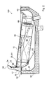
- FIGS. 1 and 2 show an embodiment of a counter insert according to the invention in operating positions.
- the counter insert 100 has a trough 30, a goods support surface 10 and a handle 20 for lifting at least the goods support surface 10 in a tilt position.
- a cooling device 60 is present below the goods support surface 10. This can be firmly connected to the goods support surface 10. In operating positions, the cooling device 60 is thus largely received in the tub 30.
- the cooling device 60 has an intake opening 62, through which air to be cooled, in particular from an area above the goods support surface 10, can be sucked into the cooling device 60.
- the cooling device 60 may have an intake fan 65. The sucked air then flows through an evaporator 66 of the cooling device 60 and is cooled. Through an open side 61 of the cooling device 60, the cooled air finally leaves the cooling device 60.
- the cooling device 60 thus forms part of a flow channel in which all of the air drawn in through the suction opening 62 is discharged on the open side 61.
- a lower boundary of the cooling device 60 is expedient.
- the lower boundary of the cooling device 60 is formed approximately through the bottom of the tub 30. That is, the bottom of the tub 30 is shaped so that air to be cooled is discharged through the open side 61 of the cooler 60.
- counter insert 100 is the goods support 10 in an inclined, that is raised, position.
- the cooling device 60 is thereby also raised and thereby spaced from the bottom of the trough 30.
- a drag plate 63 is present. This is pivotally hinged to the cooling device 60. When lifting the goods support surface 10 and thus the cooling device 60, the drag plate 63 folds down due to its own weight and thus secures a guide of the air to be cooled.
- the handle 20 If the handle 20 is raised by a user, the handle 20 is automatically swung out and thereby brought into the supporting position.
- a spring device 50 is present, which is connected to the goods support surface 10.
- the spring device 50 is attached to a connecting element 12 which is connected to the goods support surface 10.
- the handle 20 is also attached to the connecting element 12 and is pivotable to this. In the in the FIGS. 1 and 2 shown operating positions, the spring device 50 is largely surrounded by the handle 20.
- the spring device 50 presses the handle 20 against an inner rear wall 31 of the trough 30.
- a rear side 26 of the handle 20 is shaped such that in the basic position in which a lower part of the handle 20 is received in the interior of the trough 30 is, this is at least in a partial area parallel to the inner rear wall 31 of the tub 30.
- the rear side 26 of the handle 20 lies flat against the inner rear wall 31.
- the inflow opening 23 in the handle 20 remains free and faces the cooling device.
- the handle 20 serves not only for lifting the goods support surface 10 and for supporting the goods support surface 10 in an inclined position, but also for guiding cooled air to the goods support surface 10.
- the handle 20 is hollow and has an inflow opening 23 and an outflow opening 24 , Both in the basic position and in the support position, the handle 20 is in a position in which the inflow opening 23 is directly adjacent to the open side 61 of the cooling device 60. As a result, the entire air cooled by the cooling device 60 reaches the handle 20 and subsequently out of the outflow opening 24 onto the goods support surface 10.
- a bottom 21 of the handle 20 may be airtight with a part of the cooling device Complete 60.
- the underside 21 of the handle 20 may be rounded.
- the goods support surface 10 on the in Fig. 2 lift out the tilt position shown. This case is in Fig. 3 shown.
- the interior of the tub 30 and the bottom of the cooling device 60 are accessible.
- the open side 61 is accessible to operating personnel, so that the cooling device 60, for example, can be cleaned or maintained from the inside more easily.
- the handle 20 is kept independent in the open position.
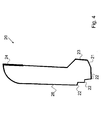
- Fig. 4 shows a handle 20 of another embodiment of a counter insert according to the invention.
- the handle 20 shown here is designed to support the goods support surface 10 in different inclination positions, that is, inclination angles.
- the handle 20 in a lower region, which can be supported on the fixed part 35, a stepped support portion 22.
- a stepped support portion 22 is at least two steps 22, in the illustrated case three steps 22, available.
- a different angle of inclination can be adjusted.
- the counter insert according to the invention it is possible to make an adjustment of the inclination angle of the goods support surface solely by lifting the handle.
- the counter insert according to the invention in the raised, open position allows a good cleaning possibility of the tub and underside of the cooling device.
- the goods support 10 can be folded up by unlocking without entrainment of the cooling device 60, so that a particularly good Access for cleaning purposes is enabled.
- the handle height can be variable - depending on the height of the goods to be cooled - executed.
Landscapes
- Physics & Mathematics (AREA)
- Thermal Sciences (AREA)
- Devices That Are Associated With Refrigeration Equipment (AREA)
Applications Claiming Priority (1)
| Application Number | Priority Date | Filing Date | Title |
|---|---|---|---|
| DE102010055634A DE102010055634B3 (de) | 2010-12-22 | 2010-12-22 | Thekeneinsatz |
Publications (2)
| Publication Number | Publication Date |
|---|---|
| EP2468146A1 true EP2468146A1 (fr) | 2012-06-27 |
| EP2468146B1 EP2468146B1 (fr) | 2013-07-17 |
Family
ID=45421757
Family Applications (1)
| Application Number | Title | Priority Date | Filing Date |
|---|---|---|---|
| EP20110009689 Active EP2468146B1 (fr) | 2010-12-22 | 2011-12-08 | Meuble d'exposition refrigéré |
Country Status (2)
| Country | Link |
|---|---|
| EP (1) | EP2468146B1 (fr) |
| DE (1) | DE102010055634B3 (fr) |
Cited By (1)
| Publication number | Priority date | Publication date | Assignee | Title |
|---|---|---|---|---|
| DE202015106630U1 (de) | 2015-12-04 | 2015-12-22 | Hagola Gastronomie-Technik Gmbh + Co. Kg | Umluftwanne |
Families Citing this family (3)
| Publication number | Priority date | Publication date | Assignee | Title |
|---|---|---|---|---|
| DE202017103161U1 (de) | 2017-05-24 | 2017-06-22 | Hagola Gastronomie-Technik Gmbh + Co. Kg | Umluftwanne |
| DE202017103159U1 (de) | 2017-05-24 | 2017-06-22 | Hagola Gastronomie-Technik Gmbh + Co. Kg | Umluftwanne |
| DE202017103160U1 (de) | 2017-05-24 | 2017-06-22 | Hagola Gastronomie-Technik Gmbh + Co. Kg | Umluftwanne |
Citations (3)
| Publication number | Priority date | Publication date | Assignee | Title |
|---|---|---|---|---|
| DE9409985U1 (de) | 1993-12-10 | 1994-09-29 | Simons, Henri, 42799 Leichlingen | Kühlmöbel, insbesondere für den Ladenbau |
| DE29910539U1 (de) | 1999-06-16 | 1999-12-02 | Hakemann, Edgar, Dipl.-Ing., 27793 Wildeshausen | Umluftkühleinsatz für Warentheken mit in der Neigung veränderbarer Warenauflage |
| DE10064633A1 (de) | 2000-12-22 | 2002-07-04 | Norbert Schmees | Kippbare Thekenplatte und damit gebildete Theke |
-
2010
- 2010-12-22 DE DE102010055634A patent/DE102010055634B3/de not_active Expired - Fee Related
-
2011
- 2011-12-08 EP EP20110009689 patent/EP2468146B1/fr active Active
Patent Citations (3)
| Publication number | Priority date | Publication date | Assignee | Title |
|---|---|---|---|---|
| DE9409985U1 (de) | 1993-12-10 | 1994-09-29 | Simons, Henri, 42799 Leichlingen | Kühlmöbel, insbesondere für den Ladenbau |
| DE29910539U1 (de) | 1999-06-16 | 1999-12-02 | Hakemann, Edgar, Dipl.-Ing., 27793 Wildeshausen | Umluftkühleinsatz für Warentheken mit in der Neigung veränderbarer Warenauflage |
| DE10064633A1 (de) | 2000-12-22 | 2002-07-04 | Norbert Schmees | Kippbare Thekenplatte und damit gebildete Theke |
Cited By (2)
| Publication number | Priority date | Publication date | Assignee | Title |
|---|---|---|---|---|
| DE202015106630U1 (de) | 2015-12-04 | 2015-12-22 | Hagola Gastronomie-Technik Gmbh + Co. Kg | Umluftwanne |
| EP3175741A1 (fr) | 2015-12-04 | 2017-06-07 | HAGOLA Gastronomie-Technik GmbH + Co. KG | Bac de convection |
Also Published As
| Publication number | Publication date |
|---|---|
| EP2468146B1 (fr) | 2013-07-17 |
| DE102010055634B3 (de) | 2012-04-05 |
Similar Documents
| Publication | Publication Date | Title |
|---|---|---|
| DE202010016904U1 (de) | Thekeneinsatz | |
| EP2424421B1 (fr) | Dispositif de réglage en hauteur d'un support guidé sur au moins une glissière d'extraction dans un appareil électroménager | |
| DE102007002241B4 (de) | Vorrichtung zum Abzug von Kochdünsten | |
| EP2540922B1 (fr) | Système de superstructure pour un écoulement se trouvant dans une zone au sol | |
| EP3793407B1 (fr) | Mécanisme de coulissement et de pivotement d'une tablette/clayette d'un meuble ou d'un appareil électroménager, et meuble ou appareil électroménager | |
| DE102014217107A1 (de) | Behältnisaufnahmevorrichtung für einen Fahrzeuginnenraum | |
| EP2468146B1 (fr) | Meuble d'exposition refrigéré | |
| DE19626937C2 (de) | Vorrichtung zur Geräuschminderung an einer Schiebedachöffnung eines Fahrzeugs | |
| WO2007128731A2 (fr) | Support de denrées à réfrigérer pour un appareil de réfrigération | |
| WO2016008678A1 (fr) | Lave-vaisselle domestique | |
| DE102011109957B4 (de) | Waschkabinenvorrichtung zum Waschen von Werkstücken oder dergleichen | |
| DE102007063897B3 (de) | Vorrichtung zum Abzug von Kochdünsten | |
| EP2959800B1 (fr) | Meuble avec un dispositif destiné à l'accouplement amovible d'un chargeur intérieur sur un chargeur extérieur d'un meuble | |
| EP3727089B1 (fr) | Double paroi latérale de tiroir avec un bord inferieur arriere arrondi | |
| DE827295C (de) | Wendefenster und Beschlaege dafuer | |
| EP2505311B1 (fr) | Dispositif de fermeture pour une ouverture d'une chambre de sablage | |
| DE19929357A1 (de) | Vorrichtung zur Halterung von wenigstens einer Gasflasche und Wohnfahrzeug | |
| DE102020104583A1 (de) | Schubladenvorrichtung für einen Reinigungswagen und Reinigungswagen mit einer Schubladenvorrichtung | |
| DE202010000641U1 (de) | Lamellenfenster | |
| DE7811011U1 (de) | Klappenbeschlag | |
| EP1747733B1 (fr) | Meuble, en particulier un table de bureau | |
| EP1293369B1 (fr) | Toit de véhicule avec un panneau basculant | |
| DE625207C (de) | Vorrichtung zur zugfreien Belueftung und Entlueftung von Raeumen | |
| DE202015005933U1 (de) | Nachrüstbare Schublade für Tische | |
| DE102016225807A1 (de) | Haushaltsgeschirrspülmaschine |
Legal Events
| Date | Code | Title | Description |
|---|---|---|---|
| AK | Designated contracting states |
Kind code of ref document: A1 Designated state(s): AL AT BE BG CH CY CZ DE DK EE ES FI FR GB GR HR HU IE IS IT LI LT LU LV MC MK MT NL NO PL PT RO RS SE SI SK SM TR |
|
| AX | Request for extension of the european patent |
Extension state: BA ME |
|
| PUAI | Public reference made under article 153(3) epc to a published international application that has entered the european phase |
Free format text: ORIGINAL CODE: 0009012 |
|
| 17P | Request for examination filed |
Effective date: 20121001 |
|
| GRAP | Despatch of communication of intention to grant a patent |
Free format text: ORIGINAL CODE: EPIDOSNIGR1 |
|
| GRAS | Grant fee paid |
Free format text: ORIGINAL CODE: EPIDOSNIGR3 |
|
| GRAA | (expected) grant |
Free format text: ORIGINAL CODE: 0009210 |
|
| AK | Designated contracting states |
Kind code of ref document: B1 Designated state(s): AL AT BE BG CH CY CZ DE DK EE ES FI FR GB GR HR HU IE IS IT LI LT LU LV MC MK MT NL NO PL PT RO RS SE SI SK SM TR |
|
| REG | Reference to a national code |
Ref country code: GB Ref legal event code: FG4D Free format text: NOT ENGLISH |
|
| REG | Reference to a national code |
Ref country code: CH Ref legal event code: EP |
|
| REG | Reference to a national code |
Ref country code: IE Ref legal event code: FG4D Free format text: LANGUAGE OF EP DOCUMENT: GERMAN |
|
| REG | Reference to a national code |
Ref country code: AT Ref legal event code: REF Ref document number: 621644 Country of ref document: AT Kind code of ref document: T Effective date: 20130815 |
|
| REG | Reference to a national code |
Ref country code: DE Ref legal event code: R096 Ref document number: 502011001039 Country of ref document: DE Effective date: 20130912 |
|
| REG | Reference to a national code |
Ref country code: CH Ref legal event code: NV Representative=s name: BOGENSBERGER PATENT- AND MARKENBUERO DR. BURKH, LI |
|
| REG | Reference to a national code |
Ref country code: NL Ref legal event code: T3 |
|
| REG | Reference to a national code |
Ref country code: LT Ref legal event code: MG4D |
|
| PG25 | Lapsed in a contracting state [announced via postgrant information from national office to epo] |
Ref country code: NO Free format text: LAPSE BECAUSE OF FAILURE TO SUBMIT A TRANSLATION OF THE DESCRIPTION OR TO PAY THE FEE WITHIN THE PRESCRIBED TIME-LIMIT Effective date: 20131017 Ref country code: SE Free format text: LAPSE BECAUSE OF FAILURE TO SUBMIT A TRANSLATION OF THE DESCRIPTION OR TO PAY THE FEE WITHIN THE PRESCRIBED TIME-LIMIT Effective date: 20130717 Ref country code: HR Free format text: LAPSE BECAUSE OF FAILURE TO SUBMIT A TRANSLATION OF THE DESCRIPTION OR TO PAY THE FEE WITHIN THE PRESCRIBED TIME-LIMIT Effective date: 20130717 Ref country code: CY Free format text: LAPSE BECAUSE OF FAILURE TO SUBMIT A TRANSLATION OF THE DESCRIPTION OR TO PAY THE FEE WITHIN THE PRESCRIBED TIME-LIMIT Effective date: 20130828 Ref country code: PT Free format text: LAPSE BECAUSE OF FAILURE TO SUBMIT A TRANSLATION OF THE DESCRIPTION OR TO PAY THE FEE WITHIN THE PRESCRIBED TIME-LIMIT Effective date: 20131118 Ref country code: LT Free format text: LAPSE BECAUSE OF FAILURE TO SUBMIT A TRANSLATION OF THE DESCRIPTION OR TO PAY THE FEE WITHIN THE PRESCRIBED TIME-LIMIT Effective date: 20130717 Ref country code: IS Free format text: LAPSE BECAUSE OF FAILURE TO SUBMIT A TRANSLATION OF THE DESCRIPTION OR TO PAY THE FEE WITHIN THE PRESCRIBED TIME-LIMIT Effective date: 20131117 |
|
| PG25 | Lapsed in a contracting state [announced via postgrant information from national office to epo] |
Ref country code: ES Free format text: LAPSE BECAUSE OF FAILURE TO SUBMIT A TRANSLATION OF THE DESCRIPTION OR TO PAY THE FEE WITHIN THE PRESCRIBED TIME-LIMIT Effective date: 20131028 Ref country code: PL Free format text: LAPSE BECAUSE OF FAILURE TO SUBMIT A TRANSLATION OF THE DESCRIPTION OR TO PAY THE FEE WITHIN THE PRESCRIBED TIME-LIMIT Effective date: 20130717 Ref country code: FI Free format text: LAPSE BECAUSE OF FAILURE TO SUBMIT A TRANSLATION OF THE DESCRIPTION OR TO PAY THE FEE WITHIN THE PRESCRIBED TIME-LIMIT Effective date: 20130717 Ref country code: GR Free format text: LAPSE BECAUSE OF FAILURE TO SUBMIT A TRANSLATION OF THE DESCRIPTION OR TO PAY THE FEE WITHIN THE PRESCRIBED TIME-LIMIT Effective date: 20131018 Ref country code: SI Free format text: LAPSE BECAUSE OF FAILURE TO SUBMIT A TRANSLATION OF THE DESCRIPTION OR TO PAY THE FEE WITHIN THE PRESCRIBED TIME-LIMIT Effective date: 20130717 Ref country code: LV Free format text: LAPSE BECAUSE OF FAILURE TO SUBMIT A TRANSLATION OF THE DESCRIPTION OR TO PAY THE FEE WITHIN THE PRESCRIBED TIME-LIMIT Effective date: 20130717 |
|
| PG25 | Lapsed in a contracting state [announced via postgrant information from national office to epo] |
Ref country code: CY Free format text: LAPSE BECAUSE OF FAILURE TO SUBMIT A TRANSLATION OF THE DESCRIPTION OR TO PAY THE FEE WITHIN THE PRESCRIBED TIME-LIMIT Effective date: 20130717 |
|
| PG25 | Lapsed in a contracting state [announced via postgrant information from national office to epo] |
Ref country code: CZ Free format text: LAPSE BECAUSE OF FAILURE TO SUBMIT A TRANSLATION OF THE DESCRIPTION OR TO PAY THE FEE WITHIN THE PRESCRIBED TIME-LIMIT Effective date: 20130717 Ref country code: DK Free format text: LAPSE BECAUSE OF FAILURE TO SUBMIT A TRANSLATION OF THE DESCRIPTION OR TO PAY THE FEE WITHIN THE PRESCRIBED TIME-LIMIT Effective date: 20130717 Ref country code: SK Free format text: LAPSE BECAUSE OF FAILURE TO SUBMIT A TRANSLATION OF THE DESCRIPTION OR TO PAY THE FEE WITHIN THE PRESCRIBED TIME-LIMIT Effective date: 20130717 Ref country code: EE Free format text: LAPSE BECAUSE OF FAILURE TO SUBMIT A TRANSLATION OF THE DESCRIPTION OR TO PAY THE FEE WITHIN THE PRESCRIBED TIME-LIMIT Effective date: 20130717 Ref country code: RO Free format text: LAPSE BECAUSE OF FAILURE TO SUBMIT A TRANSLATION OF THE DESCRIPTION OR TO PAY THE FEE WITHIN THE PRESCRIBED TIME-LIMIT Effective date: 20130717 |
|
| PLBE | No opposition filed within time limit |
Free format text: ORIGINAL CODE: 0009261 |
|
| STAA | Information on the status of an ep patent application or granted ep patent |
Free format text: STATUS: NO OPPOSITION FILED WITHIN TIME LIMIT |
|
| PG25 | Lapsed in a contracting state [announced via postgrant information from national office to epo] |
Ref country code: IT Free format text: LAPSE BECAUSE OF FAILURE TO SUBMIT A TRANSLATION OF THE DESCRIPTION OR TO PAY THE FEE WITHIN THE PRESCRIBED TIME-LIMIT Effective date: 20130717 |
|
| 26N | No opposition filed |
Effective date: 20140422 |
|
| BERE | Be: lapsed |
Owner name: HAGOLA GASTRONOMIE-TECHNIK G.M.B.H. & CO. KG Effective date: 20131231 |
|
| REG | Reference to a national code |
Ref country code: DE Ref legal event code: R097 Ref document number: 502011001039 Country of ref document: DE Effective date: 20140422 |
|
| PG25 | Lapsed in a contracting state [announced via postgrant information from national office to epo] |
Ref country code: LU Free format text: LAPSE BECAUSE OF FAILURE TO SUBMIT A TRANSLATION OF THE DESCRIPTION OR TO PAY THE FEE WITHIN THE PRESCRIBED TIME-LIMIT Effective date: 20131208 |
|
| REG | Reference to a national code |
Ref country code: IE Ref legal event code: MM4A |
|
| REG | Reference to a national code |
Ref country code: FR Ref legal event code: ST Effective date: 20140829 |
|
| PG25 | Lapsed in a contracting state [announced via postgrant information from national office to epo] |
Ref country code: BE Free format text: LAPSE BECAUSE OF NON-PAYMENT OF DUE FEES Effective date: 20131231 Ref country code: IE Free format text: LAPSE BECAUSE OF NON-PAYMENT OF DUE FEES Effective date: 20131208 |
|
| PG25 | Lapsed in a contracting state [announced via postgrant information from national office to epo] |
Ref country code: FR Free format text: LAPSE BECAUSE OF NON-PAYMENT OF DUE FEES Effective date: 20131231 |
|
| PG25 | Lapsed in a contracting state [announced via postgrant information from national office to epo] |
Ref country code: MC Free format text: LAPSE BECAUSE OF FAILURE TO SUBMIT A TRANSLATION OF THE DESCRIPTION OR TO PAY THE FEE WITHIN THE PRESCRIBED TIME-LIMIT Effective date: 20130717 |
|
| PG25 | Lapsed in a contracting state [announced via postgrant information from national office to epo] |
Ref country code: SM Free format text: LAPSE BECAUSE OF FAILURE TO SUBMIT A TRANSLATION OF THE DESCRIPTION OR TO PAY THE FEE WITHIN THE PRESCRIBED TIME-LIMIT Effective date: 20130717 |
|
| PG25 | Lapsed in a contracting state [announced via postgrant information from national office to epo] |
Ref country code: TR Free format text: LAPSE BECAUSE OF FAILURE TO SUBMIT A TRANSLATION OF THE DESCRIPTION OR TO PAY THE FEE WITHIN THE PRESCRIBED TIME-LIMIT Effective date: 20130717 |
|
| PG25 | Lapsed in a contracting state [announced via postgrant information from national office to epo] |
Ref country code: RS Free format text: LAPSE BECAUSE OF FAILURE TO SUBMIT A TRANSLATION OF THE DESCRIPTION OR TO PAY THE FEE WITHIN THE PRESCRIBED TIME-LIMIT Effective date: 20131017 Ref country code: HU Free format text: LAPSE BECAUSE OF FAILURE TO SUBMIT A TRANSLATION OF THE DESCRIPTION OR TO PAY THE FEE WITHIN THE PRESCRIBED TIME-LIMIT; INVALID AB INITIO Effective date: 20111208 Ref country code: BG Free format text: LAPSE BECAUSE OF FAILURE TO SUBMIT A TRANSLATION OF THE DESCRIPTION OR TO PAY THE FEE WITHIN THE PRESCRIBED TIME-LIMIT Effective date: 20130717 Ref country code: MK Free format text: LAPSE BECAUSE OF FAILURE TO SUBMIT A TRANSLATION OF THE DESCRIPTION OR TO PAY THE FEE WITHIN THE PRESCRIBED TIME-LIMIT Effective date: 20130717 |
|
| PG25 | Lapsed in a contracting state [announced via postgrant information from national office to epo] |
Ref country code: MT Free format text: LAPSE BECAUSE OF FAILURE TO SUBMIT A TRANSLATION OF THE DESCRIPTION OR TO PAY THE FEE WITHIN THE PRESCRIBED TIME-LIMIT Effective date: 20130717 |
|
| GBPC | Gb: european patent ceased through non-payment of renewal fee |
Effective date: 20151208 |
|
| PG25 | Lapsed in a contracting state [announced via postgrant information from national office to epo] |
Ref country code: GB Free format text: LAPSE BECAUSE OF NON-PAYMENT OF DUE FEES Effective date: 20151208 |
|
| REG | Reference to a national code |
Ref country code: DE Ref legal event code: R082 Ref document number: 502011001039 Country of ref document: DE Representative=s name: WUNDERLICH & HEIM PATENTANWAELTE PARTNERSCHAFT, DE |
|
| PG25 | Lapsed in a contracting state [announced via postgrant information from national office to epo] |
Ref country code: AL Free format text: LAPSE BECAUSE OF FAILURE TO SUBMIT A TRANSLATION OF THE DESCRIPTION OR TO PAY THE FEE WITHIN THE PRESCRIBED TIME-LIMIT Effective date: 20130717 |
|
| P01 | Opt-out of the competence of the unified patent court (upc) registered |
Effective date: 20230505 |
|
| PGFP | Annual fee paid to national office [announced via postgrant information from national office to epo] |
Ref country code: NL Payment date: 20231219 Year of fee payment: 13 |
|
| PGFP | Annual fee paid to national office [announced via postgrant information from national office to epo] |
Ref country code: CH Payment date: 20240110 Year of fee payment: 13 |
|
| REG | Reference to a national code |
Ref country code: CH Ref legal event code: PL |
|
| REG | Reference to a national code |
Ref country code: NL Ref legal event code: MM Effective date: 20250101 |
|
| PG25 | Lapsed in a contracting state [announced via postgrant information from national office to epo] |
Ref country code: NL Free format text: LAPSE BECAUSE OF NON-PAYMENT OF DUE FEES Effective date: 20250101 |
|
| PG25 | Lapsed in a contracting state [announced via postgrant information from national office to epo] |
Ref country code: CH Free format text: LAPSE BECAUSE OF NON-PAYMENT OF DUE FEES Effective date: 20241231 |
|
| PGFP | Annual fee paid to national office [announced via postgrant information from national office to epo] |
Ref country code: AT Payment date: 20251215 Year of fee payment: 15 |
|
| PGFP | Annual fee paid to national office [announced via postgrant information from national office to epo] |
Ref country code: DE Payment date: 20251217 Year of fee payment: 15 |