EP2468355B1 - Vorrichtung zur Implantation eines elektrischen Simulationssystems und einer blattartigen elektrischen Simulationsleitung - Google Patents
Vorrichtung zur Implantation eines elektrischen Simulationssystems und einer blattartigen elektrischen Simulationsleitung Download PDFInfo
- Publication number
- EP2468355B1 EP2468355B1 EP12157400.8A EP12157400A EP2468355B1 EP 2468355 B1 EP2468355 B1 EP 2468355B1 EP 12157400 A EP12157400 A EP 12157400A EP 2468355 B1 EP2468355 B1 EP 2468355B1
- Authority
- EP
- European Patent Office
- Prior art keywords
- introducer
- outer sheath
- electrical stimulation
- inner penetrator
- lead
- Prior art date
- Legal status (The legal status is an assumption and is not a legal conclusion. Google has not performed a legal analysis and makes no representation as to the accuracy of the status listed.)
- Expired - Lifetime
Links
- 230000000638 stimulation Effects 0.000 title claims abstract description 67
- 238000003780 insertion Methods 0.000 claims abstract description 20
- 230000037431 insertion Effects 0.000 claims abstract description 20
- 210000000944 nerve tissue Anatomy 0.000 claims abstract 11
- 210000001519 tissue Anatomy 0.000 claims description 24
- 210000000578 peripheral nerve Anatomy 0.000 claims description 15
- 210000004749 ligamentum flavum Anatomy 0.000 claims description 12
- 238000002594 fluoroscopy Methods 0.000 claims description 6
- 239000000463 material Substances 0.000 claims description 4
- 210000001032 spinal nerve Anatomy 0.000 claims description 3
- RTAQQCXQSZGOHL-UHFFFAOYSA-N Titanium Chemical compound [Ti] RTAQQCXQSZGOHL-UHFFFAOYSA-N 0.000 claims description 2
- 229910052751 metal Inorganic materials 0.000 claims description 2
- 239000002184 metal Substances 0.000 claims description 2
- 229920000260 silastic Polymers 0.000 claims description 2
- 229910001220 stainless steel Inorganic materials 0.000 claims description 2
- 239000010935 stainless steel Substances 0.000 claims description 2
- 239000010936 titanium Substances 0.000 claims description 2
- 229910001200 Ferrotitanium Inorganic materials 0.000 claims 1
- 238000012800 visualization Methods 0.000 claims 1
- 238000000034 method Methods 0.000 description 19
- 239000007943 implant Substances 0.000 description 10
- 210000000278 spinal cord Anatomy 0.000 description 6
- 241001269524 Dura Species 0.000 description 4
- 208000002193 Pain Diseases 0.000 description 3
- 230000004007 neuromodulation Effects 0.000 description 3
- 230000008569 process Effects 0.000 description 3
- 230000004075 alteration Effects 0.000 description 2
- 210000003484 anatomy Anatomy 0.000 description 2
- 239000000835 fiber Substances 0.000 description 2
- 238000012986 modification Methods 0.000 description 2
- 230000004048 modification Effects 0.000 description 2
- 210000003205 muscle Anatomy 0.000 description 2
- 210000005036 nerve Anatomy 0.000 description 2
- 230000007383 nerve stimulation Effects 0.000 description 2
- 206010033675 panniculitis Diseases 0.000 description 2
- 208000035824 paresthesia Diseases 0.000 description 2
- 230000004044 response Effects 0.000 description 2
- 210000004304 subcutaneous tissue Anatomy 0.000 description 2
- 238000006467 substitution reaction Methods 0.000 description 2
- 230000001225 therapeutic effect Effects 0.000 description 2
- 208000000094 Chronic Pain Diseases 0.000 description 1
- 238000005452 bending Methods 0.000 description 1
- 210000004556 brain Anatomy 0.000 description 1
- 210000001217 buttock Anatomy 0.000 description 1
- 210000003169 central nervous system Anatomy 0.000 description 1
- 230000000694 effects Effects 0.000 description 1
- 238000002513 implantation Methods 0.000 description 1
- 230000006872 improvement Effects 0.000 description 1
- 238000002684 laminectomy Methods 0.000 description 1
- 210000003041 ligament Anatomy 0.000 description 1
- 238000007726 management method Methods 0.000 description 1
- 231100000862 numbness Toxicity 0.000 description 1
- 229920000642 polymer Polymers 0.000 description 1
- 238000002271 resection Methods 0.000 description 1
- 230000035807 sensation Effects 0.000 description 1
- 230000007480 spreading Effects 0.000 description 1
- 238000010561 standard procedure Methods 0.000 description 1
- 238000007920 subcutaneous administration Methods 0.000 description 1
- 229910052719 titanium Inorganic materials 0.000 description 1
Images



Classifications
-
- A—HUMAN NECESSITIES
- A61—MEDICAL OR VETERINARY SCIENCE; HYGIENE
- A61B—DIAGNOSIS; SURGERY; IDENTIFICATION
- A61B17/00—Surgical instruments, devices or methods
- A61B17/34—Trocars; Puncturing needles
- A61B17/3415—Trocars; Puncturing needles for introducing tubes or catheters, e.g. gastrostomy tubes, drain catheters
-
- A—HUMAN NECESSITIES
- A61—MEDICAL OR VETERINARY SCIENCE; HYGIENE
- A61B—DIAGNOSIS; SURGERY; IDENTIFICATION
- A61B17/00—Surgical instruments, devices or methods
- A61B17/34—Trocars; Puncturing needles
- A61B17/3468—Trocars; Puncturing needles for implanting or removing devices, e.g. prostheses, implants, seeds, wires
-
- A—HUMAN NECESSITIES
- A61—MEDICAL OR VETERINARY SCIENCE; HYGIENE
- A61N—ELECTROTHERAPY; MAGNETOTHERAPY; RADIATION THERAPY; ULTRASOUND THERAPY
- A61N1/00—Electrotherapy; Circuits therefor
- A61N1/02—Details
- A61N1/04—Electrodes
- A61N1/05—Electrodes for implantation or insertion into the body, e.g. heart electrode
- A61N1/0551—Spinal or peripheral nerve electrodes
- A61N1/0553—Paddle shaped electrodes, e.g. for laminotomy
-
- A—HUMAN NECESSITIES
- A61—MEDICAL OR VETERINARY SCIENCE; HYGIENE
- A61B—DIAGNOSIS; SURGERY; IDENTIFICATION
- A61B17/00—Surgical instruments, devices or methods
- A61B17/34—Trocars; Puncturing needles
- A61B17/3401—Puncturing needles for the peridural or subarachnoid space or the plexus, e.g. for anaesthesia
-
- A—HUMAN NECESSITIES
- A61—MEDICAL OR VETERINARY SCIENCE; HYGIENE
- A61N—ELECTROTHERAPY; MAGNETOTHERAPY; RADIATION THERAPY; ULTRASOUND THERAPY
- A61N1/00—Electrotherapy; Circuits therefor
- A61N1/18—Applying electric currents by contact electrodes
- A61N1/32—Applying electric currents by contact electrodes alternating or intermittent currents
- A61N1/36—Applying electric currents by contact electrodes alternating or intermittent currents for stimulation
- A61N1/36014—External stimulators, e.g. with patch electrodes
- A61N1/36017—External stimulators, e.g. with patch electrodes with leads or electrodes penetrating the skin
-
- A—HUMAN NECESSITIES
- A61—MEDICAL OR VETERINARY SCIENCE; HYGIENE
- A61N—ELECTROTHERAPY; MAGNETOTHERAPY; RADIATION THERAPY; ULTRASOUND THERAPY
- A61N1/00—Electrotherapy; Circuits therefor
- A61N1/18—Applying electric currents by contact electrodes
- A61N1/32—Applying electric currents by contact electrodes alternating or intermittent currents
- A61N1/36—Applying electric currents by contact electrodes alternating or intermittent currents for stimulation
- A61N1/3605—Implantable neurostimulators for stimulating central or peripheral nerve system
Definitions
- This invention relates generally to electrical stimulation leads for medical applications and in particular to an apparatus for implanting an electrical stimulation system that includes a paddle style electrical stimulation lead.
- Electrodes are used to treat regions of the body that are affected by chronic pain from a variety of etiologies.
- One method of delivering electrical energy is to implant an electrode and position it in a precise location adjacent the spinal cord such that stimulation of the electrode causes a subjective sensation of numbness or tingling in the affected region of the body, known as "paresthesia.” Pain managing electrical energy is commonly delivered through electrodes positioned external to the dura layer surrounding the spinal cord.
- the electrodes may be carried by either of two primary vehicles: a percutaneous lead and a laminotomy or "paddle" lead.
- Percutaneous leads commonly have three or more equally-spaced electrodes. They are positioned above the dura layer using a needle that is passed through the skin, between the desired vertebrae and onto the top of the dura. Percutaneous leads deliver energy radially in all directions because of the circumferential nature of the electrode. Percutaneous leads can be implanted using a minimally invasive technique. In a typical percutaneous lead placement, a trial stimulation procedure is performed to determine the optimal location for the lead. Here, a needle is placed through the skin and between the desired vertebrae. The percutaneous lead is then threaded through the needle into the desired location over the spinal cord dura. Percutaneous leads may also be positioned in other regions of the body near peripheral nerves for the same purpose.
- Laminotomy or paddle style leads have a paddle-like configuration and typically possess multiple electrodes arranged in one or more independent columns.
- Paddle style leads provide a more focused energy delivery than percutaneous leads because electrodes may be present on only one surface of the lead. Paddle style leads may be desirable in certain situations because they provide more direct stimulation to a specific surface and require less energy to produce a desired effect. Because paddle style leads are larger than percutaneous leads, they have historically required surgical implantation through a procedure known as partial laminectomy that requires the resection and removal of vertebral tissue.
- the invention is defined in claim 1.
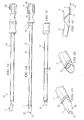
- FIGURE 1A illustrates an example introducer 10 for implanting a paddle style electrical stimulation lead percutaneously.
- Introducer 10 may be used to percutaneously introduce a percutaneous or paddle style lead into the epidural space of a user who requires electrical stimulation treatment directed to spinal nerve tissue, for example, for pain management.
- paddle style leads generally have a width about two times the height of the face of the paddle.
- introducer 10 may be used to implant a percutaneous or paddle style lead into other tissue for electrostimulation treatment of a peripheral nerve.
- introducer 10 includes an outer sheath 12 and an inner penetrator 14.
- FIGURE 1B illustrates an example inner penetrator 14 disassembled from outer sheath 12.
- Inner penetrator 14 includes handle 16, connector 17, and body 18 having proximal end 19 and distal end or tip 20. Tip 20 may be tapered.
- Connector 17 connects handle 16 to body 18.
- An inner channel 22 is formed through handle 16 and body 18 and connects opening 26 of handle 16 to opening 21 of tip 20.
- Inner channel 22 may be configured to attach to a syringe.
- Inner channel 22 is wide enough to accommodate guide wires of various sizes along which introducer 10 may be advanced during use.
- Channel 22 may taper or otherwise decrease in diameter as it traverses connector 17 at the handle-body junction.
- Inner penetrator 14 may be formed from a plastic, such as silastic or another polymer, or any other suitable material.
- Tip 20 of inner penetrator 14 is configured to be curved as defined in claim 1.
- FIGURE 1C illustrates outer sheath 12 disassembled from inner penetrator 14.
- the lumen of outer sheath 12 may range in width, for example from approximately 2mm to approximately 6mm.
- the lumen may be oblong, oval, or substantially rectangular as needed to accommodate paddle style leads of various configurations.
- Outer sheath 12 may taper slightly at tip 29. Tip 29 of outer sheath 12 may be beveled to allow easier passage through tissue and to allow inner penetrator 14 to protrude out of tip 29.
- Outer sheath 12 is preferably formed from a metal, such as stainless steel or titanium, or any other suitable material that is stiff and resists bending when outer sheath 12 is inserted through the paravertebral tissue and into the epidural space.
- inner penetrator 14 includes tapered tip 20 shown in FIGURE 1D . Tapered tip 20 protrudes out of outer sheath 12. Tapered tip 20 preferably allows introducer 10 to pass easily over a guide wire without creating a false passage in an undesirable location in the tissue.
- tip 20 includes a raised circumferential shoulder or ridge 23 configured to provide an indication or "feel” to a physician as raised ridge 23 comes in contact with the ligamentum flavum.
- This "feel” occurs when raised ridge 23 comes in contact with the ligamentum flavum causing a slight resistance, pressure, or “notch” feel to the physician as raised ridge 23 comes in contact with and passes through the ligamentum flavum.
- this aspect may provide an important indication to the physician as to the location of outer sheath 12 and thus introducer 10 as a whole.
- Such a raised ridge 23 can also be applied to needles or cutting devices that otherwise fail to provide physicians sufficient "feel” or a locative indication as the needle cuts through the ligamentum flavum.
- the edge of outer sheath 12 in FIGURE 1E could be configured into a cutting surface for a paddle insertion type needle.
- the improvement of raised ridge 23 on such a cutting device would provide the needed "feel" or indication to the physician as to where the needle was in the human tissue, thus providing confidence to the physician, as the physician uses such a large needle, that the needle has not yet entered the interthecal space.
- raised ridge 23 assists in spreading the fibers of the paravertebral muscle and ligaments as it is inserted.
- Raised ridge 23 may be angled to assist insertion, for example, at an angle of thirty-five to forty-five degrees or any other angle that would facilitate passage of outer sheath through tissue.
- raised ridge 23 ultimately makes contact with the ligamentum flavum and rests against it during insertion of a guide wire and an electrical stimulation lead.
- outer sheath 12, inner penetrator 14, or both may be formed from radio-opaque material or may include radio-opaque markers that allow the position of outer sheath 12, inner penetrator 14, or both to be visualized with fluoroscopy or plain x-rays, for example, during the insertion process to insure proper positioning in the epidural space.
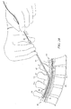
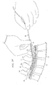
- FIGURES 2A-F illustrate an example method of implanting a paddle style electrical stimulation lead into a human's epidural space using an example introducer 10.
- Spinal cord 47 is also shown.
- a location between two vertebrae is selected for the procedure.
- the site may be selected using fluoroscopy.
- the first step in performing the procedure is to insert needle 41, preferably at an angle, into the skin, and through the subcutaneous tissue and ligamentum flavum 44 of the spine, and into a human's epidural space 40.
- the introducer might be inserted at an angle of approximately thirty-five to approximately forty-five degrees.
- FIGURE 2A illustrates insertion of needle 41 through the skin between spinous processes 42 of two vertebrae 43. Entry into epidural space 40 by needle 41 may be conformed using standard methods such as the "loss-of-resistance" technique after stylet 45, or inner portion of needle 41, is removed.
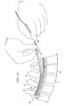
- guide wire 46 may be inserted through needle 41 into epidural space 40, shown in FIGURE 2B .
- a guide wire is used in a preferred embodiment of the method of insertion but is not required to insert a paddle style lead through the introducer. This part of the procedure may be performed under fluoroscopic guidance for example. Fluoroscopy may be used to check the position of guide wire 46 in epidural space 40 before inserting introducer 10. Once the tip of guide wire 46 is within epidural space 40, needle 41 is removed.
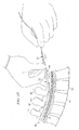
- introducer 10 may then be inserted, preferably at an angle of approximately thirty-five to approximately forty-five degrees, although the exact angle may differ depending on technique and a patient's anatomy, over guide wire 46 and into epidural space 40 using guide wire 46 as a guide.
- the technique of passing introducer 10 over guide wire 46 helps ensure proper placement of introducer 10 into epidural space 40 and helps avoid inadvertent passage of introducer 10 into an unsuitable location.
- the operator may choose to cut the skin around the insertion site with a scalpel to facilitate subsequent entry of introducer 10 through the needle entry site.
- introducer 10 As introducer 10 is passed through the skin it elongates the hole in the skin made by needle 41. As introducer 10 is passed deeper into the paravertebral tissues, it spreads the fibers of tissue, muscle and ligamentum flavum 44 and forms a tract through these tissues and into epidural space 40, preferably without cutting the tissues. At the level in the tissues where introducer 10 meets and penetrates ligamentum flavum 44 there is a second loss of resistance when inner penetrator 14 has completely penetrated the ligamentum flavum 44. Shoulder or ridge 23 of outer sheath 12 is preferably lodged against ligamentum flavum 44 during insertion of a paddle style lead.
- inner penetrator 14 and guide wire 46 may be removed, leaving outer sheath 12 positioned in epidural space 40, as shown in FIGURE 2D .
- paddle style lead 50 may then be inserted through outer sheath 12 and positioned at an optimal vertebral level, using fluoroscopy for example, for the desired therapeutic effect.
- outer sheath 12 may then be removed leaving only paddle style lead 50 in epidural space 40, where paddle style lead 50 can be further manipulated if necessary to achieve a desired therapeutic effect.
- Paddle style lead 50 may be secured by suturing it to a spinous process.
- introducer 10 may be used to implant paddle style lead 50 into epidural space 40 for spinal nerve stimulation.
- the same or an analogous, perhaps smaller, introducer 10 may be used to implant an analogous paddle style lead 50 into any appropriate region of the body for peripheral nerve stimulation.
- a paddle style lead 50 may have an outer sheath 12 and lumen 28 with a width of approximately 1mm to approximately 3mm.
- a similar method of insertion may be used to implant a paddle style electrical stimulation lead into a human's peripheral nerve tissue.
- a site for insertion in tissue near a nerve is selected.
- the first step in performing the procedure is to insert a needle into the skin and through the subcutaneous tissue and into tissue near a peripheral nerve. If the needle has a stylet, it may be removed and a guide wire may be inserted through the needle and into the tissue near a peripheral nerve. A guide wire may not be required. Fluoroscopy may or may not be used to guide insertion of a guide wire into tissue near a peripheral nerve.
- introducer 10 may be inserted, preferably at an angle that would depend on the anatomy of the body near the peripheral nerve to be stimulated. As introducer 10 is passed through tissues, it elongates the tract made by a needle or guide wire and spreads the tissue. After positioning introducer 10 in tissue adjacent to the peripheral nerve to be stimulated, inner penetrator 14 is removed. A paddle style lead may then be inserted through outer sheath 12. Outer sheath 12 may then be removed leaving only the paddle style lead in position near the peripheral nerve to be stimulated.
- FIGURES 3A and 3B there are shown two embodiments of a stimulation system 200, 300.
- the stimulation systems generate and apply a stimulus to a tissue or to a certain location of a body.
- the system 200, 300 includes a stimulation or energy source 210, 310 and a lead 50 for application of the stimulus.
- the lead 110 shown in FIGURES 3A and 3B is the paddle style lead 50.
- the stimulation system 200 includes the lead 50 that is coupled to the stimulation source 210.
- the stimulation source 210 includes an implantable pulse generator (IPG).
- IPG implantable pulse generator
- an implantable pulse generator (IPG) is implanted within the body (not shown) that is to receive electrical stimulation from the stimulation source 210.
- An example IPG may be one manufactured by Advanced Neuromodulation Systems, Inc., such as the Genesis® System, part numbers 3604, 3608, 3609, and 3644.
- the stimulation system 300 includes the lead 50 that is coupled to the stimulation source 310.
- the stimulation source 310 includes a wireless receiver.
- the stimulation source 310 comprising a wireless receiver is implanted within the body (not shown) that is to receive electrical stimulation from the stimulation source 310.
- An example wireless receiver 310 may be those wireless receivers manufactured by Advanced Neuromodulation Systems, Inc., such as the Renew® System, part numbers 3408 and 3416.
- the wireless receiver (not shown) within stimulation source 310 is capable of receiving wireless signals from a wireless transmitter 320.
- the wireless signals are represented in FIGURE 3B by wireless link symbol 330.
- the wireless transmitter 320 and a controller 340 are located outside of the body that is to receive electrical stimulation from the stimulation source 310.
- a user of the stimulation source 310 may use the controller 340 to provide control signals for the operation of the stimulation source 310.
- the controller 340 provides control signals to the wireless transmitter 320.
- the wireless transmitter 320 transmits the control signals (and power) to the receiver in the stimulation source 310 and the stimulation source 310 uses the control signals to vary the signal parameters of the electrical signals that are transmitted through lead 110 to the stimulation site.
- An example wireless transmitter 320 may be those transmitters manufactured by Advanced Neuromodulation Systems, Inc., such as the Renew® System, part numbers 3508 and 3516.
- the connectors are not visible in FIGURES 3A and 3B because the contact electrodes are situated within a receptacle (not shown) of the stimulation source 210, 310.
- the connectors are in electrical contact with a generator (not shown) of electrical signals within the stimulation source 210, 310.
- the stimulation source 210, 310 generates and sends electrical signals via the lead 50 to the electrodes 160.
- the electrodes 160 are located at a stimulation site (not shown) within the body that is to receive electrical stimulation from the electrical signals.
- a stimulation site may be, for example, adjacent to one or more nerves in the central nervous system (e.g., spinal cord) or peripheral nerves.
- the stimulation source 210, 310 is capable of controlling the electrical signals by varying signal parameters (e.g., intensity, duration, frequency) in response to control signals that are provided to the stimulation source 210, 310.
- Lead 110 extends from the insertion site to the implant site (the area of placement of the generator).
- the implant site is typically a subcutaneous pocket that receives and houses the IPG or receiver (providing stimulation source 210, 310).
- the implant site is usually positioned a distance away from the stimulation site, such as near the buttocks or other place in the torso area. In most cases, the implant site (and insertion site) is located in the lower back area, and lead 110 may extend through the epidural space (or other space) in the spine to the stimulation site (e.g., middle or upper back, neck, or brain areas).
- the system of leads and/or extensions may be subject to mechanical forces and movement in response to body movement.
- FIGURE 4 illustrates the steps that may be used to implant a stimulation system 200, 300 into a human.
Landscapes
- Health & Medical Sciences (AREA)
- Life Sciences & Earth Sciences (AREA)
- Surgery (AREA)
- Heart & Thoracic Surgery (AREA)
- General Health & Medical Sciences (AREA)
- Veterinary Medicine (AREA)
- Engineering & Computer Science (AREA)
- Biomedical Technology (AREA)
- Nuclear Medicine, Radiotherapy & Molecular Imaging (AREA)
- Public Health (AREA)
- Animal Behavior & Ethology (AREA)
- Pathology (AREA)
- Medical Informatics (AREA)
- Molecular Biology (AREA)
- Neurosurgery (AREA)
- Cardiology (AREA)
- Radiology & Medical Imaging (AREA)
- Orthopedic Medicine & Surgery (AREA)
- Neurology (AREA)
- Gastroenterology & Hepatology (AREA)
- Electrotherapy Devices (AREA)
Claims (15)
- Ein Inserter (10) zur Implantation einer Elektrostimulationselektrode (50), um die Elektrostimulation von Nervengewebe zu ermöglichen, welcher Folgendes umfasst:ein äußere Hülse (12) um das Einführen der Elektrostimulationselektrode durch die äußere Hülse zu bewerkstelligen, wobei die äußere Hülse (12) zur Einführung in einen menschlichen Körper nahe am Nervengewebe eingesetzt werden kann; undeinen inneren Eindringkörper (14), welcher sich entnehmbar innerhalb der äußeren Hülse (12) befindet, und einen inneren Kanal (22) umfasst, welcher dafür eingerichtet ist, einen Führungsdraht (46) aufzunehmen, und wobei der innere Eindringkörper (14) dafür eingerichtet ist, entlang des Führungsdrahts (46) zu einer gewünschten Stelle bezüglich des Nervengewebes vorangeschoben und von der äußeren Hülse (12) entnommen zu werden, wobei die äußere Hülse (12) im Wesentlichen in der Position zur Einführung der Elektrostimulationselektrode (50) durch die äußere Hülse (12) in die Position nahe des Nervengewebes verbleibt,dadurch gekennzeichnet, dass die Spitze (20) des inneren Eindringkörpers (14) so gestaltet ist, dass sie durch einen Chirurgen vor dem Einführen in den menschlichen Körper gebogen oder gekrümmt werden kann, um die Vorbeiführung um ein anatomisches Hindernis zu ermöglichen.
- Der Inserter (10) von Anspruch 1, wobei die Elektrode (50) eine größere Breite als 1,5 Millimeter aufweist.
- Der Inserter (10) von Anspruch 1, wobei die Elektrostimulationselektrode (50) eine Breite aufweist, die mindestens etwa dem Zweifachen ihrer Höhe entspricht,
- Der Inserter (10) von Anspruch 1, wobei die Elektrostimulationselektrode (50) eine paddelartige Elektrode ist.
- Der Inserter (10) von Anspruch 1, wobei das Nervengewebe spinales Nervengewebe umfasst und die gewünschte Stelle einen Epiduralraum des menschlichen Körpers umfasst.
- Der Inserter (10) von Anspruch 1, wobei das Nervengewebe einen peripheren Nerv umfasst.
- Der Inserter (10) von Anspruch 1, wobei der innere Eindringkörper (14) eine hohle Spitze umfasst, welche so gestaltet ist, dass sie sich über die äußere Hülse (12) hinaus erstreckt.
- Der Inserter (10) von Anspruch 1, wobei die äußere Hülse (12) eine erhöhte umlaufende Kante (23) aufweist, die so gestaltet ist, dass Widerstand erzeugt wird, wenn die umlaufende Kante (23) das Ligamentum flavum des Menschen berührt.
- Der Inserter (10) von Anspruch 1, wobei der innere Eindringkörper (14) und die äußere Hülse (12) einen oder mehrere strahlenundurchlässige Markierungen zur Visualisierung mittels Fluoroskopie umfassen.
- Der Inserter (10) von Anspruch 1, wobei die äußere Hülse (12) einen im Wesentlichen ovalen oder länglichen Querschnitt aufweist.
- Der Inserter (10) von Anspruch 1, wobei die äußere Hülse (12) aus Metall, bestehend aus Titan oder Edelstahl, gestaltet ist.
- Der Inserter (10) von Anspruch 1, wobei der innere Eindringkörper (14) aus einem oder mehreren Werkstoffen aus Kunststoff, Silastik oder einem Polymer-Werkstoff gestaltet ist
- Der Inserter (10) von Anspruch 1, wobei die Spitze (20) des inneren Eindringkörpers (14) konisch zulaufend ist.
- Der Inserter (10) von Anspruch 1, wobei die Spitze (20) des inneren Eindringkörpers (14) und die Spitze der äußeren Hülse (12) einen gekrümmten Teilbereich umfassen, um die Vorbeiführung des inneren Eindringkörpers (14) und der äußeren Hülse (12) um ein anatomisches Hindernis zu ermöglichen.
- Der Inserter (10) von Anspruch 1, wobei der innere Eindringkörper (14) dafür eingerichtet ist, dass er vorangeschoben werden kann, bis ein Ende des inneren Eindringkörpers (14) an einer gewünschten Stelle bezüglich des Nervengewebes im Epiduralraum des Menschen dergestalt positioniert ist, dass die äußere Hülse (12) für die Elektrostimulationselektrode (50) einen Einführungskanal bildet, während der innere Eindringkörper (14) entlang des Führungsdrahts (46) vordringt.
Applications Claiming Priority (2)
| Application Number | Priority Date | Filing Date | Title |
|---|---|---|---|
| US10/637,342 US20050033393A1 (en) | 2003-08-08 | 2003-08-08 | Apparatus and method for implanting an electrical stimulation system and a paddle style electrical stimulation lead |
| EP04779566A EP1656180B1 (de) | 2003-08-08 | 2004-07-28 | Gerät zur implantation eines elektrischen stimulationssystems und elektrische stimulationsleitung vom paddel-typ |
Related Parent Applications (2)
| Application Number | Title | Priority Date | Filing Date |
|---|---|---|---|
| EP04779566.1 Division | 2004-07-28 | ||
| EP04779566A Division EP1656180B1 (de) | 2003-08-08 | 2004-07-28 | Gerät zur implantation eines elektrischen stimulationssystems und elektrische stimulationsleitung vom paddel-typ |
Publications (2)
| Publication Number | Publication Date |
|---|---|
| EP2468355A1 EP2468355A1 (de) | 2012-06-27 |
| EP2468355B1 true EP2468355B1 (de) | 2015-11-18 |
Family
ID=34116596
Family Applications (2)
| Application Number | Title | Priority Date | Filing Date |
|---|---|---|---|
| EP04779566A Expired - Lifetime EP1656180B1 (de) | 2003-08-08 | 2004-07-28 | Gerät zur implantation eines elektrischen stimulationssystems und elektrische stimulationsleitung vom paddel-typ |
| EP12157400.8A Expired - Lifetime EP2468355B1 (de) | 2003-08-08 | 2004-07-28 | Vorrichtung zur Implantation eines elektrischen Simulationssystems und einer blattartigen elektrischen Simulationsleitung |
Family Applications Before (1)
| Application Number | Title | Priority Date | Filing Date |
|---|---|---|---|
| EP04779566A Expired - Lifetime EP1656180B1 (de) | 2003-08-08 | 2004-07-28 | Gerät zur implantation eines elektrischen stimulationssystems und elektrische stimulationsleitung vom paddel-typ |
Country Status (4)
| Country | Link |
|---|---|
| US (1) | US20050033393A1 (de) |
| EP (2) | EP1656180B1 (de) |
| AT (1) | ATE553811T1 (de) |
| WO (1) | WO2005016447A2 (de) |
Families Citing this family (101)
| Publication number | Priority date | Publication date | Assignee | Title |
|---|---|---|---|---|
| US7359755B2 (en) | 2003-08-08 | 2008-04-15 | Advanced Neuromodulation Systems, Inc. | Method and apparatus for implanting an electrical stimulation lead using a flexible introducer |
| US20050288758A1 (en) * | 2003-08-08 | 2005-12-29 | Jones Timothy S | Methods and apparatuses for implanting and removing an electrical stimulation lead |
| US8340779B2 (en) | 2003-08-29 | 2012-12-25 | Medtronic, Inc. | Percutaneous flat lead introducer |
| US7392093B2 (en) * | 2003-09-26 | 2008-06-24 | Advanced Neuromodulation Systems, Inc. | Electrical stimulation system including a device for partially shielding electrical energy emitted from one or more electrical stimulation leads implanted in a human's body |
| US20050090801A1 (en) * | 2003-10-27 | 2005-04-28 | Racz N. S. | Safety spinal catheter |
| NL1025830C2 (nl) * | 2004-03-26 | 2005-02-22 | Eric Berreklouw | Samenstel omvattende een ring voor bevestiging in een door lichaamsweefsel omgeven doorgang alsmede een applicator voor het in de doorgang plaatsen van de ring. |
| US7580753B2 (en) * | 2004-09-08 | 2009-08-25 | Spinal Modulation, Inc. | Method and system for stimulating a dorsal root ganglion |
| US9205261B2 (en) | 2004-09-08 | 2015-12-08 | The Board Of Trustees Of The Leland Stanford Junior University | Neurostimulation methods and systems |
| US20120277839A1 (en) | 2004-09-08 | 2012-11-01 | Kramer Jeffery M | Selective stimulation to modulate the sympathetic nervous system |
| US7553307B2 (en) | 2004-10-15 | 2009-06-30 | Baxano, Inc. | Devices and methods for tissue modification |
| US8221397B2 (en) | 2004-10-15 | 2012-07-17 | Baxano, Inc. | Devices and methods for tissue modification |
| US20090171381A1 (en) * | 2007-12-28 | 2009-07-02 | Schmitz Gregory P | Devices, methods and systems for neural localization |
| US9101386B2 (en) | 2004-10-15 | 2015-08-11 | Amendia, Inc. | Devices and methods for treating tissue |
| US7578819B2 (en) * | 2005-05-16 | 2009-08-25 | Baxano, Inc. | Spinal access and neural localization |
| US8048080B2 (en) | 2004-10-15 | 2011-11-01 | Baxano, Inc. | Flexible tissue rasp |
| US8430881B2 (en) * | 2004-10-15 | 2013-04-30 | Baxano, Inc. | Mechanical tissue modification devices and methods |
| US7938830B2 (en) * | 2004-10-15 | 2011-05-10 | Baxano, Inc. | Powered tissue modification devices and methods |
| US8192435B2 (en) * | 2004-10-15 | 2012-06-05 | Baxano, Inc. | Devices and methods for tissue modification |
| US7887538B2 (en) * | 2005-10-15 | 2011-02-15 | Baxano, Inc. | Methods and apparatus for tissue modification |
| US20110190772A1 (en) | 2004-10-15 | 2011-08-04 | Vahid Saadat | Powered tissue modification devices and methods |
| US8062300B2 (en) | 2006-05-04 | 2011-11-22 | Baxano, Inc. | Tissue removal with at least partially flexible devices |
| US7738969B2 (en) | 2004-10-15 | 2010-06-15 | Baxano, Inc. | Devices and methods for selective surgical removal of tissue |
| US8257356B2 (en) | 2004-10-15 | 2012-09-04 | Baxano, Inc. | Guidewire exchange systems to treat spinal stenosis |
| US9247952B2 (en) * | 2004-10-15 | 2016-02-02 | Amendia, Inc. | Devices and methods for tissue access |
| US20100331883A1 (en) * | 2004-10-15 | 2010-12-30 | Schmitz Gregory P | Access and tissue modification systems and methods |
| US8617163B2 (en) | 2004-10-15 | 2013-12-31 | Baxano Surgical, Inc. | Methods, systems and devices for carpal tunnel release |
| US7857813B2 (en) * | 2006-08-29 | 2010-12-28 | Baxano, Inc. | Tissue access guidewire system and method |
| WO2006135753A1 (en) * | 2005-06-09 | 2006-12-21 | Medtronic, Inc. | Introducer for therapy delivery elements |
| US8366712B2 (en) | 2005-10-15 | 2013-02-05 | Baxano, Inc. | Multiple pathways for spinal nerve root decompression from a single access point |
| US8062298B2 (en) | 2005-10-15 | 2011-11-22 | Baxano, Inc. | Flexible tissue removal devices and methods |
| US8092456B2 (en) * | 2005-10-15 | 2012-01-10 | Baxano, Inc. | Multiple pathways for spinal nerve root decompression from a single access point |
| US20080091227A1 (en) * | 2006-08-25 | 2008-04-17 | Baxano, Inc. | Surgical probe and method of making |
| US8019442B1 (en) | 2006-10-25 | 2011-09-13 | Advanced Neuromodulation Systems, Inc. | Assembly kit for creating paddle-style lead from one or several percutaneous leads and method of lead implantation |
| US20080132979A1 (en) * | 2006-11-30 | 2008-06-05 | Medtronic, Inc. | Method of implanting a medical lead |
| EP2094350B1 (de) * | 2006-12-06 | 2018-06-13 | Spinal Modulation Inc. | Gruppierte elektroden für rückenmarksstimulation |
| US20080183221A1 (en) | 2006-12-06 | 2008-07-31 | Spinal Modulation, Inc. | Hard tissue anchors and delivery devices |
| US9314618B2 (en) | 2006-12-06 | 2016-04-19 | Spinal Modulation, Inc. | Implantable flexible circuit leads and methods of use |
| US9427570B2 (en) | 2006-12-06 | 2016-08-30 | St. Jude Medical Luxembourg Holdings SMI S.A.R.L. (“SJM LUX SMI”) | Expandable stimulation leads and methods of use |
| EP2091594B1 (de) | 2006-12-06 | 2018-06-06 | Spinal Modulation Inc. | Freisetzungsvorrichtungen zur stimulierung von nervengewebe auf mehreren spinalen ebenen |
| US7987001B2 (en) * | 2007-01-25 | 2011-07-26 | Warsaw Orthopedic, Inc. | Surgical navigational and neuromonitoring instrument |
| US8374673B2 (en) * | 2007-01-25 | 2013-02-12 | Warsaw Orthopedic, Inc. | Integrated surgical navigational and neuromonitoring system having automated surgical assistance and control |
| US20080183188A1 (en) * | 2007-01-25 | 2008-07-31 | Warsaw Orthopedic, Inc. | Integrated Surgical Navigational and Neuromonitoring System |
| US20080183068A1 (en) * | 2007-01-25 | 2008-07-31 | Warsaw Orthopedic, Inc. | Integrated Visualization of Surgical Navigational and Neural Monitoring Information |
| US20080183074A1 (en) * | 2007-01-25 | 2008-07-31 | Warsaw Orthopedic, Inc. | Method and apparatus for coordinated display of anatomical and neuromonitoring information |
| CN101678203A (zh) | 2007-01-29 | 2010-03-24 | 脊髓调制公司 | 无缝合线引线保持构造 |
| WO2008108758A1 (en) | 2007-03-07 | 2008-09-12 | Enpath Medical, Inc. | Self fixing spinal cord stimulation lead and delivery system |
| WO2009009621A2 (en) * | 2007-07-09 | 2009-01-15 | Baxano, Inc. | Spinal access system and method |
| WO2009032363A1 (en) | 2007-09-06 | 2009-03-12 | Baxano, Inc. | Method, system and apparatus for neural localization |
| US9008782B2 (en) | 2007-10-26 | 2015-04-14 | Medtronic, Inc. | Occipital nerve stimulation |
| JP5004771B2 (ja) * | 2007-11-22 | 2012-08-22 | 株式会社リコー | 画像形成装置 |
| US8192436B2 (en) | 2007-12-07 | 2012-06-05 | Baxano, Inc. | Tissue modification devices |
| BRPI0907166B8 (pt) * | 2008-01-14 | 2021-06-22 | Custom Medical Applications Inc | elemento de fluxo para uso com agulhas de sistema nervoso flexíveis, conjunto de agulha espinal flexível e processo para produzir um elemento de fluxo |
| US8287496B2 (en) | 2008-01-17 | 2012-10-16 | Custom Medical Applications, Inc. | Flow elements for use with flexible spinal needles, needle assemblies and methods therefor |
| US20090216306A1 (en) * | 2008-02-21 | 2009-08-27 | Boston Scientific Neuromodulation Corporation | Temporary neurostimulation lead identification device |
| USD597667S1 (en) * | 2008-03-20 | 2009-08-04 | Custom Medical Applications, Inc. | Flexible spinal needle |
| US9492655B2 (en) * | 2008-04-25 | 2016-11-15 | Boston Scientific Neuromodulation Corporation | Stimulation system with percutaneously deliverable paddle lead and methods of making and using |
| US8409206B2 (en) | 2008-07-01 | 2013-04-02 | Baxano, Inc. | Tissue modification devices and methods |
| US9314253B2 (en) | 2008-07-01 | 2016-04-19 | Amendia, Inc. | Tissue modification devices and methods |
| US8398641B2 (en) | 2008-07-01 | 2013-03-19 | Baxano, Inc. | Tissue modification devices and methods |
| CA2730732A1 (en) * | 2008-07-14 | 2010-01-21 | Baxano, Inc. | Tissue modification devices |
| US20100030227A1 (en) * | 2008-07-31 | 2010-02-04 | Medtronic, Inc. | Medical lead implantation |
| US7941227B2 (en) * | 2008-09-03 | 2011-05-10 | Boston Scientific Neuromodulation Corporation | Implantable electric stimulation system and methods of making and using |
| EP2373378B1 (de) * | 2008-10-27 | 2017-04-26 | Spinal Modulation Inc. | Selektive stimulationssysteme und signalparameter für medizinische erkrankungen |
| US8874235B1 (en) | 2008-12-12 | 2014-10-28 | Greatbatch Ltd. | Self fixing spinal cord stimulation paddle lead |
| CA2749764A1 (en) * | 2009-01-14 | 2010-07-22 | Spinal Modulation, Inc. | Stimulation leads, delivery systems and methods of use |
| MX2011009165A (es) | 2009-03-13 | 2011-09-26 | Baxano Inc | Dispositivo y metodos de localizacion neural flexibles. |
| EP2411091A4 (de) | 2009-03-24 | 2012-09-12 | Spinal Modulation Inc | Schmerzmanagement mit stimulationsuntergrenze für parästhesie |
| JP5711221B2 (ja) | 2009-05-15 | 2015-04-30 | スパイナル・モデュレーション・インコーポレイテッドSpinal Modulation Inc. | 脊髄組織を神経調節する方法、システム、およびデバイス |
| US8394102B2 (en) * | 2009-06-25 | 2013-03-12 | Baxano, Inc. | Surgical tools for treatment of spinal stenosis |
| US8929998B2 (en) | 2009-09-30 | 2015-01-06 | Mayo Foundation For Medical Education And Research | Percutaneous placement of electrodes |
| US9327110B2 (en) | 2009-10-27 | 2016-05-03 | St. Jude Medical Luxembourg Holdings SMI S.A.R.L. (“SJM LUX SMI”) | Devices, systems and methods for the targeted treatment of movement disorders |
| US11045221B2 (en) * | 2009-10-30 | 2021-06-29 | Medtronic, Inc. | Steerable percutaneous paddle stimulation lead |
| WO2011143233A2 (en) | 2010-05-10 | 2011-11-17 | Spinal Modulation, Inc. | Methods, systems and devices for reducing migration |
| US8986382B2 (en) | 2011-05-03 | 2015-03-24 | Boston Scientific Neuromodulation Corporation | Tissue fixation and repair systems and methods |
| WO2013067538A1 (en) | 2011-11-04 | 2013-05-10 | Nevro Corporation | Medical device communication and charding assemblies for use with implantable signal generators |
| US10751081B2 (en) * | 2012-03-30 | 2020-08-25 | Medtronic, Inc. | Methods and tools for clearing the epidural space in preparation for medical lead implantation |
| US10413730B2 (en) | 2013-03-15 | 2019-09-17 | Cirtec Medical Corp. | Implantable pulse generator that generates spinal cord stimulation signals for a human body |
| US10016604B2 (en) | 2013-03-15 | 2018-07-10 | Globus Medical, Inc. | Implantable pulse generator that generates spinal cord stimulation signals for a human body |
| US10226628B2 (en) | 2013-03-15 | 2019-03-12 | Cirtec Medical Corp. | Implantable pulse generator that generates spinal cord stimulation signals for a human body |
| US10080896B2 (en) | 2013-03-15 | 2018-09-25 | Cirtec Medical Corp. | Implantable pulse generator that generates spinal cord stimulation signals for a human body |
| US9440076B2 (en) | 2013-03-15 | 2016-09-13 | Globus Medical, Inc. | Spinal cord stimulator system |
| CN105246536B (zh) * | 2013-04-05 | 2018-09-21 | J·J·加尔加诺 | 带有分段式稳定系统的导管组件 |
| US9517334B2 (en) | 2013-08-19 | 2016-12-13 | Boston Scientific Neuromodulation Corporation | Lead anchors and systems and methods employing the lead anchors |
| ES2821302T3 (es) | 2015-03-20 | 2021-04-26 | Intelligent Implants Ltd | Sistema de estimulación dinámica del crecimiento óseo |
| US9636498B2 (en) | 2015-08-03 | 2017-05-02 | Boston Scientific Neuromodulation Corporation | Lead anchor with a wedge and systems using the lead anchor |
| AU2016340161B2 (en) * | 2015-10-15 | 2021-07-15 | Spr Therapeutics, Inc. | Apparatus and method for positioning, implanting and using a stimulation lead |
| US11135437B2 (en) | 2015-10-15 | 2021-10-05 | Spr Therapeutics, Inc. | Apparatus and method for positioning, implanting and using a stimulation lead |
| US10617880B2 (en) | 2015-12-08 | 2020-04-14 | Intelligent Implants Limited | System and method for an electrical implant device with increased patient compliance |
| WO2017151438A1 (en) | 2016-02-29 | 2017-09-08 | Boston Scientific Neuromodulation Corporation | Lead anchor for an electrical stimulation system |
| US10369354B2 (en) | 2016-05-17 | 2019-08-06 | Boston Scientific Neuromodulation Corporation | Systems and method for anchoring a lead for neurostimulation of a target anatomy |
| US10709886B2 (en) | 2017-02-28 | 2020-07-14 | Boston Scientific Neuromodulation Corporation | Electrical stimulation leads and systems with elongate anchoring elements and methods of making and using |
| US10835739B2 (en) | 2017-03-24 | 2020-11-17 | Boston Scientific Neuromodulation Corporation | Electrical stimulation leads and systems with elongate anchoring elements and methods of making and using |
| US10857351B2 (en) | 2017-04-28 | 2020-12-08 | Boston Scientific Neuromodulation Corporation | Lead anchors for electrical stimulation leads and systems and methods of making and using |
| US11166745B2 (en) | 2017-09-12 | 2021-11-09 | Jessica Jameson | Multi-port epidural needle |
| EP3781257A4 (de) | 2018-05-01 | 2022-01-26 | Nevro Corp. | A 2.4 ghz-funkantenne für implantierte medizinprodukte sowie zugehörige systeme und verfahren |
| US11576789B2 (en) | 2018-10-03 | 2023-02-14 | Intelligent Implants Limited | System and method to alter bone growth in a targeted spatial region for the use with implants |
| US11633223B2 (en) | 2018-12-20 | 2023-04-25 | Integrity Implants Inc. | Surgical guidance device |
| US11844706B2 (en) | 2019-03-20 | 2023-12-19 | Grabango Co. | System and method for positioning and orienting an orthopedic implant |
| CN115135376B (zh) | 2019-11-01 | 2026-01-30 | 智能植入有限公司 | 用于将电子元件嵌入在植入物内的系统和方法 |
| US12582818B2 (en) | 2021-03-25 | 2026-03-24 | Intelligent Implants Limited | System and method for scaling orthopedic implant stimulation |
| EP4669230A2 (de) * | 2023-05-12 | 2025-12-31 | University of Pittsburgh - Of the Commonwealth System of Higher Education | Nadel zur abgabe mehrerer sich ausdehnender elemente an gewebe |
Family Cites Families (19)
| Publication number | Priority date | Publication date | Assignee | Title |
|---|---|---|---|---|
| US4512351A (en) * | 1982-11-19 | 1985-04-23 | Cordis Corporation | Percutaneous lead introducing system and method |
| US4573448A (en) * | 1983-10-05 | 1986-03-04 | Pilling Co. | Method for decompressing herniated intervertebral discs |
| US5478806A (en) * | 1989-11-22 | 1995-12-26 | Enzon, Inc. | Enhancement of antitumor therapy with hemoglobin-based conjugates |
| WO1992008513A1 (en) * | 1990-11-20 | 1992-05-29 | Interventional Thermodynamics, Inc. | Tension guide and dilator |
| US5275504A (en) * | 1991-05-09 | 1994-01-04 | Linear Dynamics, Inc. | Glass bead application sensor system |
| US5255691A (en) * | 1991-11-13 | 1993-10-26 | Medtronic, Inc. | Percutaneous epidural lead introducing system and method |
| US5431676A (en) * | 1993-03-05 | 1995-07-11 | Innerdyne Medical, Inc. | Trocar system having expandable port |
| US5562695A (en) * | 1995-01-10 | 1996-10-08 | Obenchain; Theodore G. | Nerve deflecting conduit needle and method |
| US5792044A (en) * | 1996-03-22 | 1998-08-11 | Danek Medical, Inc. | Devices and methods for percutaneous surgery |
| US6530902B1 (en) * | 1998-01-23 | 2003-03-11 | Medtronic, Inc. | Cannula placement system |
| US6104960A (en) * | 1998-07-13 | 2000-08-15 | Medtronic, Inc. | System and method for providing medical electrical stimulation to a portion of the nervous system |
| US6055456A (en) * | 1999-04-29 | 2000-04-25 | Medtronic, Inc. | Single and multi-polar implantable lead for sacral nerve electrical stimulation |
| US6249707B1 (en) * | 1999-04-30 | 2001-06-19 | Medtronic, Inc. | Apparatus and method for percutaneous implant of a paddle style lead |
| US6309401B1 (en) * | 1999-04-30 | 2001-10-30 | Vladimir Redko | Apparatus and method for percutaneous implant of a paddle style lead |
| US6895283B2 (en) * | 2000-08-10 | 2005-05-17 | Advanced Neuromodulation Systems, Inc. | Stimulation/sensing lead adapted for percutaneous insertion |
| US6971393B1 (en) * | 2000-11-15 | 2005-12-06 | George Mamo | Minimally invasive method for implanting a sacral stimulation lead |
| US6847849B2 (en) * | 2000-11-15 | 2005-01-25 | Medtronic, Inc. | Minimally invasive apparatus for implanting a sacral stimulation lead |
| US20050288758A1 (en) * | 2003-08-08 | 2005-12-29 | Jones Timothy S | Methods and apparatuses for implanting and removing an electrical stimulation lead |
| US7359755B2 (en) * | 2003-08-08 | 2008-04-15 | Advanced Neuromodulation Systems, Inc. | Method and apparatus for implanting an electrical stimulation lead using a flexible introducer |
-
2003
- 2003-08-08 US US10/637,342 patent/US20050033393A1/en not_active Abandoned
-
2004
- 2004-07-28 EP EP04779566A patent/EP1656180B1/de not_active Expired - Lifetime
- 2004-07-28 WO PCT/US2004/024552 patent/WO2005016447A2/en not_active Ceased
- 2004-07-28 EP EP12157400.8A patent/EP2468355B1/de not_active Expired - Lifetime
- 2004-07-28 AT AT04779566T patent/ATE553811T1/de active
Also Published As
| Publication number | Publication date |
|---|---|
| EP2468355A1 (de) | 2012-06-27 |
| WO2005016447A2 (en) | 2005-02-24 |
| EP1656180B1 (de) | 2012-04-18 |
| WO2005016447A3 (en) | 2005-12-15 |
| ATE553811T1 (de) | 2012-05-15 |
| EP1656180A2 (de) | 2006-05-17 |
| US20050033393A1 (en) | 2005-02-10 |
Similar Documents
| Publication | Publication Date | Title |
|---|---|---|
| EP1656180B1 (de) | Gerät zur implantation eines elektrischen stimulationssystems und elektrische stimulationsleitung vom paddel-typ | |
| EP1877129B1 (de) | Vorrichtung zur implantierung einer leitung zur elektrischen stimulierung unter verwendung einer flexiblen einführvorrichtung | |
| US20050288758A1 (en) | Methods and apparatuses for implanting and removing an electrical stimulation lead | |
| EP1048270B1 (de) | Vorrichtung zum perkutanimplantieren eines schaufelförmigen Leiters | |
| US8180461B2 (en) | Minimally invasive apparatus for implanting a sacral stimulation lead | |
| US8774924B2 (en) | Peripheral nerve stimulation | |
| EP1722846B1 (de) | Modulares stimulationsleitungsnetz | |
| US10925637B2 (en) | Methods of implanting electrode leads for use with implantable neuromuscular electrical stimulator | |
| US7392093B2 (en) | Electrical stimulation system including a device for partially shielding electrical energy emitted from one or more electrical stimulation leads implanted in a human's body | |
| US9067056B2 (en) | Lead spacer tool | |
| US20080132979A1 (en) | Method of implanting a medical lead | |
| CA2715749A1 (en) | Temporary neurostimulation lead identification device | |
| US20110202097A1 (en) | System and method for electrically probing and providing medical electrical stimulation | |
| EP2497434B1 (de) | Epiduralnadel zur Rückenmarkstimulation | |
| US20220087714A1 (en) | Multi-port epidural needle | |
| US20250025687A1 (en) | Medical lead and method of securing medical electrode leads | |
| US10245435B1 (en) | Wireless neural stimulator implantation |
Legal Events
| Date | Code | Title | Description |
|---|---|---|---|
| AC | Divisional application: reference to earlier application |
Ref document number: 1656180 Country of ref document: EP Kind code of ref document: P |
|
| AK | Designated contracting states |
Kind code of ref document: A1 Designated state(s): AT BE BG CH CY CZ DE DK EE ES FI FR GB GR HU IE IT LI LU MC NL PL PT RO SE SI SK TR |
|
| PUAI | Public reference made under article 153(3) epc to a published international application that has entered the european phase |
Free format text: ORIGINAL CODE: 0009012 |
|
| 17P | Request for examination filed |
Effective date: 20121224 |
|
| 17Q | First examination report despatched |
Effective date: 20130819 |
|
| GRAP | Despatch of communication of intention to grant a patent |
Free format text: ORIGINAL CODE: EPIDOSNIGR1 |
|
| INTG | Intention to grant announced |
Effective date: 20150617 |
|
| GRAS | Grant fee paid |
Free format text: ORIGINAL CODE: EPIDOSNIGR3 |
|
| GRAA | (expected) grant |
Free format text: ORIGINAL CODE: 0009210 |
|
| AC | Divisional application: reference to earlier application |
Ref document number: 1656180 Country of ref document: EP Kind code of ref document: P |
|
| AK | Designated contracting states |
Kind code of ref document: B1 Designated state(s): AT BE BG CH CY CZ DE DK EE ES FI FR GB GR HU IE IT LI LU MC NL PL PT RO SE SI SK TR |
|
| REG | Reference to a national code |
Ref country code: GB Ref legal event code: FG4D |
|
| REG | Reference to a national code |
Ref country code: CH Ref legal event code: EP Ref country code: CH Ref legal event code: NV Representative=s name: BOVARD AG, CH |
|
| REG | Reference to a national code |
Ref country code: AT Ref legal event code: REF Ref document number: 761200 Country of ref document: AT Kind code of ref document: T Effective date: 20151215 |
|
| REG | Reference to a national code |
Ref country code: IE Ref legal event code: FG4D |
|
| REG | Reference to a national code |
Ref country code: DE Ref legal event code: R096 Ref document number: 602004048280 Country of ref document: DE |
|
| REG | Reference to a national code |
Ref country code: NL Ref legal event code: MP Effective date: 20160218 |
|
| REG | Reference to a national code |
Ref country code: AT Ref legal event code: MK05 Ref document number: 761200 Country of ref document: AT Kind code of ref document: T Effective date: 20151118 |
|
| PG25 | Lapsed in a contracting state [announced via postgrant information from national office to epo] |
Ref country code: NL Free format text: LAPSE BECAUSE OF FAILURE TO SUBMIT A TRANSLATION OF THE DESCRIPTION OR TO PAY THE FEE WITHIN THE PRESCRIBED TIME-LIMIT Effective date: 20151118 Ref country code: ES Free format text: LAPSE BECAUSE OF FAILURE TO SUBMIT A TRANSLATION OF THE DESCRIPTION OR TO PAY THE FEE WITHIN THE PRESCRIBED TIME-LIMIT Effective date: 20151118 |
|
| PG25 | Lapsed in a contracting state [announced via postgrant information from national office to epo] |
Ref country code: PL Free format text: LAPSE BECAUSE OF FAILURE TO SUBMIT A TRANSLATION OF THE DESCRIPTION OR TO PAY THE FEE WITHIN THE PRESCRIBED TIME-LIMIT Effective date: 20151118 Ref country code: PT Free format text: LAPSE BECAUSE OF FAILURE TO SUBMIT A TRANSLATION OF THE DESCRIPTION OR TO PAY THE FEE WITHIN THE PRESCRIBED TIME-LIMIT Effective date: 20160318 Ref country code: FI Free format text: LAPSE BECAUSE OF FAILURE TO SUBMIT A TRANSLATION OF THE DESCRIPTION OR TO PAY THE FEE WITHIN THE PRESCRIBED TIME-LIMIT Effective date: 20151118 Ref country code: AT Free format text: LAPSE BECAUSE OF FAILURE TO SUBMIT A TRANSLATION OF THE DESCRIPTION OR TO PAY THE FEE WITHIN THE PRESCRIBED TIME-LIMIT Effective date: 20151118 Ref country code: GR Free format text: LAPSE BECAUSE OF FAILURE TO SUBMIT A TRANSLATION OF THE DESCRIPTION OR TO PAY THE FEE WITHIN THE PRESCRIBED TIME-LIMIT Effective date: 20160219 Ref country code: SE Free format text: LAPSE BECAUSE OF FAILURE TO SUBMIT A TRANSLATION OF THE DESCRIPTION OR TO PAY THE FEE WITHIN THE PRESCRIBED TIME-LIMIT Effective date: 20151118 |
|
| REG | Reference to a national code |
Ref country code: FR Ref legal event code: PLFP Year of fee payment: 13 |
|
| PG25 | Lapsed in a contracting state [announced via postgrant information from national office to epo] |
Ref country code: CZ Free format text: LAPSE BECAUSE OF FAILURE TO SUBMIT A TRANSLATION OF THE DESCRIPTION OR TO PAY THE FEE WITHIN THE PRESCRIBED TIME-LIMIT Effective date: 20151118 |
|
| REG | Reference to a national code |
Ref country code: DE Ref legal event code: R097 Ref document number: 602004048280 Country of ref document: DE |
|
| PG25 | Lapsed in a contracting state [announced via postgrant information from national office to epo] |
Ref country code: EE Free format text: LAPSE BECAUSE OF FAILURE TO SUBMIT A TRANSLATION OF THE DESCRIPTION OR TO PAY THE FEE WITHIN THE PRESCRIBED TIME-LIMIT Effective date: 20151118 Ref country code: RO Free format text: LAPSE BECAUSE OF FAILURE TO SUBMIT A TRANSLATION OF THE DESCRIPTION OR TO PAY THE FEE WITHIN THE PRESCRIBED TIME-LIMIT Effective date: 20151118 Ref country code: DK Free format text: LAPSE BECAUSE OF FAILURE TO SUBMIT A TRANSLATION OF THE DESCRIPTION OR TO PAY THE FEE WITHIN THE PRESCRIBED TIME-LIMIT Effective date: 20151118 Ref country code: SK Free format text: LAPSE BECAUSE OF FAILURE TO SUBMIT A TRANSLATION OF THE DESCRIPTION OR TO PAY THE FEE WITHIN THE PRESCRIBED TIME-LIMIT Effective date: 20151118 |
|
| PLBE | No opposition filed within time limit |
Free format text: ORIGINAL CODE: 0009261 |
|
| STAA | Information on the status of an ep patent application or granted ep patent |
Free format text: STATUS: NO OPPOSITION FILED WITHIN TIME LIMIT |
|
| 26N | No opposition filed |
Effective date: 20160819 |
|
| PG25 | Lapsed in a contracting state [announced via postgrant information from national office to epo] |
Ref country code: SI Free format text: LAPSE BECAUSE OF FAILURE TO SUBMIT A TRANSLATION OF THE DESCRIPTION OR TO PAY THE FEE WITHIN THE PRESCRIBED TIME-LIMIT Effective date: 20151118 |
|
| PG25 | Lapsed in a contracting state [announced via postgrant information from national office to epo] |
Ref country code: BE Free format text: LAPSE BECAUSE OF FAILURE TO SUBMIT A TRANSLATION OF THE DESCRIPTION OR TO PAY THE FEE WITHIN THE PRESCRIBED TIME-LIMIT Effective date: 20151118 |
|
| GBPC | Gb: european patent ceased through non-payment of renewal fee |
Effective date: 20160728 |
|
| PG25 | Lapsed in a contracting state [announced via postgrant information from national office to epo] |
Ref country code: MC Free format text: LAPSE BECAUSE OF FAILURE TO SUBMIT A TRANSLATION OF THE DESCRIPTION OR TO PAY THE FEE WITHIN THE PRESCRIBED TIME-LIMIT Effective date: 20151118 |
|
| PG25 | Lapsed in a contracting state [announced via postgrant information from national office to epo] |
Ref country code: GB Free format text: LAPSE BECAUSE OF NON-PAYMENT OF DUE FEES Effective date: 20160728 |
|
| REG | Reference to a national code |
Ref country code: FR Ref legal event code: PLFP Year of fee payment: 14 |
|
| PG25 | Lapsed in a contracting state [announced via postgrant information from national office to epo] |
Ref country code: LU Free format text: LAPSE BECAUSE OF NON-PAYMENT OF DUE FEES Effective date: 20160728 |
|
| PG25 | Lapsed in a contracting state [announced via postgrant information from national office to epo] |
Ref country code: HU Free format text: LAPSE BECAUSE OF FAILURE TO SUBMIT A TRANSLATION OF THE DESCRIPTION OR TO PAY THE FEE WITHIN THE PRESCRIBED TIME-LIMIT; INVALID AB INITIO Effective date: 20040728 Ref country code: CY Free format text: LAPSE BECAUSE OF FAILURE TO SUBMIT A TRANSLATION OF THE DESCRIPTION OR TO PAY THE FEE WITHIN THE PRESCRIBED TIME-LIMIT Effective date: 20151118 |
|
| REG | Reference to a national code |
Ref country code: FR Ref legal event code: PLFP Year of fee payment: 15 |
|
| PG25 | Lapsed in a contracting state [announced via postgrant information from national office to epo] |
Ref country code: TR Free format text: LAPSE BECAUSE OF FAILURE TO SUBMIT A TRANSLATION OF THE DESCRIPTION OR TO PAY THE FEE WITHIN THE PRESCRIBED TIME-LIMIT Effective date: 20151118 |
|
| PG25 | Lapsed in a contracting state [announced via postgrant information from national office to epo] |
Ref country code: BG Free format text: LAPSE BECAUSE OF FAILURE TO SUBMIT A TRANSLATION OF THE DESCRIPTION OR TO PAY THE FEE WITHIN THE PRESCRIBED TIME-LIMIT Effective date: 20151118 |
|
| PGFP | Annual fee paid to national office [announced via postgrant information from national office to epo] |
Ref country code: IE Payment date: 20220627 Year of fee payment: 19 |
|
| PGFP | Annual fee paid to national office [announced via postgrant information from national office to epo] |
Ref country code: FR Payment date: 20220616 Year of fee payment: 19 |
|
| PGFP | Annual fee paid to national office [announced via postgrant information from national office to epo] |
Ref country code: IT Payment date: 20220728 Year of fee payment: 19 Ref country code: DE Payment date: 20220615 Year of fee payment: 19 |
|
| PGFP | Annual fee paid to national office [announced via postgrant information from national office to epo] |
Ref country code: CH Payment date: 20220801 Year of fee payment: 19 |
|
| P01 | Opt-out of the competence of the unified patent court (upc) registered |
Effective date: 20230530 |
|
| REG | Reference to a national code |
Ref country code: DE Ref legal event code: R119 Ref document number: 602004048280 Country of ref document: DE |
|
| REG | Reference to a national code |
Ref country code: CH Ref legal event code: PL |
|
| REG | Reference to a national code |
Ref country code: IE Ref legal event code: MM4A |
|
| PG25 | Lapsed in a contracting state [announced via postgrant information from national office to epo] |
Ref country code: DE Free format text: LAPSE BECAUSE OF NON-PAYMENT OF DUE FEES Effective date: 20240201 Ref country code: CH Free format text: LAPSE BECAUSE OF NON-PAYMENT OF DUE FEES Effective date: 20230731 |
|
| PG25 | Lapsed in a contracting state [announced via postgrant information from national office to epo] |
Ref country code: FR Free format text: LAPSE BECAUSE OF NON-PAYMENT OF DUE FEES Effective date: 20230731 |
|
| PG25 | Lapsed in a contracting state [announced via postgrant information from national office to epo] |
Ref country code: IE Free format text: LAPSE BECAUSE OF NON-PAYMENT OF DUE FEES Effective date: 20230728 |
|
| PG25 | Lapsed in a contracting state [announced via postgrant information from national office to epo] |
Ref country code: IT Free format text: LAPSE BECAUSE OF NON-PAYMENT OF DUE FEES Effective date: 20230728 Ref country code: IE Free format text: LAPSE BECAUSE OF NON-PAYMENT OF DUE FEES Effective date: 20230728 |