EP2468409A1 - Vorrichtung zum Zerkleinern von Teilen beliebiger Art - Google Patents
Vorrichtung zum Zerkleinern von Teilen beliebiger Art Download PDFInfo
- Publication number
- EP2468409A1 EP2468409A1 EP12156916A EP12156916A EP2468409A1 EP 2468409 A1 EP2468409 A1 EP 2468409A1 EP 12156916 A EP12156916 A EP 12156916A EP 12156916 A EP12156916 A EP 12156916A EP 2468409 A1 EP2468409 A1 EP 2468409A1
- Authority
- EP
- European Patent Office
- Prior art keywords
- rotor
- comminuting
- unit
- ground
- tools
- Prior art date
- Legal status (The legal status is an assumption and is not a legal conclusion. Google has not performed a legal analysis and makes no representation as to the accuracy of the status listed.)
- Granted
Links
Images


Classifications
-
- B—PERFORMING OPERATIONS; TRANSPORTING
- B02—CRUSHING, PULVERISING, OR DISINTEGRATING; PREPARATORY TREATMENT OF GRAIN FOR MILLING
- B02C—CRUSHING, PULVERISING, OR DISINTEGRATING IN GENERAL; MILLING GRAIN
- B02C18/00—Disintegrating by knives or other cutting or tearing members which chop material into fragments
- B02C18/06—Disintegrating by knives or other cutting or tearing members which chop material into fragments with rotating knives
- B02C18/16—Details
- B02C18/22—Feed or discharge means
- B02C18/2225—Feed means
- B02C18/2258—Feed means of screw type
-
- B—PERFORMING OPERATIONS; TRANSPORTING
- B02—CRUSHING, PULVERISING, OR DISINTEGRATING; PREPARATORY TREATMENT OF GRAIN FOR MILLING
- B02C—CRUSHING, PULVERISING, OR DISINTEGRATING IN GENERAL; MILLING GRAIN
- B02C18/00—Disintegrating by knives or other cutting or tearing members which chop material into fragments
- B02C18/06—Disintegrating by knives or other cutting or tearing members which chop material into fragments with rotating knives
- B02C18/16—Details
- B02C18/22—Feed or discharge means
-
- B—PERFORMING OPERATIONS; TRANSPORTING
- B02—CRUSHING, PULVERISING, OR DISINTEGRATING; PREPARATORY TREATMENT OF GRAIN FOR MILLING
- B02C—CRUSHING, PULVERISING, OR DISINTEGRATING IN GENERAL; MILLING GRAIN
- B02C19/00—Other disintegrating devices or methods
- B02C19/0056—Other disintegrating devices or methods specially adapted for specific materials not otherwise provided for
- B02C19/0081—Other disintegrating devices or methods specially adapted for specific materials not otherwise provided for specially adapted for breaking-up bottles
- B02C19/0093—Other disintegrating devices or methods specially adapted for specific materials not otherwise provided for specially adapted for breaking-up bottles for plastic bottles
-
- B—PERFORMING OPERATIONS; TRANSPORTING
- B02—CRUSHING, PULVERISING, OR DISINTEGRATING; PREPARATORY TREATMENT OF GRAIN FOR MILLING
- B02C—CRUSHING, PULVERISING, OR DISINTEGRATING IN GENERAL; MILLING GRAIN
- B02C23/00—Auxiliary methods or auxiliary devices or accessories specially adapted for crushing or disintegrating not provided for in preceding groups or not specially adapted to apparatus covered by a single preceding group
- B02C23/02—Feeding devices
-
- B—PERFORMING OPERATIONS; TRANSPORTING
- B02—CRUSHING, PULVERISING, OR DISINTEGRATING; PREPARATORY TREATMENT OF GRAIN FOR MILLING
- B02C—CRUSHING, PULVERISING, OR DISINTEGRATING IN GENERAL; MILLING GRAIN
- B02C25/00—Control arrangements specially adapted for crushing or disintegrating
-
- Y—GENERAL TAGGING OF NEW TECHNOLOGICAL DEVELOPMENTS; GENERAL TAGGING OF CROSS-SECTIONAL TECHNOLOGIES SPANNING OVER SEVERAL SECTIONS OF THE IPC; TECHNICAL SUBJECTS COVERED BY FORMER USPC CROSS-REFERENCE ART COLLECTIONS [XRACs] AND DIGESTS
- Y02—TECHNOLOGIES OR APPLICATIONS FOR MITIGATION OR ADAPTATION AGAINST CLIMATE CHANGE
- Y02W—CLIMATE CHANGE MITIGATION TECHNOLOGIES RELATED TO WASTEWATER TREATMENT OR WASTE MANAGEMENT
- Y02W30/00—Technologies for solid waste management
- Y02W30/50—Reuse, recycling or recovery technologies
- Y02W30/62—Plastics recycling; Rubber recycling
Definitions
- the invention relates to a device for comminuting parts of any kind, in particular of plastics, preferably of plastic hollow bodies such as plastic bottles, with a charging device and a comminution device, wherein the charging device comprises at least one conveyor unit and the comminution device comprises a tool-fitted rotor which rotates within a housing ,
- the device known there is in concrete terms a shredder for thermoplastic waste.
- the ground material is fed in via a hopper and passes directly from the hopper via a conveyor unit into the actual mill, which comprises a rotor rotating in a housing.
- the charging device or the conveying unit is designed as a screw.
- the axes of rotation of worm and rotor are parallel to each other, so that the material to be ground passes through the worm on the head side to the rotor and must be detected there by the latter.
- the present invention is therefore based on the object, a device for crushing parts of any kind, especially of plastics, preferably of plastic hollow bodies such as plastic bottles, so design and further that takes place in the region of the rotor, a sufficiently good material acceptance, namely that the Grind easily into the area of the rotor.
- Working sounds should be reduced.
- the device in question is characterized in that the delivery unit promotes at least in the area immediately in front of the rotor at an angle in the range between 45 ° and 90 ° to the rotor axis.
- a completely different way of feeding is chosen here, namely at an angle in the range between 45 ° and 90 ° to the rotor axis, preferably at an angle of about 90 ° to the rotor axis.
- the material to be ground is conveyed orthogonally to the axis of rotation of the rotor, so that the material to be ground in accordance with the design of the rotor and the configuration of the housing arranged around it can be picked up in an ideal manner, namely according to the provision and arrangement of the blades and / or cutting teeth.
- a plurality of conveyor units are provided, so that the material to be ground is conveyed parallel to the rotor, namely according to the width of the comminution device.
- the material to be ground can be conveyed over the entire width of the comminution device and fed to the comminution device. This causes a very considerable throughput.
- the conveyor units are arranged equidistant from each other.
- the distances between the individual conveyor units can be varied.
- a special adjustment mechanism can be provided for this purpose.
- the conveyor units run parallel to each other.
- the course of the conveyor units diagonally to each other, preferably at an acute angle to each other to make. It could already be accomplished during the conveyance of a voluminous ground material, for example when pumping PET bottles, that these are at least partially compressed or deformed or even torn open.
- the conveyor units can be arranged substantially in one plane. If you want to act on the ground material already during conveying with forces, it may be of further advantage, the conveyor units in different planes to each other, as possible running obliquely to each other to arrange.
- the conveyor units With regard to the conveyance of the ground material, it is possible to arrange the conveyor units substantially horizontally. It is also conceivable to feed the material to be ground vertically or at any angle between 0 ° and 180 ° to the horizontal of the crushing device, as needed. It is important to ensure that the delivery unit at least in the area immediately before the rotor has the required angle in the range between 45 ° and 90 ° to the rotor axis.
- the material acceptance in the area of the comminution device is particularly good when the longitudinal axes of the conveyor units are aligned directly with the rotor axis or at most slightly offset from the rotor axis.
- the conveying path can be subdivided into different conveying sections, so that the ground material can be deflected in the direction over the conveying path.
- the conveyor unit is designed as a screw conveyor.
- Several screw conveyors may be provided as conveyor units.
- the screw conveyors should act against each other so that they have a conveyed the goods moving behavior. Accordingly, the direction of rotation and the configuration of the augers are to be matched.
- the augers can rotate in the same direction or in opposite directions.
- the augers can be stored in different ways, such as flying or both sides, each with a counter bearing.
- the speed of the screw conveyor is preferably regulated taking into account the load of the drive.
- a comprehensive sensor system could be provided, which influences the speed taking into account other factors.
- the augers can be at least partially equipped with tools, the tools of the augers can be designed as a knife and / or fangs.
- the provision of fangs serves to separate coherent parts and helps to dissolve whole bales of material.
- the ground material can be fed to the conveyor unit in any desired manner.
- the conveyor unit is a funnel pre-assembled for the task of the ground material. Any other configurations for the purpose of abandoning the ground material can be realized.
- the comminuting unit can in principle be designed very differently, for example as a cutting mill, hammer mill, shredder, etc. Different further embodiments, in particular in detail, are conceivable.
- the device according to the invention is particularly suitable for comminuting light materials, preferably for comminuting plastic hollow bodies. This is not least due to the better material acceptance in the area of the shredding device. Due to the special arrangement of the charging device to the direction of rotation of the rotor not only the material acceptance is favored, but are above all reduced noise emissions. Another advantage is the fact that the task height in the device according to the invention is lower than in conventional shredders, resulting in a better possibility of attachment or installation in the field of production.
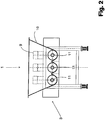
- FIGS. 1 to 3 show an embodiment of a device according to the invention for comminuting parts of any kind, which in concrete terms is a device for comminuting hollow plastic bodies, which are not shown in the figures. Regularly with such a device plastic bottles, such as PET bottles, crushed.
- the device comprises a feed device 1 and a comminution device 2.
- the feed device 1 comprises in the exemplary embodiment shown here a total of three conveyor units 3.
- the comminution device 2 comprises a tool-fitted rotor 4 which rotates within a housing 5.
- the housing 5, often referred to as a stator, is also equipped with tools 6.
- FIGS. 1 to 3 show common that the conveyor unit 3 conveys orthogonal to the rotor axis 7, wherein an arrangement in the range between 45 ° and 90 ° to the rotor axis 7 in accordance with the invention is possible.
- the figures further show a drive 8 of the rotor and drives 9 of the conveyor units 3.
- the drives 8, 9 are independent of each other, wherein it is advantageous to synchronize the drives 9 of the conveyor units 3.
- the material to be ground is output via a funnel 10 and is detected in the lower region of the funnel 10 by the conveyor units 3, which run parallel and equidistant from one another in a plane or extend towards the comminution device 2.
- the conveyor units 3 are designed as screw conveyors 11.
- the ground material is conveyed to the orthogonal to the screw conveyor 11 extending rotor 4 and is detected and ground by the local tools 12. Because of the tools 6 of the housing 5, the piece goods are already compressed and / or singulated, so that it reaches the area of the rotor 4 with reduced volume and can be shredded or shredded there by the tools 12.
- the figures also show that the rotor axis 7 lies approximately in the same plane as the axis of rotation 13 of the screw conveyors 11. This results in an extremely low height, whereby it is possible by the structural features to generate a significant mass flow, and this at a much lower level of tasks in the shredder than in conventional devices of the generic type.
Landscapes
- Engineering & Computer Science (AREA)
- Food Science & Technology (AREA)
- Crushing And Pulverization Processes (AREA)
- Screw Conveyors (AREA)
- Belt Conveyors (AREA)
- Processing And Handling Of Plastics And Other Materials For Molding In General (AREA)
- Filling Of Jars Or Cans And Processes For Cleaning And Sealing Jars (AREA)
- Disintegrating Or Milling (AREA)
Abstract
Description
- Die Erfindung betrifft eine Vorrichtung zum Zerkleinern von Teilen beliebiger Art, insbesondere von Kunststoffen, vorzugsweise von Kunststoffhohlkörpern wie zum Beispiel Kunststoffflaschen, mit einer Beschickungseinrichtung und einer Zerkleinerungseinrichtung, wobei die Beschickungseinrichtung mindestens eine Fördereinheit und die Zerkleinerungseinrichtung einen werkzeugbestückten Rotor umfasst, der innerhalb eines Gehäuses dreht.
- Vorrichtungen der gattungsbildenden Art sind sei Jahren in den unterschiedlichsten Ausführungsformen aus der Praxis bekannt. Lediglich beispielhaft wird dazu auf die
DE 38 13 879 verwiesen. Bei der dort bekannten Vorrichtung handelt es sich im Konkreten um eine Zerkleinerungsmaschine für thermoplastische Abfälle. Über einen Trichter wird das Mahlgut aufgegeben und gelangt unmittelbar von dem Trichter über eine Fördereinheit in die eigentliche Mühle, die einen in einem Gehäuse drehenden Rotor umfasst. Die Beschickungseinrichtung bzw. die Fördereinheit ist als Schnecke ausgeführt. Die Drehachsen von Schnecke und Rotor verlaufen parallel zueinander, so dass das Mahlgut über die Schnecke kopfseitig zu dem Rotor gelangt und dort von diesem erfasst werden muss. Dies ist insbesondere bei höheren Drehzahlen problematisch, da nämlich gerade leichtes Mahlgut, insbesondere Mahlgut aus Kunststoffhohlkörpern, dazu neigt, durch die Drehbewegung des Rotors zurückgeschlagen zu werden. Das Hineinfördern des Mahlguts in den Rotor ist daher äußerst problematisch. Außerdem hat man festgestellt, dass bei der bekannten Art des Hineinförderns von Mahlgut in den Bereich des Rotors ganz erhebliche Schallemissionen auftreten, die es stets zu reduzieren gilt. - Der vorliegenden Erfindung liegt daher die Aufgabe zugrunde, ein Vorrichtung zum Zerkleinern von Teilen beliebiger Art, insbesondere von Kunststoffen, vorzugsweise von Kunststoffhohlkörpern wie zum Beispiel Kunststoffflaschen, derart auszugestalten und weiterzubilden, dass im Bereich des Rotors eine hinreichend gute Materialannahme stattfindet, dass sich nämlich das Mahlgut mühelos in den Bereich des Rotors hineinfördern lässt. Arbeitsgeräusche sollen reduziert sein. Erfindungsgemäß wird die voranstehende Aufgabe durch die Merkmale des Patentanspruchs 1 gelöst. Danach ist die in Rede stehende Vorrichtung dadurch gekennzeichnet, dass die Fördereinheit zumindest im Bereich unmittelbar vor dem Rotor unter einem Winkel im Bereich zwischen 45° und 90° zu der Rotorachse fördert.
- In erfindungsgemäßer Weise ist zunächst einmal erkannt worden, dass die zuvor erörterten Probleme dadurch zu mindern sind, dass man von der bewährten parallelen Anordnung von Förderachse und Drehachse des Rotors abweicht, nämlich dadurch, dass die Fördereinheit zumindest im Bereich unmittelbar vor dem Rotor unter einem Winkel zwischen 45° und 90° zu der Rotorachse fördert. Dies hat den Vorteil, dass das Mahlgut gerade nicht parallel zur Drehbewegung des Rotors in dessen Bereich gefördert wird, wodurch das Mahlgut regelmäßig zurückschlägt und wodurch eine erhebliche Lärmemission auftritt. Ganz im Gegenteil wird hier ein ganz anderer Weg der Zuführung gewählt, nämlich unter einem Winkel im Bereich zwischen 45° und 90° zu der Rotorachse, vorzugsweise unter einem Winkel von etwa 90° zur Rotorachse. In bevorzugter Weise wird demnach das Mahlgut orthogonal zu der Drehachse des Rotors gefördert, so dass das Mahlgut entsprechend der Ausgestaltung des Rotors sowie der Ausgestaltung des darum angeordneten Gehäuses in idealer Weise aufgreifbar ist, nämlich entsprechend der Vorkehrung und Anordnung der Messer und/oder Schneidzähne.
- In vorteilhafter Weise sind mehrere Fördereinheiten vorgesehen, so dass das Mahlgut parallel zum Rotor förderbar ist, nämlich entsprechend der Breite der Zerkleinerungseinrichtung. Dabei lässt sich das Mahlgut über die gesamte Breite der Zerkleinerungseinrichtung fördern und der Zerkleinerungseinrichtung zuführen. Dies bewirkt einen ganz erheblichen Durchsatz.
- In weiter vorteilhafter Weise sind die Fördereinheiten äquidistant zueinander angeordnet. In weiter vorteilhafter Weise lassen sich die Abstände zwischen den einzelnen Fördereinheiten variieren. Ein besonderer Einstellmechanismus kann dazu vorgesehen sein.
- Grundsätzlich ist es denkbar, dass die Fördereinheiten parallel zueinander verlaufen. Ebenso ist es jedoch auch denkbar, den Verlauf der Fördereinheiten schräg zueinander, vorzugsweise unter einem spitzen Winkel zueinander, zu gestalten. Dabei könnte bereits beim Fördern eines voluminösen Mahlguts, beispielsweise beim Fördern von PET-Flaschen, bewerkstelligt werden, dass diese zumindest teilweise komprimiert bzw. deformiert oder gar aufgerissen werden.
- Die Fördereinheiten können im Wesentlichen in einer Ebene angeordnet sein. Will man das Mahlgut bereits während des Förderns mit Kräften beaufschlagen, kann es von weiterem Vorteil sein, die Fördereinheiten in unterschiedlichen Ebenen zueinander, möglichst schräg zueinander verlaufend, anzuordnen.
- In Bezug auf das Fördern des Mahlgutes ist es möglich, die Fördereinheiten im Wesentlichen waagrecht anzuordnen. Ebenso ist es denkbar, das Mahlgut vertikal oder unter einem beliebigen Winkel zwischen 0° und 180° zur Horizontalen der Zerkleinerungseinrichtung zuzuführen, und zwar je nach Bedarf. Dabei ist darauf zu achten, dass die Fördereinheit zumindest im Bereich unmittelbar vor dem Rotor den erforderlichen Winkel im Bereich zwischen 45°und 90°zu der Rotorachse hat.
- Es hat sich herausgestellt, dass die Materialannahme im Bereich der Zerkleinerungseinrichtung dann besonders gut ist, wenn die Längsachsen der Fördereinheiten unmittelbar mit der Rotorachse fluchten oder allenfalls geringfügig versetzt zur Rotorachse verlaufen. Dabei kann die Förderstrecke in verschiedene Förderabschnitte unterteilt sein, so dass das Mahlgut über die Förderstrecke hinweg in der Richtung umlenkbar ist.
- Die Fördereinheit ist als Förderschnecke ausgeführt. Mehrere Förderschnecken können als Fördereinheiten vorgesehen sein. Dabei sollten die Förderschnecken so gegeneinander wirken, dass sie ein das Fördergut einziehendes Verhalten haben. Entsprechend sind die Drehrichtung und die Ausgestaltung der Förderschnecken aufeinander abzustimmen.
- Entsprechend der konkreten Ausgestaltung der Förderschnecken können diese gleichsinnig oder aber gegensinnig drehen. Die Förderschnecken können auf unterschiedliche Art gelagert sein, so beispielsweise fliegend oder beidseits mit jeweils einem Gegenlager.
- Insbesondere im Hinblick auf einen störungsfreien Zerkleinerungsprozess bei optimalem Durchsatz ist es von Vorteil, wenn die Drehzahl der Förderschnecken vorzugsweise unter Berücksichtigung der Lastaufnahme des Antriebs geregelt ist. Außerdem könnte eine umfassende Sensorik vorgesehen sein, die die Drehzahl unter Berücksichtigung sonstiger Faktoren beeinflusst.
- Die Förderschnecken können zumindest teilweise mit Werkzeugen bestückt sein, wobei die Werkzeuge der Förderschnecken als Messer und/oder Reißzähne ausgeführt sein können. Die Vorkehrung von Reißzähnen dient zur Vereinzelung zusammenhängender Teile und hilft ganze Ballen von Material aufzulösen.
- Im Hinblick auf einen störungsfreien Betrieb ist es von weiterem Vorteil, wenn die Förderschnecken über eine Reversiersteuerung rückwärts drehbar sind. Materialstaus bzw. Verstopfungen lassen sich dadurch mühelos auflösen.
- Des Weiteren sei erwähnt, dass das Mahlgut auf beliebige Weise der Fördereinheit zuführbar ist. Im Hinblick auf eine besonders einfache Ausgestaltung ist der Fördereinheit ein Trichter zur Aufgabe des Mahlguts vorgebaut. Beliebige sonstige Ausgestaltungen zum Zwecke der Aufgabe des Mahlguts sind realisierbar.
- Die Zerkleinerungseinheit kann grundsätzlich sehr unterschiedlich ausgeführt sein, so beispielsweise als Schneidmühle, Hammermühle, Schredder, etc. Unterschiedliche weitere Ausgestaltungen, insbesondere im Detail, sind denkbar.
- Im Lichte der voranstehenden Ausführungen lässt sich festhalten, dass sich die erfindungsgemäße Vorrichtung insbesondere zum Zerkleinern leichter Materialien, vorzugsweise zum Zerkleinern von Kunststoff-Hohlkörpern, besonders eignet. Dies ist nicht zuletzt auf die bessere Materialannahme im Bereich der Zerkleinerungseinrichtung zurückzuführen. Aufgrund der besonderen Anordnung der Beschickungseinrichtung zur Drehrichtung des Rotors ist nicht nur die Materialannahme begünstigt, sondern sind vor allem auch Schallemissionen reduziert. Ein weiterer Vorteil ist darin zu sehen, dass die Aufgabehöhe in der erfindungsgemäßen Vorrichtung geringer ist als bei herkömmlichen Zerkleinerern, wodurch sich eine bessere Möglichkeit des An- bzw. Einbaus im Bereich einer Fertigung ergibt.
- Es gibt nun verschiedene Möglichkeiten, die Lehre der vorliegenden Erfindung in vorteilhafter Weise auszugestalten und weiterzubilden. Dazu ist einerseits auf die dem Patentanspruch 1 nachgeordneten Patentansprüche und andererseits auf die nachfolgende Erläuterung eines bevorzugten Ausführungsbeispiels der Erfindung anhand der Zeichnung zu verweisen. In Verbindung mit der Erläuterung des bevorzugten Ausführungsbeispiels der Erfindung anhand der Zeichnung werden auch im Allgemeinen bevorzugte Ausgestaltungen und Weiterbildungen der Lehre erläutert. In der Zeichnung zeigt
- Fig. 1
- in einer schematischen Seitenansicht ein Ausführungsbeispiel einer erfindungsgemäßen Vorrichtung,
- Fig. 2
- den Gegenstand aus
Fig. 1 im Querschnitt durch die Beschickungseinrichtung und - Fig. 3
- den Gegenstand aus
Fig. 1 in einer schematischen Draufsicht. - Die
Figuren 1 bis 3 zeigen ein Ausführungsbeispiel einer erfindungsgemäßen Vorrichtung zum Zerkleinern von Teilen beliebiger Art, wobei es sich hier im Konkreten um eine Vorrichtung zum Zerkleinern von Kunststoffhohlkörpern handelt, die in den Figuren nicht gezeigt sind. Regelmäßig werden mit einer solchen Vorrichtung Kunststoffflaschen, so beispielsweise PET-Flaschen, zerkleinert. Die Vorrichtung umfasst eine Beschickungseinrichtung 1 und eine Zerkleinerungseinrichtung 2. Die Beschickungseinrichtung 1 umfasst bei dem hier gezeigten Ausführungsbeispiel insgesamt drei Fördereinheiten 3. Die Zerkleinerungseinrichtung 2 umfasst einen werkzeugbestückten Rotor 4, der innerhalb eines Gehäuses 5 dreht. Das Gehäuse 5, oft auch als Stator bezeichnet, ist ebenfalls mit Werkzeugen 6 ausgestattet. - Die
Figuren 1 bis 3 zeigen gemeinsamen, dass die Fördereinheit 3 orthogonal zu der Rotorachse 7 fördert, wobei eine Anordnung im Bereich zwischen 45° und 90° zur Rotorachse 7 in erfindungsgemäßer Weise möglich ist. - Die Figuren zeigen des Weiteren einen Antrieb 8 des Rotors und Antriebe 9 der Fördereinheiten 3. Die Antriebe 8, 9 sind unabhängig voneinander, wobei es von Vorteil ist, die Antriebe 9 der Fördereinheiten 3 zu synchronisieren.
- Das Mahlgut wird über einen Trichter 10 ausgegeben und wird im unteren Bereich des Trichters 10 von den Fördereinheiten 3 erfasst, die parallel und äquidistant zueinander in einer Ebene verlaufen bzw. sich zur Zerkleinerungseinrichtung 2 hin erstrecken. Die Fördereinheiten 3 sind als Förderschnecken 11 ausgeführt.
- In der vollen Breite der drei nebeneinander arbeitenden Förderschnecken 11 wird das Mahlgut zu dem sich orthogonal zu den Förderschnecken 11 erstreckenden Rotor 4 gefördert und wird von den dortigen Werkzeugen 12 erfasst und gemahlen. Aufgrund der Werkzeuge 6 des Gehäuses 5 ist das Stückgut bereits zusammengedrückt und/oder vereinzelt, so dass es mit reduziertem Volumen in den Bereich des Rotors 4 gelangt und dort durch die Werkzeuge 12 zerkleinert bzw. geschreddert werden kann.
- Die Figuren lassen des Weiteren erkennen, dass die Rotorachse 7 in etwa auf dergleichen Ebene wie die Drehachse 13 der Förderschnecken 11 liegt. Daraus resultiert eine äußerst geringe Bauhöhe, wobei es durch die konstruktiven Merkmale möglich ist, einen erheblichen Massendurchsatz zu generieren, und dies bei wesentlich geringerer Aufgabenhöhe in den Zerkleinerer als bei herkömmlichen Geräten der gattungsbildenden Art.
- In Bezug auf Merkmale, die sich den Figuren nicht entnehmen lassen, sei zur Vermeidung von Wiederholungen auf den allgemeinen Teil der Beschreibung verwiesen.
- Schließlich sei angemerkt, dass das voranstehend erörterte Ausführungsbeispiel lediglich der beispielhaften Erörterung der beanspruchten Lehre dient, diese jedoch nicht auf das Ausführungsbeispiel einschränkt.
Claims (3)
- Vorrichtung zum Zerkleinern von Teilen beliebiger Art, insbesondere von Kunststoffen, vorzugsweise von Kunststoffhohlkörpern wie zum Beispiel Kunststoffflaschen, mit einer Beschickungseinrichtung (1) und einer Zerkleinerungseinrichtung (2), wobei die Beschickungseinrichtung (1) mindestens eine Fördereinheit (3) und die Zerkleinerungseinrichtung (2) einen werkzeugbestückten Rotor (4) umfasst, der innerhalb eines Gehäuses (5) dreht,
dadurch gekennzeichnet, dass die Fördereinheit (3) zumindest im Bereich unmittelbar vor dem Rotor (4) unter einem Winkel im Bereich zwischen 45° und 90° zu der Rotorachse (7) fördert und dass die Fördereinheit (3) als Förderschnecke (11) ausgeführt ist. - Vorrichtung nach Anspruch 1, dadurch gekennzeichnet, dass die Förderschnecke (11) zumindest teilweise mit Werkzeugen bestückt ist.
- Vorrichtung nach Anspruch 2, dadurch gekennzeichnet, dass die Werkzeuge als Messer und/oder Reißzähne ausgeführt sind.
Priority Applications (1)
| Application Number | Priority Date | Filing Date | Title |
|---|---|---|---|
| PL12156916T PL2468409T3 (pl) | 2006-01-24 | 2007-01-08 | Urządzenie do rozdrabniania części dowolnego rodzaju |
Applications Claiming Priority (2)
| Application Number | Priority Date | Filing Date | Title |
|---|---|---|---|
| DE102006003529A DE102006003529A1 (de) | 2006-01-24 | 2006-01-24 | Vorrichtung zum Zerkleinern von Teilen beliebiger Art |
| EP07711127.6A EP1979099B1 (de) | 2006-01-24 | 2007-01-08 | Vorrichtung zum zerkleinern von teilen beliebiger art |
Related Parent Applications (2)
| Application Number | Title | Priority Date | Filing Date |
|---|---|---|---|
| EP07711127.6 Division | 2007-01-08 | ||
| EP07711127.6A Division EP1979099B1 (de) | 2006-01-24 | 2007-01-08 | Vorrichtung zum zerkleinern von teilen beliebiger art |
Publications (2)
| Publication Number | Publication Date |
|---|---|
| EP2468409A1 true EP2468409A1 (de) | 2012-06-27 |
| EP2468409B1 EP2468409B1 (de) | 2015-07-15 |
Family
ID=37969577
Family Applications (3)
| Application Number | Title | Priority Date | Filing Date |
|---|---|---|---|
| EP12156911.5A Revoked EP2468410B1 (de) | 2006-01-24 | 2007-01-08 | Vorrichtung zum Zerkleinern von Teilen beliebiger Art |
| EP12156916.4A Not-in-force EP2468409B1 (de) | 2006-01-24 | 2007-01-08 | Vorrichtung zum Zerkleinern von Teilen beliebiger Art |
| EP07711127.6A Revoked EP1979099B1 (de) | 2006-01-24 | 2007-01-08 | Vorrichtung zum zerkleinern von teilen beliebiger art |
Family Applications Before (1)
| Application Number | Title | Priority Date | Filing Date |
|---|---|---|---|
| EP12156911.5A Revoked EP2468410B1 (de) | 2006-01-24 | 2007-01-08 | Vorrichtung zum Zerkleinern von Teilen beliebiger Art |
Family Applications After (1)
| Application Number | Title | Priority Date | Filing Date |
|---|---|---|---|
| EP07711127.6A Revoked EP1979099B1 (de) | 2006-01-24 | 2007-01-08 | Vorrichtung zum zerkleinern von teilen beliebiger art |
Country Status (8)
| Country | Link |
|---|---|
| US (1) | US7793872B2 (de) |
| EP (3) | EP2468410B1 (de) |
| CN (1) | CN101374604B (de) |
| DE (1) | DE102006003529A1 (de) |
| ES (1) | ES2436543T3 (de) |
| HU (2) | HUE026417T2 (de) |
| PL (3) | PL2468409T3 (de) |
| WO (1) | WO2007085221A2 (de) |
Families Citing this family (11)
| Publication number | Priority date | Publication date | Assignee | Title |
|---|---|---|---|---|
| CN101987485B (zh) * | 2009-07-30 | 2013-03-20 | 王昌佑 | 自动高效率塑料粉碎机 |
| DE102010036761A1 (de) * | 2010-07-30 | 2012-02-02 | Mewa Recycling Maschinen Und Anlagenbau Gmbh | Zerkleinerungsvorrichtung mit Schneckenförderer |
| DE202010014764U1 (de) * | 2010-10-31 | 2012-02-01 | Weima Maschinenbau Gmbh | Zerkleinerungsmaschine |
| NL2006398C2 (nl) * | 2011-03-15 | 2012-09-18 | Metaalwerk Arie Belo B V | Inrichting voor het verkleinen van plantaardige producten alsmede werkwijzen voor het bedrijven van een dergelijke inrichting. |
| CN102275181A (zh) * | 2011-06-08 | 2011-12-14 | 潍坊金丝达实业有限公司 | 冲切式垃圾破碎机 |
| CN102397811A (zh) * | 2011-11-21 | 2012-04-04 | 张家港市亿利机械有限公司 | 带强制喂料装置的破碎机 |
| CN103316749A (zh) * | 2013-06-24 | 2013-09-25 | 四川治源环保成套设备有限责任公司 | 一种垃圾粉碎机 |
| CN103357475A (zh) * | 2013-07-25 | 2013-10-23 | 姜堰市通源机械厂 | 一种餐厨废弃物破碎机 |
| CN103406190A (zh) * | 2013-08-23 | 2013-11-27 | 南昌光明化验设备有限公司 | 一种具有自动输送及出料功能的粉碎机 |
| ES1209488Y (es) * | 2018-03-12 | 2018-07-03 | Talleres Zb S A | Fragmentadora movil de materiales metalicos con seguridad mejorada |
| DE102020113926B4 (de) * | 2020-05-25 | 2025-05-28 | Fraunhofer-Gesellschaft zur Förderung der angewandten Forschung eingetragener Verein | Verfahren zur Herstellung einer Folie mit Funktionsbeschichtung |
Citations (4)
| Publication number | Priority date | Publication date | Assignee | Title |
|---|---|---|---|---|
| DE3813879A1 (de) | 1985-09-02 | 1989-11-02 | Thomas Peter Dipl Ing Madeiski | Zerkleinerungsmaschine fuer thermoplastabfaelle |
| DE29610848U1 (de) * | 1996-06-20 | 1996-10-17 | WANNER-Technik GmbH, 97877 Wertheim | Feststoffmühle |
| US5601239A (en) * | 1995-07-05 | 1997-02-11 | Wood Waste Energy, Inc. | Bulk material shredder and method |
| WO2002022270A1 (en) * | 2000-09-12 | 2002-03-21 | Positive Impact Waste Solutions, Inc. | Apparatus for processing medical waste |
Family Cites Families (15)
| Publication number | Priority date | Publication date | Assignee | Title |
|---|---|---|---|---|
| US850988A (en) * | 1905-11-24 | 1907-04-23 | Williams Patent Crusher & Pulv | Coal-crusher. |
| US1711464A (en) | 1927-02-10 | 1929-04-30 | Ruprecht Louis | Grinding machine |
| US2128194A (en) * | 1935-06-12 | 1938-08-23 | Louis Ruprecht | Reducing mill |
| DE2260688C3 (de) | 1972-12-12 | 1978-03-23 | Kloeckner-Humboldt-Deutz Ag, 5000 Koeln | Vorrichtung zur Regelung der Antriebsdrehzahl eines einer Zerkleinerungsmaschine Gut zuführenden Förderers |
| US4037799A (en) * | 1975-04-30 | 1977-07-26 | Feedmobile, Inc. | Portable hammermill and attached inclined augered feed table |
| US4205794A (en) * | 1978-09-18 | 1980-06-03 | Horton Jack E | Destructive device |
| DD149780A1 (de) * | 1980-03-12 | 1981-07-29 | Eberhard Aurich | Anordnung zum zerkleinern flaechiger und/oder flaechenstueckiger werkstoffreste |
| DE3517684C2 (de) * | 1985-05-14 | 1994-02-17 | Werner Doppstadt | Kompostiergerät zum Zerkleinern von organischem Abfall |
| DE8816651U1 (de) | 1988-10-06 | 1990-02-15 | Hans Brochier GmbH & Co, 90482 Nürnberg | Schneckenförderer |
| US4932595A (en) | 1989-02-22 | 1990-06-12 | John Brown Inc. | Size reduction system for plastic articles |
| AT407234B (de) | 1996-10-14 | 2001-01-25 | Gerold Ing Barth | Aufbereitungsvorrichtung zum zerkleinern und fördern von thermoplastischem kunststoffmaterial |
| DE19756670C2 (de) | 1997-06-12 | 2000-02-17 | Dornhan Maschf Gmbh | Einzugs-, Stütz- und Lagervorrichtung für Zerkleinerungsmaschinen |
| DE19748206A1 (de) * | 1997-11-03 | 1999-05-06 | Vkw Vogel & Mueller Ges M B H | Verfahren zum Betrieb eines Mischers und Zerkleinerers für Abfälle, insbesondere für biologisch abbaubare Abfälle und ein nach dem Verfahren arbeitender Zerkleinerer und Mischer |
| GB2390043A (en) * | 2002-06-28 | 2003-12-31 | Clubbs Projects Ltd | Shredding apparatus to facilitate the burning of bales of packaging material |
| DE10234763A1 (de) | 2002-07-30 | 2004-02-12 | Mathias Falkenberg | Verfahren und Vorrichtung zum Zerkleinern von Schüttgut |
-
2006
- 2006-01-24 DE DE102006003529A patent/DE102006003529A1/de not_active Withdrawn
-
2007
- 2007-01-08 US US12/162,111 patent/US7793872B2/en active Active
- 2007-01-08 PL PL12156916T patent/PL2468409T3/pl unknown
- 2007-01-08 ES ES07711127.6T patent/ES2436543T3/es active Active
- 2007-01-08 WO PCT/DE2007/000030 patent/WO2007085221A2/de not_active Ceased
- 2007-01-08 HU HUE12156911A patent/HUE026417T2/en unknown
- 2007-01-08 EP EP12156911.5A patent/EP2468410B1/de not_active Revoked
- 2007-01-08 CN CN200780003795XA patent/CN101374604B/zh not_active Expired - Fee Related
- 2007-01-08 PL PL07711127T patent/PL1979099T3/pl unknown
- 2007-01-08 EP EP12156916.4A patent/EP2468409B1/de not_active Not-in-force
- 2007-01-08 PL PL12156911T patent/PL2468410T3/pl unknown
- 2007-01-08 EP EP07711127.6A patent/EP1979099B1/de not_active Revoked
- 2007-01-08 HU HUE12156916A patent/HUE026272T2/en unknown
Patent Citations (4)
| Publication number | Priority date | Publication date | Assignee | Title |
|---|---|---|---|---|
| DE3813879A1 (de) | 1985-09-02 | 1989-11-02 | Thomas Peter Dipl Ing Madeiski | Zerkleinerungsmaschine fuer thermoplastabfaelle |
| US5601239A (en) * | 1995-07-05 | 1997-02-11 | Wood Waste Energy, Inc. | Bulk material shredder and method |
| DE29610848U1 (de) * | 1996-06-20 | 1996-10-17 | WANNER-Technik GmbH, 97877 Wertheim | Feststoffmühle |
| WO2002022270A1 (en) * | 2000-09-12 | 2002-03-21 | Positive Impact Waste Solutions, Inc. | Apparatus for processing medical waste |
Also Published As
| Publication number | Publication date |
|---|---|
| PL2468410T3 (pl) | 2015-12-31 |
| EP2468410B1 (de) | 2015-07-15 |
| CN101374604A (zh) | 2009-02-25 |
| EP1979099B1 (de) | 2013-09-11 |
| EP2468409B1 (de) | 2015-07-15 |
| WO2007085221A3 (de) | 2007-11-15 |
| PL2468409T3 (pl) | 2015-12-31 |
| CN101374604B (zh) | 2013-02-20 |
| US20090050724A1 (en) | 2009-02-26 |
| EP2468410A1 (de) | 2012-06-27 |
| EP1979099A2 (de) | 2008-10-15 |
| DE102006003529A1 (de) | 2007-08-09 |
| HUE026272T2 (en) | 2016-06-28 |
| HUE026417T2 (en) | 2016-05-30 |
| US7793872B2 (en) | 2010-09-14 |
| ES2436543T3 (es) | 2014-01-02 |
| WO2007085221A2 (de) | 2007-08-02 |
| PL1979099T3 (pl) | 2014-03-31 |
Similar Documents
| Publication | Publication Date | Title |
|---|---|---|
| EP2468409B1 (de) | Vorrichtung zum Zerkleinern von Teilen beliebiger Art | |
| EP2857103B1 (de) | Zerkleinerungsvorrichtung | |
| DE10353188B4 (de) | Vorrichtung zum Zerkleinern leerer Behälter | |
| DE19612024C2 (de) | Zerkleinerungsgerät | |
| EP3352961A1 (de) | Vorrichtung und verfahren zur verarbeitung von thermoplastischem kunststoff mit einer blasvorrichtung für eine transportschnecke | |
| DE4341606A1 (de) | Vorrichtung zum Schneiden von Fleisch | |
| EP3394338B1 (de) | Vorrichtung und verfahren zum verarbeiten eines in einem stofflöser gebildeten zopfs | |
| EP3215273B1 (de) | Vernichtung von beschriftetem papier | |
| DE102013202454B4 (de) | Vorrichtung zum Homogenisieren von Holzhackschnitzeln | |
| DE202006001147U1 (de) | Vorrichtung zum Zerkleinern von Teilen beliebiger Art | |
| EP1903852B1 (de) | Zerkleinerungsvorrichtung mit zumindest einem rotor und zumindest einer gegenschneide zur zerkleinerung von organischen materialien | |
| DE102006034150B4 (de) | Rohstoffannahme-, Druck- und Förderschneckensystem für Lebensmittelzerkleinerungsmaschinen | |
| EP1151799A1 (de) | Zerkleinerungswalze | |
| EP0753347A1 (de) | Einrichtung zum Zerkleinern harter Materialien, vorzugsweise biogener Abfälle | |
| DE202007006712U1 (de) | Schrauben-Nachdrückeinrichtung für Zerkleinerungseinrichtung | |
| DE202007002423U1 (de) | Holzzerkleinerer mit rotierenden Schneidmessern | |
| DE19548883C2 (de) | Langsamlaufender Gartenhäcksler | |
| EP0955098A1 (de) | Vorrichtung zu Zerkleinern von Gegenständen | |
| EP4082945B1 (de) | Auflöseeinheit und verfahren zum auflösen von schüttgut | |
| WO2014173384A1 (de) | Vorrichtung zur zerkleinerung von stückigen reststoffen der palmölgewinnung | |
| EP0760256B1 (de) | Zerkleinerungsgerät | |
| DE9321105U1 (de) | Vorrichtung zum Schneiden von Fleisch | |
| AT412387B (de) | Vorrichtung zum zerkleinern von gebinden | |
| DE4434548A1 (de) | Einrichtung zur Aufbereitung von Material | |
| AT527439A1 (de) | Aufbereitungsanlage für Kunststoffmaterial |
Legal Events
| Date | Code | Title | Description |
|---|---|---|---|
| AC | Divisional application: reference to earlier application |
Ref document number: 1979099 Country of ref document: EP Kind code of ref document: P |
|
| AK | Designated contracting states |
Kind code of ref document: A1 Designated state(s): AT BE BG CH CY CZ DE DK EE ES FI FR GB GR HU IE IS IT LI LT LU LV MC NL PL PT RO SE SI SK TR |
|
| PUAI | Public reference made under article 153(3) epc to a published international application that has entered the european phase |
Free format text: ORIGINAL CODE: 0009012 |
|
| 17P | Request for examination filed |
Effective date: 20120910 |
|
| GRAP | Despatch of communication of intention to grant a patent |
Free format text: ORIGINAL CODE: EPIDOSNIGR1 |
|
| RIC1 | Information provided on ipc code assigned before grant |
Ipc: B02C 18/22 20060101AFI20150129BHEP Ipc: B02C 25/00 20060101ALN20150129BHEP |
|
| INTG | Intention to grant announced |
Effective date: 20150224 |
|
| GRAS | Grant fee paid |
Free format text: ORIGINAL CODE: EPIDOSNIGR3 |
|
| GRAA | (expected) grant |
Free format text: ORIGINAL CODE: 0009210 |
|
| AC | Divisional application: reference to earlier application |
Ref document number: 1979099 Country of ref document: EP Kind code of ref document: P |
|
| AK | Designated contracting states |
Kind code of ref document: B1 Designated state(s): AT BE BG CH CY CZ DE DK EE ES FI FR GB GR HU IE IS IT LI LT LU LV MC NL PL PT RO SE SI SK TR |
|
| REG | Reference to a national code |
Ref country code: CH Ref legal event code: EP Ref country code: GB Ref legal event code: FG4D Free format text: NOT ENGLISH |
|
| REG | Reference to a national code |
Ref country code: IE Ref legal event code: FG4D Free format text: LANGUAGE OF EP DOCUMENT: GERMAN |
|
| REG | Reference to a national code |
Ref country code: AT Ref legal event code: REF Ref document number: 736498 Country of ref document: AT Kind code of ref document: T Effective date: 20150815 |
|
| REG | Reference to a national code |
Ref country code: DE Ref legal event code: R096 Ref document number: 502007014069 Country of ref document: DE |
|
| REG | Reference to a national code |
Ref country code: SE Ref legal event code: TRGR |
|
| REG | Reference to a national code |
Ref country code: RO Ref legal event code: EPE |
|
| REG | Reference to a national code |
Ref country code: NL Ref legal event code: FP |
|
| REG | Reference to a national code |
Ref country code: LT Ref legal event code: MG4D |
|
| REG | Reference to a national code |
Ref country code: PL Ref legal event code: T3 |
|
| REG | Reference to a national code |
Ref country code: FR Ref legal event code: PLFP Year of fee payment: 10 |
|
| PG25 | Lapsed in a contracting state [announced via postgrant information from national office to epo] |
Ref country code: LV Free format text: LAPSE BECAUSE OF FAILURE TO SUBMIT A TRANSLATION OF THE DESCRIPTION OR TO PAY THE FEE WITHIN THE PRESCRIBED TIME-LIMIT Effective date: 20150715 Ref country code: FI Free format text: LAPSE BECAUSE OF FAILURE TO SUBMIT A TRANSLATION OF THE DESCRIPTION OR TO PAY THE FEE WITHIN THE PRESCRIBED TIME-LIMIT Effective date: 20150715 Ref country code: GR Free format text: LAPSE BECAUSE OF FAILURE TO SUBMIT A TRANSLATION OF THE DESCRIPTION OR TO PAY THE FEE WITHIN THE PRESCRIBED TIME-LIMIT Effective date: 20151016 Ref country code: LT Free format text: LAPSE BECAUSE OF FAILURE TO SUBMIT A TRANSLATION OF THE DESCRIPTION OR TO PAY THE FEE WITHIN THE PRESCRIBED TIME-LIMIT Effective date: 20150715 |
|
| PG25 | Lapsed in a contracting state [announced via postgrant information from national office to epo] |
Ref country code: ES Free format text: LAPSE BECAUSE OF FAILURE TO SUBMIT A TRANSLATION OF THE DESCRIPTION OR TO PAY THE FEE WITHIN THE PRESCRIBED TIME-LIMIT Effective date: 20150715 Ref country code: PT Free format text: LAPSE BECAUSE OF FAILURE TO SUBMIT A TRANSLATION OF THE DESCRIPTION OR TO PAY THE FEE WITHIN THE PRESCRIBED TIME-LIMIT Effective date: 20151116 |
|
| PGFP | Annual fee paid to national office [announced via postgrant information from national office to epo] |
Ref country code: RO Payment date: 20151229 Year of fee payment: 10 Ref country code: PL Payment date: 20151228 Year of fee payment: 10 |
|
| REG | Reference to a national code |
Ref country code: DE Ref legal event code: R026 Ref document number: 502007014069 Country of ref document: DE |
|
| PLBI | Opposition filed |
Free format text: ORIGINAL CODE: 0009260 |
|
| PG25 | Lapsed in a contracting state [announced via postgrant information from national office to epo] |
Ref country code: IT Free format text: LAPSE BECAUSE OF FAILURE TO SUBMIT A TRANSLATION OF THE DESCRIPTION OR TO PAY THE FEE WITHIN THE PRESCRIBED TIME-LIMIT Effective date: 20150715 Ref country code: DK Free format text: LAPSE BECAUSE OF FAILURE TO SUBMIT A TRANSLATION OF THE DESCRIPTION OR TO PAY THE FEE WITHIN THE PRESCRIBED TIME-LIMIT Effective date: 20150715 Ref country code: CZ Free format text: LAPSE BECAUSE OF FAILURE TO SUBMIT A TRANSLATION OF THE DESCRIPTION OR TO PAY THE FEE WITHIN THE PRESCRIBED TIME-LIMIT Effective date: 20150715 Ref country code: SK Free format text: LAPSE BECAUSE OF FAILURE TO SUBMIT A TRANSLATION OF THE DESCRIPTION OR TO PAY THE FEE WITHIN THE PRESCRIBED TIME-LIMIT Effective date: 20150715 Ref country code: EE Free format text: LAPSE BECAUSE OF FAILURE TO SUBMIT A TRANSLATION OF THE DESCRIPTION OR TO PAY THE FEE WITHIN THE PRESCRIBED TIME-LIMIT Effective date: 20150715 |
|
| PGFP | Annual fee paid to national office [announced via postgrant information from national office to epo] |
Ref country code: IE Payment date: 20160125 Year of fee payment: 10 |
|
| 26 | Opposition filed |
Opponent name: STF MASCHINEN- UND ANLAGENBAU GMBH Effective date: 20160407 Opponent name: NEUE HERBOLD MASCHINEN- UND ANLAGENBAU GMBH Effective date: 20160408 |
|
| PLAX | Notice of opposition and request to file observation + time limit sent |
Free format text: ORIGINAL CODE: EPIDOSNOBS2 |
|
| PGFP | Annual fee paid to national office [announced via postgrant information from national office to epo] |
Ref country code: HU Payment date: 20151229 Year of fee payment: 10 |
|
| REG | Reference to a national code |
Ref country code: HU Ref legal event code: AG4A Ref document number: E026272 Country of ref document: HU |
|
| PG25 | Lapsed in a contracting state [announced via postgrant information from national office to epo] |
Ref country code: SI Free format text: LAPSE BECAUSE OF FAILURE TO SUBMIT A TRANSLATION OF THE DESCRIPTION OR TO PAY THE FEE WITHIN THE PRESCRIBED TIME-LIMIT Effective date: 20150715 Ref country code: LU Free format text: LAPSE BECAUSE OF FAILURE TO SUBMIT A TRANSLATION OF THE DESCRIPTION OR TO PAY THE FEE WITHIN THE PRESCRIBED TIME-LIMIT Effective date: 20160108 |
|
| PLBB | Reply of patent proprietor to notice(s) of opposition received |
Free format text: ORIGINAL CODE: EPIDOSNOBS3 |
|
| PG25 | Lapsed in a contracting state [announced via postgrant information from national office to epo] |
Ref country code: MC Free format text: LAPSE BECAUSE OF FAILURE TO SUBMIT A TRANSLATION OF THE DESCRIPTION OR TO PAY THE FEE WITHIN THE PRESCRIBED TIME-LIMIT Effective date: 20150715 |
|
| REG | Reference to a national code |
Ref country code: FR Ref legal event code: PLFP Year of fee payment: 11 |
|
| PG25 | Lapsed in a contracting state [announced via postgrant information from national office to epo] |
Ref country code: RO Free format text: LAPSE BECAUSE OF NON-PAYMENT OF DUE FEES Effective date: 20170108 |
|
| REG | Reference to a national code |
Ref country code: IE Ref legal event code: MM4A |
|
| PG25 | Lapsed in a contracting state [announced via postgrant information from national office to epo] |
Ref country code: HU Free format text: LAPSE BECAUSE OF NON-PAYMENT OF DUE FEES Effective date: 20170109 |
|
| REG | Reference to a national code |
Ref country code: FR Ref legal event code: PLFP Year of fee payment: 12 |
|
| PG25 | Lapsed in a contracting state [announced via postgrant information from national office to epo] |
Ref country code: IE Free format text: LAPSE BECAUSE OF NON-PAYMENT OF DUE FEES Effective date: 20170108 |
|
| RDAF | Communication despatched that patent is revoked |
Free format text: ORIGINAL CODE: EPIDOSNREV1 |
|
| STAA | Information on the status of an ep patent application or granted ep patent |
Free format text: STATUS: THE PATENT HAS BEEN GRANTED |
|
| APBM | Appeal reference recorded |
Free format text: ORIGINAL CODE: EPIDOSNREFNO |
|
| APBP | Date of receipt of notice of appeal recorded |
Free format text: ORIGINAL CODE: EPIDOSNNOA2O |
|
| APAH | Appeal reference modified |
Free format text: ORIGINAL CODE: EPIDOSCREFNO |
|
| APBQ | Date of receipt of statement of grounds of appeal recorded |
Free format text: ORIGINAL CODE: EPIDOSNNOA3O |
|
| PG25 | Lapsed in a contracting state [announced via postgrant information from national office to epo] |
Ref country code: CY Free format text: LAPSE BECAUSE OF FAILURE TO SUBMIT A TRANSLATION OF THE DESCRIPTION OR TO PAY THE FEE WITHIN THE PRESCRIBED TIME-LIMIT Effective date: 20150715 |
|
| PG25 | Lapsed in a contracting state [announced via postgrant information from national office to epo] |
Ref country code: IS Free format text: LAPSE BECAUSE OF FAILURE TO SUBMIT A TRANSLATION OF THE DESCRIPTION OR TO PAY THE FEE WITHIN THE PRESCRIBED TIME-LIMIT Effective date: 20150715 Ref country code: TR Free format text: LAPSE BECAUSE OF FAILURE TO SUBMIT A TRANSLATION OF THE DESCRIPTION OR TO PAY THE FEE WITHIN THE PRESCRIBED TIME-LIMIT Effective date: 20150715 |
|
| PG25 | Lapsed in a contracting state [announced via postgrant information from national office to epo] |
Ref country code: PL Free format text: LAPSE BECAUSE OF NON-PAYMENT OF DUE FEES Effective date: 20170108 |
|
| APBU | Appeal procedure closed |
Free format text: ORIGINAL CODE: EPIDOSNNOA9O |
|
| PGFP | Annual fee paid to national office [announced via postgrant information from national office to epo] |
Ref country code: GB Payment date: 20190124 Year of fee payment: 13 Ref country code: FR Payment date: 20190122 Year of fee payment: 13 Ref country code: DE Payment date: 20190327 Year of fee payment: 13 Ref country code: NL Payment date: 20190122 Year of fee payment: 13 Ref country code: BG Payment date: 20190123 Year of fee payment: 13 Ref country code: CH Payment date: 20190124 Year of fee payment: 13 |
|
| PGFP | Annual fee paid to national office [announced via postgrant information from national office to epo] |
Ref country code: SE Payment date: 20190124 Year of fee payment: 13 Ref country code: BE Payment date: 20190122 Year of fee payment: 13 Ref country code: AT Payment date: 20190118 Year of fee payment: 13 |
|
| PLAY | Examination report in opposition despatched + time limit |
Free format text: ORIGINAL CODE: EPIDOSNORE2 |
|
| PLBC | Reply to examination report in opposition received |
Free format text: ORIGINAL CODE: EPIDOSNORE3 |
|
| RDAD | Information modified related to despatch of communication that patent is revoked |
Free format text: ORIGINAL CODE: EPIDOSCREV1 |
|
| REG | Reference to a national code |
Ref country code: DE Ref legal event code: R119 Ref document number: 502007014069 Country of ref document: DE |
|
| REG | Reference to a national code |
Ref country code: CH Ref legal event code: PL |
|
| REG | Reference to a national code |
Ref country code: SE Ref legal event code: EUG |
|
| REG | Reference to a national code |
Ref country code: NL Ref legal event code: MM Effective date: 20200201 |
|
| REG | Reference to a national code |
Ref country code: AT Ref legal event code: MM01 Ref document number: 736498 Country of ref document: AT Kind code of ref document: T Effective date: 20200108 |
|
| GBPC | Gb: european patent ceased through non-payment of renewal fee |
Effective date: 20200108 |
|
| REG | Reference to a national code |
Ref country code: SE Ref legal event code: EUG |
|
| REG | Reference to a national code |
Ref country code: BE Ref legal event code: MM Effective date: 20200131 |
|
| PG25 | Lapsed in a contracting state [announced via postgrant information from national office to epo] |
Ref country code: GB Free format text: LAPSE BECAUSE OF NON-PAYMENT OF DUE FEES Effective date: 20200108 Ref country code: FR Free format text: LAPSE BECAUSE OF NON-PAYMENT OF DUE FEES Effective date: 20200131 Ref country code: NL Free format text: LAPSE BECAUSE OF NON-PAYMENT OF DUE FEES Effective date: 20200201 Ref country code: DE Free format text: LAPSE BECAUSE OF NON-PAYMENT OF DUE FEES Effective date: 20200801 Ref country code: SE Free format text: LAPSE BECAUSE OF NON-PAYMENT OF DUE FEES Effective date: 20200109 |
|
| PG25 | Lapsed in a contracting state [announced via postgrant information from national office to epo] |
Ref country code: BG Free format text: LAPSE BECAUSE OF NON-PAYMENT OF DUE FEES Effective date: 20200731 Ref country code: AT Free format text: LAPSE BECAUSE OF NON-PAYMENT OF DUE FEES Effective date: 20200108 Ref country code: LI Free format text: LAPSE BECAUSE OF NON-PAYMENT OF DUE FEES Effective date: 20200131 Ref country code: BE Free format text: LAPSE BECAUSE OF NON-PAYMENT OF DUE FEES Effective date: 20200131 Ref country code: CH Free format text: LAPSE BECAUSE OF NON-PAYMENT OF DUE FEES Effective date: 20200131 |
|
| PLAB | Opposition data, opponent's data or that of the opponent's representative modified |
Free format text: ORIGINAL CODE: 0009299OPPO |
|
| PLBD | Termination of opposition procedure: decision despatched |
Free format text: ORIGINAL CODE: EPIDOSNOPC1 |
|
| REG | Reference to a national code |
Ref country code: DE Ref legal event code: R100 Ref document number: 502007014069 Country of ref document: DE |
|
| R26 | Opposition filed (corrected) |
Opponent name: STF MASCHINEN- UND ANLAGENBAU GMBH Effective date: 20160407 |
|
| PLAB | Opposition data, opponent's data or that of the opponent's representative modified |
Free format text: ORIGINAL CODE: 0009299OPPO |
|
| PLBM | Termination of opposition procedure: date of legal effect published |
Free format text: ORIGINAL CODE: 0009276 |
|
| R26 | Opposition filed (corrected) |
Opponent name: STF MASCHINEN- UND ANLAGENBAU GMBH Effective date: 20160407 |
|
| 27C | Opposition proceedings terminated |
Effective date: 20210405 |