EP2468558B1 - Kraftstoffsystem - Google Patents
Kraftstoffsystem Download PDFInfo
- Publication number
- EP2468558B1 EP2468558B1 EP11009834.0A EP11009834A EP2468558B1 EP 2468558 B1 EP2468558 B1 EP 2468558B1 EP 11009834 A EP11009834 A EP 11009834A EP 2468558 B1 EP2468558 B1 EP 2468558B1
- Authority
- EP
- European Patent Office
- Prior art keywords
- fuel
- separation device
- porous material
- fuel tank
- fuel system
- Prior art date
- Legal status (The legal status is an assumption and is not a legal conclusion. Google has not performed a legal analysis and makes no representation as to the accuracy of the status listed.)
- Not-in-force
Links
Images

Classifications
-
- F—MECHANICAL ENGINEERING; LIGHTING; HEATING; WEAPONS; BLASTING
- F02—COMBUSTION ENGINES; HOT-GAS OR COMBUSTION-PRODUCT ENGINE PLANTS
- F02M—SUPPLYING COMBUSTION ENGINES IN GENERAL WITH COMBUSTIBLE MIXTURES OR CONSTITUENTS THEREOF
- F02M37/00—Apparatus or systems for feeding liquid fuel from storage containers to carburettors or fuel-injection apparatus; Arrangements for purifying liquid fuel specially adapted for, or arranged on, internal-combustion engines
- F02M37/0076—Details of the fuel feeding system related to the fuel tank
- F02M37/0088—Multiple separate fuel tanks or tanks being at least partially partitioned
-
- B—PERFORMING OPERATIONS; TRANSPORTING
- B01—PHYSICAL OR CHEMICAL PROCESSES OR APPARATUS IN GENERAL
- B01D—SEPARATION
- B01D46/00—Filters or filtering processes specially modified for separating dispersed particles from gases or vapours
- B01D46/0027—Filters or filtering processes specially modified for separating dispersed particles from gases or vapours with additional separating or treating functions
- B01D46/003—Filters or filtering processes specially modified for separating dispersed particles from gases or vapours with additional separating or treating functions including coalescing means for the separation of liquid
- B01D46/0031—Filters or filtering processes specially modified for separating dispersed particles from gases or vapours with additional separating or treating functions including coalescing means for the separation of liquid with collecting, draining means
-
- B—PERFORMING OPERATIONS; TRANSPORTING
- B60—VEHICLES IN GENERAL
- B60K—ARRANGEMENT OR MOUNTING OF PROPULSION UNITS OR OF TRANSMISSIONS IN VEHICLES; ARRANGEMENT OR MOUNTING OF PLURAL DIVERSE PRIME-MOVERS IN VEHICLES; AUXILIARY DRIVES FOR VEHICLES; INSTRUMENTATION OR DASHBOARDS FOR VEHICLES; ARRANGEMENTS IN CONNECTION WITH COOLING, AIR INTAKE, GAS EXHAUST OR FUEL SUPPLY OF PROPULSION UNITS IN VEHICLES
- B60K15/00—Arrangement in connection with fuel supply of combustion engines or other fuel consuming energy converters, e.g. fuel cells; Mounting or construction of fuel tanks
- B60K15/03—Fuel tanks
- B60K15/035—Fuel tanks characterised by venting means
- B60K15/03504—Fuel tanks characterised by venting means adapted to avoid loss of fuel or fuel vapour, e.g. with vapour recovery systems
-
- B—PERFORMING OPERATIONS; TRANSPORTING
- B60—VEHICLES IN GENERAL
- B60K—ARRANGEMENT OR MOUNTING OF PROPULSION UNITS OR OF TRANSMISSIONS IN VEHICLES; ARRANGEMENT OR MOUNTING OF PLURAL DIVERSE PRIME-MOVERS IN VEHICLES; AUXILIARY DRIVES FOR VEHICLES; INSTRUMENTATION OR DASHBOARDS FOR VEHICLES; ARRANGEMENTS IN CONNECTION WITH COOLING, AIR INTAKE, GAS EXHAUST OR FUEL SUPPLY OF PROPULSION UNITS IN VEHICLES
- B60K35/00—Instruments specially adapted for vehicles; Arrangement of instruments in or on vehicles
- B60K35/50—Instruments characterised by their means of attachment to or integration in the vehicle
-
- F—MECHANICAL ENGINEERING; LIGHTING; HEATING; WEAPONS; BLASTING
- F02—COMBUSTION ENGINES; HOT-GAS OR COMBUSTION-PRODUCT ENGINE PLANTS
- F02M—SUPPLYING COMBUSTION ENGINES IN GENERAL WITH COMBUSTIBLE MIXTURES OR CONSTITUENTS THEREOF
- F02M33/00—Other apparatus for treating combustion-air, fuel or fuel-air mixture
- F02M33/02—Other apparatus for treating combustion-air, fuel or fuel-air mixture for collecting and returning condensed fuel
- F02M33/025—Means not otherwise provided for
-
- F—MECHANICAL ENGINEERING; LIGHTING; HEATING; WEAPONS; BLASTING
- F02—COMBUSTION ENGINES; HOT-GAS OR COMBUSTION-PRODUCT ENGINE PLANTS
- F02M—SUPPLYING COMBUSTION ENGINES IN GENERAL WITH COMBUSTIBLE MIXTURES OR CONSTITUENTS THEREOF
- F02M33/00—Other apparatus for treating combustion-air, fuel or fuel-air mixture
- F02M33/02—Other apparatus for treating combustion-air, fuel or fuel-air mixture for collecting and returning condensed fuel
- F02M33/08—Other apparatus for treating combustion-air, fuel or fuel-air mixture for collecting and returning condensed fuel returning to the fuel tank
-
- B—PERFORMING OPERATIONS; TRANSPORTING
- B60—VEHICLES IN GENERAL
- B60K—ARRANGEMENT OR MOUNTING OF PROPULSION UNITS OR OF TRANSMISSIONS IN VEHICLES; ARRANGEMENT OR MOUNTING OF PLURAL DIVERSE PRIME-MOVERS IN VEHICLES; AUXILIARY DRIVES FOR VEHICLES; INSTRUMENTATION OR DASHBOARDS FOR VEHICLES; ARRANGEMENTS IN CONNECTION WITH COOLING, AIR INTAKE, GAS EXHAUST OR FUEL SUPPLY OF PROPULSION UNITS IN VEHICLES
- B60K15/00—Arrangement in connection with fuel supply of combustion engines or other fuel consuming energy converters, e.g. fuel cells; Mounting or construction of fuel tanks
- B60K15/03—Fuel tanks
- B60K15/035—Fuel tanks characterised by venting means
- B60K15/03504—Fuel tanks characterised by venting means adapted to avoid loss of fuel or fuel vapour, e.g. with vapour recovery systems
- B60K2015/03509—Fuel tanks characterised by venting means adapted to avoid loss of fuel or fuel vapour, e.g. with vapour recovery systems with a droplet separator in the vent line
Definitions
- the invention relates to a fuel system, in particular of a motor vehicle, with a fuel tank and a venting device for venting the fuel tank, wherein the venting device has at least one separator for a liquid fuel having separation device.
- Fuel systems of the type mentioned are known from the prior art. They are associated, for example, with a motor vehicle or a drive system of the motor vehicle.
- the drive system has at least one internal combustion engine and is designed, for example, as a hybrid drive system, thus has the internal combustion engine and at least one electric machine, the internal combustion engine and the electric machine generating a drive torque of the drive system at least temporarily together.
- the internal combustion engine is supplied by the fuel system fuel from the fuel tank.
- Frequently used as fuel is a volatile hydrocarbon fuel, for example gasoline.
- the fuel tank therefore normally contains both a volume of liquid fuel and a volume of gaseous fuel, which is obtained in particular above the liquid fuel.
- the fuel tank may be a closed tank, in particular a pressure tank, or a partially closed, in particular also pressureless, tank. The closed tank is used in particular to reduce emissions.
- the venting device is associated with the fuel tank. It serves to vent the fuel tank. In this way, too high a pressure in the fuel tank can be reduced by the venting device.
- the venting device vents the fuel tank, for example by a vent line.
- gaseous as well as liquid fuel can escape from the fuel tank through the venting device or the venting line.
- the vented fuel is thus initially present as a mixture of gaseous and liquid fuel. This is particularly the case when the venting of the fuel tank is carried out at high fuel tank internal pressure. This is due to the high pressure or the large pressure difference between the fuel tank internal pressure and the pressure outside of the fuel tank high flow velocities of the vented fuel, whereby liquid fuel is entrained by the gaseous fuel.
- the gaseous fuel may readily be supplied to the internal combustion engine or its intake system, wherein between the fuel tank and the internal combustion engine, a venting device associated fuel storage, which is preferably designed as activated carbon storage, may be arranged.
- the fuel storage is used to cache gaseous fuel, so absorb when not needed gaseous fuel is present and deliver as soon as the gaseous fuel can be discharged into the engine. However, no liquid fuel may enter the fuel accumulator or the internal combustion engine.
- the venting device has the at least one separating device, which serves for the separation of gaseous and liquid fuel.
- the separating device is therefore intended to prevent the transfer of liquid fuel from the fuel tank through the venting device into the internal combustion engine or the fuel storage.
- the separation device deposits liquid fuel and allows gaseous fuel to pass.
- the separated liquid fuel passes into the buffer of the separator.
- the term buffer does not mean that an actual (intermediate) storage of the liquid fuel is provided. Rather, the liquid fuel can be discharged directly from the buffer or the separating device, preferably in the direction of the fuel tank. In this case, however, an increase in the fill level of the intermediate store can result, for example, due to a limitation of the discharge volume flow, in particular through a line cross section or the like.
- the separated liquid fuel can therefore be removed at least temporarily not as fast as it is introduced into the buffer.
- an intermediate storage of the liquid fuel for example over a certain period of time, can be realized.
- the level of the buffer is therefore greater than a limit level, because this may affect the efficiency of the separator.
- the greater the amount of liquid fuel in the buffer the greater the risk that together with the gaseous Fuel and liquid fuel again comes out of the separator and is taken in the direction of the fuel tank or the internal combustion engine.
- the separating device can be assigned to the fuel delivery device. This is used to convey liquid fuel from the buffer, especially in the direction of the fuel tank.
- the fuel delivery device is usually designed as a suction jet pump, being often used as the operating means of the suction jet pump fuel, which is supported by a fuel pump of the fuel system from the fuel tank in the direction of the internal combustion engine.
- a suction jet pump being often used as the operating means of the suction jet pump fuel, which is supported by a fuel pump of the fuel system from the fuel tank in the direction of the internal combustion engine.
- WO 2006/041400 A1 shows a ventilation device for a fuel tank.
- the ventilation device has a container, by means of which fuel is collected, which is discharged via valves.
- transverse walls are provided, which emanate from different sides of the container, so that they overlap with each other.
- steel wool or thin filters for droplet deposition is known.
- the separating device is at least partially made of a porous material and / or filled with it.
- the porous material is preferably arranged in the separation device in such a way that it is flowed through or at least streamed through by the fuel introduced into the separation device, in particular the liquid fuel.
- the porous material is to be understood as meaning a material which has or encloses a large number of recesses, which can at least partially be in fluid communication with one another. Alternatively, however, the recesses can also be completely separated from each other in terms of flow.
- the porous material has a filtering action which retains or at least delays the liquid fuel, ie reduces its flow velocity, while the gaseous fuel can pass through the porous material substantially unhindered or only with slight delay.
- the liquid fuel either stays on the porous material itself or is deposited due to the reduced flow rate from the flowing fuel. In the latter case, the liquid fuel sinks, in particular due to the influence of gravity down and settles in the buffer.
- the liquid fuel accumulating on the porous material or in the buffer can subsequently be removed, for example in the direction of the fuel tank.
- the porous material is preferably permanently resistant to the fuel.
- the separation device has a plurality of chambers which are separated from each other by at least one intermediate wall at least in regions.
- the chambers are in the buffer, so that it is divided into the chambers.
- the separation of the chambers from each other is only in terms of space, but not necessarily in terms of aerodynamic terms. It may well be provided that the chambers are indeed separated from each other in space terms by means of the intermediate wall, but this consists of a fuel-permeable material, or is designed to let the fuel pass. In this way, in each case at least two of the chambers are in fluid communication with each other. Alternatively or additionally, it may also be provided that the chambers are only partially separated from each other by means of the intermediate wall in terms of space.
- the fuel can flow around the intermediate wall and thus pass from one of the chambers to another or vice versa.
- the chambers can be the same size, ie have the same volume, or be formed with different sizes.
- the chamber associated with an inlet of the separator may be larger than a chamber adjacent to the first chamber.
- the invention provides that the intermediate wall is arranged in a flow path of the separating device.
- the flow path of the separation device is that path on which the fuel flows through the separation device or would flow through without the intermediate wall.
- the intermediate wall should therefore be arranged in the separating device in such a way that the fuel flowing through the separating device is deflected by the intermediate wall and thereby impinges on it, preferably vertically. In this way, drops of the liquid fuel remain hanging on the intermediate wall, so that Forming a drop film on the intermediate wall.
- This droplet film subsequently takes on further liquid fuel, which is contained in the fuel flowing through the separation device.
- the gaseous fuel however, is only deflected by the intermediate wall and flows through the separator further.
- the droplet film is removed, preferably by the influence of gravity, in particular in the direction of the buffer in which the liquid fuel is collected.
- the invention also provides that the intermediate wall, at least in regions, in particular completely, consists of the porous material and / or is preferably at least partially coated therewith.
- the porous material By means of the porous material, the filter effect of the separation device or the intermediate wall can be further increased.
- the intermediate wall at least partially consists of the porous material, in addition, the flow resistance to the fuel flowing through the separator can be reduced. In this way, a lower pressure drop of the separator is achieved and thus reduces the energy consumption of the fuel system.
- the intermediate wall preferably consists entirely of the porous material in the direction of its smallest dimensions and / or in the direction of the throughflow path. Additionally or alternatively, the intermediate wall may have an at least partial coating of the porous material.
- the intermediate wall consists of a core of any material, for example a plastic, on which the porous material is applied. It can also be provided that the coating of the porous material is arranged on the core such that there is a liquid fuel outflow path between the porous material and the core, through which liquid fuel deposited on the intermediate wall is removed. This is particularly advantageous if the recesses of the porous material are flow channels which are present in the direction of the throughflow path, that is to say are thus perpendicular to the outflow path and the core of the intermediate wall.
- the invention provides, alternatively, that at least one subspace of the intermediate store and / or at least one of the chambers is filled with the porous material at least in certain areas.
- the separation device is not divided into chambers, the porous material is present at least in the subspace of the buffer.
- the buffer is traversed by the latter for separating the liquid fuel from the fuel introduced into the storage device.
- at least one of the chambers may be filled with the porous material. This means that by means of the porous material from the Buffer or one of the chambers flowing through the fuel liquid fuel is effectively eliminated.
- an inlet of the separation device which opens into the intermediate storage device has a diffuser with a cross-section enlarging in the direction of the intermediate storage device.
- the cross section increases in the flow direction, the introduced into the separator fuel is thus delayed in the diffuser due to the enlarging cross-section.
- the diffuser preferably has a circular cross section. Due to the reduced rate at which the fuel enters the separator, its cross-section is more effectively utilized to separate the liquid fuel. In particular, a reduction of the flow resistance and thus the pressure loss of the fuel as it flows through the separator can be achieved in this way. In addition, the reduced velocity reduces the risk of gaseous fuel entraining liquid fuel after it has separated.
- a development of the invention provides that the diffuser at least partially has the porous material and / or at least partially filled with this. Thus, even in the diffuser liquid fuel can be separated from the fuel with high separation efficiency.
- the diffuser can be designed such that in the diffuser deposited liquid fuel passes directly into the buffer.
- the porous material is sponge-like or filter-like, in particular a nonwoven.
- spongy is to be understood that the material has a plurality of mutually offset cavities, which are at least partially in fluid communication with each other.
- the porous material is filter-like, it is interspersed with several flow channels which are not in fluid communication with each other.
- the fuel can flow through the flow channels from one side of the porous material to the other, wherein due to the cross section of the flow channels, the porous material acts as a sieve.
- the liquid fuel can flow through the porous material worse than the gaseous fuel.
- the porous material is a nonwoven, that is a textile fabric of individual, disordered fibers.
- the porous material can of course also be present as a woven, knitted or knitted fabric or as a membrane.
- a development of the invention provides at least one of the separation device upstream or downstream vent valve for venting of the fuel tank by the separator before.
- the vent valve is assigned to the venting device.
- the bleed valve may be adjusted to open the vent of the fuel tank or to close the vent. It is available, for example, as FTIV (Fuel Tank Isolation Valve).
- the vent valve may be formed as a clock valve, which allows setting of discrete switching states (open and closed).
- the vent valve is designed as a continuous valve, which not only allows the discrete switching states, but allows adjusting the flow cross-section in several stages, particularly preferably a continuous adjustment allows. In this way, the volume flow through the separation device, in particular continuously, controlled and / or regulated adjustable.
- vent valve is upstream of the separation device or downstream, the fuel must therefore always pass through the vent valve for a flow through the separator.
- the vent valve may be integrated with the separation device or the fuel delivery device. The vent valve can therefore be present modularly integrated into the fuel delivery device.
- a further development of the invention provides that the separation device is preceded by at least one ventilation valve switching in dependence on the fuel tank level and / or at least one safety valve associated with the fuel tank.
- the ventilation valve is designed in particular as FLVV (Fill Limit Venting Valve). Such allows venting of the fuel tank as long as the fuel tank level is less than a certain fuel tank level, in particular fuel tank maximum level.
- the ventilation valve thus ensures ventilation of the fuel tank, in particular when fuel is supplied to the fuel tank.
- the safety valve may be provided, which is designed for example as a rollover safety valve or ROV (roll over valve). Both the ventilation valve and the safety valve are usually associated with the fuel tank and upstream of the separation device, so that the fuel first passes through the ventilation valve or the safety valve before it enters the separation device.
- the invention also relates to a drive system with a fuel system according to the above.
- the drive system has at least in particular an internal combustion engine and is designed for example as a hybrid drive system.
- the FIG. 1 shows a schematic representation of a fuel system 1.
- the fuel system 1 is for example part of a motor vehicle or a drive system of the motor vehicle.
- the fuel system 1 has a fuel tank 2 and a venting device 3 for venting the fuel tank 1.
- the venting device 3 has a separating device 4 with a buffer 5.
- the separation device 4 serves to separate liquid fuel from a mixture of liquid and gaseous fuel.
- the separated liquid fuel is then present in the buffer 5 and can, for example, by a return line 6, are fed back to the fuel tank 2.
- the return line 6 preferably has a valve, in particular a drainage valve or check valve.
- valve instead of the return line 6, only the valve can be provided, in particular if the separation device 4 is at least partially present in the fuel tank 2, so that 5 exiting fuel passes directly into the fuel tank through the valve from the buffer.
- the valve is designed such that fuel can only pass out of the buffer 5 through the return line 6, but can not get into it. This prevents fuel from the fuel tank 2 from entering the buffer 5 through the return line 6.
- the venting device 3 is connected via a vent line 7 in flow communication with the fuel tank 2.
- a vent valve 8 On the fuel tank 2 side facing the vent line 7 or in the fuel tank 2 while a vent valve 8 is provided, which switches depending on the fuel tank level.
- the vent valve 8 is designed such that it is open only at a fuel tank level below a certain fuel tank level, in particular a maximum fuel tank level, so fuel, in particular gaseous fuel, can get from the fuel tank into the vent line 7.
- the vent line 7 opens into the buffer 5 of the separator 4, preferably through a side wall 9 or a bottom of the buffer 5. Spaced from the vent line 7 and the discharge point into the buffer 5, an outlet 10 opens into the buffer 5, preferably by a Ceiling 11 of the buffer 5.
- the discharge point of the outlet 10 in the buffer 5 is thus preferably arranged such that only gaseous fuel from the latch 5 can get into the outlet 10.
- the mouth points of outlet line 10 and vent line 7 are preferably arranged on opposite sides of the intermediate store 5.
- the outlet line 10 has a vent valve 12, which can be actuated by means of an actuating device 13.
- the vent valve 12 and the actuator 13 are preferably designed such that the flow cross-section of the vent valve 12 is continuously adjustable.
- the outlet line 10 opens into a fuel reservoir 14, in particular an activated carbon reservoir.
- the fuel accumulator 14 serves for the temporary storage of gaseous fuel.
- the separation device 4 is usually at least partially, in particular completely, arranged in the fuel tank 2. However, an arrangement outside of the fuel tank 2 is possible. Alternatively, the separation device 4 can also be integrated into a conduit, for example the ventilation conduit 7. In a preferred embodiment, the separation device is designed such that it or the venting device 3 has a certain pressure loss. This is chosen such that when venting the fuel tanks 2 by means of the venting device 3, any existing valve, such as the vent valve 8, is not brought into its closed position.
- the vent valve 8 usually has a float which releases a valve seat of the vent valve 8 as long as the fuel tank level is less than a certain fuel tank level.
- the float can be displaced from the volumetric flow or the vented fuel into the valve seat, that is to say into the closed position, so that further venting the fuel tank 2 is not possible. This applies in particular when the vent valve 12 is fully open.
- the pressure loss of the venting device 3 is adjusted by adjusting the venting valve 12, for example by introducing a throttle element.
- the pressure loss of the venting device 3 by adjusting the separation device 4 or the pressure loss takes place, for example by providing an adapted throttle element.
- the vent valve 12 therefore preferably has no throttle element.
- the throttle element may of course be additionally provided.
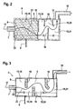
- the FIG. 2 shows a first embodiment of the separation device 4.
- the separation device 4 has a plurality of chambers 15, which are separated from intermediate walls 16 at least partially from each other.
- the intermediate walls 16 protrude in the flow direction (arrow 17) - in particular mutually - from opposite sides into the buffer 5, so that it is subdivided into the chambers 15.
- four chambers 15 are provided, so that a first chamber 18, a second chamber 19, a third chamber 20 and a fourth chamber 21 are present.
- any number of chambers 15 may be provided in the buffer 5.
- the first chamber 18 is completely filled with a porous material.
- the fuel which passes through an inlet 22 into the separation device 4 or the intermediate storage 5, accordingly flows through the porous material arranged in the first chamber 18, in order to reach the downstream chambers 19, 20 and 21.
- the liquid fuel Due to the sponge-like or filter-like formation of the porous material, at least part of the liquid fuel is deposited from the fuel or fuel mixture flowing into the separation device 4 in the latter.
- the liquid fuel is usually in droplet form in the gaseous fuel.
- the drops of liquid fuel now settle on or on the porous material and can be subsequently, for example, due to the influence of gravity, dissipated.
- the thus separated liquid fuel can be temporarily stored in the buffer 5 at least temporarily or be discharged directly from the return line 6 therefrom, preferably in the direction of the fuel tank 2.
- the use of the porous material not only improves the separation effect of the separator 4, but also reduces their pressure loss.
- the intermediate walls 16 are arranged in a flow-through path 23 of the separating device 4 or the intermediate store 5. This means that in each case a deflection of the fuel flowing through the separating device 4 is achieved by the intermediate walls 16. By this deflection, in turn, liquid fuel is separated from the fuel and introduced into the buffer 5. Ideally, any liquid fuel in the fuel is deposited in the separator 4 so that only gaseous fuel is present in the outlet conduit 10.
- FIG. 3 shows a second embodiment of the separation device 4.
- the intermediate walls 16 are again arranged in the flow path 23, so it is in each case a change in direction of the separator 4 flowing through the fuel achieved.
- the intermediate walls 16 consist of the porous material or are coated with this. As it flows through the separation device 4, the fuel therefore comes into contact with the intermediate walls 16 and thus with the porous material. In this way, the separation efficiency of the separation device 4 is significantly increased.
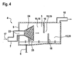
- the FIG. 4 shows a third embodiment of the separation device 4.
- the fuel flowing into the separation device 4 is therefore initially delayed before it enters the first chamber 18.
- the diffuser 24 at least partially comprises the porous material or is at least partially filled with this.
- a drain 25 is provided on the diffuser 24 so that liquid fuel accumulating in the diffuser 24 can escape therefrom and into the intermediate store 5.
- the buffer 5 is divided by means of intermediate walls 16 of the chambers 15, in which case only the first chamber 18, the second chamber 19 and the third chamber 20 are present. Of course, any number of intermediate walls 16 and chambers 15 can also be provided in this embodiment.
- FIGS. 2 and 3 At least the embodiments of FIGS. 2 and 3 is common that the adjacent to the outlet 10 intermediate wall 16 in the direction of the outlet 10th or whose mouth point is curved into the buffer 5.
- the free end of the intermediate wall 16 is displaced in the direction of the outlet line 10, so that insofar as at least a partial cover of the outlet point is given.
- such an embodiment of the intermediate wall 16 and for the third embodiment of FIG. 4 be provided.
Landscapes
- Engineering & Computer Science (AREA)
- Chemical & Material Sciences (AREA)
- Combustion & Propulsion (AREA)
- Mechanical Engineering (AREA)
- General Engineering & Computer Science (AREA)
- Transportation (AREA)
- Chemical Kinetics & Catalysis (AREA)
- Life Sciences & Earth Sciences (AREA)
- Sustainable Development (AREA)
- Sustainable Energy (AREA)
- Cooling, Air Intake And Gas Exhaust, And Fuel Tank Arrangements In Propulsion Units (AREA)
Description
- Die Erfindung betrifft ein Kraftstoffsystem, insbesondere eines Kraftfahrzeugs, mit einem Kraftstofftank und einer Entlüftungseinrichtung zur Entlüftung des Kraftstofftanks, wobei die Entlüftungseinrichtung über zumindest eine einen Zwischenspeicher für flüssigen Kraftstoff aufweisende Abscheidevorrichtung verfügt.
- Kraftstoffsysteme der eingangs genannten Art sind aus dem Stand der Technik bekannt. Sie sind beispielsweise einem Kraftfahrzeug beziehungsweise einem Antriebssystem des Kraftfahrzeugs zugeordnet. Das Antriebssystem verfügt dabei insbesondere über zumindest eine Brennkraftmaschine und ist beispielsweise als Hybridantriebssystem ausgebildet, weist also die Brennkraftmaschine sowie zumindest eine elektrische Maschine auf, wobei die Brennkraftmaschine und die elektrische Maschine ein Antriebsmoment des Antriebssystems zumindest zeitweise gemeinsam erzeugen. Der Brennkraftmaschine wird von dem Kraftstoffsystem Kraftstoff aus dem Kraftstofftank zugeführt. Häufig wird als Kraftstoff ein flüchtiger Kohlenwasserstoffkraftstoff, beispielsweise Benzin, verwendet. Der Kraftstofftank enthält daher normalerweise sowohl ein Volumen an flüssigem Kraftstoff als auch ein Volumen an gasförmigem Kraftstoff, welches insbesondere oberhalb des flüssigen Kraftstoffs anfällt. Der Kraftstofftank kann ein geschlossener Tank, insbesondere ein Drucktank, oder ein teilgeschlossener, insbesondere auch druckloser, Tank sein. Der geschlossene Tank wird insbesondere zur Reduzierung von Emissionen verwendet.
- Bedingt durch Schwankungen der Temperatur des Kraftstoffs, beispielsweise verursacht durch Veränderungen der Umgebungstemperatur, können Druckschwankungen in dem Kraftstofftank auftreten. Aus diesem Grund ist die Entlüftungseinrichtung dem Kraftstofftank zugeordnet. Sie dient der Entlüftung des Kraftstofftanks. Auf diese Weise kann ein zu hoher Druck in dem Kraftstofftank durch die Entlüftungseinrichtung reduziert werden. Zu diesem Zweck entlüftet die Entlüftungseinrichtung den Kraftstofftank beispielsweise durch eine Entlüftungsleitung. Bei dem Entlüften kann durch die Entlüftungseinrichtung beziehungsweise die Entlüftungsleitung sowohl gasförmiger als auch flüssiger Kraftstoff aus dem Kraftstofftank heraus gelangen. Der entlüftete Kraftstoff liegt also zunächst als Gemisch aus gasförmigem und flüssigem Kraftstoff vor. Dies ist insbesondere dann der Fall, wenn das Entlüften des Kraftstofftanks bei hohem Kraftstofftankinnendruck durchgeführt wird. Dabei liegen, bedingt durch den hohen Druck beziehungsweise die große Druckdifferenz zwischen Kraftstofftankinnendruck und dem Druck außerhalb des Kraftstofftanks hohe Strömungsgeschwindigkeiten des entlüfteten Kraftstoffs vor, wodurch flüssiger Kraftstoff von dem gasförmigen Kraftstoff mitgerissen wird.
- Der gasförmige Kraftstoff darf ohne weiteres der Brennkraftmaschine beziehungsweise deren Ansaugsystem zugeführt werden, wobei zwischen dem Kraftstofftank und der Brennkraftmaschine ein der Entlüftungseinrichtung zugeordneter Kraftstoffspeicher, welcher bevorzugt als Aktivkohlespeicher ausgebildet ist, angeordnet sein kann. Der Kraftstoffspeicher dient dazu, gasförmigen Kraftstoff zwischenzuspeichern, also aufzunehmen, wenn nicht benötigter gasförmiger Kraftstoff vorliegt und abzugeben, sobald der gasförmige Kraftstoff in die Brennkraftmaschine abgeführt werden kann. Es darf jedoch kein flüssiger Kraftstoff in den Kraftstoffspeicher beziehungsweise die Brennkraftmaschine gelangen.
- Aus diesem Grund weist die Entlüftungseinrichtung die zumindest eine Abscheidevorrichtung auf, welche zur Trennung von gasförmigem und flüssigem Kraftstoff dient. Die Abscheidevorrichtung ist demnach dazu vorgesehen, das Überführen von flüssigem Kraftstoff von dem Kraftstofftank durch die Entlüftungseinrichtung in die Brennkraftmaschine beziehungsweise den Kraftstoffspeicher zu verhindern. Dabei scheidet die Abscheidevorrichtung flüssigen Kraftstoff ab und lässt gasförmigen Kraftstoff passieren. Der abgeschiedene flüssige Kraftstoff gelangt in den Zwischenspeicher der Abscheidevorrichtung. Der Begriff Zwischenspeicher bedeutet dabei nicht, dass tatsächlich eine (Zwischen-) Speicherung des flüssigen Kraftstoffs vorgesehen ist. Vielmehr kann der flüssige Kraftstoff unmittelbar aus dem Zwischenspeicher beziehungsweise der Abscheidevorrichtung abgeführt werden, bevorzugt in Richtung des Kraftstofftanks. Dabei kann sich jedoch, beispielsweise durch eine Begrenzung des Abführvolumenstroms, insbesondere durch einen Leitungsquerschnitt oder dergleichen, ein Anstieg des Füllstands des Zwischenspeichers ergeben. Der abgeschiedene flüssige Kraftstoff kann demnach zumindest zeitweise nicht so schnell abgeführt werden, wie er in den Zwischenspeicher eingebracht wird. Selbstverständlich ist auch eine Zwischenspeicherung des flüssigen Kraftstoffs, beispielsweise über eine bestimmte Zeitspanne, realisierbar.
- Beim Betreiben des Kraftstoffsystems sollte verhindert werden, dass die sich in dem Zwischenspeicher beziehungsweise der Abscheidevorrichtung befindliche Menge des flüssigen Kraftstoffs eine Grenzmenge überschreitet, der Füllstand des Zwischenspeichers demnach größer als ein Grenzfüllstand wird, weil dies die Wirksamkeit der Abscheidevorrichtung beeinträchtigen kann. Je größer die Menge flüssigen Kraftstoffs in dem Zwischenspeicher ist, umso größer wird das Risiko, dass zusammen mit dem gasförmigen Kraftstoff auch flüssiger Kraftstoff wieder aus der Abscheidevorrichtung heraus gelangt und in Richtung des Kraftstoffspeichers beziehungsweise der Brennkraftmaschine mitgenommen wird. Aus diesem Grund kann der Abscheidevorrichtung die Kraftstofffördereinrichtung zugeordnet werden. Diese wird dazu eingesetzt, flüssigen Kraftstoff aus dem Zwischenspeicher zu fördern, insbesondere in Richtung des Kraftstofftanks. Die Kraftstofffördereinrichtung ist dabei üblicherweise als Saugstrahlpumpe ausgebildet, wobei als Betriebsmittel der Saugstrahlpumpe häufig Kraftstoff verwendet wird, welcher von einer Kraftstoffpumpe des Kraftstoffsystems aus dem Kraftstofftank in Richtung der Brennkraftmaschine gefördert wird. Insbesondere wenn ein großer Volumenstrom an flüssigem Kraftstoff in die Entlüftungseinrichtung beziehungsweise die Abscheidevorrichtung gelangt, kann es jedoch bei aus dem Stand der Technik bekannten Kraftstoffsystemen vorkommen, dass zumindest ein Teil des flüssigen Kraftstoffs zusammen mit dem gasförmigen Kraftstoff auch wieder aus der Abscheidevorrichtung heraus gelangt.
- Aus dem Stand der Technik ist beispielsweise die gattungsbildende
WO 2006/041400 A1 bekannt. Diese zeigt eine Belüftungseinrichtung für einen Kraftstofftank. Die Belüftungseinrichtung verfügt über einen Behälter, mittels welchem Kraftstoff aufgefangen wird, welcher über Ventile abgeführt wird. In dem Behälter sind Querwände vorgesehen, die von unterschiedlichen Seiten des Behälters ausgehen, sodass sie miteinander überlappen. Als Alternative wird der Einsatz von Stahlwolle oder dünnen Filtern zur Tropfenabscheidung gekannt. - Es ist nun Aufgabe der Erfindung, ein Kraftstoffsystem vorzuschlagen, weiche über eine Abscheidevorrichtung mit verbesserter Abscheidewirkung, insbesondere auch bei einem erhöhten Volumenstrom an flüssigem Kraftstoff, verfügt.
- Dies wird erfindungsgemäß erreicht, indem die Abscheidevorrichtung zumindest bereichsweise aus einem porösen Material besteht und/oder mit diesem gefüllt ist. Das poröse Material ist dabei vorzugsweise derart in der Abscheidevorrichtung angeordnet, dass es von dem in die Abscheidevorrichtung eingebrachten Kraftstoff, insbesondere dem flüssigen Kraftstoff, durchströmt oder zumindest angeströmt wird. Unter dem porösen Material ist dabei ein Material zu verstehen, welches eine Vielzahl von Ausnehmungen aufweist beziehungsweise einschließt, welche zumindest teilweise miteinander in Strömungsverbindung stehen können. Die Ausnehmungen können jedoch alternativ auch strömungstechnisch vollständig voneinander getrennt vorliegen. Das poröse Material weist dabei eine Filterwirkung auf, welche den flüssigen Kraftstoff zurückhält oder zumindest verzögert, also seine Strömungsgeschwindigkeit verringert, während der gasförmige Kraftstoff das poröse Material im Wesentlichen ungehindert oder lediglich mit geringfügiger Verzögerung passieren kann. Der flüssige Kraftstoff bleibt entweder an dem porösen Material selbst hängen oder wird aufgrund der reduzierten Strömungsgeschwindigkeit aus dem strömenden Kraftstoff abgeschieden. In letzterem Fall sinkt der flüssige Kraftstoff insbesondere aufgrund von Schwerkrafteinfluss nach unten und setzt sich in dem Zwischenspeicher ab. Der an dem porösen Material oder in dem Zwischenspeicher anfallende flüssige Kraftstoff kann anschließend abgeführt werden, beispielbeispielsweise in Richtung des Kraftstofftanks. Mittels des porösen Materials kann die Abscheidewirkung der Abscheidevorrichtung deutlich verbessert werden. Zudem wird der Druckverlust der Abscheidevorrichtung verringert. Das poröse Material ist dabei vorzugsweise dauerbeständig gegenüber dem Kraftstoff.
- Zudem ist vorgesehen, dass die Abscheidevorrichtung mehrere Kammern aufweist, welche von zumindest einer Zwischenwandung zumindest bereichsweise voneinander abgetrennt sind. Vorzugsweise liegen die Kammern in dem Zwischenspeicher vor, so dass dieser in die Kammern unterteilt ist. Die Abtrennung der Kammern voneinander liegt lediglich in räumlicher Hinsicht, nicht notwendigerweise jedoch in strömungstechnischer Hinsicht vor. Es kann also durchaus vorgesehen sein, dass die Kammern zwar in räumlicher Hinsicht vollständig mittels der Zwischenwandung voneinander abgetrennt sind, diese jedoch aus einem kraftstoffdurchlässigen Material besteht, beziehungsweise dazu ausgebildet ist, den Kraftstoff passieren zu lassen. Auf diese Weise stehen jeweils zumindest zwei der Kammern miteinander in Strömungsverbindung. Alternativ oder zusätzlich kann es auch vorgesehen sein, dass die Kammern mittels der Zwischenwandung in räumlicher Hinsicht lediglich bereichsweise voneinander abgetrennt sind. In diesem Fall kann der Kraftstoff um die Zwischenwandung herum strömen und so von einer der Kammern in eine andere beziehungsweise umgekehrt gelangen. Die Kammern können gleich groß sein, also dasselbe Volumen aufweisen, oder mit unterschiedlicher Größe ausgebildet sein. Beispielsweise kann die Kammer, welche einem Einlass der Abscheidevorrichtung zugeordnet ist, größer sein als eine benachbart zu der ersten Kammer angeordnete Kammer.
- Die Erfindung sieht vor, dass die Zwischenwandung in einem Durchströmungsweg der Abscheidevorrichtung angeordnet ist. Der Durchströmungsweg der Abscheidevorrichtung ist derjenige Weg, auf welchem der Kraftstoff die Abscheidevorrichtung durchströmt beziehungsweise ohne die Zwischenwandung durchströmen würde. Die Zwischenwandung soll also derart in der Abscheidevorrichtung angeordnet sein, dass der die Abscheidevorrichtung durchströmende Kraftstoff von der Zwischenwandung umgelenkt wird und dabei auf sie aufprallt, bevorzugt senkrecht. Auf diese Weise bleiben Tropfen des flüssigen Kraftstoffs an der Zwischenwand hängen, so dass sich auf der Zwischenwandung ein Tropfenfilm bildet. Dieser Tropfenfilm nimmt nachfolgend weiteren flüssigen Kraftstoff, welcher in dem die Abscheidevorrichtung durchströmenden Kraftstoff enthalten ist, auf. Der gasförmige Kraftstoff wird hingegen von der Zwischenwandung lediglich umgelenkt und durchströmt die Abscheidevorrichtung weiter. Der Tropfenfilm wird, vorzugsweise durch Schwerkrafteinfluss, abgeführt, insbesondere in Richtung des Zwischenspeichers, in welchem der flüssige Kraftstoff aufgefangen wird.
- Die Erfindung sieht zudem vor, dass die Zwischenwandung zumindest bereichsweise, insbesondere vollständig, aus dem porösen Material besteht und/oder vorzugsweise mit diesem wenigstens teilweise beschichtet ist. Mittels des porösen Materials kann die Filterwirkung der Abscheidevorrichtung beziehungsweise der Zwischenwandung weiter erhöht werden. Insbesondere wenn die Zwischenwandung zumindest bereichsweise aus dem porösen Material besteht, kann zudem der Strömungswiderstand gegenüber dem die Abscheidevorrichtung durchströmenden Kraftstoff verringert werden. Auf diese Weise wird ein geringerer Druckverlust der Abscheidevorrichtung erzielt und somit der Energiebedarf des Kraftstoffsystems verringert. Dabei besteht die Zwischenwandung vorzugsweise in Richtung ihrer kleinsten Abmessungen und/oder in Richtung des Durchströmungswegs vollständig aus dem porösen Material. Zusätzlich oder alternativ kann die Zwischenwandung eine zumindest teilweise Beschichtung aus dem porösen Material aufweisen. In diesem Fall besteht die Zwischenwandung aus einem Kern aus einem beliebigen Material, beispielsweise einem Kunststoff, auf welches das poröse Material aufgebracht ist. Es kann auch vorgesehen sein, dass die Beschichtung aus dem porösen Material derart an dem Kern angeordnet ist, dass ein Abströmweg für den flüssigen Kraftstoff zwischen dem porösen Material und dem Kern vorliegt, durch welchen an der Zwischenwandung abgeschiedener flüssiger Kraftstoff abgeführt wird. Dies ist insbesondere vorteilhaft, wenn die Ausnehmungen des porösen Materials Strömungskanäle sind, welche in Richtung des Durchströmungswegs vorliegen, mithin also senkrecht zu dem Abströmweg und dem Kern der Zwischenwandung vorliegen.
- Die Erfindung sieht alternative vor, dass wenigstens ein Teilraum des Zwischenspeichers und/oder mindestens eine der Kammern, wenigstens bereichsweise mit dem porösen Material gefüllt ist. Insbesondere wenn nicht erfindungsgemäß die Abscheidevorrichtung nicht in Kammern aufgeteilt ist, liegt das poröse Material zumindest in dem Teilraum des Zwischenspeichers vor. Der Zwischenspeicher wird dabei zum Abscheiden des flüssigen Kraftstoffs aus dem in die Ablagevorrichtung eingebrachten Kraftstoff von Letzterem durchströmt. Zusätzlich oder alternativ kann wenigstens eine der Kammern mit dem porösen Material gefüllt sein. Das bedeutet, dass mittels des porösen Materials aus dem den Zwischenspeicher beziehungsweise die eine der Kammern durchströmenden Kraftstoff flüssiger Kraftstoff wirkungsvoll ausgeschieden wird.
- Eine Weiterbildung der Erfindung sieht vor, dass ein in den Zwischenspeicher mündender Einlass der Abscheidevorrichtung einen Diffusor mit sich in Richtung des Zwischenspeichers vergrößerndem Querschnitt aufweist. Der Querschnitt vergrößert sich in Strömungsrichtung, der in die Abscheidevorrichtung eingebrachte Kraftstoff wird also in dem Diffusor bedingt durch den sich vergrößerndem Querschnitt verzögert. Vorzugsweise weist der Diffusor dabei einen kreisförmigen Querschnitt auf. Bedingt durch die verringerte Geschwindigkeit, mit welcher der Kraftstoff in die Abscheidevorrichtung gelangt, wird dessen Querschnitt effektiver zum Abscheiden des flüssigen Kraftstoffs ausgenutzt. Insbesondere kann auf diese Weise auch eine Verringerung des Strömungswiderstand und damit des Druckverlusts des Kraftstoffs beim Durchströmen der Abscheidevorrichtung erzielt werden. Zusätzlich verringert die verringerte Geschwindigkeit die Gefahr, dass gasförmiger Kraftstoff flüssigen Kraftstoff nach dessen Abscheiden wieder mitreißt.
- Eine Weiterbildung der Erfindung sieht vor, dass der Diffusor zumindest bereichsweise das poröse Material aufweist und/oder wenigstens teilweise mit diesem gefüllt ist. Somit kann bereits in dem Diffusor flüssiger Kraftstoff aus dem Kraftstoff mit hoher Abscheidewirkung abgeschieden werden. Der Diffusor kann dabei derart ausgebildet sein, dass in dem Diffusor abgeschiedener flüssiger Kraftstoff unmittelbar in den Zwischenspeicher gelangt.
- Eine Weiterbildung der Erfindung sieht vor, dass das poröse Material schwammartig oder filterartig, insbesondere ein Vlies, ist. Unter schwammartig ist dabei zu verstehen, dass das Material eine Vielzahl von zueinander versetzt angeordneten Hohlräumen aufweist, welche zumindest teilweise miteinander in Strömungsverbindung stehen. Ist das poröse Material filterartig, so ist es von mehreren Strömungskanälen durchsetzt, welche nicht miteinander in Strömungsverbindung stehen. Der Kraftstoff kann dabei durch die Strömungskanäle von einer Seite des porösen Materials auf die andere strömen, wobei bedingt durch den Querschnitt der Strömungskanäle das poröse Material als Sieb wirkt. Dabei kann der flüssige Kraftstoff das poröse Material schlechter durchströmen als der gasförmige Kraftstoff. Beispielsweise ist das poröse Material ein Vlies, also ein textiles Flächengebilde aus einzelnen, ungeordneten Fasern. Alternativ kann das poröse Material selbstverständlich auch als Gewebe, Gestrick oder Gewirke beziehungsweise als Membran vorliegen.
- Eine Weiterbildung der Erfindung sieht mindestens ein der Abscheidevorrichtung strömungstechnisch vorgeschaltetes oder nachgeschaltetes Entlüftungsventil zur Entlüftung des Kraftstofftanks durch die Abscheidevorrichtung vor. Das Entlüftungsventil ist dabei der Entlüftungseinrichtung zugeordnet. Das Entlüftungsventil kann derart eingestellt werden, dass es zur Entlüftung des Kraftstofftanks öffnet oder zur Unterbrechung der Entlüftung schließt. Es liegt beispielsweise als FTIV (Fuel Tank Isolation Valve) vor. Das Entlüftungsventil kann als Taktventil ausgebildet sein, welches ein Einstellen von diskreten Schaltzuständen (geöffnet und geschlossen) erlaubt. Besonders bevorzugt ist das Entlüftungsventil als Stetigventil ausgelegt, welches nicht lediglich die diskreten Schaltzustände zulässt, sondern ein Einstellen des Durchströmungsquerschnitts in mehreren Stufen, besonders bevorzugt ein stetiges Einstellen, ermöglicht. Auf diese Weise ist der Volumenstrom durch die Abscheidevorrichtung, insbesondere stetig, gesteuert und/oder geregelt einstellbar. Das Entlüftungsventil ist der Abscheidevorrichtung strömungstechnisch vorgeschaltet oder nachgeschaltet, der Kraftstoff muss demnach für ein Durchströmen der Abscheidevorrichtung stets auch das Entlüftungsventil passieren. Das Entlüftungsventil kann mit der Abscheidevorrichtung oder der Kraftstofffördereinrichtung integriert sein. Das Entlüftungsventil kann also modular in die Kraftstofffördereinrichtung integriert vorliegen.
- Eine Weiterbildung der Erfindung sieht vor, dass der Abscheidevorrichtung zumindest ein in Abhängigkeit des Kraftstofftankfüllstands schaltendes Belüftungsventil und/oder zumindest ein dem Kraftstofftank zugeordnetes Sicherheitsventil strömungstechnisch vorgeschaltet sind. Das Belüftungsventil ist insbesondere als FLVV (Fill Limit Venting Valve) ausgebildet. Ein solches ermöglicht ein Belüften des Kraftstofftanks, solange der Kraftstofftankfüllstand kleiner ist als ein bestimmter Kraftstofftankfüllstand, insbesondere Kraftstofftankmaximalfüllstand. Über das Belüftungsventil wird somit das Belüften des Kraftstofftanks, insbesondere bei einem Zuführen von Kraftstoff in den Kraftstofftank, sichergestellt. Zusätzlich oder alternativ kann das Sicherheitsventil vorgesehen sein, welches beispielsweise als Überroll-Sicherheitsventil beziehungsweise ROV (Roll Over Valve) ausgebildet ist. Sowohl das Belüftungsventil als auch das Sicherheitsventil sind üblicherweise dem Kraftstofftank zugeordnet und der Abscheidevorrichtung strömungstechnisch vorgeschaltet, so dass der Kraftstoff zunächst das Belüftungsventil beziehungsweise das Sicherheitsventil durchläuft, bevor es in die Abscheidevorrichtung gelangt.
- Die Erfindung betrifft auch ein Antriebssystem mit einem Kraftstoffsystem gemäß den vorstehenden Ausführungen. Das Antriebssystem verfügt dabei insbesondere über zumindest eine Brennkraftmaschine und ist beispielsweise als Hybridantriebssystem ausgebildet.
- Die Erfindung wird nachfolgend anhand der in der Zeichnung dargestellten Ausführungsbeispiele näher erläutert, ohne dass eine Beschränkung der Erfindung erfolgt. Dabei zeigen:
- Figur 1
- eine schematische Darstellung eines Kraftstoffsystems mit einer Abscheidevorrichtung,
- Figur 2
- die Abscheidevorrichtung in einer ersten Ausführungsform,
- Figur 3
- die Abscheidevorrichtung in einer zweiten Ausführungsform, und
- Figur 4
- die Abscheidevorrichtung in einer dritten Ausführungsform.
- Die
Figur 1 zeigt eine schematische Darstellung eines Kraftstoffsystems 1. Das Kraftstoffsystem 1 ist beispielsweise Bestandteil eines Kraftfahrzeugs beziehungsweise eines Antriebssystems des Kraftfahrzeugs. Das Kraftstoffsystem 1 verfügt über einen Kraftstofftank 2 und eine Entlüftungseinrichtung 3 zur Entlüftung des Kraftstofftanks 1. Die Entlüftungseinrichtung 3 weist eine Abscheidevorrichtung 4 mit einem Zwischenspeicher 5 auf. Die Abscheidevorrichtung 4 dient dazu, flüssigen Kraftstoff aus einem Gemisch von flüssigem und gasförmigem Kraftstoff abzuscheiden. Der abgeschiedene flüssige Kraftstoff liegt anschließend in dem Zwischenspeicher 5 vor und kann, beispielsweise durch eine Rückführungsleitung 6, wieder dem Kraftstofftank 2 zugeführt werden. Die Rückführungsleitung 6 weist bevorzugt ein Ventil, insbesondere Drainageventil beziehungsweise Rückschlagventil, auf. Anstelle der Rückführungsleitung 6 kann auch lediglich das Ventil vorgesehen sein, insbesondere wenn die Abscheidevorrichtung 4 zumindest bereichsweise in dem Kraftstofftank 2 vorliegt, so dass durch das Ventil aus dem Zwischenspeicher 5 austretender Kraftstoff unmittelbar in den Kraftstofftank gelangt. Das Ventil ist derart ausgebildet, dass Kraftstoff durch die Rückführungsleitung 6 lediglich aus dem Zwischenspeicher 5 herausgelangen, nicht jedoch in ihn hineingelangen kann. Somit wird verhindert, dass durch die Rückführungsleitung 6 Kraftstoff aus dem Kraftstofftank 2 in den Zwischenspeicher 5 gelangt. - Die Entlüftungseinrichtung 3 steht über eine Entlüftungsleitung 7 in Strömungsverbindung mit dem Kraftstofftank 2. Auf der dem Kraftstofftank 2 zugewandten Seite der Entlüftungsleitung 7 beziehungsweise in dem Kraftstofftank 2 ist dabei ein Belüftungsventil 8 vorgesehen, welches in Abhängigkeit des Kraftstofftankfüllstands schaltet. Üblicherweise ist das Belüftungsventil 8 derart ausgeführt, dass es nur bei einem Kraftstofftankfüllstand unterhalb eines bestimmten Kraftstofftankfüllstands, insbesondere eines Maximalkraftstofftankfüllstands, geöffnet ist, also Kraftstoff, insbesondere gasförmiger Kraftstoff, aus dem Kraftstofftank in die Entlüftungsleitung 7 gelangen kann. Die Entlüftungsleitung 7 mündet in den Zwischenspeicher 5 der Abscheidevorrichtung 4 ein, bevorzugt durch eine Seitenwand 9 oder einen Boden des Zwischenspeichers 5. Beabstandet von der Entlüftungsleitung 7 beziehungsweise deren Mündungsstelle in den Zwischenspeicher 5 mündet eine Auslassleitung 10 in den Zwischenspeicher 5 ein, bevorzugt durch eine Decke 11 des Zwischenspeichers 5. Die Mündungsstelle der Auslassleitung 10 in den Zwischenspeicher 5 ist damit bevorzugt derart angeordnet, dass lediglich gasförmiger Kraftstoff aus dem Zwischenspeicher 5 in die Auslassleitung 10 gelangen kann. Dazu sind die Mündungsstellen von Auslassleitung 10 und Entlüftungsleitung 7 bevorzugt an gegenüberliegenden Seiten des Zwischenspeichers 5 angeordnet. Die Auslassleitung 10 weist ein Entlüftungsventil 12 auf, welches mittels einer Betätigungseinrichtung 13 betätigbar ist. Das Entlüftungsventil 12 und die Betätigungseinrichtung 13 sind dabei bevorzugt derart ausgebildet, dass der Durchströmungsquerschnitt des Entlüftungsventils 12 stetig einstellbar ist. Auf der der Abscheidevorrichtung 4 abgewandten Seite mündet die Auslassleitung 10 in einen Kraftstoffspeicher 14, insbesondere einen Aktivkohlespeicher, ein. Der Kraftstoffspeicher 14 dient der Zwischenspeicherung von gasförmigem Kraftstoff.
- Die Abscheidevorrichtung 4 ist üblicherweise zumindest bereichsweise, insbesondere vollständig, in dem Kraftstofftank 2, angeordnet. Auch eine Anordnung außerhalb des Kraftstofftanks 2 ist jedoch möglich. Alternativ kann die Abscheidevorrichtung 4 auch in eine Leitung, beispielsweise die Entlüftungsleitung 7, integriert sein. In einer bevorzugten Ausführungsform ist die Abscheidevorrichtung derart ausgebildet, dass sie beziehungsweise die Entlüftungseinrichtung 3 einen bestimmten Druckverlust aufweist. Dieser ist dabei derart gewählt, dass bei einem Entlüften der Kraftstofftanks 2 mittels der Entlüftungseinrichtung 3 ein eventuell vorhandenes Ventil, beispielsweise das Belüftungsventil 8, nicht in dessen Geschlossenstellung gebracht wird. Das Belüftungsventil 8 weist üblicherweise einen Schwimmer auf, welcher einen Ventilsitz des Belüftungsventils 8 freigibt, solange der Kraftstofftankfüllstand kleiner als ein bestimmter Kraftstofftankfüllstand ist. Wird der mittels der Entlüftungseinrichtung 3, also durch das Belüftungsventil 8, abgeführte Volumenstrom größer als ein Auslegungsvolumenstrom, so kann der Schwimmer von dem Volumenstrom beziehungsweise dem entlüfteten Kraftstoff in den Ventilsitz, also in die Geschlossenstellung verlagert werden, so dass ein weiteres Entlüften des Kraftstofftanks 2 nicht möglich ist. Dies gilt insbesondere bei vollständig geöffnetem Entlüftungsventil 12.
- Üblicherweise wird der Druckverlust der Entlüftungseinrichtung 3 durch Anpassen des Entlüftungsventils 12 eingestellt, beispielsweise durch Einbringen eines Drosselelements. Hier soll es nun bevorzugt vorgesehen sein, dass der Druckverlust der Entlüftungseinrichtung 3 durch Anpassen der Abscheidevorrichtung 4 beziehungsweise deren Druckverlust erfolgt, beispielsweise durch Vorsehen eines angepassten Drosselelements. Das Entlüftungsventil 12 weist demnach bevorzugt kein Drosselelement auf. Das Drosselelement kann jedoch selbstverständlich zusätzlich vorgesehen sein.
- Die
Figur 2 zeigt eine erste Ausführungsform der Abscheidevorrichtung 4. Die Abscheidevorrichtung 4 weist mehrere Kammern 15 auf, welche von Zwischenwandungen 16 zumindest bereichsweise voneinander abgetrennt sind. Die Zwischenwandungen 16 ragen dabei in Strömungsrichtung (Pfeil 17) - insbesondere wechselseitig - von sich gegenüberliegenden Seiten in den Zwischenspeicher 5 hinein, so dass dieser in die Kammern 15 unterteilt ist. In dem vorliegenden Fall sind vier Kammern 15 vorgesehen, so dass eine erste Kammer 18, eine zweite Kammer 19, eine dritte Kammer 20 und eine vierte Kammer 21 vorliegen. Prinzipiell kann jedoch eine beliebige Anzahl an Kammern 15 in dem Zwischenspeicher 5 vorgesehen sein. In der hier dargestellten Ausführungsform ist die erste Kammer 18 vollständig mit einem porösen Material gefüllt. Der Kraftstoff, welcher durch einen Einlass 22 in die Abscheidevorrichtung 4 beziehungsweise den Zwischenspeicher 5 gelangt, durchströmt demnach das in der ersten Kammer 18 angeordnete poröse Material, um in die in Strömungsrichtung nachfolgenden Kammern 19, 20 und 21 zu gelangen. - Bedingt durch die schwammartige oder filterartige Ausbildung des porösen Materials, wird in diesem zumindest ein Teil des flüssigen Kraftstoffs aus dem in die Abscheidevorrichtung 4 einströmenden Kraftstoff beziehungsweise Kraftstoffgemisch abgeschieden. Der flüssige Kraftstoff liegt üblicherweise in Tropfenform in dem gasförmigen Kraftstoff vor. Die Tropfen aus flüssigem Kraftstoff setzen sich nun auf beziehungsweise an dem porösen Material ab und können nachfolgen, beispielsweise aufgrund von Schwerkrafteinfluss, abgeführt werden. Der somit abgeschiedene flüssige Kraftstoff kann in dem Zwischenspeicher 5 zumindest zeitweise zwischengespeichert werden oder unmittelbar durch die Rückführungsleitung 6 aus diesem ausgebracht werden, vorzugsweise in Richtung des Kraftstofftanks 2. Die Verwendung des porösen Materials verbessert nicht nur die Abscheidewirkung der Abscheidevorrichtung 4, sondern verringert auch deren Druckverlust.
- Die Zwischenwandungen 16 sind in einem Durchströmungsweg 23 der Abscheidevorrichtung 4 beziehungsweise des Zwischenspeichers 5 angeordnet. Das bedeutet, dass durch die Zwischenwandungen 16 jeweils eine Umlenkung des die Abscheidevorrichtung 4 durchströmenden Kraftstoffs erzielt wird. Durch dieses Umlenken wird wiederum flüssiger Kraftstoff aus dem Kraftstoff abgeschieden und in den Zwischenspeicher 5 eingebracht. Idealerweise wird in der Abscheidevorrichtung 4 jeglicher in dem Kraftstoff befindliche flüssige Kraftstoff abgeschieden, so dass in der Auslassleitung 10 lediglich gasförmiger Kraftstoff vorliegt.
- Die
Figur 3 zeigt eine zweite Ausführungsform der Abscheidevorrichtung 4. Bei dieser Ausführungsform sind die Zwischenwandungen 16 wieder in dem Durchströmungsweg 23 angeordnet, es wird also jeweils eine Richtungsänderung des die Abscheidevorrichtung 4 durchströmenden Kraftstoffs erzielt. Die Zwischenwandungen 16 bestehen dabei aus dem porösen Material beziehungsweise sind mit diesem beschichtet. Beim Durchströmen der Abscheidevorrichtung 4 gerät der Kraftstoff demnach in Kontakt mit den Zwischenwandungen 16 und damit mit dem porösen Material. Auf diese Weise wird die Abscheidewirkung der Abscheidevorrichtung 4 deutlich erhöht. - Die
Figur 4 zeigt eine dritte Ausführungsform der Abscheidevorrichtung 4. Bei dieser weist der Einlass 22 einen Diffusor 24 auf, wobei sich der Querschnitt des Diffusors 24 in Richtung des Zwischenspeichers 5 vergrößert. Der in die Abscheidevorrichtung 4 einströmende Kraftstoff wird demnach zunächst verzögert, bevor er in die erste Kammer 18 eintritt. Dabei kann es vorgesehen sein, dass der Diffusor 24 zumindest bereichsweise das poröse Material aufweist beziehungsweise wenigstens teilweise mit diesem gefüllt ist. Besonders bevorzugt ist ein Ablauf 25 an dem Diffusor 24 vorgesehen, so dass in dem Diffusor 24 anfallender flüssiger Kraftstoff aus diesem heraus und in den Zwischenspeicher 5 gelangen kann. Auch in der hier dargestellten Ausführungsform ist der Zwischenspeicher 5 mittels Zwischenwandungen 16 den Kammern 15 unterteilt, wobei hier lediglich die erste Kammer 18, die zweite Kammer 19 und die dritte Kammer 20 vorliegen. Selbstverständlich können auch bei dieser Ausführungsform eine beliebige Anzahl Zwischenwandungen 16 und Kammern 15 vorgesehen sein. - Zumindest den Ausführungsformen der
Figuren 2 und 3 ist gemeinsam, dass die zu der Auslassleitung 10 benachbarte Zwischenwandung 16 in Richtung der Auslassleitung 10 beziehungsweise deren Mündungsstelle in den Zwischenspeicher 5 gekrümmt ist. Das freie Ende der Zwischenwandung 16 ist dabei in Richtung der Auslassleitung 10 verlagert, so dass insoweit eine zumindest teilweise Abdeckung der Mündungsstelle gegeben ist. Selbstredend kann eine solche Ausführung der Zwischenwandung 16 auch für die dritte Ausführungsform derFigur 4 vorgesehen sein. -
- 1
- Kraftstoffsystem
- 2
- Kraftstofftank
- 3
- Entlüftungseinrichtung
- 4
- Abscheidevorrichtung
- 5
- Zwischenspeicher
- 6
- Rückführungsleitung
- 7
- Entlüftungsleitung
- 8
- Belüftungsventil
- 9
- Seitenwand
- 10
- Auslassleitung
- 11
- Decke
- 12
- Entlüftungsventil
- 13
- Betätigungseinrichtung
- 14
- Kraftstoffspeicher
- 15
- Kammer
- 16
- Zwischenwandung
- 17
- Pfeil
- 18
- Erste Kammer
- 19
- Zweite Kammer
- 20
- Dritte Kammer
- 21
- Vierte Kammer
- 22
- Einlass
- 23
- Durchströmungsweg
- 24
- Diffusor
- 25
- Ablauf
Claims (9)
- Kraftstoffsystem (1), insbesondere eines Kraftfahrzeugs, mit einem Kraftstofftank (2) und einer Entlüftungseinrichtung (3) zur Entlüftung des Kraftstofftanks (2), wobei die Entlüftungseinrichtung (3) über zumindest eine einen Zwischenspeicher (5) für flüssigen Kraftstoff aufweisende Abscheidevorrichtung (4) verfügt, wobei die Abscheidevorrichtung (4) mehrere Kammern (15,18,19,20,21) aufweist, welche von zumindest einer Zwischenwandung (16) zumindest bereichsweise voneinander abgetrennt sind, wobei der die Abscheidevorrichtung (4) durchströmende Kraftstoff von der zumindest einen Zwischenwandung (16) umgelenkt wird, so dass Tropfen des flüssigen Kraftstoffs an ihr hängenbleiben, dadurch gekennzeichnet, dass die Abscheidevorrichtung (4) zumindest bereichsweise aus einem porösen Material besteht und/oder mit diesem gefüllt ist.
- Kraftstoffsystem nach Anspruch 1, dadurch gekennzeichnet, dass die Zwischenwandung (16) in einem Durchströmungsweg (23) der Abscheidevorrichtung (4) angeordnet ist.
- Kraftstoffsystem nach einem der vorhergehenden Ansprüche, dadurch gekennzeichnet, dass die Zwischenwandung (16) zumindest bereichsweise, insbesondere vollständig, aus dem porösen Material besteht und/oder mit diesem wenigstens teilweise beschichtet ist.
- Kraftstoffsystem nach einem der vorhergehenden Ansprüche, dadurch gekennzeichnet, dass wenigstens ein Teilraum des Zwischenspeichers (5) und/oder mindestens eine der Kammern (15,18,19,20,21) wenigstens bereichsweise mit dem porösen Material gefüllt ist.
- Kraftstoffsystem nach einem der vorhergehenden Ansprüche, dadurch gekennzeichnet, dass ein in den Zwischenspeicher (5) mündender Einlass (23) der Abscheidevorrichtung (4) einen Diffusor (24) mit sich in Richtung des Zwischenspeichers (5) vergrößerndem Querschnitt aufweist.
- Kraftstoffsystem nach einem der vorhergehenden Ansprüche, dadurch gekennzeichnet, dass der Diffusor (24) zumindest bereichsweise das poröse Material aufweist und/oder wenigstens teilweise mit diesem gefüllt ist.
- Kraftstoffsystem nach einem der vorhergehenden Ansprüche, dadurch gekennzeichnet, dass das poröse Material schwammartig oder filterartig, insbesondere ein Vlies, ist.
- Kraftstoffsystem nach einem der vorhergehenden Ansprüche, gekennzeichnet durch mindestens ein der Abscheidevorrichtung (4) strömungstechnisch vorgeschaltetes oder nachgeschaltetes Entlüftungsventil (12) zur Entlüftung des Kraftstofftanks (2) durch die Abscheidevorrichtung (4).
- Kraftstoffsystem nach einem der vorhergehenden Ansprüche, dadurch gekennzeichnet, dass der Abscheidevorrichtung (4) zumindest ein in Abhängigkeit des Kraftstofftankfüllstands schaltendes Belüftungsventil (8) und/oder zumindest ein dem Kraftstofftank zugeordnetes Sicherheitsventil strömungstechnisch vorgeschaltet sind.
Applications Claiming Priority (1)
| Application Number | Priority Date | Filing Date | Title |
|---|---|---|---|
| DE102010055320A DE102010055320A1 (de) | 2010-12-21 | 2010-12-21 | Kraftstoffsystem |
Publications (2)
| Publication Number | Publication Date |
|---|---|
| EP2468558A1 EP2468558A1 (de) | 2012-06-27 |
| EP2468558B1 true EP2468558B1 (de) | 2013-07-24 |
Family
ID=45421771
Family Applications (1)
| Application Number | Title | Priority Date | Filing Date |
|---|---|---|---|
| EP11009834.0A Not-in-force EP2468558B1 (de) | 2010-12-21 | 2011-12-14 | Kraftstoffsystem |
Country Status (5)
| Country | Link |
|---|---|
| US (1) | US9752544B2 (de) |
| EP (1) | EP2468558B1 (de) |
| CN (1) | CN102562389B (de) |
| DE (1) | DE102010055320A1 (de) |
| ES (1) | ES2425546T3 (de) |
Families Citing this family (13)
| Publication number | Priority date | Publication date | Assignee | Title |
|---|---|---|---|---|
| US8950382B2 (en) * | 2004-12-16 | 2015-02-10 | Raval A.C.S. Ltd. | Vehicle fuel system and components thereof |
| US20110303197A1 (en) * | 2010-06-09 | 2011-12-15 | Honda Motor Co., Ltd. | Microcondenser device |
| DE102011106008B4 (de) | 2011-06-30 | 2018-10-31 | Audi Ag | Verfahren zum Betreiben eines Kraftstoffsystems sowie Kraftstoffsystem |
| DE102011106006B4 (de) | 2011-06-30 | 2019-05-16 | Audi Ag | Verfahren zum Betreiben eines Kraftstoffsystems sowie Kraftstoffsystem |
| EP2927039B1 (de) * | 2014-04-01 | 2020-06-10 | Plastic Omnium Advanced Innovation and Research | Fahrzeugvorratssystem und Konverter zur Verwendung in einem solchen System |
| DE102014007694B4 (de) * | 2014-05-23 | 2024-01-11 | Audi Ag | Verfahren zur Absaugung von flüssigem Kraftstoff aus einer zur Abscheidung des flüssigen Kraftstoffs dienenden Flüssigkeitsfalle in einem Kraftstofftank eines Kraftfahrzeugs, sowie Kraftstoffanlage für ein Kraftfahrzeug |
| DE102015012656B4 (de) | 2014-10-22 | 2025-07-17 | Audi Ag | Verfahren zum Betreiben einer Kraftstoffanlage für ein Kraftfahrzeug sowie entsprechende Kraftstoffanlage |
| DE102015005754A1 (de) | 2015-05-05 | 2016-11-10 | Audi Ag | Magnetventileinrichtung für ein Kraftfahrzeug |
| DE102015010354B4 (de) | 2015-08-06 | 2017-03-16 | Audi Ag | Betriebsmitteltankanordnung für ein Kraftfahrzeug |
| DE102015011406A1 (de) | 2015-08-29 | 2017-03-16 | Audi Ag | Kraftstoffabscheider für einen Kraftstofftank |
| DE102015217763B4 (de) * | 2015-09-16 | 2021-02-25 | Röchling Automotive SE & Co. KG | Tank für Lagerung und Lieferung von Flüssigkeiten mit an der Tankwandung angeordneten Funktionskomponenten |
| CN112590535A (zh) * | 2020-12-24 | 2021-04-02 | 天津天银汽车科技有限公司 | 一种汽车燃油箱 |
| CN119122716A (zh) * | 2024-08-09 | 2024-12-13 | 中国第一汽车股份有限公司 | 车辆的供油系统以及车辆 |
Family Cites Families (38)
| Publication number | Priority date | Publication date | Assignee | Title |
|---|---|---|---|---|
| US1654577A (en) * | 1922-05-18 | 1928-01-03 | Collins Process Inc | Conversion apparatus for refining hydrocarbon materials |
| US1654578A (en) * | 1922-05-23 | 1928-01-03 | Collins Process Inc | Expansion process and apparatus for refining hydrocarbon materials |
| US2025059A (en) * | 1934-07-07 | 1935-12-24 | Buffalo Foundry & Machine Co | Evaporator |
| NL87758C (de) * | 1954-06-30 | |||
| US2868324A (en) * | 1955-12-05 | 1959-01-13 | Robert J Anderson | Vent line centrifuge |
| DE1251233B (de) * | 1965-01-14 | |||
| US3326230A (en) * | 1965-10-18 | 1967-06-20 | Rca Corp | Valve discriminating means |
| US3556734A (en) * | 1968-02-05 | 1971-01-19 | Leander J Peterson | Exhaust gas conditioning apparatus |
| US3942499A (en) * | 1973-07-26 | 1976-03-09 | I. Jordan Kunik | Carburetor improvement system and apparatus |
| FR2262609A1 (en) | 1974-03-01 | 1975-09-26 | Peugeot & Renault | Petrol tank breathing device - has membrane valve controlling gas flow to petrol removing device |
| JPS59165854A (ja) * | 1983-03-09 | 1984-09-19 | Aisan Ind Co Ltd | 燃料蒸発損失防止装置 |
| US4717401A (en) * | 1986-09-24 | 1988-01-05 | Casco Products Corporation | Fuel vapor recovery system |
| US4960153A (en) * | 1989-11-03 | 1990-10-02 | G. T. Products, Inc. | Fuel tank vapor vent valve |
| JP3158698B2 (ja) * | 1992-08-28 | 2001-04-23 | トヨタ自動車株式会社 | 蒸発燃料排出抑止装置 |
| DE4312374A1 (de) | 1993-04-17 | 1994-10-20 | Daimler Benz Ag | Be- und Entlüftungseinrichtung eines Fahrzeug-Kraftstofftanks |
| US5355861A (en) * | 1993-12-07 | 1994-10-18 | Kyosan Denki Co., Ltd. | Evaporative emission control system |
| US5716522A (en) * | 1996-10-25 | 1998-02-10 | Kuss Corporation | Non-woven depth media in-tank fuel filter |
| US5850821A (en) * | 1997-04-28 | 1998-12-22 | Ford Global Technologies, Inc. | Method and system for estimating air/fuel ratio of an engine having a non-heated fuel vaporizer |
| FR2774951B1 (fr) | 1998-02-19 | 2000-05-05 | Plastic Omnium Cie | Reservoir a carburant muni d'un systeme d'evacuation des gaz |
| AT3803U1 (de) | 1999-09-01 | 2000-08-25 | Steyr Daimler Puch Ag | Schwimmerventil für die kraftstofftankanlage eines kraftfahrzeuges |
| DE10007522B4 (de) | 2000-02-18 | 2006-10-26 | Siemens Ag | Verfahren zur Trennung von Kraftstoffdampf-Luft-Gemischen und Vorrichtung zur Durchführung dieses Verfahrens |
| JP3659482B2 (ja) * | 2000-06-08 | 2005-06-15 | 日産自動車株式会社 | 燃料蒸気処理装置 |
| KR100392408B1 (ko) * | 2000-10-05 | 2003-07-22 | 학교법인 서강대학교 | 미세다공성 제올라이트 또는 유사 물질로 된 거대다공성발포체 및 스폰지 구조의 고분자 주형을 이용하는 이의제조 방법 |
| DE10063414A1 (de) * | 2000-12-19 | 2002-06-27 | Kautex Textron Gmbh & Co Kg | Kraftstoffbehälter |
| DE10120542B4 (de) * | 2001-04-26 | 2004-07-15 | Kautex Textron Gmbh & Co. Kg | Kraftstoffbehälter |
| US6769415B2 (en) | 2001-05-25 | 2004-08-03 | General Motors Corporation | Evaporative control system |
| ITTO20020906A1 (it) * | 2002-10-17 | 2004-04-18 | Dayco Fuel Man Spa | Accumulatore temporaneo di vapori di carburante per un autoveicolo. |
| US6807952B1 (en) * | 2003-07-22 | 2004-10-26 | Ti Group Automotive Systems, L.L.C. | Fuel tank and fuel flow control device |
| US20050045160A1 (en) | 2003-09-03 | 2005-03-03 | Alicia Peterson | Evaporative emissions canister with incorporated liquid fuel trap |
| US6895943B1 (en) | 2003-11-12 | 2005-05-24 | Daimlerchrysler Corporation | Fuel vent assembly with floatless rollover protection |
| US20050235968A1 (en) * | 2004-04-26 | 2005-10-27 | Pachciarz Mahlon R | Fuel vapor recovery system |
| SE0402504L (sv) * | 2004-10-15 | 2006-02-28 | Scania Cv Abp | Avluftningsanordning för bränsletankar, användning av en sådan anordning samt ett motorfordon försett med en sådan anordning |
| US7225798B2 (en) * | 2005-05-31 | 2007-06-05 | Sentec E&E Co., Ltd. | Device combing fuel control valve and carbon canister, or fuel tank |
| US7870848B2 (en) | 2008-02-01 | 2011-01-18 | Ford Global Technologies, Llc | Reducing fuel-vapor emissions by vortex effect |
| US8777051B2 (en) | 2008-04-02 | 2014-07-15 | Brunswick Corporation | Fuel venting systems having protective membranes |
| US20100126477A1 (en) | 2008-11-21 | 2010-05-27 | Gm Global Technology Operations, Inc. | Evaporative emissions control system |
| EP2241746A1 (de) * | 2009-04-14 | 2010-10-20 | Continental Automotive GmbH | Kupplungsvorrichtung |
| JP5378180B2 (ja) * | 2009-12-02 | 2013-12-25 | 愛三工業株式会社 | 分離膜モジュールとこれを備える蒸発燃料処理装置 |
-
2010
- 2010-12-21 DE DE102010055320A patent/DE102010055320A1/de not_active Ceased
-
2011
- 2011-12-14 EP EP11009834.0A patent/EP2468558B1/de not_active Not-in-force
- 2011-12-14 ES ES11009834T patent/ES2425546T3/es active Active
- 2011-12-16 US US13/328,339 patent/US9752544B2/en not_active Expired - Fee Related
- 2011-12-21 CN CN201110432467.XA patent/CN102562389B/zh not_active Expired - Fee Related
Also Published As
| Publication number | Publication date |
|---|---|
| ES2425546T3 (es) | 2013-10-16 |
| CN102562389A (zh) | 2012-07-11 |
| CN102562389B (zh) | 2016-06-22 |
| EP2468558A1 (de) | 2012-06-27 |
| DE102010055320A1 (de) | 2012-06-21 |
| US9752544B2 (en) | 2017-09-05 |
| US20120160218A1 (en) | 2012-06-28 |
Similar Documents
| Publication | Publication Date | Title |
|---|---|---|
| EP2468558B1 (de) | Kraftstoffsystem | |
| EP1924335B1 (de) | Einrichtung zur trennung eines gas-flüssigkeitsgemisches | |
| DE202010001191U1 (de) | Ventil zur Steuerung eines Gasstromes, Flüssigkeitsabscheider, Entlüftungssystem sowie Verbrennungsmotor mit einem derartigen Ventil | |
| DE202008001586U1 (de) | Flüssigkeits-Dampfabscheider | |
| DE102009018000B4 (de) | Abscheider zum Abscheiden von Flüssigkeitströpfchen aus einem Aerosol | |
| EP2579958B1 (de) | Filtereinrichtung, insbesondere flüssigkeitsfilter | |
| DE102008026734A1 (de) | Pumpeinrichtung zur Förderung von Kraftstoff in einem Kraftstoffbehälter | |
| DE102017125065A1 (de) | Ölnebelabscheider | |
| DE102011119868A1 (de) | Filtervorrichtung | |
| DE202007007120U1 (de) | Kraftstoffzuführeinrichtung, insbesondere für eine Brennkraftmaschine | |
| DE102012021309A1 (de) | Kurbelgehäuseentlüftungsvorrichtung | |
| DE112011100225T5 (de) | Abflussrohr für Gas-Flüssigkeits-Abscheidesysteme | |
| DE102004036083B4 (de) | Ansaugvorrichtung | |
| EP1094204B1 (de) | Entlüftungsvorrichtung mit Ölabscheider für ein Kurbelgehäuse einer Brennkraftmaschine | |
| WO2016041728A1 (de) | Wasserabscheider mit durch schwimmerventil gesichertem wasserüberlauf | |
| EP2468560B1 (de) | Kraftstoffsystem | |
| WO2015052166A1 (de) | Einfüllstutzen für einen kraftfahrzeug-betriebsflüssigkeitsbehälter | |
| EP2468557B1 (de) | Kraftstoffsystem | |
| DE60306482T2 (de) | Verarbeitungsvorrichtung für Kraftstoffdämpfe | |
| DE102017120139A1 (de) | Ölnebelabscheider mit Druckbegrenzungsventilen | |
| DE102012022762A1 (de) | Kraftstoffbereitstellungssystem für ein Fahrzeug mit Brennkraftmaschine | |
| AT3803U1 (de) | Schwimmerventil für die kraftstofftankanlage eines kraftfahrzeuges | |
| DE102015111247A1 (de) | Öltröpfchen-Abscheidevorrichtung, insbesondere für ein Verbrennungsmotor-Antriebsaggregat | |
| DE102012022551A1 (de) | Zyklonabscheider zur Abscheidung von Öltröpfchen aus Kurbelwellengehäusegasen eines Verbrennungsmotors | |
| DE102018208316A1 (de) | Ansaugkammer für eine Betriebsmittelpumpe, Betriebsmittelpumpe sowie Betriebsmittelbehälter |
Legal Events
| Date | Code | Title | Description |
|---|---|---|---|
| AK | Designated contracting states |
Kind code of ref document: A1 Designated state(s): AL AT BE BG CH CY CZ DE DK EE ES FI FR GB GR HR HU IE IS IT LI LT LU LV MC MK MT NL NO PL PT RO RS SE SI SK SM TR |
|
| AX | Request for extension of the european patent |
Extension state: BA ME |
|
| PUAI | Public reference made under article 153(3) epc to a published international application that has entered the european phase |
Free format text: ORIGINAL CODE: 0009012 |
|
| 17P | Request for examination filed |
Effective date: 20130102 |
|
| REG | Reference to a national code |
Ref country code: DE Ref legal event code: R079 Ref document number: 502011001071 Country of ref document: DE Free format text: PREVIOUS MAIN CLASS: B60K0015035000 Ipc: B60K0037040000 |
|
| GRAP | Despatch of communication of intention to grant a patent |
Free format text: ORIGINAL CODE: EPIDOSNIGR1 |
|
| RIC1 | Information provided on ipc code assigned before grant |
Ipc: B60K 37/04 20060101AFI20130227BHEP |
|
| INTG | Intention to grant announced |
Effective date: 20130328 |
|
| GRAS | Grant fee paid |
Free format text: ORIGINAL CODE: EPIDOSNIGR3 |
|
| GRAA | (expected) grant |
Free format text: ORIGINAL CODE: 0009210 |
|
| AK | Designated contracting states |
Kind code of ref document: B1 Designated state(s): AL AT BE BG CH CY CZ DE DK EE ES FI FR GB GR HR HU IE IS IT LI LT LU LV MC MK MT NL NO PL PT RO RS SE SI SK SM TR |
|
| REG | Reference to a national code |
Ref country code: GB Ref legal event code: FG4D Free format text: NOT ENGLISH |
|
| REG | Reference to a national code |
Ref country code: CH Ref legal event code: EP |
|
| REG | Reference to a national code |
Ref country code: AT Ref legal event code: REF Ref document number: 623201 Country of ref document: AT Kind code of ref document: T Effective date: 20130815 |
|
| REG | Reference to a national code |
Ref country code: IE Ref legal event code: FG4D Free format text: LANGUAGE OF EP DOCUMENT: GERMAN |
|
| REG | Reference to a national code |
Ref country code: DE Ref legal event code: R096 Ref document number: 502011001071 Country of ref document: DE Effective date: 20130919 |
|
| REG | Reference to a national code |
Ref country code: ES Ref legal event code: FG2A Ref document number: 2425546 Country of ref document: ES Kind code of ref document: T3 Effective date: 20131016 |
|
| REG | Reference to a national code |
Ref country code: NL Ref legal event code: VDEP Effective date: 20130724 |
|
| REG | Reference to a national code |
Ref country code: LT Ref legal event code: MG4D |
|
| PG25 | Lapsed in a contracting state [announced via postgrant information from national office to epo] |
Ref country code: LT Free format text: LAPSE BECAUSE OF FAILURE TO SUBMIT A TRANSLATION OF THE DESCRIPTION OR TO PAY THE FEE WITHIN THE PRESCRIBED TIME-LIMIT Effective date: 20130724 Ref country code: HR Free format text: LAPSE BECAUSE OF FAILURE TO SUBMIT A TRANSLATION OF THE DESCRIPTION OR TO PAY THE FEE WITHIN THE PRESCRIBED TIME-LIMIT Effective date: 20130724 Ref country code: NO Free format text: LAPSE BECAUSE OF FAILURE TO SUBMIT A TRANSLATION OF THE DESCRIPTION OR TO PAY THE FEE WITHIN THE PRESCRIBED TIME-LIMIT Effective date: 20131024 Ref country code: IS Free format text: LAPSE BECAUSE OF FAILURE TO SUBMIT A TRANSLATION OF THE DESCRIPTION OR TO PAY THE FEE WITHIN THE PRESCRIBED TIME-LIMIT Effective date: 20131124 Ref country code: PT Free format text: LAPSE BECAUSE OF FAILURE TO SUBMIT A TRANSLATION OF THE DESCRIPTION OR TO PAY THE FEE WITHIN THE PRESCRIBED TIME-LIMIT Effective date: 20131125 Ref country code: SE Free format text: LAPSE BECAUSE OF FAILURE TO SUBMIT A TRANSLATION OF THE DESCRIPTION OR TO PAY THE FEE WITHIN THE PRESCRIBED TIME-LIMIT Effective date: 20130724 Ref country code: CY Free format text: LAPSE BECAUSE OF FAILURE TO SUBMIT A TRANSLATION OF THE DESCRIPTION OR TO PAY THE FEE WITHIN THE PRESCRIBED TIME-LIMIT Effective date: 20130828 |
|
| PG25 | Lapsed in a contracting state [announced via postgrant information from national office to epo] |
Ref country code: FI Free format text: LAPSE BECAUSE OF FAILURE TO SUBMIT A TRANSLATION OF THE DESCRIPTION OR TO PAY THE FEE WITHIN THE PRESCRIBED TIME-LIMIT Effective date: 20130724 Ref country code: SI Free format text: LAPSE BECAUSE OF FAILURE TO SUBMIT A TRANSLATION OF THE DESCRIPTION OR TO PAY THE FEE WITHIN THE PRESCRIBED TIME-LIMIT Effective date: 20130724 Ref country code: NL Free format text: LAPSE BECAUSE OF FAILURE TO SUBMIT A TRANSLATION OF THE DESCRIPTION OR TO PAY THE FEE WITHIN THE PRESCRIBED TIME-LIMIT Effective date: 20130724 Ref country code: PL Free format text: LAPSE BECAUSE OF FAILURE TO SUBMIT A TRANSLATION OF THE DESCRIPTION OR TO PAY THE FEE WITHIN THE PRESCRIBED TIME-LIMIT Effective date: 20130724 Ref country code: LV Free format text: LAPSE BECAUSE OF FAILURE TO SUBMIT A TRANSLATION OF THE DESCRIPTION OR TO PAY THE FEE WITHIN THE PRESCRIBED TIME-LIMIT Effective date: 20130724 Ref country code: GR Free format text: LAPSE BECAUSE OF FAILURE TO SUBMIT A TRANSLATION OF THE DESCRIPTION OR TO PAY THE FEE WITHIN THE PRESCRIBED TIME-LIMIT Effective date: 20131025 |
|
| PG25 | Lapsed in a contracting state [announced via postgrant information from national office to epo] |
Ref country code: CY Free format text: LAPSE BECAUSE OF FAILURE TO SUBMIT A TRANSLATION OF THE DESCRIPTION OR TO PAY THE FEE WITHIN THE PRESCRIBED TIME-LIMIT Effective date: 20130724 |
|
| PG25 | Lapsed in a contracting state [announced via postgrant information from national office to epo] |
Ref country code: SK Free format text: LAPSE BECAUSE OF FAILURE TO SUBMIT A TRANSLATION OF THE DESCRIPTION OR TO PAY THE FEE WITHIN THE PRESCRIBED TIME-LIMIT Effective date: 20130724 Ref country code: CZ Free format text: LAPSE BECAUSE OF FAILURE TO SUBMIT A TRANSLATION OF THE DESCRIPTION OR TO PAY THE FEE WITHIN THE PRESCRIBED TIME-LIMIT Effective date: 20130724 Ref country code: RO Free format text: LAPSE BECAUSE OF FAILURE TO SUBMIT A TRANSLATION OF THE DESCRIPTION OR TO PAY THE FEE WITHIN THE PRESCRIBED TIME-LIMIT Effective date: 20130724 Ref country code: EE Free format text: LAPSE BECAUSE OF FAILURE TO SUBMIT A TRANSLATION OF THE DESCRIPTION OR TO PAY THE FEE WITHIN THE PRESCRIBED TIME-LIMIT Effective date: 20130724 Ref country code: DK Free format text: LAPSE BECAUSE OF FAILURE TO SUBMIT A TRANSLATION OF THE DESCRIPTION OR TO PAY THE FEE WITHIN THE PRESCRIBED TIME-LIMIT Effective date: 20130724 |
|
| PLBE | No opposition filed within time limit |
Free format text: ORIGINAL CODE: 0009261 |
|
| STAA | Information on the status of an ep patent application or granted ep patent |
Free format text: STATUS: NO OPPOSITION FILED WITHIN TIME LIMIT |
|
| BERE | Be: lapsed |
Owner name: AUDI A.G. Effective date: 20131231 |
|
| 26N | No opposition filed |
Effective date: 20140425 |
|
| REG | Reference to a national code |
Ref country code: DE Ref legal event code: R097 Ref document number: 502011001071 Country of ref document: DE Effective date: 20140425 |
|
| PG25 | Lapsed in a contracting state [announced via postgrant information from national office to epo] |
Ref country code: LU Free format text: LAPSE BECAUSE OF FAILURE TO SUBMIT A TRANSLATION OF THE DESCRIPTION OR TO PAY THE FEE WITHIN THE PRESCRIBED TIME-LIMIT Effective date: 20131214 |
|
| REG | Reference to a national code |
Ref country code: IE Ref legal event code: MM4A |
|
| PG25 | Lapsed in a contracting state [announced via postgrant information from national office to epo] |
Ref country code: BE Free format text: LAPSE BECAUSE OF NON-PAYMENT OF DUE FEES Effective date: 20131231 Ref country code: IE Free format text: LAPSE BECAUSE OF NON-PAYMENT OF DUE FEES Effective date: 20131214 |
|
| PG25 | Lapsed in a contracting state [announced via postgrant information from national office to epo] |
Ref country code: MC Free format text: LAPSE BECAUSE OF FAILURE TO SUBMIT A TRANSLATION OF THE DESCRIPTION OR TO PAY THE FEE WITHIN THE PRESCRIBED TIME-LIMIT Effective date: 20130724 |
|
| PG25 | Lapsed in a contracting state [announced via postgrant information from national office to epo] |
Ref country code: SM Free format text: LAPSE BECAUSE OF FAILURE TO SUBMIT A TRANSLATION OF THE DESCRIPTION OR TO PAY THE FEE WITHIN THE PRESCRIBED TIME-LIMIT Effective date: 20130724 |
|
| PG25 | Lapsed in a contracting state [announced via postgrant information from national office to epo] |
Ref country code: TR Free format text: LAPSE BECAUSE OF FAILURE TO SUBMIT A TRANSLATION OF THE DESCRIPTION OR TO PAY THE FEE WITHIN THE PRESCRIBED TIME-LIMIT Effective date: 20130724 |
|
| PG25 | Lapsed in a contracting state [announced via postgrant information from national office to epo] |
Ref country code: BG Free format text: LAPSE BECAUSE OF FAILURE TO SUBMIT A TRANSLATION OF THE DESCRIPTION OR TO PAY THE FEE WITHIN THE PRESCRIBED TIME-LIMIT Effective date: 20130724 Ref country code: HU Free format text: LAPSE BECAUSE OF FAILURE TO SUBMIT A TRANSLATION OF THE DESCRIPTION OR TO PAY THE FEE WITHIN THE PRESCRIBED TIME-LIMIT; INVALID AB INITIO Effective date: 20111214 Ref country code: RS Free format text: LAPSE BECAUSE OF FAILURE TO SUBMIT A TRANSLATION OF THE DESCRIPTION OR TO PAY THE FEE WITHIN THE PRESCRIBED TIME-LIMIT Effective date: 20131024 Ref country code: MK Free format text: LAPSE BECAUSE OF FAILURE TO SUBMIT A TRANSLATION OF THE DESCRIPTION OR TO PAY THE FEE WITHIN THE PRESCRIBED TIME-LIMIT Effective date: 20130724 |
|
| REG | Reference to a national code |
Ref country code: CH Ref legal event code: PL |
|
| PG25 | Lapsed in a contracting state [announced via postgrant information from national office to epo] |
Ref country code: MT Free format text: LAPSE BECAUSE OF FAILURE TO SUBMIT A TRANSLATION OF THE DESCRIPTION OR TO PAY THE FEE WITHIN THE PRESCRIBED TIME-LIMIT Effective date: 20130724 |
|
| PG25 | Lapsed in a contracting state [announced via postgrant information from national office to epo] |
Ref country code: LI Free format text: LAPSE BECAUSE OF NON-PAYMENT OF DUE FEES Effective date: 20141231 Ref country code: CH Free format text: LAPSE BECAUSE OF NON-PAYMENT OF DUE FEES Effective date: 20141231 |
|
| REG | Reference to a national code |
Ref country code: FR Ref legal event code: PLFP Year of fee payment: 5 |
|
| REG | Reference to a national code |
Ref country code: FR Ref legal event code: PLFP Year of fee payment: 6 |
|
| PGFP | Annual fee paid to national office [announced via postgrant information from national office to epo] |
Ref country code: GB Payment date: 20161222 Year of fee payment: 6 |
|
| PGFP | Annual fee paid to national office [announced via postgrant information from national office to epo] |
Ref country code: FR Payment date: 20161222 Year of fee payment: 6 Ref country code: ES Payment date: 20161221 Year of fee payment: 6 |
|
| PGFP | Annual fee paid to national office [announced via postgrant information from national office to epo] |
Ref country code: IT Payment date: 20161230 Year of fee payment: 6 |
|
| REG | Reference to a national code |
Ref country code: AT Ref legal event code: MM01 Ref document number: 623201 Country of ref document: AT Kind code of ref document: T Effective date: 20161214 |
|
| PG25 | Lapsed in a contracting state [announced via postgrant information from national office to epo] |
Ref country code: AT Free format text: LAPSE BECAUSE OF NON-PAYMENT OF DUE FEES Effective date: 20161214 |
|
| GBPC | Gb: european patent ceased through non-payment of renewal fee |
Effective date: 20171214 |
|
| REG | Reference to a national code |
Ref country code: FR Ref legal event code: ST Effective date: 20180831 |
|
| PG25 | Lapsed in a contracting state [announced via postgrant information from national office to epo] |
Ref country code: FR Free format text: LAPSE BECAUSE OF NON-PAYMENT OF DUE FEES Effective date: 20180102 Ref country code: IT Free format text: LAPSE BECAUSE OF NON-PAYMENT OF DUE FEES Effective date: 20171214 Ref country code: AL Free format text: LAPSE BECAUSE OF FAILURE TO SUBMIT A TRANSLATION OF THE DESCRIPTION OR TO PAY THE FEE WITHIN THE PRESCRIBED TIME-LIMIT Effective date: 20130724 |
|
| PG25 | Lapsed in a contracting state [announced via postgrant information from national office to epo] |
Ref country code: GB Free format text: LAPSE BECAUSE OF NON-PAYMENT OF DUE FEES Effective date: 20171214 |
|
| REG | Reference to a national code |
Ref country code: ES Ref legal event code: FD2A Effective date: 20190703 |
|
| PG25 | Lapsed in a contracting state [announced via postgrant information from national office to epo] |
Ref country code: ES Free format text: LAPSE BECAUSE OF NON-PAYMENT OF DUE FEES Effective date: 20171215 |
|
| PGFP | Annual fee paid to national office [announced via postgrant information from national office to epo] |
Ref country code: DE Payment date: 20201231 Year of fee payment: 10 |
|
| REG | Reference to a national code |
Ref country code: DE Ref legal event code: R119 Ref document number: 502011001071 Country of ref document: DE |
|
| PG25 | Lapsed in a contracting state [announced via postgrant information from national office to epo] |
Ref country code: DE Free format text: LAPSE BECAUSE OF NON-PAYMENT OF DUE FEES Effective date: 20220701 |