EP2468965A2 - Elément de fixation multifonction doté d'un élément de connexion coudé - Google Patents
Elément de fixation multifonction doté d'un élément de connexion coudé Download PDFInfo
- Publication number
- EP2468965A2 EP2468965A2 EP11189568A EP11189568A EP2468965A2 EP 2468965 A2 EP2468965 A2 EP 2468965A2 EP 11189568 A EP11189568 A EP 11189568A EP 11189568 A EP11189568 A EP 11189568A EP 2468965 A2 EP2468965 A2 EP 2468965A2
- Authority
- EP
- European Patent Office
- Prior art keywords
- mounting
- recess
- multipurpose
- fixing
- mounting piece
- Prior art date
- Legal status (The legal status is an assumption and is not a legal conclusion. Google has not performed a legal analysis and makes no representation as to the accuracy of the status listed.)
- Granted
Links
Images


Classifications
-
- E—FIXED CONSTRUCTIONS
- E03—WATER SUPPLY; SEWERAGE
- E03C—DOMESTIC PLUMBING INSTALLATIONS FOR FRESH WATER OR WASTE WATER; SINKS
- E03C1/00—Domestic plumbing installations for fresh water or waste water; Sinks
- E03C1/02—Plumbing installations for fresh water
- E03C1/021—Devices for positioning or connecting of water supply lines
-
- E—FIXED CONSTRUCTIONS
- E03—WATER SUPPLY; SEWERAGE
- E03C—DOMESTIC PLUMBING INSTALLATIONS FOR FRESH WATER OR WASTE WATER; SINKS
- E03C1/00—Domestic plumbing installations for fresh water or waste water; Sinks
- E03C1/02—Plumbing installations for fresh water
- E03C2001/028—Alignment aids for plumbing installations
Definitions
- the invention relates to a multipurpose fastener with a line connection angle.
- Line connection angles also called battery connection angles
- a connection angle can be fixed to a wall in order to deflect a conduit extending essentially parallel to the wall in one direction by, for example, 90 °.
- the line connection angle is connected to one or more fittings to the pipe connection as well as a fixing element, to fix the connection bracket either on the wall directly or on a mounting rail. While a direct attachment to the wall for a connection angle is sufficient, the mounting rail is mainly used for attaching multiple battery connection angle.
- FIG. 13 shows a schematic overview of the known solutions.
- the object of the invention is therefore to provide a more flexible attachment for battery connections, in particular battery connection angle.
- a sheet-like terminal body which has at least two openings or fixing holes for fixing the element to a wall.
- the line angle in particular a battery connection angle, a wall angle, or another fluid-carrying medium is attached.
- the holes in the flat connection body are suitably designed to be freely accessible.
- At least one fixing device is arranged on the rear side of the connection body.
- the fixing device is designed such that it has a corresponding fixing element as a counterpart to a mounting piece, so that the connector body is secured against rotation and preferably in at least two positions, such that at least one of the attachment through holes of the connector body of an opening on the mounting piece for mounting the connector body on Mounting piece opposite.
- the fixing device comprises at least one recess on the connection body.
- a locking pin is additionally provided as a counterpart, which is fitted in the recess.
- This counterpart can be fixed to the mounting piece, but also present as an additional element.
- the counterpart allowed a torsion-proof coupling of the connector body with the mounting piece.
- the multi-purpose fastening element according to the invention can be fastened directly to a wall or a plaster element by means of a plurality of screws via the at least two fastening holes provided in the connector body.
- existing mounting pieces such as mounting rails or mounting elements
- these include a part of the fixing device such that the connector body can be coupled with its rear side with the mounting piece. Consequently, two different embodiments are suitable, either for mounting on a mounting rail or directly on the wall no longer necessary. Rather, the multi-purpose fastening element according to the invention can be used for both types of fastening.
- the fixing device on the back of the connector body comprises an asymmetrically shaped recess.
- the counterpart, for example, a securing or positioning bolt is also designed asymmetrically in this embodiment, such that at least two different positions of the bolt are provided within the recess on the back of the connector body.
- the connector body can be flanged in different positions on the mounting piece.
- the positions are configured in such a way that when the connecting body is flanged over the positioning bolt to the mounting piece, at least one of the two fastening through holes faces a correspondingly arranged opening in the mounting piece, so that the connecting body is firmly but simultaneously reversibly fixed via an additional connection to the mounting piece.
- the opening at the Mounting piece can have an internal thread for this purpose.
- the connection may be a screw but also a stuck bolt or connector.
- the asymmetrical configuration of the fixing device causes a rotationally secure connection of the connecting body to the mounting piece. This allows a total of a quick and easy attachment of the connector body to the mounting piece, even without a fitter must know an exact position of the fixing device and its elements.
- the fixing device is designed with two adjacent recesses in the connection body.
- bolts are used, which are present either as a movable and separable element or attached to the mounting piece in an alternative embodiment.
- a plurality of recesses are provided as fixing elements in the connection body and two fixing bolts.
- a first fixing element in the form of a recess with a first diameter and a second fixing element in the form of a recess with a second diameter is provided.
- the different diameters allow a more precise positioning or a clear assignment of possible fixing bolts on the mounting piece.
- the recesses can be different deep. This way you can Installer quickly find the correct position of the connector body with respect to the mounting piece during assembly and turn the body to the desired position via a rotation.
- the fixing device comprises two securing or fixing bolts of different lengths. This allows an installer to couple the connector by means of the longer fixing bolt with the mounting piece and then to achieve an anti-rotation in the desired position by coupling with the second bolt.
- a plurality of recesses may be provided in the connection body for the second fixing bolt or a plurality of recesses in the mounting piece for the second fixing bolt. This allows by means of the first fastening bolt a coupling between the connecting body and mounting piece and a positioning of the fastening element and thus the line angle in different positions on the second fixing bolt.
- the fixing bolts or the securing elements may be made of a material which is softer than the material of the mounting piece or the material of the connection body.
- the fixation and complete attachment of the connector body to the mounting piece via a connection through one of the openings of the connector body is reversible. Due to the different positioning of the connector body on the mounting piece a plurality of openings are necessary either on the connector body or on the mounting piece, of which at least one opposite each other in a rotationally secure positioning of the connector body on the mounting piece.
- the fixing bolts or securing elements can be equipped with barbs or retaining clips or retaining elements, so that after a rotation-proof positioning of the connector body on the mounting piece, a first, if only rudimentary fastening and mounting is achieved. In this way, the assembly is simplified, as an unintentional "falling off of the connector is avoided., Of course, can also fixation or locking pins use.
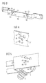
- FIG. 1 shows a flexible fastener according to the proposed principle.
- the flexible fastener is suitable Both for attachment directly to the wall and on an additionally provided mounting piece.
- the fastening element comprises a flat connection body 4, whose rear side faces the viewer.
- a battery connection angle comprising the two connections 2 and 3 is mounted on the opposite front side.
- a pipe is flanged, for example, runs parallel along the wall.
- the connection 3 in turn serves for fastening a pipe, which leads away substantially perpendicularly to the wall, a pipe or another element which can guide a fluid medium.
- the flat connection body 4 has three spaced-apart openings 40, 41 and 44, the connecting line forms an isosceles triangle substantially.
- the openings are designed as fastening through-holes 40, 41 and 44 and are easily accessible from the front side of the connection body 4.
- screws can be inserted through the fastening through-holes and screwed into dowels in the wall. Through the openings a three-point fixing of the connection body and thus of the fastening element with the battery connection angle is possible.
- a fixing device for fixing to a mounting rail, however, a fixing device is additionally provided.
- this comprises two recesses 42 and 43, which are arranged substantially vertically below the opening 41.
- one of the recesses also lies on the connecting line between the two fastening holes 40 and 44.
- the diameter of the two recesses 42 and 43 is less than that of the mounting holes 40, 41 and 44.
- the recesses are relatively flat and in particular only depressions, but not continuous holes in the flat connection body 4. They can be round, square or even have other cross sections.
- the recesses may include various shapes, so that assembly can only take place in predetermined positions.
- FIG. 2 shows the further processing of the flexible fastener. While the recesses 42 and 43 remain substantially free for attachment to the wall, securing pins 46 and 47 are now inserted into the recesses for attachment to a mounting body.
- the locking pins themselves may be available separately. In the present case they are recessed in the recesses in the connection body, but they can also be attached to a mounting rail, so that the connection body can be easily attached.
- FIG. 3 now shows a mounting rail on which the flexible fastener can be flanged and fastened.
- the mounting rail suitable in the illustrated embodiment for the attachment of two elements or battery connection angles, this includes a plurality of holes 53, 54, 55, 56 and 57 at the two different positions 51. These are at the mounting piece in the yoke between the two legs each left and arranged to the right of the center of the yoke of the mounting rail. Their distance from the shortened legs or to the respective other region is chosen so that after a flanging of the individual fastening elements, on the one hand, they do not obstruct one another, but on the other hand do not protrude beyond the U-shaped area.
- Rail can also be used any other shaped rail.
- FIG. 4 shows an enlarged view of the region 51 to illustrate the function of the individual holes 53 to 57.
- the openings 53 and 54 correspond to the mounting holes 41, 40 and 44 of the flat terminal body 4th
- the fixing holes 55, 56 and 57 have a smaller diameter substantially equal to the diameter of the locking pins 46 and 47 of FIG. 2 equivalent.
- the distances between the holes 55 and 56 to each other or the holes 55 and 57 to each other are selected so that they substantially correspond to the distance of the locking pins 46 and 47.
- the large hole 53 is located on a line passing through the small fixing holes 55 and 57, the hole 54 on a line, which is predetermined by the small fixing holes 55 and 56.
- the arrangement of the large holes and the small holes to each other different Anflanschpositionen the flat connector body with its locking pins on the mounting piece are possible.
- the position of the large holes 53 and 54 corresponds to the position of the mounting hole 41 in the different positions.
- the flat connector body can be flanged over the two locking pin in a first step to the mounting piece, in which the locking pin are sunk in the desired position corresponding to small holes.
- a screw or other fastening element for example a pin or a bolt through the mounting hole 41 and the opposite hole 53 or 54 are inserted and fixed.
- the large holes 53 and 54 optionally have a correspondingly designed internal thread.
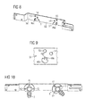
- connection body 5 shows a representation of the flexible fastener in the flanged state on a mounting piece.
- the position of the connection body and thus also the position of the battery connection angle 2 and 3 has been selected such that it extends substantially 45 ° to an axis spanned by the longitudinal leg of the mounting piece.
- the two locking pins 46 and 47 are inserted into the fixing holes 55 and 57, so that the opening 53 is directly above the mounting hole 41.
- the opening 56 and the opening 54 are free and covered on the back by the surface of the connection body 4.
- FIG. 6 Another mounting position of the battery connection angle with the flat terminal body 4 shows the FIG. 6 ,
- the locking pin 46 and 47 are flanged into the fixing holes 55 and 57 of the right position of the mounting piece.
- the holes 56 and 54 are covered in the mounting piece by the connector body 4, while in the hole 53, a fastener is introduced, for example, with its internal thread a screw is screwed for fixing and final attachment of the connector body and the battery connection angle.
- the connector 4 in the two FIG. 5 and 6 shown positions and rotated by 90 °, respectively.
- the fasteners such as screws or pins inserted for final installation and optionally with the internal thread in the mounting holes 53 and 54 connected.
- connection body In an alternative embodiment, however, it is also possible to effect a different positioning of the connection body and thus of the battery connection angle via a configuration and a corresponding positioning of the recesses in the connection body itself.
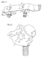
- FIG. 12 shows a related embodiment.
- the terminal body as a T- or cross-shaped element in contrast to the konchoiden shape of Figures 1 and 2 designed for the purpose of additional material savings.
- a first recess 42b of a fixing element 42a is provided along the connecting line of the fastening holes 40 and 44.
- This has a diameter which is greater than that of the mounting holes 40, 41 and 44 and serves to receive a corresponding fixing or securing pin.
- the recesses 42c, 42d and 42e are arranged with a significantly smaller diameter by 45 ° rotationally symmetrical.
- the recesses 42c to 42e extend along an imaginary circular line around the center of the recess 42b. They of the fixing element serve to position fixing the connection body 4 on a mounting rail.
- the mounting rail also includes the locking pins for connecting the connector body.
- a first securing pin of the fastening element is designed on the mounting rail with a diameter which substantially corresponds to the diameter of the recess 42b. This pin is also made slightly longer than the positioning safety pin to achieve a first positioning by the installer during assembly easy.
- the locking pin on the mounting rail which engages in one of the recesses 42c, 42d and 42e of the fixing element, is arranged in one direction at the corresponding distance.
- three additional mounting holes are made on the mounting rail, which have the same angle with respect to a center of the main securing pin with the large diameter of 45 ° to each other. They thus essentially correspond to alignment of the recesses 42c, 42d and 42e on the connector body.
- a different positioning of the connector with respect to the mounting piece can be achieved by an embodiment of the various recesses of the fixing device on the back of the connector body. If the securing pin for the recesses 42b protrudes a little longer than the positioning pin for one of the recesses 42c, 42d and 42e, a particularly simple assembly is possible. So a fitter can position the connection body on the locking pin with the large diameter in a particularly simple manner and then set the final position of the terminal body by a rotational movement about the center of the recess 42b.
- a further embodiment of the flexible fastening element according to the invention shows the FIG. 7 ,
- the fixing element is realized by an asymmetric recess, for example in the form of an inverted mushroom, boat or anchor.
- the recess 48 is formed to receive a corresponding separately available or integrated on the mounting piece counterpart 60.
- the counterpart 60 forms the locking pin of the fixing element for connection to a mounting piece.
- a suitably suitable mounting piece from the front shows the FIG. 8 , Also realized here are two different positions of the connecting piece and thus the battery connection angle.
- the mounting piece 50 includes on its U-shaped leg each two groups of holes with the elements 46 a, 53 and 54. The distance between the legs and the respective regions 51 along the yoke is selected so that flanged with battery terminal angle and connector body this do not interfere with each other. Depending on the length of the yoke, additional regions may also be provided.
- FIG. 9 shows an enlarged view of a region 51.
- the holes 53 and 54 are equipped and form the mounting holes for a subsequent final fixation of the connection body by means of a bolt, screw or other fastener.
- the recess 46a is formed as shown from two individual recesses 46b and 46c, each of which represent the negative shape of the counterpart and the locking pin 60.
- the elements 46b and 46c are mutually displaced by 45 °, the "mushroom trunk" respectively is on a line connecting with one of the mounting holes 43 and 54.
- FIG. 10 shows a corresponding front view of a representation with flanged fasteners.
- the opening 41 of the terminal body 4 is directly above the mounting hole 53.
- a bolt or pin is inserted and firmly connected to the mounting piece for final fixation and positioning of the fitting and the battery connection bracket.
- the two holes 43 and 40 are covered by the material of the mounting piece.
- the right-hand connection flange is inclined at 45 °, so that the attachment opening 41 lies above the attachment hole 43.
- FIG. 11 finally shows the back of the embodiment of FIG. 10 , in which the counterpart or the locking pin 60 is mounted against rotation in the two different positions in the recess 46a. This rotation is achieved by the asymmetric additional recess 46b and 46c, the mushroom trunk.
- a single planar connector body with a battery connection angle attached thereto can be used both as a direct wall mounting as well as for mounting on an additional mounting piece.
- a different positioning is achieved by selecting appropriate locking pin, recesses or other elements for fixation accomplished.
- the invention has the advantage of additionally saving material by suitable implementation of the fixing element and at the same time to easily position a battery connection angle with its connection piece in different orientations. It is particularly advantageous if the fixing element is asymmetrical in itself, for example, has different large recesses.
- the locking pins in the embodiments may be available as individual parts, but also already be firmly connected to a mounting piece.
- connection body In order that shearing forces occurring during the later final fixing do not damage the individual fastening holes and the recesses, it may be expedient to implement possible counterparts and securing pin used from a softer material than the mounting piece or the connecting piece of the fastening element.
- any further form of line angles, pipe runs, connections, distributors or other elements are also conceivable, provided they are attached to the connection body.
Landscapes
- Health & Medical Sciences (AREA)
- Life Sciences & Earth Sciences (AREA)
- Engineering & Computer Science (AREA)
- Hydrology & Water Resources (AREA)
- Public Health (AREA)
- Water Supply & Treatment (AREA)
- Clamps And Clips (AREA)
- Supports For Pipes And Cables (AREA)
- Snaps, Bayonet Connections, Set Pins, And Snap Rings (AREA)
- Connection Of Plates (AREA)
Priority Applications (1)
| Application Number | Priority Date | Filing Date | Title |
|---|---|---|---|
| PL11189568T PL2468965T3 (pl) | 2010-12-21 | 2011-11-17 | Uniwersalny element mocujący z łącznikiem kolankowym przewodu rurowego |
Applications Claiming Priority (1)
| Application Number | Priority Date | Filing Date | Title |
|---|---|---|---|
| DE202010016881U DE202010016881U1 (de) | 2010-12-21 | 2010-12-21 | Vielzweckbefestigungselement mit einem Leitungswinkel |
Publications (3)
| Publication Number | Publication Date |
|---|---|
| EP2468965A2 true EP2468965A2 (fr) | 2012-06-27 |
| EP2468965A3 EP2468965A3 (fr) | 2017-05-17 |
| EP2468965B1 EP2468965B1 (fr) | 2020-01-15 |
Family
ID=45098896
Family Applications (1)
| Application Number | Title | Priority Date | Filing Date |
|---|---|---|---|
| EP11189568.6A Active EP2468965B1 (fr) | 2010-12-21 | 2011-11-17 | Elément de fixation multifonction doté d'un élément de connexion coudé |
Country Status (8)
| Country | Link |
|---|---|
| EP (1) | EP2468965B1 (fr) |
| DE (1) | DE202010016881U1 (fr) |
| DK (1) | DK2468965T3 (fr) |
| ES (1) | ES2784140T3 (fr) |
| HU (1) | HUE048516T2 (fr) |
| LT (1) | LT2468965T (fr) |
| PL (1) | PL2468965T3 (fr) |
| PT (1) | PT2468965T (fr) |
Families Citing this family (2)
| Publication number | Priority date | Publication date | Assignee | Title |
|---|---|---|---|---|
| EP3133214A1 (fr) * | 2015-08-19 | 2017-02-22 | Kohler Co. | Capuchon de chasse d'eau pour ensemble de soupape |
| DE202016107269U1 (de) * | 2016-12-22 | 2018-03-23 | Rehau Ag + Co | Montagesystem zur Befestigung eines Wandwinkels einer fluidführenden Installation an einer Wand |
Family Cites Families (13)
| Publication number | Priority date | Publication date | Assignee | Title |
|---|---|---|---|---|
| US2908511A (en) * | 1955-02-17 | 1959-10-13 | Stile Craft Mfg Inc | Coupler assembly |
| US4718699A (en) * | 1983-02-14 | 1988-01-12 | Allied Healthcare Products, Inc. | Gas system outlet station assembly |
| ATE64967T1 (de) * | 1989-01-09 | 1991-07-15 | Geberit Ag | Uebergangsstueck zum anschliessen einer sanitaeren armatur an wenigstens eine rohrleitung. |
| DE4213559A1 (de) * | 1992-04-25 | 1993-11-04 | Heinrich Leifeld | Montageschiene |
| DE9301520U1 (de) * | 1993-02-01 | 1993-03-25 | Mannesmann AG, 4000 Düsseldorf | Vorrichtung zur Befestigung von Installationselementen |
| DE4345103C2 (de) * | 1993-02-01 | 1996-09-05 | Mannesmann Ag | Vorrichtung zur Befestigung von winkeligen Installationselementen |
| AT400258B (de) * | 1993-12-27 | 1995-11-27 | Ke Kelit Kunststoffwerk Gmbh | Befestigungsvorrichtung für mit wenigstens zwei befestigungslöchern versehene rohrleitungs- formstücke aus kunststoff an gelochten blechträgern |
| DE19537564C2 (de) * | 1995-10-09 | 1998-05-14 | Schell Gmbh & Co Kg | Montageelement für sanitäre Installationen |
| EP0824170B1 (fr) * | 1996-08-13 | 2000-07-05 | POLYTHERM VERTRIEBSGESELLSCHAFT HAUSTECHNISCHER ARTIKEL mbH | Dispositif de raccordement pour un accessoire de fixation utilisé pour attacher un élément sanitaire à une paroi |
| DE10035883A1 (de) * | 1999-07-23 | 2001-05-17 | Kirchner Fraenk Rohr | Montageeinrichtung sowie Montagesystem, insbesondere mit dieser |
| DE20319806U1 (de) * | 2003-12-20 | 2004-04-08 | Kessler, Peter | Montageschiene |
| DE202007003437U1 (de) * | 2007-03-06 | 2007-04-26 | Rebersek, Vinko | Montageschiene für Rohranleitungsverbinder |
| DE202009015966U1 (de) * | 2009-11-23 | 2010-04-08 | Reberšek, Vinko | Verstellbare Montagevorrichtung |
-
2010
- 2010-12-21 DE DE202010016881U patent/DE202010016881U1/de not_active Expired - Lifetime
-
2011
- 2011-11-17 DK DK11189568.6T patent/DK2468965T3/da active
- 2011-11-17 HU HUE11189568A patent/HUE048516T2/hu unknown
- 2011-11-17 ES ES11189568T patent/ES2784140T3/es active Active
- 2011-11-17 PL PL11189568T patent/PL2468965T3/pl unknown
- 2011-11-17 PT PT111895686T patent/PT2468965T/pt unknown
- 2011-11-17 LT LTEP11189568.6T patent/LT2468965T/lt unknown
- 2011-11-17 EP EP11189568.6A patent/EP2468965B1/fr active Active
Non-Patent Citations (1)
| Title |
|---|
| None |
Also Published As
| Publication number | Publication date |
|---|---|
| HUE048516T2 (hu) | 2020-07-28 |
| DK2468965T3 (da) | 2020-04-20 |
| PT2468965T (pt) | 2020-04-14 |
| PL2468965T3 (pl) | 2020-06-29 |
| EP2468965A3 (fr) | 2017-05-17 |
| EP2468965B1 (fr) | 2020-01-15 |
| ES2784140T3 (es) | 2020-09-22 |
| DE202010016881U1 (de) | 2012-03-22 |
| LT2468965T (lt) | 2020-04-10 |
Similar Documents
| Publication | Publication Date | Title |
|---|---|---|
| DE60206119T2 (de) | Rohrverbindung und diese verwendende anordnung | |
| EP2852768B1 (fr) | Dispositif de fixation | |
| DE102015119506A1 (de) | Verbindungsbaugruppe für Montageschienen | |
| DE102014110192A1 (de) | Befestiger für eine Montageschiene | |
| DE202007001705U1 (de) | Verstellbare Halterung für Rohrmotoren | |
| EP0580551B1 (fr) | Plaque de raccordement pour la fixation d'armatures sanitaires | |
| DE102013000624A1 (de) | Mutter zum Befestigen von Komponenten an einem profilierten Element über Schraubmittel und Verfahren zu deren Montage | |
| DE69709204T2 (de) | Rohrhaltervorrichtung | |
| EP2468965B1 (fr) | Elément de fixation multifonction doté d'un élément de connexion coudé | |
| EP0447936B1 (fr) | Dispositif pour la fixation d'éléments d'installation | |
| DE202007013500U1 (de) | Verbinder sowie Anordnung von zwei mit einem solchen Verbinder verbundenen Gegenständen | |
| DE102020209623B4 (de) | Montageplatte zur Wandmontage zumindest zweier Installationsfittings, Montagesystem sowie Verfahren zur Montage | |
| DE10009137C1 (de) | Heizkörperanschluß mit einem Rohranschluß für den Vorlauf und einem Rohranschluß für den Rücklauf des Heizmediums | |
| DE3941095C1 (en) | Cable channel or tray support - has coupling element operable from above in form of self-tapping screw fitting selectable slots | |
| DE102012005235A1 (de) | Befestigungseinrichtung zur Befestigung einer ersten Fahrzeugkomponente an einer zweiten Fahrzeugkomponente und Kraftfahrzeug mit einer solchen Befestigungseinrichtung | |
| EP3517793B1 (fr) | Dispositif de raccordement de tuyaux | |
| DE69612850T2 (de) | Verbindung mit schneller befestigung zum beispiel für einen schalter | |
| DE102012001968A1 (de) | Fluiddurchströmbare Baugruppe | |
| DE202011106399U1 (de) | Adapter | |
| DE102019105719B4 (de) | Montageanordnung zur Montage von Vorsatzschalen an Containern und Container hiermit | |
| DE102005024298B4 (de) | Vorrichtung zur Befestigung von Verkleidungsabschnitten bzw. Blenden an Heizkörpern | |
| EP1288582A2 (fr) | Elément pour monter des accessoires sur un radiateur | |
| DE102021126125A1 (de) | Vorrichtung zur Befestigung von Kabeln, Rohren oder Schläuchen | |
| DE202016107220U1 (de) | Lastenträgerhalter und Lastenträgersystem | |
| WO2024061416A2 (fr) | Dispositif et procédé pour fixer un matériau plan par complémentarité de forme |
Legal Events
| Date | Code | Title | Description |
|---|---|---|---|
| AK | Designated contracting states |
Kind code of ref document: A2 Designated state(s): AL AT BE BG CH CY CZ DE DK EE ES FI FR GB GR HR HU IE IS IT LI LT LU LV MC MK MT NL NO PL PT RO RS SE SI SK SM TR |
|
| AX | Request for extension of the european patent |
Extension state: BA ME |
|
| PUAI | Public reference made under article 153(3) epc to a published international application that has entered the european phase |
Free format text: ORIGINAL CODE: 0009012 |
|
| RAP1 | Party data changed (applicant data changed or rights of an application transferred) |
Owner name: UPONOR INNOVATION AB |
|
| PUAL | Search report despatched |
Free format text: ORIGINAL CODE: 0009013 |
|
| AK | Designated contracting states |
Kind code of ref document: A3 Designated state(s): AL AT BE BG CH CY CZ DE DK EE ES FI FR GB GR HR HU IE IS IT LI LT LU LV MC MK MT NL NO PL PT RO RS SE SI SK SM TR |
|
| AX | Request for extension of the european patent |
Extension state: BA ME |
|
| RIC1 | Information provided on ipc code assigned before grant |
Ipc: F16L 3/24 20060101ALI20170413BHEP Ipc: E03C 1/02 20060101AFI20170413BHEP |
|
| STAA | Information on the status of an ep patent application or granted ep patent |
Free format text: STATUS: REQUEST FOR EXAMINATION WAS MADE |
|
| 17P | Request for examination filed |
Effective date: 20171025 |
|
| RBV | Designated contracting states (corrected) |
Designated state(s): AL AT BE BG CH CY CZ DE DK EE ES FI FR GB GR HR HU IE IS IT LI LT LU LV MC MK MT NL NO PL PT RO RS SE SI SK SM TR |
|
| GRAP | Despatch of communication of intention to grant a patent |
Free format text: ORIGINAL CODE: EPIDOSNIGR1 |
|
| STAA | Information on the status of an ep patent application or granted ep patent |
Free format text: STATUS: GRANT OF PATENT IS INTENDED |
|
| INTG | Intention to grant announced |
Effective date: 20190807 |
|
| GRAJ | Information related to disapproval of communication of intention to grant by the applicant or resumption of examination proceedings by the epo deleted |
Free format text: ORIGINAL CODE: EPIDOSDIGR1 |
|
| STAA | Information on the status of an ep patent application or granted ep patent |
Free format text: STATUS: REQUEST FOR EXAMINATION WAS MADE |
|
| GRAR | Information related to intention to grant a patent recorded |
Free format text: ORIGINAL CODE: EPIDOSNIGR71 |
|
| GRAS | Grant fee paid |
Free format text: ORIGINAL CODE: EPIDOSNIGR3 |
|
| STAA | Information on the status of an ep patent application or granted ep patent |
Free format text: STATUS: GRANT OF PATENT IS INTENDED |
|
| GRAA | (expected) grant |
Free format text: ORIGINAL CODE: 0009210 |
|
| STAA | Information on the status of an ep patent application or granted ep patent |
Free format text: STATUS: THE PATENT HAS BEEN GRANTED |
|
| INTC | Intention to grant announced (deleted) | ||
| INTG | Intention to grant announced |
Effective date: 20191204 |
|
| AK | Designated contracting states |
Kind code of ref document: B1 Designated state(s): AL AT BE BG CH CY CZ DE DK EE ES FI FR GB GR HR HU IE IS IT LI LT LU LV MC MK MT NL NO PL PT RO RS SE SI SK SM TR |
|
| REG | Reference to a national code |
Ref country code: CH Ref legal event code: EP Ref country code: GB Ref legal event code: FG4D Free format text: NOT ENGLISH |
|
| REG | Reference to a national code |
Ref country code: IE Ref legal event code: FG4D Free format text: LANGUAGE OF EP DOCUMENT: GERMAN |
|
| REG | Reference to a national code |
Ref country code: DE Ref legal event code: R096 Ref document number: 502011016404 Country of ref document: DE |
|
| REG | Reference to a national code |
Ref country code: AT Ref legal event code: REF Ref document number: 1225264 Country of ref document: AT Kind code of ref document: T Effective date: 20200215 |
|
| REG | Reference to a national code |
Ref country code: NO Ref legal event code: T2 Effective date: 20200115 Ref country code: PT Ref legal event code: SC4A Ref document number: 2468965 Country of ref document: PT Date of ref document: 20200414 Kind code of ref document: T Free format text: AVAILABILITY OF NATIONAL TRANSLATION Effective date: 20200403 |
|
| REG | Reference to a national code |
Ref country code: FI Ref legal event code: FGE |
|
| REG | Reference to a national code |
Ref country code: DK Ref legal event code: T3 Effective date: 20200417 |
|
| REG | Reference to a national code |
Ref country code: NL Ref legal event code: FP |
|
| REG | Reference to a national code |
Ref country code: SE Ref legal event code: TRGR |
|
| REG | Reference to a national code |
Ref country code: EE Ref legal event code: FG4A Ref document number: E018994 Country of ref document: EE Effective date: 20200326 |
|
| REG | Reference to a national code |
Ref country code: SK Ref legal event code: T3 Ref document number: E 33915 Country of ref document: SK |
|
| REG | Reference to a national code |
Ref country code: HU Ref legal event code: AG4A Ref document number: E048516 Country of ref document: HU |
|
| PG25 | Lapsed in a contracting state [announced via postgrant information from national office to epo] |
Ref country code: RS Free format text: LAPSE BECAUSE OF FAILURE TO SUBMIT A TRANSLATION OF THE DESCRIPTION OR TO PAY THE FEE WITHIN THE PRESCRIBED TIME-LIMIT Effective date: 20200115 |
|
| PG25 | Lapsed in a contracting state [announced via postgrant information from national office to epo] |
Ref country code: IS Free format text: LAPSE BECAUSE OF FAILURE TO SUBMIT A TRANSLATION OF THE DESCRIPTION OR TO PAY THE FEE WITHIN THE PRESCRIBED TIME-LIMIT Effective date: 20200515 Ref country code: BG Free format text: LAPSE BECAUSE OF FAILURE TO SUBMIT A TRANSLATION OF THE DESCRIPTION OR TO PAY THE FEE WITHIN THE PRESCRIBED TIME-LIMIT Effective date: 20200415 Ref country code: HR Free format text: LAPSE BECAUSE OF FAILURE TO SUBMIT A TRANSLATION OF THE DESCRIPTION OR TO PAY THE FEE WITHIN THE PRESCRIBED TIME-LIMIT Effective date: 20200115 Ref country code: GR Free format text: LAPSE BECAUSE OF FAILURE TO SUBMIT A TRANSLATION OF THE DESCRIPTION OR TO PAY THE FEE WITHIN THE PRESCRIBED TIME-LIMIT Effective date: 20200416 |
|
| REG | Reference to a national code |
Ref country code: ES Ref legal event code: FG2A Ref document number: 2784140 Country of ref document: ES Kind code of ref document: T3 Effective date: 20200922 |
|
| REG | Reference to a national code |
Ref country code: DE Ref legal event code: R097 Ref document number: 502011016404 Country of ref document: DE |
|
| PG25 | Lapsed in a contracting state [announced via postgrant information from national office to epo] |
Ref country code: SM Free format text: LAPSE BECAUSE OF FAILURE TO SUBMIT A TRANSLATION OF THE DESCRIPTION OR TO PAY THE FEE WITHIN THE PRESCRIBED TIME-LIMIT Effective date: 20200115 Ref country code: RO Free format text: LAPSE BECAUSE OF FAILURE TO SUBMIT A TRANSLATION OF THE DESCRIPTION OR TO PAY THE FEE WITHIN THE PRESCRIBED TIME-LIMIT Effective date: 20200115 |
|
| PLBE | No opposition filed within time limit |
Free format text: ORIGINAL CODE: 0009261 |
|
| STAA | Information on the status of an ep patent application or granted ep patent |
Free format text: STATUS: NO OPPOSITION FILED WITHIN TIME LIMIT |
|
| 26N | No opposition filed |
Effective date: 20201016 |
|
| PG25 | Lapsed in a contracting state [announced via postgrant information from national office to epo] |
Ref country code: SI Free format text: LAPSE BECAUSE OF FAILURE TO SUBMIT A TRANSLATION OF THE DESCRIPTION OR TO PAY THE FEE WITHIN THE PRESCRIBED TIME-LIMIT Effective date: 20200115 |
|
| PG25 | Lapsed in a contracting state [announced via postgrant information from national office to epo] |
Ref country code: MC Free format text: LAPSE BECAUSE OF FAILURE TO SUBMIT A TRANSLATION OF THE DESCRIPTION OR TO PAY THE FEE WITHIN THE PRESCRIBED TIME-LIMIT Effective date: 20200115 |
|
| REG | Reference to a national code |
Ref country code: CH Ref legal event code: PL |
|
| PG25 | Lapsed in a contracting state [announced via postgrant information from national office to epo] |
Ref country code: LU Free format text: LAPSE BECAUSE OF NON-PAYMENT OF DUE FEES Effective date: 20201117 |
|
| PG25 | Lapsed in a contracting state [announced via postgrant information from national office to epo] |
Ref country code: LI Free format text: LAPSE BECAUSE OF NON-PAYMENT OF DUE FEES Effective date: 20201130 Ref country code: CH Free format text: LAPSE BECAUSE OF NON-PAYMENT OF DUE FEES Effective date: 20201130 |
|
| PG25 | Lapsed in a contracting state [announced via postgrant information from national office to epo] |
Ref country code: IE Free format text: LAPSE BECAUSE OF NON-PAYMENT OF DUE FEES Effective date: 20201117 |
|
| PG25 | Lapsed in a contracting state [announced via postgrant information from national office to epo] |
Ref country code: TR Free format text: LAPSE BECAUSE OF FAILURE TO SUBMIT A TRANSLATION OF THE DESCRIPTION OR TO PAY THE FEE WITHIN THE PRESCRIBED TIME-LIMIT Effective date: 20200115 Ref country code: MT Free format text: LAPSE BECAUSE OF FAILURE TO SUBMIT A TRANSLATION OF THE DESCRIPTION OR TO PAY THE FEE WITHIN THE PRESCRIBED TIME-LIMIT Effective date: 20200115 Ref country code: CY Free format text: LAPSE BECAUSE OF FAILURE TO SUBMIT A TRANSLATION OF THE DESCRIPTION OR TO PAY THE FEE WITHIN THE PRESCRIBED TIME-LIMIT Effective date: 20200115 |
|
| PG25 | Lapsed in a contracting state [announced via postgrant information from national office to epo] |
Ref country code: MK Free format text: LAPSE BECAUSE OF FAILURE TO SUBMIT A TRANSLATION OF THE DESCRIPTION OR TO PAY THE FEE WITHIN THE PRESCRIBED TIME-LIMIT Effective date: 20200115 Ref country code: AL Free format text: LAPSE BECAUSE OF FAILURE TO SUBMIT A TRANSLATION OF THE DESCRIPTION OR TO PAY THE FEE WITHIN THE PRESCRIBED TIME-LIMIT Effective date: 20200115 |
|
| P01 | Opt-out of the competence of the unified patent court (upc) registered |
Effective date: 20230602 |
|
| PGFP | Annual fee paid to national office [announced via postgrant information from national office to epo] |
Ref country code: PT Payment date: 20251106 Year of fee payment: 15 |
|
| PGFP | Annual fee paid to national office [announced via postgrant information from national office to epo] |
Ref country code: HU Payment date: 20251121 Year of fee payment: 15 |
|
| PGFP | Annual fee paid to national office [announced via postgrant information from national office to epo] |
Ref country code: NL Payment date: 20251119 Year of fee payment: 15 |
|
| PGFP | Annual fee paid to national office [announced via postgrant information from national office to epo] |
Ref country code: DE Payment date: 20251119 Year of fee payment: 15 |
|
| PGFP | Annual fee paid to national office [announced via postgrant information from national office to epo] |
Ref country code: GB Payment date: 20251121 Year of fee payment: 15 Ref country code: LT Payment date: 20251027 Year of fee payment: 15 |
|
| PGFP | Annual fee paid to national office [announced via postgrant information from national office to epo] |
Ref country code: NO Payment date: 20251125 Year of fee payment: 15 |
|
| PGFP | Annual fee paid to national office [announced via postgrant information from national office to epo] |
Ref country code: AT Payment date: 20251120 Year of fee payment: 15 |
|
| PGFP | Annual fee paid to national office [announced via postgrant information from national office to epo] |
Ref country code: IT Payment date: 20251121 Year of fee payment: 15 Ref country code: FI Payment date: 20251125 Year of fee payment: 15 Ref country code: DK Payment date: 20251125 Year of fee payment: 15 |
|
| PGFP | Annual fee paid to national office [announced via postgrant information from national office to epo] |
Ref country code: FR Payment date: 20251125 Year of fee payment: 15 |
|
| PGFP | Annual fee paid to national office [announced via postgrant information from national office to epo] |
Ref country code: BE Payment date: 20251119 Year of fee payment: 15 |
|
| PGFP | Annual fee paid to national office [announced via postgrant information from national office to epo] |
Ref country code: SE Payment date: 20251119 Year of fee payment: 15 |
|
| PGFP | Annual fee paid to national office [announced via postgrant information from national office to epo] |
Ref country code: CZ Payment date: 20251111 Year of fee payment: 15 |
|
| PGFP | Annual fee paid to national office [announced via postgrant information from national office to epo] |
Ref country code: LV Payment date: 20251116 Year of fee payment: 15 |
|
| PGFP | Annual fee paid to national office [announced via postgrant information from national office to epo] |
Ref country code: PL Payment date: 20251107 Year of fee payment: 15 |
|
| PGFP | Annual fee paid to national office [announced via postgrant information from national office to epo] |
Ref country code: EE Payment date: 20251120 Year of fee payment: 15 |
|
| PGFP | Annual fee paid to national office [announced via postgrant information from national office to epo] |
Ref country code: SK Payment date: 20251111 Year of fee payment: 15 |
|
| PGFP | Annual fee paid to national office [announced via postgrant information from national office to epo] |
Ref country code: ES Payment date: 20251229 Year of fee payment: 15 |