EP2469077A2 - Pale de rotor pour une éolienne - Google Patents
Pale de rotor pour une éolienne Download PDFInfo
- Publication number
- EP2469077A2 EP2469077A2 EP12159358A EP12159358A EP2469077A2 EP 2469077 A2 EP2469077 A2 EP 2469077A2 EP 12159358 A EP12159358 A EP 12159358A EP 12159358 A EP12159358 A EP 12159358A EP 2469077 A2 EP2469077 A2 EP 2469077A2
- Authority
- EP
- European Patent Office
- Prior art keywords
- rotor blade
- blade tip
- end region
- tip
- edge
- Prior art date
- Legal status (The legal status is an assumption and is not a legal conclusion. Google has not performed a legal analysis and makes no representation as to the accuracy of the status listed.)
- Granted
Links
- 229910052751 metal Inorganic materials 0.000 claims description 3
- 239000002184 metal Substances 0.000 claims description 3
- 229910052782 aluminium Inorganic materials 0.000 claims description 2
- XAGFODPZIPBFFR-UHFFFAOYSA-N aluminium Chemical compound [Al] XAGFODPZIPBFFR-UHFFFAOYSA-N 0.000 claims description 2
- 239000011152 fibreglass Substances 0.000 claims 2
- 230000037431 insertion Effects 0.000 claims 2
- 238000003780 insertion Methods 0.000 claims 2
- 230000000694 effects Effects 0.000 description 5
- 238000005452 bending Methods 0.000 description 3
- 238000011161 development Methods 0.000 description 3
- 230000018109 developmental process Effects 0.000 description 3
- 230000002349 favourable effect Effects 0.000 description 3
- 230000009467 reduction Effects 0.000 description 3
- 230000007704 transition Effects 0.000 description 3
- 230000008901 benefit Effects 0.000 description 2
- 230000015572 biosynthetic process Effects 0.000 description 1
- 230000005494 condensation Effects 0.000 description 1
- 238000009833 condensation Methods 0.000 description 1
- 230000003247 decreasing effect Effects 0.000 description 1
- 230000001419 dependent effect Effects 0.000 description 1
- 230000003993 interaction Effects 0.000 description 1
- 239000007788 liquid Substances 0.000 description 1
- 238000000034 method Methods 0.000 description 1
- 230000008569 process Effects 0.000 description 1
- 238000009420 retrofitting Methods 0.000 description 1
Images



Classifications
-
- F—MECHANICAL ENGINEERING; LIGHTING; HEATING; WEAPONS; BLASTING
- F03—MACHINES OR ENGINES FOR LIQUIDS; WIND, SPRING, OR WEIGHT MOTORS; PRODUCING MECHANICAL POWER OR A REACTIVE PROPULSIVE THRUST, NOT OTHERWISE PROVIDED FOR
- F03D—WIND MOTORS
- F03D1/00—Wind motors with rotation axis substantially parallel to the air flow entering the rotor
- F03D1/06—Rotors
-
- F—MECHANICAL ENGINEERING; LIGHTING; HEATING; WEAPONS; BLASTING
- F03—MACHINES OR ENGINES FOR LIQUIDS; WIND, SPRING, OR WEIGHT MOTORS; PRODUCING MECHANICAL POWER OR A REACTIVE PROPULSIVE THRUST, NOT OTHERWISE PROVIDED FOR
- F03D—WIND MOTORS
- F03D1/00—Wind motors with rotation axis substantially parallel to the air flow entering the rotor
- F03D1/06—Rotors
- F03D1/0608—Rotors characterised by their aerodynamic shape
- F03D1/0633—Rotors characterised by their aerodynamic shape of the blades
-
- F—MECHANICAL ENGINEERING; LIGHTING; HEATING; WEAPONS; BLASTING
- F03—MACHINES OR ENGINES FOR LIQUIDS; WIND, SPRING, OR WEIGHT MOTORS; PRODUCING MECHANICAL POWER OR A REACTIVE PROPULSIVE THRUST, NOT OTHERWISE PROVIDED FOR
- F03D—WIND MOTORS
- F03D1/00—Wind motors with rotation axis substantially parallel to the air flow entering the rotor
- F03D1/06—Rotors
- F03D1/065—Rotors characterised by their construction elements
- F03D1/0675—Rotors characterised by their construction elements of the blades
-
- F—MECHANICAL ENGINEERING; LIGHTING; HEATING; WEAPONS; BLASTING
- F05—INDEXING SCHEMES RELATING TO ENGINES OR PUMPS IN VARIOUS SUBCLASSES OF CLASSES F01-F04
- F05B—INDEXING SCHEME RELATING TO WIND, SPRING, WEIGHT, INERTIA OR LIKE MOTORS, TO MACHINES OR ENGINES FOR LIQUIDS COVERED BY SUBCLASSES F03B, F03D AND F03G
- F05B2240/00—Components
- F05B2240/20—Rotors
- F05B2240/30—Characteristics of rotor blades, i.e. of any element transforming dynamic fluid energy to or from rotational energy and being attached to a rotor
- F05B2240/301—Cross-section characteristics
-
- F—MECHANICAL ENGINEERING; LIGHTING; HEATING; WEAPONS; BLASTING
- F05—INDEXING SCHEMES RELATING TO ENGINES OR PUMPS IN VARIOUS SUBCLASSES OF CLASSES F01-F04
- F05B—INDEXING SCHEME RELATING TO WIND, SPRING, WEIGHT, INERTIA OR LIKE MOTORS, TO MACHINES OR ENGINES FOR LIQUIDS COVERED BY SUBCLASSES F03B, F03D AND F03G
- F05B2240/00—Components
- F05B2240/20—Rotors
- F05B2240/30—Characteristics of rotor blades, i.e. of any element transforming dynamic fluid energy to or from rotational energy and being attached to a rotor
- F05B2240/302—Segmented or sectional blades
-
- F—MECHANICAL ENGINEERING; LIGHTING; HEATING; WEAPONS; BLASTING
- F05—INDEXING SCHEMES RELATING TO ENGINES OR PUMPS IN VARIOUS SUBCLASSES OF CLASSES F01-F04
- F05B—INDEXING SCHEME RELATING TO WIND, SPRING, WEIGHT, INERTIA OR LIKE MOTORS, TO MACHINES OR ENGINES FOR LIQUIDS COVERED BY SUBCLASSES F03B, F03D AND F03G
- F05B2260/00—Function
- F05B2260/96—Preventing, counteracting or reducing vibration or noise
-
- Y—GENERAL TAGGING OF NEW TECHNOLOGICAL DEVELOPMENTS; GENERAL TAGGING OF CROSS-SECTIONAL TECHNOLOGIES SPANNING OVER SEVERAL SECTIONS OF THE IPC; TECHNICAL SUBJECTS COVERED BY FORMER USPC CROSS-REFERENCE ART COLLECTIONS [XRACs] AND DIGESTS
- Y02—TECHNOLOGIES OR APPLICATIONS FOR MITIGATION OR ADAPTATION AGAINST CLIMATE CHANGE
- Y02E—REDUCTION OF GREENHOUSE GAS [GHG] EMISSIONS, RELATED TO ENERGY GENERATION, TRANSMISSION OR DISTRIBUTION
- Y02E10/00—Energy generation through renewable energy sources
- Y02E10/70—Wind energy
- Y02E10/72—Wind turbines with rotation axis in wind direction
Definitions
- the present invention relates to a rotor blade for a wind power plant, having a rotor blade leading edge and a rotor blade trailing edge having aerodynamic profile. Furthermore, the present invention relates to a rotor blade tip for a rotor blade having a pressure and a suction side having aerodynamic profile, wherein the rotor blade tip is bent or angled in its end in the direction of the pressure side of the rotor blade.
- Such rotor blades and rotor blade tips have been known in the prior art for a long time.
- bent rotor blade tips are z. B. used in rotor blades of the manufacturer Enercon for some time.
- These known rotor blade tips are intended to reduce the edge vortex inevitably generated at the rotor blade end and thus reduce the formation of unwanted sound.
- rotor blades of the type mentioned are known, whose tips leak elliptical. This design of the rotor blade tips should reduce the emissions from the rotor blade or, in particular, its tip.
- wind turbines are no longer individual phenomena, but can be found in many places, they are also increasingly found near residential areas. Especially there, the acceptance of wind turbines depends, among other things, on the noise emission and it is easy to understand that quieter wind turbines are more likely to be accepted than loud ones.
- Object of the present invention is therefore to further reduce the noise emissions of wind turbines.
- a rotor blade for a wind turbine of the type mentioned above in that the rotor blade is bent or angled in its end region in the direction of the trailing edge of the rotor blade in the rotor blade plane.
- the invention is based on the finding that in the case of a rotor blade which does not taper at the tip, the effective rotor blade surface remains unrestrained, especially in the outer region in which the effect is greatest. By bending or bending of the end portion of the rotor blade, however, the trailing edge is moved in the end region of the rotor blade to the rear, so that the flow dissolves at the rotor blade trailing edge with a time offset in the outer region.
- the time offset is dependent on the angle at which the end region extends to the threading axis of the rotor blade.
- the larger the angle the better the reduction of acoustic emissions.
- an angle of 1 to 45 degrees, preferably 1 to 15 degrees, has proved to be advantageous.
- a smooth transition from the rotor blade into the end region is advantageous, since additional pressure fluctuations result in the event of a sharp kinking in the region of the bend. These can lead to a reduction in performance and additional noise.
- the rotor blade according to the invention preferably has a predetermined radius of curvature in its end region, wherein the curvature particularly preferably increases towards the rotor blade tip, ie, the radius of curvature becomes smaller.
- the end portion of the rotor blade may be mechanically bent at an angle of about 5 degrees, while giving an aerodynamic effect corresponding to an angle of 10 degrees. This will be a cheap one Achieves acoustic result at the same time also favorable aerodynamic behavior.
- the end portion is preferably designed as insertable into the rotor blade part and preferably has a length of not more than 1/3 of the rotor blade length and more preferably of about 1/10 of Rotor blade length on.
- this end region can be made hollow in an advantageous development and have at its end facing away from the outlet an opening for dewatering, so that in the rotor blade collecting liquid, the z. B. formed as a result of condensation processes and transported by centrifugal force to the rotor blade tip, emerge from the end and thus can be removed from the rotor blade.
- a rotor blade tip is provided according to the invention for a rotor blade with such an end region, the rotor blade tip being designed as an independent part which can be inserted into the end region of the rotor blade.
- a rotor blade tip of the type mentioned can be developed such that the "outside" tapers.
- This training The rotor blade tip is based on the finding that due to the decreasing blade depth, a reduced flow around the blade tip occurs because its energy is previously distributed to the trailing edge vertebrae, but at the same time the effective rotor blade surface is reduced. Due to the angling of the rotor blade tip, the effective rotor blade depth remains optimal up to the angled rotor blade tip.
- the tapering region extends in a predetermined, preferred angle away from the rotor blade plane in the direction of the pressure side of the rotor blade.
- the vortex at the rotor blade tip is simultaneously removed from the rotor blade plane and moved to another plane.
- This in turn has a favorable effect on the sound emission of the rotor blade equipped with such a tip and at the same time reduces losses occurring on the rotor blade.
- the outer region of the rotor blade tip is bent from the horizontal at an angle of about 70 ° to 90 ° from the horizontal.
- the rotor blade tip encloses an angle of about 110 ° to 90 ° with the rotor blade. Empirical studies have shown the best results at these angles.
- the rotor blade tip according to the invention is designed as an independent part which can be inserted into the rotor blade.
- the rotor blade tip is hollow and is preferably made of metal, in particular aluminum. The hollow design leads to a reduction in weight and thus to easier handling.
- a rotor blade tip made of metal can serve as a lightning trap and thus pass caught lightning in a suitable discharge device, thereby effectively protecting the wind turbine in the event of lightning strike.
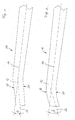
- FIG. 1 an inventive rotor blade 10 of a wind turbine is shown.
- the threading axis 14 is indicated.
- the threading axis 14 is an imaginary axis to which all parts of a rotor blade 10 are to be threaded so that the desired rotor blade shape results.
- the end region 12 of the rotor blade 10 is bent at a predetermined angle ⁇ relative to a first threading axis 14.
- a second threading axis 16 is shown and between the two threading axes 14, 16, the angle ⁇ is indicated. This amount in this FIG. 5 Degree. This measure represents an acceptable compromise between reduced acoustic emission and increased stress.
- the end region in the rotor blade plane is bent in the direction of the rotor blade trailing edge 20.
- This kinking leads on the one hand to a longer trailing edge and thus to a wider distribution of the vortex energy.
- the flow dissolves at the trailing edge of the rotor blade 10 in the bent end portion 12 later than in the straight portion of the rotor blade 10. This causes the noise generating vortex accordingly later.
- FIG. 2 An improved embodiment of a rotor blade 10 according to the invention is shown in FIG. 2 shown. Also in this figure, the Hurdelachsen 14, 16 are located. However, the transition from the rotor blade 10 into the end region 12 does not take place here in a sharp bend, but runs rather steadily in the form of a curve. However, the curvature increases towards the rotor blade tip. The radius of curvature is thus smaller towards the rotor blade tip.
- the arch tangent in the end region 12, is parallel-displaced at the tip of the rotor blade trailing edge 20 and towards the rotor blade center. Between the threading axes 14, 16, an angle ⁇ is indicated. This is 10 degrees.
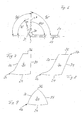
- FIG. 3 This situation is described on the basis of FIG. 3 explained in more detail.
- the end portion 12 of the rotor blade 10 is shown.
- the trailing edge of the end portion 12 is once according to the in FIG. 1 shown bent embodiment shown.
- This variant is designated by the reference numeral 21.
- the embodiment with the curved trailing edge 20 is shown.
- the first threading axis 14 original Blattfädelachse
- the parallel-displaced sheet tangent 17 and the second threading axis 16 are registered corresponding to the trailing edge 21 of the end region.
- the angles ⁇ and ⁇ are also shown.
- the angle ⁇ amounts again 5 degrees. It is formed by the first threading axis 14 of the rotor blade 10 and the second threading axis 16 corresponding to the in FIG FIG. 1 shown embodiment of the rotor blade.
- the angle ⁇ is included between the first threading axis 14 and the sheet tangent 17 corresponding to the one in FIG FIG. 2 illustrated embodiment.
- the angle ⁇ is 10 degrees.
- FIG. 2 illustrated embodiment particularly clearly visible.
- FIG. 4 shows again the present invention gefeilte rotor blade 10 with the leading edge 18, the trailing edge 20 and the filed in the direction of the trailing edge 20 end portion 12. Furthermore, in this figure, two lines 22, 23 are shown, the course of the leading edge 18 and the trailing edge 20 without the represent filed end region 12. Already in this figure can be clearly seen to what extent the end portion 12 is filed by the file in the direction of the trailing edge 20 of the rotor blade 10.
- FIG. 5 an alternative embodiment of the rotor blade 10 according to the invention is shown that of the in FIG. 4 is distinguished by a central portion 13, which is filed in the direction of the leading edge 18 of the rotor blade 10.
- this filing in the direction of the front edge 18 is dimensioned such that the outermost point of the end region 12 of the rotor blade filed in the direction of the trailing edge 20 again lies within the dashed line Lines 22, 23 is located, which indicate the imaginary, rectilinear course of the rotor blade in this figure.
- FIG. 6 shows a rotor blade 10 with an edge bow 30 according to the invention, which extends away from the suction side 24 of the rotor blade 10, ie towards the pressure side of the rotor blade 10.
- the upper edge 36 of the edge bend has the smallest possible profile thickness, in order to keep the edge vortex detaching there as low as possible, so that an acoustical emission which is also as small as possible arises.
- the edge bend 30 is preferably bent at an angle of about 60 ° to 90 ° from the horizontal. D. h., He concludes with the rotor blade an angle between 120 ° and 90 °. This area is represented by two upwardly bent sections 30, 31, one of which is shown with a dashed line.
- FIG. 7 a first embodiment of the edge bow 30 according to the invention is shown in front view.
- the trailing edge 34 of the edge bow 30 and the top edge 36 of the edge bow is straight, while the leading edge 32 extends between the rotor blade leading edge 26 and the edge arc top edge 36 of the suction side 24 of the rotor blade with a predetermined angle.
- the edge-arc top edge 36 shortens with respect to the depth of the rotor blade, recognizable by the rotor blade suction side 24.
- the rotor blade thus has its aerodynamically fully effective depth up to the edge bend 30 and only passes into the edge bend 30 in a shorter edge-arc top edge 36.
- FIG. 8 shows an alternative embodiment of the in FIG. 7 shown edge bow. While in FIG. 7 a substantially perpendicular to the rotor blade longitudinal axis extending edge arc trailing edge 34 is shown, is also this edge bow in FIG. 8 filed in the direction of the trailing edge 34. As a result of this filing, the detachment point 37, in which the flow separates from this edge bend, is displaced even further back, and accordingly the energy of the edge vortex is distributed even further and the acoustic emission is reduced even further.
- edge bow 30 The operating principle is at the in FIG. 9 shown embodiment of the edge bow 30 similar.
- this edge bow 30 is optimized for the smallest possible edge vortex out.
- the edge-arc leading edge 32 and the edge-arc trailing edge 34 run with a predetermined curved, particularly preferably elliptical gradient towards the edge-arc top edge 36.
- the edge-arc top edge 36 is in turn away from the rotor blade suction side 24, that is to say bent out of the rotor blade plane toward the pressure side.
- edge-arc leading edge 32 and the edge-arc trailing edge 34 Due to the elliptical design of the edge-arc leading edge 32 and the edge-arc trailing edge 34, the distance is simultaneously extended at which the flow from the rotor blade dissolves. This also leads to a reduced noise emission, since a flow around the blade tip is largely eliminated unlike blunt leaking blade geometries.
- the ratio of depth to height (the depth is in Fig. 9 in the plan view, the width) of the angled portion of the edge bow is about 1: 0.8 to 1.2, preferably 1: 1.
- the ratio of the height of the bent portion of the edge sheet to the depth of the rotor blade at the end of the edge bend is about 1: 1 to 1: 1.3, preferably 1: 1.14.
- the depth profile in the angled portion of the edge bow is approximately hyperbolic (in the plan view, the profile width) and the uppermost cap point of the outermost profile section is about 30 to 40%, preferably 33% tread depth, based on the Desidelachse of the sheet.
- FIG. 10 shows a rotor blade 10 with a combination of bent end portion 12 and adjoining edge bow 30.
- the bending of the end portion 12 of the leading edge 26 of the rotor blade toward the trailing edge 20 and a bend of the edge bow 30 from the rotor blade plane is clearly visible. Accordingly, here merge the advantageous acoustic effects of the bent end portion 12 on the one hand and the angled edge bow 30 on the other.
- the described rotor blade according to the invention is part of a rotor of a wind energy plant.
Landscapes
- Engineering & Computer Science (AREA)
- Life Sciences & Earth Sciences (AREA)
- Sustainable Development (AREA)
- Sustainable Energy (AREA)
- Chemical & Material Sciences (AREA)
- Combustion & Propulsion (AREA)
- Mechanical Engineering (AREA)
- General Engineering & Computer Science (AREA)
- Physics & Mathematics (AREA)
- Fluid Mechanics (AREA)
- Wind Motors (AREA)
- Turbine Rotor Nozzle Sealing (AREA)
Applications Claiming Priority (4)
| Application Number | Priority Date | Filing Date | Title |
|---|---|---|---|
| DE10300284A DE10300284A1 (de) | 2003-01-02 | 2003-01-02 | Rotorblatt für eine Windenergieanlage |
| DE10303824 | 2003-01-31 | ||
| PCT/EP2003/014621 WO2004061298A2 (fr) | 2003-01-02 | 2003-12-19 | Pale de rotor concue pour une installation d'energie eolienne |
| EP03814464.8A EP1583904B1 (fr) | 2003-01-02 | 2003-12-19 | Pale de rotor concue pour une installation d'energie eolienne |
Related Parent Applications (2)
| Application Number | Title | Priority Date | Filing Date |
|---|---|---|---|
| EP03814464.8A Division EP1583904B1 (fr) | 2003-01-02 | 2003-12-19 | Pale de rotor concue pour une installation d'energie eolienne |
| EP03814464.8 Division | 2003-12-19 |
Publications (3)
| Publication Number | Publication Date |
|---|---|
| EP2469077A2 true EP2469077A2 (fr) | 2012-06-27 |
| EP2469077A3 EP2469077A3 (fr) | 2014-08-27 |
| EP2469077B1 EP2469077B1 (fr) | 2020-05-27 |
Family
ID=32714770
Family Applications (2)
| Application Number | Title | Priority Date | Filing Date |
|---|---|---|---|
| EP12159358.6A Expired - Lifetime EP2469077B1 (fr) | 2003-01-02 | 2003-12-19 | Éolienne avec pale de rotor |
| EP03814464.8A Expired - Lifetime EP1583904B1 (fr) | 2003-01-02 | 2003-12-19 | Pale de rotor concue pour une installation d'energie eolienne |
Family Applications After (1)
| Application Number | Title | Priority Date | Filing Date |
|---|---|---|---|
| EP03814464.8A Expired - Lifetime EP1583904B1 (fr) | 2003-01-02 | 2003-12-19 | Pale de rotor concue pour une installation d'energie eolienne |
Country Status (19)
| Country | Link |
|---|---|
| US (3) | US7540716B2 (fr) |
| EP (2) | EP2469077B1 (fr) |
| JP (1) | JP4282605B2 (fr) |
| KR (3) | KR20080022602A (fr) |
| AR (4) | AR042681A1 (fr) |
| AU (1) | AU2003296688B2 (fr) |
| BR (1) | BR0317775B1 (fr) |
| CA (1) | CA2511052C (fr) |
| CY (1) | CY1114854T1 (fr) |
| DK (2) | DK2469077T3 (fr) |
| ES (1) | ES2440218T3 (fr) |
| MA (1) | MA27571A1 (fr) |
| MX (1) | MXPA05007120A (fr) |
| NO (1) | NO20053711L (fr) |
| NZ (1) | NZ540818A (fr) |
| PL (1) | PL220895B1 (fr) |
| PT (2) | PT1583904E (fr) |
| SI (1) | SI1583904T1 (fr) |
| WO (1) | WO2004061298A2 (fr) |
Families Citing this family (111)
| Publication number | Priority date | Publication date | Assignee | Title |
|---|---|---|---|---|
| ES2440218T3 (es) * | 2003-01-02 | 2014-01-28 | Wobben Properties Gmbh | Pala de rotor de turbina eólica con emisión de ruido reducida |
| US7344360B2 (en) * | 2004-09-29 | 2008-03-18 | General Electric Company | Wind turbine rotor blade with in-plane sweep and devices using same, and methods for making same |
| JP4740580B2 (ja) * | 2004-11-30 | 2011-08-03 | 株式会社ベルシオン | 横軸風車のブレード並びに横軸風車 |
| US8128338B2 (en) | 2004-11-30 | 2012-03-06 | Kabushiki Kaisha Bellsion | Propeller and horizontal-axis wind turbine |
| US9424392B2 (en) | 2005-11-26 | 2016-08-23 | Natera, Inc. | System and method for cleaning noisy genetic data from target individuals using genetic data from genetically related individuals |
| US11111544B2 (en) | 2005-07-29 | 2021-09-07 | Natera, Inc. | System and method for cleaning noisy genetic data and determining chromosome copy number |
| US11111543B2 (en) | 2005-07-29 | 2021-09-07 | Natera, Inc. | System and method for cleaning noisy genetic data and determining chromosome copy number |
| US7730785B2 (en) * | 2006-04-26 | 2010-06-08 | Denso Corporation | Ultrasonic sensor and manufacture method of the same |
| WO2007147177A2 (fr) * | 2006-06-12 | 2007-12-21 | Martin Steyn | Pale |
| DE102006055090A1 (de) * | 2006-11-21 | 2008-05-29 | Airbus Deutschland Gmbh | Flügelendform für einen Flügel, insbesondere von Luftfahrzeugen |
| CN101622446B (zh) * | 2006-12-22 | 2011-12-28 | 维斯塔斯风力系统有限公司 | 带有设置小翼的转子叶片的风轮机及用于这种转子的叶片 |
| EP2169217A4 (fr) * | 2007-02-28 | 2013-12-11 | Gamesa Innovation & Tech Sl | Pale pour éoliennes |
| EP2129908B1 (fr) | 2007-03-20 | 2010-12-01 | Vestas Wind Systems A/S | Pales d'éolienne à générateurs de vortex |
| US7927078B2 (en) * | 2007-07-12 | 2011-04-19 | General Electric Company | Wind turbine blade tip vortex breakers |
| US8197218B2 (en) * | 2007-11-08 | 2012-06-12 | Alliance For Sustainable Energy, Llc | Quiet airfoils for small and large wind turbines |
| WO2009066360A1 (fr) | 2007-11-19 | 2009-05-28 | Mitsubishi Heavy Industries, Ltd. | Aube d'éolienne et aérogénérateur l'utilisant |
| US7654144B2 (en) * | 2007-12-13 | 2010-02-02 | Korea Electric Power Corporation | Nondestructive testing apparatus for blade root of steam turbine of power plant |
| JP2009177088A (ja) * | 2008-01-28 | 2009-08-06 | Tokyo Electron Ltd | 基板処理装置 |
| CN101970803A (zh) * | 2008-02-14 | 2011-02-09 | 丹尼尔·法伯 | 带冠涡轮叶片设计 |
| US8061996B2 (en) * | 2008-05-30 | 2011-11-22 | General Electric Company | Wind turbine blade planforms with twisted and tapered tips |
| US8408877B2 (en) | 2008-05-30 | 2013-04-02 | General Electric Company | Wind turbine blades with twisted tips |
| US8419371B2 (en) | 2008-05-30 | 2013-04-16 | General Electric Company | Wind turbine blades with twisted and tapered tips |
| US8714928B2 (en) * | 2008-06-06 | 2014-05-06 | General Electric Company | Rotor assembly for a wind turbine and method of assembling the same |
| ES3040742T3 (en) | 2008-06-20 | 2025-11-04 | Aviation Partners Inc | Curved wing tip |
| US9302766B2 (en) | 2008-06-20 | 2016-04-05 | Aviation Partners, Inc. | Split blended winglet |
| US7942640B2 (en) * | 2009-03-19 | 2011-05-17 | General Electric Company | Method and apparatus for use in protecting wind turbine blades from lightning damage |
| US7988421B2 (en) * | 2009-03-31 | 2011-08-02 | General Electric Company | Retrofit sleeve for wind turbine blade |
| US8708642B2 (en) * | 2009-04-17 | 2014-04-29 | Romeo Prasad | Stable wind power turbine |
| DE102009019542A1 (de) * | 2009-04-30 | 2010-11-11 | Airbus Deutschland Gmbh | Nicht-planares Flügelendstück für Tragflügel von Flugzeugen sowie Tragflügel mit einem solchen Flügelendstück |
| JP4918664B2 (ja) * | 2009-06-08 | 2012-04-18 | 李佳原 | 風力発電機 |
| US8328516B2 (en) * | 2009-09-29 | 2012-12-11 | General Electric Company | Systems and methods of assembling a rotor blade extension for use in a wind turbine |
| DE102009060650A1 (de) * | 2009-12-22 | 2011-06-30 | Keller, Walter, 66994 | Aeroakustisches Rotorblatt für eine Windkraftanlage sowie damit ausgestattete Windkraftanlage |
| US20110255974A1 (en) * | 2010-04-15 | 2011-10-20 | General Electric Company | Configurable winglet for wind turbine blades |
| US12221653B2 (en) | 2010-05-18 | 2025-02-11 | Natera, Inc. | Methods for simultaneous amplification of target loci |
| US12152275B2 (en) | 2010-05-18 | 2024-11-26 | Natera, Inc. | Methods for non-invasive prenatal ploidy calling |
| US20190010543A1 (en) | 2010-05-18 | 2019-01-10 | Natera, Inc. | Methods for simultaneous amplification of target loci |
| US10316362B2 (en) | 2010-05-18 | 2019-06-11 | Natera, Inc. | Methods for simultaneous amplification of target loci |
| US11326208B2 (en) | 2010-05-18 | 2022-05-10 | Natera, Inc. | Methods for nested PCR amplification of cell-free DNA |
| US11339429B2 (en) | 2010-05-18 | 2022-05-24 | Natera, Inc. | Methods for non-invasive prenatal ploidy calling |
| US9677118B2 (en) | 2014-04-21 | 2017-06-13 | Natera, Inc. | Methods for simultaneous amplification of target loci |
| US11322224B2 (en) | 2010-05-18 | 2022-05-03 | Natera, Inc. | Methods for non-invasive prenatal ploidy calling |
| US11939634B2 (en) | 2010-05-18 | 2024-03-26 | Natera, Inc. | Methods for simultaneous amplification of target loci |
| US11408031B2 (en) | 2010-05-18 | 2022-08-09 | Natera, Inc. | Methods for non-invasive prenatal paternity testing |
| US11332785B2 (en) | 2010-05-18 | 2022-05-17 | Natera, Inc. | Methods for non-invasive prenatal ploidy calling |
| US11332793B2 (en) | 2010-05-18 | 2022-05-17 | Natera, Inc. | Methods for simultaneous amplification of target loci |
| WO2011146632A1 (fr) | 2010-05-18 | 2011-11-24 | Gene Security Network Inc. | Procédés de classification de ploïdie prénatale non invasive |
| US8043066B2 (en) | 2010-06-08 | 2011-10-25 | General Electric Company | Trailing edge bonding cap for wind turbine rotor blades |
| JP5158730B2 (ja) * | 2010-06-30 | 2013-03-06 | 株式会社日本製鋼所 | 風力発電用ブレードの避雷構造 |
| GB201011843D0 (en) * | 2010-07-14 | 2010-09-01 | Airbus Operations Ltd | Wing tip device |
| US7946826B1 (en) | 2010-07-16 | 2011-05-24 | General Electric Company | Wind turbine rotor blade with a suction side winglet |
| EP2416005A1 (fr) * | 2010-08-02 | 2012-02-08 | Siemens Aktiengesellschaft | Agencement pour la protection contre la foudre de la pale d'une éolienne |
| DE102010040596A1 (de) * | 2010-09-10 | 2012-03-15 | Aloys Wobben | Abnehmbare Rotorblattspitze |
| US7997875B2 (en) | 2010-11-16 | 2011-08-16 | General Electric Company | Winglet for wind turbine rotor blade |
| US20110243736A1 (en) * | 2010-12-08 | 2011-10-06 | General Electric Company | Joint sleeve for a rotor blade assembly of a wind turbine |
| US8317483B2 (en) * | 2010-12-15 | 2012-11-27 | General Electric Company | Wind turbine rotor blade |
| CN103608466B (zh) | 2010-12-22 | 2020-09-18 | 纳特拉公司 | 非侵入性产前亲子鉴定方法 |
| RU2671980C2 (ru) | 2011-02-09 | 2018-11-08 | Натера, Инк. | Способы неинвазивного пренатального установления плоидности |
| JP5602060B2 (ja) * | 2011-02-28 | 2014-10-08 | 三菱重工業株式会社 | 風車翼およびこれを備えた風力発電装置ならびに風車翼の設計方法 |
| DE102012103704B4 (de) | 2011-04-30 | 2025-11-06 | General Electric Renovables España, S.L. | Winglet für einen Rotorflügel einer Windkraftanlage |
| KR101331103B1 (ko) * | 2011-05-20 | 2013-11-19 | 성광기전주식회사 | 실내 순환용 팬블레이드와 이를 이용한 순환장치 |
| DK3650337T3 (da) * | 2011-06-09 | 2021-02-22 | Aviation Partners Inc | Delt "blended" winglet |
| KR101291663B1 (ko) * | 2011-09-29 | 2013-08-01 | 삼성중공업 주식회사 | 블레이드 및 그것을 구비한 풍력발전기 |
| US9920741B2 (en) | 2012-01-25 | 2018-03-20 | Siemens Aktiengesellschaft | Wind turbine blade having a geometric sweep |
| US9103325B2 (en) | 2012-03-20 | 2015-08-11 | General Electric Company | Winglet for a wind turbine rotor blade |
| US9109578B2 (en) | 2012-06-12 | 2015-08-18 | General Electric Company | Root extender for a wind turbine rotor blade |
| US9074581B2 (en) | 2012-06-12 | 2015-07-07 | General Electric Company | Cone angle insert for wind turbine rotor |
| US20140100126A1 (en) | 2012-08-17 | 2014-04-10 | Natera, Inc. | Method for Non-Invasive Prenatal Testing Using Parental Mosaicism Data |
| DE102013205965A1 (de) | 2013-04-04 | 2014-10-30 | Wobben Properties Gmbh | Rotorblattspitze |
| JP6009058B2 (ja) * | 2013-02-26 | 2016-10-19 | 三菱重工業株式会社 | 風車翼及びこれを備えた風力発電装置 |
| JP6189088B2 (ja) * | 2013-05-28 | 2017-08-30 | テラル株式会社 | ロータ |
| US9366224B2 (en) | 2013-06-27 | 2016-06-14 | General Electric Company | Wind turbine blade and method of fabricating the same |
| US20150132141A1 (en) * | 2013-11-08 | 2015-05-14 | Siemens Aktiengesellschaft | Rotor blade of a wind turbine |
| US10562613B2 (en) * | 2013-12-04 | 2020-02-18 | Tamarack Aerospace Group, Inc. | Adjustable lift modification wingtip |
| WO2015145723A1 (fr) * | 2014-03-28 | 2015-10-01 | 中国電力株式会社 | Pale de turbine éolienne et générateur d'énergie éolienne la comportant |
| CA2945962C (fr) | 2014-04-21 | 2023-08-29 | Natera, Inc. | Detection de mutations et de la ploidie dans des segments chromosomiques |
| US20180173846A1 (en) | 2014-06-05 | 2018-06-21 | Natera, Inc. | Systems and Methods for Detection of Aneuploidy |
| BR112017002319B1 (pt) * | 2014-08-05 | 2022-09-13 | Ryan Church | Estrutura com aleta rígida adaptada para atravessar um ambiente fluido, turbina e aeronave |
| DE102014115524A1 (de) | 2014-10-24 | 2016-04-28 | Nordex Energy Gmbh | Windenergieanlagenrotorblatt mit einem Winglet |
| US11479812B2 (en) | 2015-05-11 | 2022-10-25 | Natera, Inc. | Methods and compositions for determining ploidy |
| PL3377775T3 (pl) * | 2015-11-16 | 2022-09-19 | R.E.M. Holding S.R.L. | Przemysłowy wentylator osiowy z łopatami o niskim poziomie hałasu i dużej wydajności |
| US10287006B1 (en) * | 2015-12-18 | 2019-05-14 | Amazon Technologies, Inc. | Adjustable propeller blades for sound control |
| US9592910B1 (en) | 2015-12-18 | 2017-03-14 | Amazon Technologies, Inc. | Geometrically reconfigurable propellers |
| US10370098B1 (en) * | 2015-12-18 | 2019-08-06 | Amazon Technologies, Inc. | Adjustable propeller blade with sound flaps |
| JP7049050B2 (ja) * | 2016-02-24 | 2022-04-06 | Ntn株式会社 | ロータブレード |
| JP2017166373A (ja) * | 2016-03-15 | 2017-09-21 | クリーンエナジーファクトリー株式会社 | 風力発電機 |
| RU2760913C2 (ru) | 2016-04-15 | 2021-12-01 | Натера, Инк. | Способы выявления рака легкого |
| US20170342990A1 (en) * | 2016-05-26 | 2017-11-30 | Perry Lynn Martens | Waste air flow capture system |
| EP3269635A1 (fr) * | 2016-07-12 | 2018-01-17 | The Aircraft Performance Company UG | Aile d'avion |
| DE102016113574A1 (de) | 2016-07-22 | 2018-01-25 | Wobben Properties Gmbh | Windenergieanlagen-Rotorblatt und Windenergieanlagen-Rotorblattspitze |
| WO2018067517A1 (fr) | 2016-10-04 | 2018-04-12 | Natera, Inc. | Procédés pour caractériser une variation de nombre de copies à l'aide d'un séquençage de ligature de proximité |
| GB201618485D0 (en) | 2016-11-02 | 2016-12-14 | Ucl Business Plc | Method of detecting tumour recurrence |
| US10011870B2 (en) | 2016-12-07 | 2018-07-03 | Natera, Inc. | Compositions and methods for identifying nucleic acid molecules |
| US10961982B2 (en) | 2017-11-07 | 2021-03-30 | General Electric Company | Method of joining blade sections using thermoplastics |
| CN109899230A (zh) * | 2017-12-07 | 2019-06-18 | 代元军 | 一种叶片叶尖呈融合式结构的风力机叶片及风力机 |
| US12084720B2 (en) | 2017-12-14 | 2024-09-10 | Natera, Inc. | Assessing graft suitability for transplantation |
| ES2905192T3 (es) * | 2018-01-15 | 2022-04-07 | The Aircraft Performance Company Gmbh | Ala de avión |
| US12024738B2 (en) | 2018-04-14 | 2024-07-02 | Natera, Inc. | Methods for cancer detection and monitoring |
| JP6426869B1 (ja) * | 2018-06-08 | 2018-11-21 | 株式会社グローバルエナジー | 横軸ロータ |
| US12234509B2 (en) | 2018-07-03 | 2025-02-25 | Natera, Inc. | Methods for detection of donor-derived cell-free DNA |
| DK3686423T3 (da) * | 2019-01-22 | 2023-02-27 | Wepfer Technics Ag | Rotorvinge til en vindmølle |
| US12305235B2 (en) | 2019-06-06 | 2025-05-20 | Natera, Inc. | Methods for detecting immune cell DNA and monitoring immune system |
| GB202020710D0 (en) | 2020-12-30 | 2021-02-10 | Gen Electric | Method of joining segments of a composite component |
| CN117280113A (zh) * | 2021-03-10 | 2023-12-22 | 维斯塔斯风力系统有限公司 | 风力涡轮机叶片 |
| IT202100032258A1 (it) * | 2021-12-22 | 2023-06-22 | Cofimco Srl | Pala di ventilatore assiale industriale |
| GB2615311A (en) * | 2022-01-31 | 2023-08-09 | Airbus Operations Ltd | Aircraft wing with movable wing tip device |
| GB2616252A (en) * | 2022-01-31 | 2023-09-06 | Airbus Operations Ltd | Aircraft with movable wing tip device |
| CN119422002A (zh) * | 2022-06-22 | 2025-02-11 | 维斯塔斯风力系统集团公司 | 风力涡轮机叶片系列 |
| GB2628523B (en) * | 2022-11-16 | 2025-07-09 | Airbus Operations Ltd | Aircraft wing |
| US11988187B1 (en) | 2023-07-13 | 2024-05-21 | United Arab Emirates University | Wind turbine blade with self-adaptive tip-sweep |
| WO2025178957A1 (fr) * | 2024-02-23 | 2025-08-28 | Amarillo Gear Company Llc | Pale de ventilateur agricole |
| EP4628724A1 (fr) * | 2024-04-04 | 2025-10-08 | Nordex Energy SE & Co. KG | Une pale de rotor d'éolienne avec une section d'extrémité |
Citations (5)
| Publication number | Priority date | Publication date | Assignee | Title |
|---|---|---|---|---|
| DE4436197A1 (de) | 1994-10-11 | 1996-04-18 | Aloys Wobben | Windenergieanlage mit Blitzschutzeinrichtung |
| DE4440744A1 (de) | 1994-11-15 | 1996-05-23 | Peter Frieden | Rotorblatt eines Rotors für Windkraftanlagen |
| DE19614420A1 (de) | 1996-04-12 | 1997-10-16 | Aloys Wobben | Rotorblatt und Windenergieanlage mit einem Rotorblatt |
| DE19738278A1 (de) | 1997-09-02 | 1999-03-04 | Felix Hafner | Adaptiver Rotor für Windkraftanlagen |
| DE19743694A1 (de) | 1997-10-02 | 1999-04-15 | Aloys Wobben | Rotorblatt und Windenergieanlage mit einem Rotorblatt |
Family Cites Families (44)
| Publication number | Priority date | Publication date | Assignee | Title |
|---|---|---|---|---|
| US453329A (en) * | 1891-06-02 | Spirit-level | ||
| US432453A (en) * | 1890-07-15 | Island | ||
| US2426742A (en) * | 1943-11-20 | 1947-09-02 | Felix W Pawlowski | Screw propeller |
| US3171495A (en) * | 1963-04-22 | 1965-03-02 | William H Puckett | Propeller |
| US3411738A (en) | 1966-10-27 | 1968-11-19 | William E. Sargent | Airfoil tip |
| NL174287C (nl) | 1974-06-10 | 1984-05-16 | Theodoor Van Holten | Rotor voor een windturbine. |
| FR2292878A1 (fr) * | 1974-09-30 | 1976-06-25 | Sahores Jean | Moteur eolien |
| US4168939A (en) | 1977-09-08 | 1979-09-25 | The United States Of America As Represented By The Administrator Of The National Aeronautics And Space Administration | Acoustically swept rotor |
| US4291235A (en) | 1979-02-26 | 1981-09-22 | Bergey Jr Karl H | Windmill |
| DE2944718A1 (de) * | 1979-11-06 | 1981-05-21 | Hans-Dietrich Ing.(grad.) 2000 Hamburg Goslich | Rotor fuer windkraftanlagen in leichtbauweise |
| US4324530A (en) | 1980-01-21 | 1982-04-13 | United Technologies Corp. | Helicopter blade with a tip having a selected combination of sweep, taper and anhedral to improve hover efficiency |
| JPS56143369A (en) * | 1980-04-07 | 1981-11-09 | Agency Of Ind Science & Technol | Wind force prime mover using propeller |
| US4329115A (en) * | 1981-02-02 | 1982-05-11 | Grumman Aerospace Corporation | Directionally stabilized wind turbine |
| US4533297A (en) | 1982-09-15 | 1985-08-06 | Bassett David A | Rotor system for horizontal axis wind turbines |
| GB8310224D0 (en) | 1983-04-15 | 1983-05-18 | British Aerospace | Wing tip arrangement |
| US5525269A (en) * | 1985-03-22 | 1996-06-11 | Philadelphia Gear Corporation | Impeller tiplets for improving gas to liquid mass transfer efficiency in a draft tube submerged turbine mixer/aerator |
| US4722608A (en) * | 1985-07-30 | 1988-02-02 | General Signal Corp. | Mixing apparatus |
| US4776542A (en) | 1987-05-27 | 1988-10-11 | Vigyan Research Associates, Inc. | Aircraft stall-spin entry deterrent system |
| US5217349A (en) * | 1989-08-31 | 1993-06-08 | Technology Integration Incorporated | System and method for suppressing noise produced by rotors |
| DE4030559A1 (de) | 1990-09-27 | 1992-04-02 | Schubert Werner | Windturbine zur besseren ausnutzung der windkraft |
| DE4136956A1 (de) | 1990-09-27 | 1993-05-13 | Schubert Werner | Windturbine |
| JP3102494B2 (ja) | 1990-09-28 | 2000-10-23 | 株式会社日立製作所 | 信号検出回路 |
| IL101069A (en) | 1991-02-25 | 1996-09-12 | Valsan Partners Purchase N Y | A system for increasing the fuel efficiency of an aircraft and a kit for changing aircraft wings |
| JPH04317892A (ja) | 1991-04-17 | 1992-11-09 | Mitsubishi Heavy Ind Ltd | ヘリコプタ・ロータ・ブレード |
| US5215441A (en) * | 1991-11-07 | 1993-06-01 | Carrier Corporation | Air conditioner with condensate slinging fan |
| GB2265672B (en) | 1992-03-18 | 1995-11-22 | Advanced Wind Turbines Inc | Wind turbines |
| US5348253A (en) | 1993-02-01 | 1994-09-20 | Gratzer Louis B | Blended winglet |
| US5525569A (en) * | 1994-03-07 | 1996-06-11 | Moore Business Forms, Inc. | Self-contained transfer tape |
| US5584661A (en) | 1994-05-02 | 1996-12-17 | The United States Of America As Represented By The Administrator Of The National Aeronautics And Space Administration | Forward sweep, low noise rotor blade |
| US5634613A (en) | 1994-07-18 | 1997-06-03 | Mccarthy; Peter T. | Tip vortex generation technology for creating a lift enhancing and drag reducing upwash effect |
| ES2232959T3 (es) | 1997-09-04 | 2005-06-01 | Lm Glasfiber A/S | Rotor de molino de viento y aspas para el mismo. |
| FR2768121B1 (fr) * | 1997-09-10 | 1999-11-19 | Onera (Off Nat Aerospatiale) | Pale a signature sonore reduite, pour voilure tournante d'aeronef, et voilure tournante comportant une telle pale |
| US6068446A (en) * | 1997-11-20 | 2000-05-30 | Midwest Research Institute | Airfoils for wind turbine |
| FR2772715B1 (fr) | 1997-12-22 | 2000-02-11 | Eurocopter France | Pale pour aeronef a voilure tournante |
| US6334705B1 (en) * | 1998-10-01 | 2002-01-01 | General Signal Corporation | Fluid mixing impellers with shear generating venturi |
| DE19926832B4 (de) | 1999-06-12 | 2005-09-15 | Airbus Deutschland Gmbh | Unterschallflugzeug vorzugsweise mit gepfeilten Tragflügeln |
| DE19963252A1 (de) * | 1999-12-17 | 2001-07-12 | Lutz Schulze | Längsachsial verändertes Rotorblatt zur Erhöhung der Rotorleistung für HA-Windturbinen |
| US6484968B2 (en) * | 2000-12-11 | 2002-11-26 | Fort F. Felker | Aircraft with elliptical winglets |
| DK174232B1 (da) * | 2000-12-13 | 2002-10-07 | Lm Glasfiber As | Kombineret lynreceptor og drænkanal i vindmøllevinge |
| DE10117721B4 (de) * | 2001-04-09 | 2007-09-27 | Gerd Heller | Flügelspitzenverlängerung für einen Flügel |
| US6517315B2 (en) * | 2001-05-29 | 2003-02-11 | Hewlett-Packard Company | Enhanced performance fan with the use of winglets |
| US6547181B1 (en) * | 2002-05-29 | 2003-04-15 | The Boeing Company | Ground effect wing having a variable sweep winglet |
| US6688842B2 (en) * | 2002-06-24 | 2004-02-10 | Bruce E. Boatner | Vertical axis wind engine |
| ES2440218T3 (es) * | 2003-01-02 | 2014-01-28 | Wobben Properties Gmbh | Pala de rotor de turbina eólica con emisión de ruido reducida |
-
2003
- 2003-12-19 ES ES03814464.8T patent/ES2440218T3/es not_active Expired - Lifetime
- 2003-12-19 CA CA002511052A patent/CA2511052C/fr not_active Expired - Lifetime
- 2003-12-19 KR KR1020087004646A patent/KR20080022602A/ko not_active Withdrawn
- 2003-12-19 SI SI200332319T patent/SI1583904T1/sl unknown
- 2003-12-19 BR BRPI0317775-0A patent/BR0317775B1/pt not_active IP Right Cessation
- 2003-12-19 DK DK12159358.6T patent/DK2469077T3/da active
- 2003-12-19 MX MXPA05007120A patent/MXPA05007120A/es active IP Right Grant
- 2003-12-19 WO PCT/EP2003/014621 patent/WO2004061298A2/fr not_active Ceased
- 2003-12-19 JP JP2004564207A patent/JP4282605B2/ja not_active Expired - Lifetime
- 2003-12-19 EP EP12159358.6A patent/EP2469077B1/fr not_active Expired - Lifetime
- 2003-12-19 KR KR1020087006423A patent/KR100917773B1/ko not_active Expired - Fee Related
- 2003-12-19 DK DK03814464.8T patent/DK1583904T3/da active
- 2003-12-19 KR KR1020057011897A patent/KR20050088325A/ko not_active Ceased
- 2003-12-19 PT PT38144648T patent/PT1583904E/pt unknown
- 2003-12-19 PL PL377904A patent/PL220895B1/pl unknown
- 2003-12-19 US US10/541,146 patent/US7540716B2/en not_active Expired - Fee Related
- 2003-12-19 NZ NZ540818A patent/NZ540818A/en not_active IP Right Cessation
- 2003-12-19 AU AU2003296688A patent/AU2003296688B2/en not_active Ceased
- 2003-12-19 EP EP03814464.8A patent/EP1583904B1/fr not_active Expired - Lifetime
- 2003-12-19 PT PT121593586T patent/PT2469077T/pt unknown
- 2003-12-30 AR ARP030104866A patent/AR042681A1/es not_active Application Discontinuation
-
2005
- 2005-06-22 MA MA28354A patent/MA27571A1/fr unknown
- 2005-08-01 NO NO20053711A patent/NO20053711L/no not_active Application Discontinuation
-
2008
- 2008-11-11 US US12/268,576 patent/US7841836B2/en not_active Expired - Lifetime
-
2009
- 2009-06-02 AR ARP090101975A patent/AR071985A2/es not_active Application Discontinuation
- 2009-07-31 AR ARP090102935A patent/AR072892A2/es not_active Application Discontinuation
- 2009-07-31 AR ARP090102936A patent/AR072893A2/es not_active Application Discontinuation
-
2010
- 2010-10-25 US US12/911,648 patent/US8241002B2/en not_active Expired - Lifetime
-
2013
- 2013-12-12 CY CY20131101123T patent/CY1114854T1/el unknown
Patent Citations (5)
| Publication number | Priority date | Publication date | Assignee | Title |
|---|---|---|---|---|
| DE4436197A1 (de) | 1994-10-11 | 1996-04-18 | Aloys Wobben | Windenergieanlage mit Blitzschutzeinrichtung |
| DE4440744A1 (de) | 1994-11-15 | 1996-05-23 | Peter Frieden | Rotorblatt eines Rotors für Windkraftanlagen |
| DE19614420A1 (de) | 1996-04-12 | 1997-10-16 | Aloys Wobben | Rotorblatt und Windenergieanlage mit einem Rotorblatt |
| DE19738278A1 (de) | 1997-09-02 | 1999-03-04 | Felix Hafner | Adaptiver Rotor für Windkraftanlagen |
| DE19743694A1 (de) | 1997-10-02 | 1999-04-15 | Aloys Wobben | Rotorblatt und Windenergieanlage mit einem Rotorblatt |
Also Published As
Similar Documents
| Publication | Publication Date | Title |
|---|---|---|
| EP2469077B1 (fr) | Éolienne avec pale de rotor | |
| DE10300284A1 (de) | Rotorblatt für eine Windenergieanlage | |
| DE10347802B3 (de) | Rotorblatt für eine Windkraftanlage | |
| EP1514023B1 (fr) | Eolienne | |
| EP2280163B1 (fr) | Eolienne et pale de rotor d'une eolienne | |
| EP3008331B1 (fr) | Pale de rotor d'une éolienne et éolienne | |
| EP1923567A2 (fr) | Pale d'éolienne et éolienne | |
| EP3330530A1 (fr) | Pale d'éolienne | |
| EP3066337B1 (fr) | Pale de rotor d'une éolienne et éolienne | |
| DE19963086C1 (de) | Rotorblatt für eine Windenergieanlage | |
| EP3169898B1 (fr) | Pale de rotor d'éolienne, bord de fuite de pointe de pale de rotor d'éolienne, procédé de fabrication d'une pale de rotor d'éolienne et éolienne | |
| EP2715117A1 (fr) | Pale courbé du rotor d'une eolienne | |
| DE102017117843A1 (de) | Rotorblatt eines Rotors einer Windenergieanlage, Windenergieanlage und Verfahren zur Verbesserung des Wirkungsgrades eines Rotors einer Windenergieanlage | |
| DE19743694C2 (de) | Rotorblatt und Windenergieanlage mit einem Rotorblatt | |
| EP2568166B1 (fr) | Pale de rotor d'éolienne dotée d'un rebord arrière à profil épais | |
| EP3399183B1 (fr) | Pale de rotor d'une éolienne | |
| EP2927476A1 (fr) | Rotor et turbine à entraînement fluidique dotée de rotor | |
| DE102013204879A1 (de) | Rotorblatt einer Windenergieanlage, Windenergieanlage und Verfahren zum Betreiben einer Windenergieanlage | |
| DE102020207914A1 (de) | Ventilator sowie Flügel und Flügelrad für einen Ventilator | |
| EP3969741B1 (fr) | Pale de rotor et éolienne | |
| EP3735530B1 (fr) | Pale de rotor pour éolienne et procédé | |
| EP3553306A1 (fr) | Pale de rotor d'une éolienne pourvue d'un générateur de vortex | |
| DE102008048612B4 (de) | Einlaufrechen für Wasserentnahmebauwerke, zum Beispiel Wasserkraftwerke, wobei der Einlaufrechen vor dem Einlauf zu der Turbine angeordnet ist, umfassend mehrere nebeneinander angeordnete Rechenstäbe, die miteinander verbunden sind | |
| EP3399182A1 (fr) | Extrémité de pale silencieuse |
Legal Events
| Date | Code | Title | Description |
|---|---|---|---|
| AC | Divisional application: reference to earlier application |
Ref document number: 1583904 Country of ref document: EP Kind code of ref document: P |
|
| AK | Designated contracting states |
Kind code of ref document: A2 Designated state(s): AT BE BG CH CY CZ DE DK EE ES FI FR GB GR HU IE IT LI LU MC NL PT RO SE SI SK TR |
|
| AX | Request for extension of the european patent |
Extension state: LT LV |
|
| PUAI | Public reference made under article 153(3) epc to a published international application that has entered the european phase |
Free format text: ORIGINAL CODE: 0009012 |
|
| PUAL | Search report despatched |
Free format text: ORIGINAL CODE: 0009013 |
|
| AK | Designated contracting states |
Kind code of ref document: A3 Designated state(s): AT BE BG CH CY CZ DE DK EE ES FI FR GB GR HU IE IT LI LU MC NL PT RO SE SI SK TR |
|
| AX | Request for extension of the european patent |
Extension state: LT LV |
|
| RIC1 | Information provided on ipc code assigned before grant |
Ipc: B64C 27/46 20060101ALI20140718BHEP Ipc: F03D 1/06 20060101AFI20140718BHEP |
|
| 17P | Request for examination filed |
Effective date: 20150227 |
|
| RAX | Requested extension states of the european patent have changed |
Extension state: LV Payment date: 20150227 Extension state: LT Payment date: 20150227 |
|
| RBV | Designated contracting states (corrected) |
Designated state(s): AT BE BG CH CY CZ DE DK EE ES FI FR GB GR HU IE IT LI LU MC NL PT RO SE SI SK TR |
|
| RAP1 | Party data changed (applicant data changed or rights of an application transferred) |
Owner name: WOBBEN PROPERTIES GMBH |
|
| RIN1 | Information on inventor provided before grant (corrected) |
Inventor name: WOBBEN PROPERTIES GMBH |
|
| RAP1 | Party data changed (applicant data changed or rights of an application transferred) |
Owner name: WOBBEN PROPERTIES GMBH |
|
| RIN1 | Information on inventor provided before grant (corrected) |
Inventor name: WOBBEN PROPERTIES GMBH |
|
| RIN1 | Information on inventor provided before grant (corrected) |
Inventor name: DER ERFINDER HAT AUF SEINE NENNUNG VERZICHTET. |
|
| RIN1 | Information on inventor provided before grant (corrected) |
Inventor name: WOBBEN, ALOYS |
|
| STAA | Information on the status of an ep patent application or granted ep patent |
Free format text: STATUS: EXAMINATION IS IN PROGRESS |
|
| 17Q | First examination report despatched |
Effective date: 20170705 |
|
| GRAP | Despatch of communication of intention to grant a patent |
Free format text: ORIGINAL CODE: EPIDOSNIGR1 |
|
| STAA | Information on the status of an ep patent application or granted ep patent |
Free format text: STATUS: GRANT OF PATENT IS INTENDED |
|
| INTG | Intention to grant announced |
Effective date: 20200127 |
|
| GRAS | Grant fee paid |
Free format text: ORIGINAL CODE: EPIDOSNIGR3 |
|
| GRAA | (expected) grant |
Free format text: ORIGINAL CODE: 0009210 |
|
| STAA | Information on the status of an ep patent application or granted ep patent |
Free format text: STATUS: THE PATENT HAS BEEN GRANTED |
|
| REG | Reference to a national code |
Ref country code: DE Ref legal event code: R082 Ref document number: 50315887 Country of ref document: DE Representative=s name: EISENFUEHR SPEISER PATENTANWAELTE RECHTSANWAEL, DE Ref country code: DE Ref legal event code: R081 Ref document number: 50315887 Country of ref document: DE Owner name: WOBBEN PROPERTIES GMBH, DE Free format text: FORMER OWNER: WOBBEN PROPERTIES GMBH, 26605 AURICH, DE |
|
| AC | Divisional application: reference to earlier application |
Ref document number: 1583904 Country of ref document: EP Kind code of ref document: P |
|
| AK | Designated contracting states |
Kind code of ref document: B1 Designated state(s): AT BE BG CH CY CZ DE DK EE ES FI FR GB GR HU IE IT LI LU MC NL PT RO SE SI SK TR |
|
| AX | Request for extension of the european patent |
Extension state: LT LV |
|
| REG | Reference to a national code |
Ref country code: GB Ref legal event code: FG4D Free format text: NOT ENGLISH |
|
| REG | Reference to a national code |
Ref country code: CH Ref legal event code: EP |
|
| REG | Reference to a national code |
Ref country code: DE Ref legal event code: R096 Ref document number: 50315887 Country of ref document: DE |
|
| REG | Reference to a national code |
Ref country code: AT Ref legal event code: REF Ref document number: 1274809 Country of ref document: AT Kind code of ref document: T Effective date: 20200615 |
|
| REG | Reference to a national code |
Ref country code: PT Ref legal event code: SC4A Ref document number: 2469077 Country of ref document: PT Date of ref document: 20200710 Kind code of ref document: T Free format text: AVAILABILITY OF NATIONAL TRANSLATION Effective date: 20200703 |
|
| REG | Reference to a national code |
Ref country code: DK Ref legal event code: T3 Effective date: 20200731 |
|
| REG | Reference to a national code |
Ref country code: LT Ref legal event code: MG9D |
|
| PG25 | Lapsed in a contracting state [announced via postgrant information from national office to epo] |
Ref country code: SE Free format text: LAPSE BECAUSE OF FAILURE TO SUBMIT A TRANSLATION OF THE DESCRIPTION OR TO PAY THE FEE WITHIN THE PRESCRIBED TIME-LIMIT Effective date: 20200527 Ref country code: GR Free format text: LAPSE BECAUSE OF FAILURE TO SUBMIT A TRANSLATION OF THE DESCRIPTION OR TO PAY THE FEE WITHIN THE PRESCRIBED TIME-LIMIT Effective date: 20200828 Ref country code: FI Free format text: LAPSE BECAUSE OF FAILURE TO SUBMIT A TRANSLATION OF THE DESCRIPTION OR TO PAY THE FEE WITHIN THE PRESCRIBED TIME-LIMIT Effective date: 20200527 |
|
| REG | Reference to a national code |
Ref country code: NL Ref legal event code: MP Effective date: 20200527 |
|
| PG25 | Lapsed in a contracting state [announced via postgrant information from national office to epo] |
Ref country code: BG Free format text: LAPSE BECAUSE OF FAILURE TO SUBMIT A TRANSLATION OF THE DESCRIPTION OR TO PAY THE FEE WITHIN THE PRESCRIBED TIME-LIMIT Effective date: 20200827 |
|
| PG25 | Lapsed in a contracting state [announced via postgrant information from national office to epo] |
Ref country code: NL Free format text: LAPSE BECAUSE OF FAILURE TO SUBMIT A TRANSLATION OF THE DESCRIPTION OR TO PAY THE FEE WITHIN THE PRESCRIBED TIME-LIMIT Effective date: 20200527 |
|
| PG25 | Lapsed in a contracting state [announced via postgrant information from national office to epo] |
Ref country code: ES Free format text: LAPSE BECAUSE OF FAILURE TO SUBMIT A TRANSLATION OF THE DESCRIPTION OR TO PAY THE FEE WITHIN THE PRESCRIBED TIME-LIMIT Effective date: 20200527 Ref country code: RO Free format text: LAPSE BECAUSE OF FAILURE TO SUBMIT A TRANSLATION OF THE DESCRIPTION OR TO PAY THE FEE WITHIN THE PRESCRIBED TIME-LIMIT Effective date: 20200527 Ref country code: CZ Free format text: LAPSE BECAUSE OF FAILURE TO SUBMIT A TRANSLATION OF THE DESCRIPTION OR TO PAY THE FEE WITHIN THE PRESCRIBED TIME-LIMIT Effective date: 20200527 Ref country code: EE Free format text: LAPSE BECAUSE OF FAILURE TO SUBMIT A TRANSLATION OF THE DESCRIPTION OR TO PAY THE FEE WITHIN THE PRESCRIBED TIME-LIMIT Effective date: 20200527 Ref country code: IT Free format text: LAPSE BECAUSE OF FAILURE TO SUBMIT A TRANSLATION OF THE DESCRIPTION OR TO PAY THE FEE WITHIN THE PRESCRIBED TIME-LIMIT Effective date: 20200527 |
|
| PG25 | Lapsed in a contracting state [announced via postgrant information from national office to epo] |
Ref country code: SK Free format text: LAPSE BECAUSE OF FAILURE TO SUBMIT A TRANSLATION OF THE DESCRIPTION OR TO PAY THE FEE WITHIN THE PRESCRIBED TIME-LIMIT Effective date: 20200527 |
|
| REG | Reference to a national code |
Ref country code: DE Ref legal event code: R097 Ref document number: 50315887 Country of ref document: DE |
|
| PLBE | No opposition filed within time limit |
Free format text: ORIGINAL CODE: 0009261 |
|
| STAA | Information on the status of an ep patent application or granted ep patent |
Free format text: STATUS: NO OPPOSITION FILED WITHIN TIME LIMIT |
|
| 26N | No opposition filed |
Effective date: 20210302 |
|
| PG25 | Lapsed in a contracting state [announced via postgrant information from national office to epo] |
Ref country code: SI Free format text: LAPSE BECAUSE OF FAILURE TO SUBMIT A TRANSLATION OF THE DESCRIPTION OR TO PAY THE FEE WITHIN THE PRESCRIBED TIME-LIMIT Effective date: 20200527 |
|
| REG | Reference to a national code |
Ref country code: CH Ref legal event code: PL |
|
| PG25 | Lapsed in a contracting state [announced via postgrant information from national office to epo] |
Ref country code: MC Free format text: LAPSE BECAUSE OF FAILURE TO SUBMIT A TRANSLATION OF THE DESCRIPTION OR TO PAY THE FEE WITHIN THE PRESCRIBED TIME-LIMIT Effective date: 20200527 |
|
| REG | Reference to a national code |
Ref country code: BE Ref legal event code: MM Effective date: 20201231 |
|
| PG25 | Lapsed in a contracting state [announced via postgrant information from national office to epo] |
Ref country code: IE Free format text: LAPSE BECAUSE OF NON-PAYMENT OF DUE FEES Effective date: 20201219 Ref country code: LU Free format text: LAPSE BECAUSE OF NON-PAYMENT OF DUE FEES Effective date: 20201219 |
|
| PG25 | Lapsed in a contracting state [announced via postgrant information from national office to epo] |
Ref country code: LI Free format text: LAPSE BECAUSE OF NON-PAYMENT OF DUE FEES Effective date: 20201231 Ref country code: PT Free format text: LAPSE BECAUSE OF NON-PAYMENT OF DUE FEES Effective date: 20210920 Ref country code: CH Free format text: LAPSE BECAUSE OF NON-PAYMENT OF DUE FEES Effective date: 20201231 |
|
| REG | Reference to a national code |
Ref country code: AT Ref legal event code: MM01 Ref document number: 1274809 Country of ref document: AT Kind code of ref document: T Effective date: 20201219 |
|
| PG25 | Lapsed in a contracting state [announced via postgrant information from national office to epo] |
Ref country code: AT Free format text: LAPSE BECAUSE OF NON-PAYMENT OF DUE FEES Effective date: 20201219 |
|
| PG25 | Lapsed in a contracting state [announced via postgrant information from national office to epo] |
Ref country code: TR Free format text: LAPSE BECAUSE OF FAILURE TO SUBMIT A TRANSLATION OF THE DESCRIPTION OR TO PAY THE FEE WITHIN THE PRESCRIBED TIME-LIMIT Effective date: 20200527 Ref country code: CY Free format text: LAPSE BECAUSE OF FAILURE TO SUBMIT A TRANSLATION OF THE DESCRIPTION OR TO PAY THE FEE WITHIN THE PRESCRIBED TIME-LIMIT Effective date: 20200527 |
|
| PG25 | Lapsed in a contracting state [announced via postgrant information from national office to epo] |
Ref country code: BE Free format text: LAPSE BECAUSE OF NON-PAYMENT OF DUE FEES Effective date: 20201231 |
|
| PGFP | Annual fee paid to national office [announced via postgrant information from national office to epo] |
Ref country code: GB Payment date: 20221222 Year of fee payment: 20 Ref country code: FR Payment date: 20221219 Year of fee payment: 20 Ref country code: DK Payment date: 20221221 Year of fee payment: 20 Ref country code: DE Payment date: 20220629 Year of fee payment: 20 |
|
| REG | Reference to a national code |
Ref country code: DE Ref legal event code: R071 Ref document number: 50315887 Country of ref document: DE |
|
| REG | Reference to a national code |
Ref country code: DK Ref legal event code: EUP Expiry date: 20231219 |
|
| REG | Reference to a national code |
Ref country code: GB Ref legal event code: PE20 Expiry date: 20231218 |
|
| PG25 | Lapsed in a contracting state [announced via postgrant information from national office to epo] |
Ref country code: GB Free format text: LAPSE BECAUSE OF EXPIRATION OF PROTECTION Effective date: 20231218 |
|
| PG25 | Lapsed in a contracting state [announced via postgrant information from national office to epo] |
Ref country code: GB Free format text: LAPSE BECAUSE OF EXPIRATION OF PROTECTION Effective date: 20231218 |