EP2469664A1 - Ladestecker - Google Patents
Ladestecker Download PDFInfo
- Publication number
- EP2469664A1 EP2469664A1 EP11192039A EP11192039A EP2469664A1 EP 2469664 A1 EP2469664 A1 EP 2469664A1 EP 11192039 A EP11192039 A EP 11192039A EP 11192039 A EP11192039 A EP 11192039A EP 2469664 A1 EP2469664 A1 EP 2469664A1
- Authority
- EP
- European Patent Office
- Prior art keywords
- connector
- axis
- person
- receiver
- ridge
- Prior art date
- Legal status (The legal status is an assumption and is not a legal conclusion. Google has not performed a legal analysis and makes no representation as to the accuracy of the status listed.)
- Withdrawn
Links
- 210000003813 thumb Anatomy 0.000 claims abstract description 15
- 210000003811 finger Anatomy 0.000 claims abstract description 14
- 230000000994 depressogenic effect Effects 0.000 claims abstract description 6
- 238000003780 insertion Methods 0.000 claims abstract description 5
- 230000037431 insertion Effects 0.000 claims abstract description 5
- 230000013011 mating Effects 0.000 description 4
- 238000012986 modification Methods 0.000 description 2
- 230000004048 modification Effects 0.000 description 2
- 230000000881 depressing effect Effects 0.000 description 1
- 229920000642 polymer Polymers 0.000 description 1
Images


Classifications
-
- H—ELECTRICITY
- H01—ELECTRIC ELEMENTS
- H01R—ELECTRICALLY-CONDUCTIVE CONNECTIONS; STRUCTURAL ASSOCIATIONS OF A PLURALITY OF MUTUALLY-INSULATED ELECTRICAL CONNECTING ELEMENTS; COUPLING DEVICES; CURRENT COLLECTORS
- H01R13/00—Details of coupling devices of the kinds covered by groups H01R12/70 or H01R24/00 - H01R33/00
- H01R13/62—Means for facilitating engagement or disengagement of coupling parts or for holding them in engagement
- H01R13/627—Snap or like fastening
- H01R13/6275—Latching arms not integral with the housing
-
- B—PERFORMING OPERATIONS; TRANSPORTING
- B60—VEHICLES IN GENERAL
- B60L—PROPULSION OF ELECTRICALLY-PROPELLED VEHICLES; SUPPLYING ELECTRIC POWER FOR AUXILIARY EQUIPMENT OF ELECTRICALLY-PROPELLED VEHICLES; ELECTRODYNAMIC BRAKE SYSTEMS FOR VEHICLES IN GENERAL; MAGNETIC SUSPENSION OR LEVITATION FOR VEHICLES; MONITORING OPERATING VARIABLES OF ELECTRICALLY-PROPELLED VEHICLES; ELECTRIC SAFETY DEVICES FOR ELECTRICALLY-PROPELLED VEHICLES
- B60L53/00—Methods of charging batteries, specially adapted for electric vehicles; Charging stations or on-board charging equipment therefor; Exchange of energy storage elements in electric vehicles
- B60L53/10—Methods of charging batteries, specially adapted for electric vehicles; Charging stations or on-board charging equipment therefor; Exchange of energy storage elements in electric vehicles characterised by the energy transfer between the charging station and the vehicle
- B60L53/14—Conductive energy transfer
- B60L53/16—Connectors, e.g. plugs or sockets, specially adapted for charging electric vehicles
-
- B—PERFORMING OPERATIONS; TRANSPORTING
- B60—VEHICLES IN GENERAL
- B60L—PROPULSION OF ELECTRICALLY-PROPELLED VEHICLES; SUPPLYING ELECTRIC POWER FOR AUXILIARY EQUIPMENT OF ELECTRICALLY-PROPELLED VEHICLES; ELECTRODYNAMIC BRAKE SYSTEMS FOR VEHICLES IN GENERAL; MAGNETIC SUSPENSION OR LEVITATION FOR VEHICLES; MONITORING OPERATING VARIABLES OF ELECTRICALLY-PROPELLED VEHICLES; ELECTRIC SAFETY DEVICES FOR ELECTRICALLY-PROPELLED VEHICLES
- B60L53/00—Methods of charging batteries, specially adapted for electric vehicles; Charging stations or on-board charging equipment therefor; Exchange of energy storage elements in electric vehicles
- B60L53/10—Methods of charging batteries, specially adapted for electric vehicles; Charging stations or on-board charging equipment therefor; Exchange of energy storage elements in electric vehicles characterised by the energy transfer between the charging station and the vehicle
- B60L53/14—Conductive energy transfer
- B60L53/18—Cables specially adapted for charging electric vehicles
-
- B—PERFORMING OPERATIONS; TRANSPORTING
- B60—VEHICLES IN GENERAL
- B60L—PROPULSION OF ELECTRICALLY-PROPELLED VEHICLES; SUPPLYING ELECTRIC POWER FOR AUXILIARY EQUIPMENT OF ELECTRICALLY-PROPELLED VEHICLES; ELECTRODYNAMIC BRAKE SYSTEMS FOR VEHICLES IN GENERAL; MAGNETIC SUSPENSION OR LEVITATION FOR VEHICLES; MONITORING OPERATING VARIABLES OF ELECTRICALLY-PROPELLED VEHICLES; ELECTRIC SAFETY DEVICES FOR ELECTRICALLY-PROPELLED VEHICLES
- B60L2270/00—Problem solutions or means not otherwise provided for
- B60L2270/30—Preventing theft during charging
- B60L2270/34—Preventing theft during charging of parts
-
- Y—GENERAL TAGGING OF NEW TECHNOLOGICAL DEVELOPMENTS; GENERAL TAGGING OF CROSS-SECTIONAL TECHNOLOGIES SPANNING OVER SEVERAL SECTIONS OF THE IPC; TECHNICAL SUBJECTS COVERED BY FORMER USPC CROSS-REFERENCE ART COLLECTIONS [XRACs] AND DIGESTS
- Y02—TECHNOLOGIES OR APPLICATIONS FOR MITIGATION OR ADAPTATION AGAINST CLIMATE CHANGE
- Y02T—CLIMATE CHANGE MITIGATION TECHNOLOGIES RELATED TO TRANSPORTATION
- Y02T10/00—Road transport of goods or passengers
- Y02T10/60—Other road transportation technologies with climate change mitigation effect
- Y02T10/70—Energy storage systems for electromobility, e.g. batteries
-
- Y—GENERAL TAGGING OF NEW TECHNOLOGICAL DEVELOPMENTS; GENERAL TAGGING OF CROSS-SECTIONAL TECHNOLOGIES SPANNING OVER SEVERAL SECTIONS OF THE IPC; TECHNICAL SUBJECTS COVERED BY FORMER USPC CROSS-REFERENCE ART COLLECTIONS [XRACs] AND DIGESTS
- Y02—TECHNOLOGIES OR APPLICATIONS FOR MITIGATION OR ADAPTATION AGAINST CLIMATE CHANGE
- Y02T—CLIMATE CHANGE MITIGATION TECHNOLOGIES RELATED TO TRANSPORTATION
- Y02T10/00—Road transport of goods or passengers
- Y02T10/60—Other road transportation technologies with climate change mitigation effect
- Y02T10/7072—Electromobility specific charging systems or methods for batteries, ultracapacitors, supercapacitors or double-layer capacitors
-
- Y—GENERAL TAGGING OF NEW TECHNOLOGICAL DEVELOPMENTS; GENERAL TAGGING OF CROSS-SECTIONAL TECHNOLOGIES SPANNING OVER SEVERAL SECTIONS OF THE IPC; TECHNICAL SUBJECTS COVERED BY FORMER USPC CROSS-REFERENCE ART COLLECTIONS [XRACs] AND DIGESTS
- Y02—TECHNOLOGIES OR APPLICATIONS FOR MITIGATION OR ADAPTATION AGAINST CLIMATE CHANGE
- Y02T—CLIMATE CHANGE MITIGATION TECHNOLOGIES RELATED TO TRANSPORTATION
- Y02T90/00—Enabling technologies or technologies with a potential or indirect contribution to GHG emissions mitigation
- Y02T90/10—Technologies relating to charging of electric vehicles
- Y02T90/12—Electric charging stations
-
- Y—GENERAL TAGGING OF NEW TECHNOLOGICAL DEVELOPMENTS; GENERAL TAGGING OF CROSS-SECTIONAL TECHNOLOGIES SPANNING OVER SEVERAL SECTIONS OF THE IPC; TECHNICAL SUBJECTS COVERED BY FORMER USPC CROSS-REFERENCE ART COLLECTIONS [XRACs] AND DIGESTS
- Y02—TECHNOLOGIES OR APPLICATIONS FOR MITIGATION OR ADAPTATION AGAINST CLIMATE CHANGE
- Y02T—CLIMATE CHANGE MITIGATION TECHNOLOGIES RELATED TO TRANSPORTATION
- Y02T90/00—Enabling technologies or technologies with a potential or indirect contribution to GHG emissions mitigation
- Y02T90/10—Technologies relating to charging of electric vehicles
- Y02T90/14—Plug-in electric vehicles
Definitions
- an electrical connector e.g. lying at the end of a cable connected to the station
- the electrical connector carries high current and may have a weight of a plurality of pounds, so it is desirable to provide a connector that encourages handling in a natural and obvious way.
- an electrical connector for grasping in the hand, and for insertion into an electrical receiver, that establishes an electrical connection and a substantially automatic latching to the receiver.
- the connector includes a body with a body front end portion extending along a horizontal axis, a body rear end portion that holds the end of an electrical cable and that extends at a downward-rearward incline of 45°, and a body middle portion with a concavely curved bottom.
- a person tends to hold the connector by placing his thumb around the top of the middle portion while his other fingers extend under the concavely curved bottom. This enables the person to insert the connector by grasping it and moving his hand forward in the manner of a handshake.
- a palm pad is mounted on the top of the body to automatically operate the latch when a person grasps the connector.
- the palm pad is pivotally mounted on the body, and has a front end that forms a latch.
- the palm pad is automatically depressed by the palm when a person grasps the connector, to thereby pivot up the latch.
- the latch is automatically lowered by a spring when the person releases his/her grasp on the body, to thereafter hold the body to the receiver.
- Fig. 1 shows an electrical connector 10 which lies at the end of a cable 12 and which is designed to connect to a mating connector or electrical receiver 14.
- the receiver 14 is mounted on an electrically powered (with or without an auxiliary gas engine) vehicle 20.
- the system is designed to carry considerable current to rapidly charge vehicle electrical cells, or batteries, and the connector may have a weight of a plurality of pounds.
- the connector is designed to be held and connected in a way that is obvious from the shape of the connector and that automatically latches and unlatches the connector. That is, a person grasps the connector with his thumb T extending partially around the top and with his other fingers (non thumb fingers comprising the index I, middle M, ring R and little Z fingers) extending partially around the bottom 22 of the connector.
- a palm pad 30 is automatically depressed by the person's palm P to operate a latch 32 when the person grasps the connector.
- the connector is held and later released from the receiver in the course of connector insertion and removal, without the person paying attention to the latch.
- the connector includes a body 40 that is molded of a polymer, and that has a front end portion 42, a rear end portion 44, and a middle portion 46.
- the latch 32 projects from the body front end portion, parallel to a forward connecting arrangement 48, and can engage a catch 50 on the receiver.
- the palm pad is pivotally mounted about a laterally L extending axis 52 and is biased upward U to urge the latch 32 downward D.
- the rear of the palm pad lies about 1/4 inch above the adjacent part of the body top surface 33.
- the body front portion 42 extends along a primarily horizontal ( ⁇ 10°) axis 60, while the body rear portion 44 and the front end of the electrical cable 12 extend along a downward D and rearward R extending axis 62.
- the axis 62 extends at a downward angle A of about 45° (45° ⁇ 15°) from the axis 60.
- the body has a horizontal width and a vertical height (as seen in Fig. 3 ) which are about equal (neither one is more than twice the other) along each axis.
- the bottom 22 of the body has a highly curved portion 64 that is concavely curved about a lateral axis 66 located a distance 68 of about an inch (1/2 inch to 2 inches) below the body.
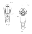
- the body At the front end 80 of the curved portion 64, at the cross-section C-C, the body has a width and height that are each about 21 ⁇ 4 inch (preferably 1.75 to 2.75 inches).
- Fig. 3 shows an imaginary circle 70 of 2% inch diameter on which the thumb T and index finger I lie.
- An average sized hand e.g. a distance of 6 inches between the tips of the thumbs and index fingers
- the body front portion 42 has a largely circular bottom, as viewed along the axis 60, has an upstanding ridge 72 at the top, and has a pair of gently concave grooves or recesses 74, 76 on opposite sides of the ridge.
- the rear body portion 44 is circular, with a diameter of about 1.7 inch. This shape, which includes a bend at the middle of the body length and a cable extending downward and rearward from the body rear end, makes it obvious to a person who is reaching for the connector to grasp it with the palm pad at the top, and to place his/her thumb in one of the grooves while his/her other fingers extend partially around the bottom portion of the body. As mentioned above, such grasping of the connector results in the person's palm depressing the palm pad when his grip tightens.
- Fig. 4 illustrates the left side of a connector 100 of another embodiment of the invention which is the same as that of Figs 1-3 , but with a longer rear portion 102.
- This enables the connector to be readily grasped with the index finger I and thumb T at the front end 82 ( Fig. 5 ) of the concavely curved body bottom portion 64 instead of at the rear 80.
- the palm pad 104 is longer to extend further rearward, so the connector can be readily grasped in the manner of Fig. 1 or Fig. 4 .
- the rear end 84, 106 of the palm pad lies within 21 ⁇ 4 inch of the rear of the body where the cable emerges at 110, to minimize the possibility of the palm pad pinching the heel of the person's hand. Pinching of the heel is very unlikely.
- the rear of the palm pad projects upward by about 1 ⁇ 4 inch from the body when the pad is not depressed.
- a person grasps the connector as shown in Figs. 1 or 4 moves it forward into the mating connector, or receiver 14, and relinquishes his/her grasp.
- the latch is automatically operated by spring force to hold the connector to the receiver.
- the person grasps the connector and in so doing depresses the palm pad to release the latch and allow the connector to be withdrawn from the receiver.
- the invention provides an electrical connector that can be grasped in a person's hand and inserted into a mating connector, which makes it obvious how the connector should be grasped and which automatically latches and unlatches the connector from the mating connector.
- the connector is especially useful for a vehicle battery charger, but is useful in other applications.
- a palm pad is mounted on the connector body, and lies on the top of the body, so the pad is depressed when a person grasps the connector in the manner of a handshake.
- the body has front, rear, and middle portions. The front portion extends along a primarily horizontal axis, and the rear portion extends along a rearward-downward axis that extends at a downward angle of about 45° from the horizontal.
- the body middle has a lower surface that is concavely curved about a lateral axis.
- the shape encourages a person to grasp the connector with his/her thumb extending partially about a top ridge and against the bottom of a gentle groove, and with the other fingers extending partially about the concave lower surface.
- the connector is usually grasped with the index finger at the front or rear end of the concavely curved lower surface.
Landscapes
- Engineering & Computer Science (AREA)
- Power Engineering (AREA)
- Transportation (AREA)
- Mechanical Engineering (AREA)
- Details Of Connecting Devices For Male And Female Coupling (AREA)
Applications Claiming Priority (1)
| Application Number | Priority Date | Filing Date | Title |
|---|---|---|---|
| US12/978,369 US8197277B1 (en) | 2010-12-23 | 2010-12-23 | Charger connector |
Publications (1)
| Publication Number | Publication Date |
|---|---|
| EP2469664A1 true EP2469664A1 (de) | 2012-06-27 |
Family
ID=45315567
Family Applications (1)
| Application Number | Title | Priority Date | Filing Date |
|---|---|---|---|
| EP11192039A Withdrawn EP2469664A1 (de) | 2010-12-23 | 2011-12-06 | Ladestecker |
Country Status (4)
| Country | Link |
|---|---|
| US (1) | US8197277B1 (de) |
| EP (1) | EP2469664A1 (de) |
| JP (1) | JP5301617B2 (de) |
| CN (1) | CN102570170B (de) |
Cited By (2)
| Publication number | Priority date | Publication date | Assignee | Title |
|---|---|---|---|---|
| EP3261194A1 (de) * | 2016-06-24 | 2017-12-27 | Gyrus ACMI, Inc. (D.B.A. Olympus Surgical Technologies America) | Stecker |
| USD837157S1 (en) | 2017-04-11 | 2019-01-01 | Gyrus Acmi, Inc. | Plug |
Families Citing this family (18)
| Publication number | Priority date | Publication date | Assignee | Title |
|---|---|---|---|---|
| JP5486397B2 (ja) * | 2010-05-12 | 2014-05-07 | 株式会社東海理化電機製作所 | 給電プラグロック装置 |
| JP5486398B2 (ja) * | 2010-05-12 | 2014-05-07 | 株式会社東海理化電機製作所 | 給電プラグロック装置 |
| JP5411059B2 (ja) * | 2010-05-18 | 2014-02-12 | 株式会社東海理化電機製作所 | 充電インレット装置 |
| JP2012080646A (ja) * | 2010-09-30 | 2012-04-19 | Tokai Rika Co Ltd | 給電プラグロック装置 |
| US20120126747A1 (en) * | 2010-11-19 | 2012-05-24 | Delphi Technologies, Inc. | Battery charger having non-contact electrical switch |
| US8647134B2 (en) * | 2012-03-26 | 2014-02-11 | GM Global Technology Operations LLC | Charge cord lock for electric vehicle |
| CN104412465A (zh) * | 2012-07-09 | 2015-03-11 | 日产自动车株式会社 | 电动车辆的充电端口装置 |
| JP6182324B2 (ja) * | 2013-02-20 | 2017-08-16 | 日本航空電子工業株式会社 | 電動車両用電力コネクタ |
| JP5690914B1 (ja) * | 2013-12-16 | 2015-03-25 | 株式会社フジクラ | 給電コネクタ |
| CN104882713B (zh) * | 2015-06-15 | 2017-03-08 | 南京康尼新能源汽车零部件有限公司 | 一种抓握式操作及整体式结构的电动汽车充电枪 |
| US20190267758A1 (en) * | 2016-11-30 | 2019-08-29 | Lg Innotek Co., Ltd. | Electricity charging plug device, electricity charging connection device, electricity charging device and electric vehicle |
| US10515742B1 (en) * | 2018-05-31 | 2019-12-24 | General Electric Company | Power cable and system for delivering electrical power |
| EP3771045A1 (de) * | 2019-07-25 | 2021-01-27 | ABB Schweiz AG | Ladeanordnung zum laden von elektrischen fahrzeugen |
| USD1051827S1 (en) * | 2022-12-20 | 2024-11-19 | Shenzhen Kule Youpin Technology Co., Ltd. | Charging adapter |
| USD1051826S1 (en) * | 2022-12-20 | 2024-11-19 | Shenzhen Kule Youpin Technology Co., Ltd | Charging adapter |
| USD1093311S1 (en) * | 2023-06-07 | 2025-09-16 | Dongguan LanXing Charging Technology Co., Ltd. | Charging adapter |
| USD1079618S1 (en) * | 2023-07-28 | 2025-06-17 | Guangdong Chongwei technology Co., LTD | Charging gun |
| USD1098006S1 (en) * | 2023-11-07 | 2025-10-14 | Juntao Hu | Electric vehicle charger plug |
Citations (4)
| Publication number | Priority date | Publication date | Assignee | Title |
|---|---|---|---|---|
| DE19509336A1 (de) * | 1994-03-17 | 1995-09-28 | Yazaki Corp | Einspeise-Steckverbindung |
| DE202008009929U1 (de) * | 2008-07-23 | 2009-12-10 | Rema Lipprandt Gmbh & Co. Kg | Ladesteckvorrichtung für Kraftfahrzeuge mit Elektroantrieb |
| US20100197171A1 (en) * | 2009-02-04 | 2010-08-05 | Yazaki Corporation | Connector |
| JP2010182461A (ja) * | 2009-02-03 | 2010-08-19 | Toyota Motor Corp | 充電用コネクタ |
Family Cites Families (21)
| Publication number | Priority date | Publication date | Assignee | Title |
|---|---|---|---|---|
| JP3042816B2 (ja) | 1992-12-18 | 2000-05-22 | 矢崎総業株式会社 | 給電コネクタ |
| US5429524A (en) | 1993-04-16 | 1995-07-04 | Sumitomo Wiring Systems, Ltd. | Coupling device of charging connector assembly for electric car |
| JP2929900B2 (ja) | 1993-06-22 | 1999-08-03 | 住友電装株式会社 | コネクタの接続端子 |
| JP3112226B2 (ja) | 1993-12-27 | 2000-11-27 | 矢崎総業株式会社 | 電気自動車用充電コネクタ |
| USD369782S (en) * | 1994-04-14 | 1996-05-14 | Yazaki Corporation | Connector shell for electric supplier for electric car |
| JP3292278B2 (ja) | 1995-12-06 | 2002-06-17 | 矢崎総業株式会社 | 電気自動車の充電用コネクタ |
| JP3449517B2 (ja) | 1996-10-04 | 2003-09-22 | 矢崎総業株式会社 | 電気自動車用充電コネクタ |
| US6371768B1 (en) | 1998-03-31 | 2002-04-16 | Daimlerchrysler Corporation | Universal charge port connector for electric vehicles |
| JP3731797B2 (ja) | 1999-11-08 | 2006-01-05 | 矢崎総業株式会社 | 給電コネクタ |
| JP3866052B2 (ja) | 2001-05-24 | 2007-01-10 | 矢崎総業株式会社 | 給電コネクタ |
| JP2002367729A (ja) * | 2001-06-08 | 2002-12-20 | Ryosei Electro-Circuit Systems Ltd | レバー式コネクタ |
| US6910911B2 (en) * | 2002-06-27 | 2005-06-28 | Vocollect, Inc. | Break-away electrical connector |
| AU2003901230A0 (en) * | 2003-03-18 | 2003-04-03 | Wharton, Geoffrey Mr | New generation of electrical plugs and socket systems |
| US8262403B2 (en) * | 2009-09-10 | 2012-09-11 | Vocollect, Inc. | Break-away electrical connector |
| US7963793B2 (en) * | 2009-09-24 | 2011-06-21 | Lear Corporation | Hybrid/electric vehicle charge handle latch mechanism |
| US8016607B2 (en) * | 2010-01-08 | 2011-09-13 | Lear Corporation | Connector assembly for electric vehicle charging |
| US8025526B1 (en) * | 2010-04-21 | 2011-09-27 | Coulomb Technologies, Inc. | Self powered electric vehicle charging connector locking system |
| CN101867122B (zh) * | 2010-04-23 | 2012-10-17 | 张家港友诚科技机电有限公司 | 充电接口的防拔结构 |
| US8196375B2 (en) * | 2010-05-27 | 2012-06-12 | Matrix Technologies Corporation | Handheld tube capper/decapper |
| US8075329B1 (en) * | 2010-06-08 | 2011-12-13 | Ford Global Technologies, Llc | Method and system for preventing disengagement between an electrical plug and a charge port on an electric vehicle |
| JP5197699B2 (ja) * | 2010-09-09 | 2013-05-15 | 住友電装株式会社 | 充電用コネクタ |
-
2010
- 2010-12-23 US US12/978,369 patent/US8197277B1/en active Active
-
2011
- 2011-06-21 CN CN201110166973.9A patent/CN102570170B/zh not_active Expired - Fee Related
- 2011-07-21 JP JP2011159560A patent/JP5301617B2/ja not_active Expired - Fee Related
- 2011-12-06 EP EP11192039A patent/EP2469664A1/de not_active Withdrawn
Patent Citations (4)
| Publication number | Priority date | Publication date | Assignee | Title |
|---|---|---|---|---|
| DE19509336A1 (de) * | 1994-03-17 | 1995-09-28 | Yazaki Corp | Einspeise-Steckverbindung |
| DE202008009929U1 (de) * | 2008-07-23 | 2009-12-10 | Rema Lipprandt Gmbh & Co. Kg | Ladesteckvorrichtung für Kraftfahrzeuge mit Elektroantrieb |
| JP2010182461A (ja) * | 2009-02-03 | 2010-08-19 | Toyota Motor Corp | 充電用コネクタ |
| US20100197171A1 (en) * | 2009-02-04 | 2010-08-05 | Yazaki Corporation | Connector |
Cited By (5)
| Publication number | Priority date | Publication date | Assignee | Title |
|---|---|---|---|---|
| EP3261194A1 (de) * | 2016-06-24 | 2017-12-27 | Gyrus ACMI, Inc. (D.B.A. Olympus Surgical Technologies America) | Stecker |
| US10658802B2 (en) | 2016-06-24 | 2020-05-19 | Gyrus Acmi, Inc. | Gravity plug and connector |
| US11283225B2 (en) | 2016-06-24 | 2022-03-22 | Gyrus Acmi, Inc. | Gravity plug and connector |
| US11688982B2 (en) | 2016-06-24 | 2023-06-27 | Gyrus Acmi, Inc. | Gravity plug and connector |
| USD837157S1 (en) | 2017-04-11 | 2019-01-01 | Gyrus Acmi, Inc. | Plug |
Also Published As
| Publication number | Publication date |
|---|---|
| JP2012134123A (ja) | 2012-07-12 |
| CN102570170B (zh) | 2014-12-24 |
| JP5301617B2 (ja) | 2013-09-25 |
| CN102570170A (zh) | 2012-07-11 |
| US20120164871A1 (en) | 2012-06-28 |
| US8197277B1 (en) | 2012-06-12 |
Similar Documents
| Publication | Publication Date | Title |
|---|---|---|
| EP2469664A1 (de) | Ladestecker | |
| JP5567739B2 (ja) | 電気プラグ | |
| US9130384B2 (en) | Smart phone and/or consumer electronics device charger system | |
| US6562509B1 (en) | Multi-use lead-acid power pack for use with a cordless power hand tool and other loads | |
| JP3066364U (ja) | 親子式安全プラグ | |
| US9966712B1 (en) | Battery plug-in device for material handling equipment | |
| US20130130532A1 (en) | Docking station for connector for electric vehicle charging station | |
| US20100192314A1 (en) | Handy cleaners | |
| JP4793515B2 (ja) | 電池パック及び電動工具 | |
| JP2007188717A (ja) | 電池パックの係止機構 | |
| US7746028B1 (en) | Headset charging cradle | |
| EP3309001A1 (de) | Steckbare batterievorrichtung für materialhandhabungsausrüstung | |
| CN101523688A (zh) | 电池充电器 | |
| CN201051571Y (zh) | 一种弹射式带套保护插头 | |
| EP1139540A1 (de) | Wechselstromlader | |
| US20200373701A1 (en) | Charger Safety Cover | |
| JP2007123082A (ja) | 電池パック | |
| US20190006791A1 (en) | Cable Strain Relief Device With Grip Member | |
| US20190081508A1 (en) | Inductive charging station for an electronic device | |
| JP5387865B2 (ja) | 電池パック | |
| CN217468614U (zh) | 一种新型控制盒用电池安装结构 | |
| US20080196244A1 (en) | Electrical outlet cover remover | |
| CN215116597U (zh) | 一种带放电保护的电缆故障定位仪 | |
| CN223771386U (zh) | 充电枪和充电设备 | |
| CN220680861U (zh) | 一种具有多种充电方式电池的电动剪刀 |
Legal Events
| Date | Code | Title | Description |
|---|---|---|---|
| AK | Designated contracting states |
Kind code of ref document: A1 Designated state(s): AL AT BE BG CH CY CZ DE DK EE ES FI FR GB GR HR HU IE IS IT LI LT LU LV MC MK MT NL NO PL PT RO RS SE SI SK SM TR |
|
| AX | Request for extension of the european patent |
Extension state: BA ME |
|
| PUAI | Public reference made under article 153(3) epc to a published international application that has entered the european phase |
Free format text: ORIGINAL CODE: 0009012 |
|
| 17P | Request for examination filed |
Effective date: 20120711 |
|
| RAP1 | Party data changed (applicant data changed or rights of an application transferred) |
Owner name: ITT MANUFACTURING ENTERPRISES LLC |
|
| 17Q | First examination report despatched |
Effective date: 20130409 |
|
| GRAP | Despatch of communication of intention to grant a patent |
Free format text: ORIGINAL CODE: EPIDOSNIGR1 |
|
| INTG | Intention to grant announced |
Effective date: 20171018 |
|
| STAA | Information on the status of an ep patent application or granted ep patent |
Free format text: STATUS: THE APPLICATION IS DEEMED TO BE WITHDRAWN |
|
| 18D | Application deemed to be withdrawn |
Effective date: 20180301 |