EP2471439B1 - Empfängersystem - Google Patents
Empfängersystem Download PDFInfo
- Publication number
- EP2471439B1 EP2471439B1 EP10811611.2A EP10811611A EP2471439B1 EP 2471439 B1 EP2471439 B1 EP 2471439B1 EP 10811611 A EP10811611 A EP 10811611A EP 2471439 B1 EP2471439 B1 EP 2471439B1
- Authority
- EP
- European Patent Office
- Prior art keywords
- wireless relay
- receiving
- unit
- transmitting
- relay devices
- Prior art date
- Legal status (The legal status is an assumption and is not a legal conclusion. Google has not performed a legal analysis and makes no representation as to the accuracy of the status listed.)
- Not-in-force
Links
- 238000001727 in vivo Methods 0.000 claims description 65
- 239000002775 capsule Substances 0.000 claims description 45
- 230000005684 electric field Effects 0.000 claims description 16
- 230000005540 biological transmission Effects 0.000 claims description 8
- 238000000034 method Methods 0.000 description 13
- 230000008569 process Effects 0.000 description 13
- 238000010586 diagram Methods 0.000 description 7
- 210000001835 viscera Anatomy 0.000 description 6
- 238000003384 imaging method Methods 0.000 description 4
- 239000000758 substrate Substances 0.000 description 3
- 230000008859 change Effects 0.000 description 2
- 238000004891 communication Methods 0.000 description 2
- 230000033001 locomotion Effects 0.000 description 2
- 238000012986 modification Methods 0.000 description 2
- 230000004048 modification Effects 0.000 description 2
- 230000002572 peristaltic effect Effects 0.000 description 2
- 230000001144 postural effect Effects 0.000 description 2
- 238000004590 computer program Methods 0.000 description 1
- 238000003745 diagnosis Methods 0.000 description 1
- 230000000694 effects Effects 0.000 description 1
- 238000007519 figuring Methods 0.000 description 1
- 230000004044 response Effects 0.000 description 1
- 210000000813 small intestine Anatomy 0.000 description 1
- 210000002784 stomach Anatomy 0.000 description 1
- 230000001360 synchronised effect Effects 0.000 description 1
Images




Classifications
-
- A—HUMAN NECESSITIES
- A61—MEDICAL OR VETERINARY SCIENCE; HYGIENE
- A61B—DIAGNOSIS; SURGERY; IDENTIFICATION
- A61B1/00—Instruments for performing medical examinations of the interior of cavities or tubes of the body by visual or photographical inspection, e.g. endoscopes; Illuminating arrangements therefor
- A61B1/04—Instruments for performing medical examinations of the interior of cavities or tubes of the body by visual or photographical inspection, e.g. endoscopes; Illuminating arrangements therefor combined with photographic or television appliances
- A61B1/041—Capsule endoscopes for imaging
-
- A—HUMAN NECESSITIES
- A61—MEDICAL OR VETERINARY SCIENCE; HYGIENE
- A61B—DIAGNOSIS; SURGERY; IDENTIFICATION
- A61B1/00—Instruments for performing medical examinations of the interior of cavities or tubes of the body by visual or photographical inspection, e.g. endoscopes; Illuminating arrangements therefor
- A61B1/00002—Operational features of endoscopes
- A61B1/00011—Operational features of endoscopes characterised by signal transmission
- A61B1/00016—Operational features of endoscopes characterised by signal transmission using wireless means
-
- A—HUMAN NECESSITIES
- A61—MEDICAL OR VETERINARY SCIENCE; HYGIENE
- A61B—DIAGNOSIS; SURGERY; IDENTIFICATION
- A61B1/00—Instruments for performing medical examinations of the interior of cavities or tubes of the body by visual or photographical inspection, e.g. endoscopes; Illuminating arrangements therefor
- A61B1/00002—Operational features of endoscopes
- A61B1/00025—Operational features of endoscopes characterised by power management
- A61B1/00036—Means for power saving, e.g. sleeping mode
-
- A—HUMAN NECESSITIES
- A61—MEDICAL OR VETERINARY SCIENCE; HYGIENE
- A61B—DIAGNOSIS; SURGERY; IDENTIFICATION
- A61B5/00—Measuring for diagnostic purposes; Identification of persons
- A61B5/07—Endoradiosondes
- A61B5/073—Intestinal transmitters
Definitions
- the present invention relates to a receiver system for transmitting in-vivo information including in-vivo images transmitted from a capsule endoscope being located in a subject to a receiving device being outside of the living body via a plurality of wireless relay devices that are disposed on the outer surface of the living body.
- a capsule endoscope which has a capsule-shaped casing enclosing therein an imaging function and a wireless communication function, has been introduced in recent years as an in-vivo image obtaining device for obtaining in-vivo images.
- a capsule endoscope is carried through internal organs such as stomach or small intestine by peristaltic motions and the like while capturing a series of in-vivo images of a subject, e.g., a patient, at a predetermined interval during a period from when the capsule endoscope is orally swallowed by the subject for the purpose of observation (examination) to when the endoscope is naturally excreted from the subject.
- the capsule endoscope sequentially transmits the in-vivo images thus captured (obtained) wirelessly.
- a receiving device carried by the subject sequentially receives the in-vivo images transmitted by the capsule endoscope wirelessly.
- the receiving device includes a recording medium mounted on the receiving device in a removable manner, and stores a set of in-vivo images received from the capsule endoscope being located in the subject in the recording medium.
- the recording medium with the set of in-vivo images of the subject recorded therein is then removed from the receiving device, and mounted onto an image display device.
- the image display device obtains the set of in-vivo images of the subject via the storage medium, and displays the set of in-vivo images of the subject onto a display.
- an in-vivo image acquiring system including the capsule endoscope, the receiving device, and the image display device
- a user such as a doctor or a nurse causes the set of in-vivo images captured by the capsule endoscope to be displayed onto the image display device to observe (examine) the interior of the internal organs of the subject through the set of in-vivo images.
- Document EP 2 011 430 A1 discloses a receiving system including an antenna unit and an external unit, and the antenna unit and the external unit are wirelessly connected, the antenna unit having a receiving antenna that receives a radio signal transmitted at a frequency of a megahertz range from a capsule endoscope, a cable, and a main body part which is provided with a frequency converter that converts the signal received by the receiving antenna into a signal of a gigahertz frequency and a transmitting antenna that transmits the frequency signal converted by the frequency converter as a radio signal, and the external unit having a receiving antenna that receives the radio signal of the gigahertz range frequency transmitted from the transmitting antenna, a receiver that receives and demodulates the radio signal received by the receiving antenna, and a signal processor that generates image information.
- the above-described in-vivo image acquiring system uses a cable to connect, in a wired manner, between an antenna disposed on a body surface of a subject and the receiving device.
- a plurality of the antennas is disposed on the body surface, and the antenna having high received electrical field intensity is selected from among the disposed plural antennas to receive in-vivo images.
- the present invention has been made in view of the foregoing, and an object of the present invention is to provide a receiver system in which antennas can be easily attached onto the body surface without losing the receiving function of the antennas and the freedom for the living body can be improved.
- control unit transmits a received electrical field intensity that is received from the capsule endoscope via the interior side receiving unit to the receiving device via the exterior side transmitting unit, and the control unit transmits, when receiving an instruction for transmitting the in-vivo information from the receiving device, the in-vivo information received by the interior side receiving unit to the receiving device via the exterior side transmitting unit.
- each of the wireless relay devices and the receiving device have an anti-collision function.
- each of the wireless relay devices further includes a power converting and accumulating unit that converts a signal received via the exterior side receiving unit at the second frequency to power and accumulates therein the power.
- each of the wireless relay devices further includes a battery for supplying power.
- the control unit performs intermittent reception control in which the interior side receiving unit is started when a control signal is received from the receiving device and the interior side receiving unit is stopped after a predetermined time period when no instruction for transmitting the in-vivo information is received, and the interior side receiving unit is stopped after the in-vivo information is transmitted when an instruction for transmitting the in-vivo information is received.
- each of the wireless relay devices includes a plate-like dielectric member in which a receiving antenna for receiving the information at the first frequency is formed at one surface of the plate-like dielectric member and a transmitting and receiving antenna for transmitting and receiving the information at the second frequency is formed the other surface of the plate-like dielectric member, and the one surface is arranged to face a surface of the subject.
- the interior side receiving unit includes the receiving antenna that is an interior side receiving antenna
- the exterior side transmitting unit and the exterior side receiving unit include the transmitting and receiving antenna that is a shared transmitting and receiving antenna
- the interior side receiving unit excluding the receiving antenna, the exterior side transmitting unit and the exterior side receiving unit excluding the transmitting and receiving antenna, and the control unit are formed as a single chip and are arranged on the plate-like dielectric member or in the plate-like dielectric member.
- the interior side receiving unit of each wireless relay device receives in-vivo information transmitted by the capsule endoscope at a first frequency
- the exterior side transmitting unit transmits the in-vivo information at a second frequency
- the exterior side receiving unit receives a control signal transmitted by the receiving device at the second frequency
- the control unit controls transmissions and receptions by the interior side receiving unit and the exterior side transmitting unit based on the control signal.
- FIG. 1 is a schematic showing a configuration of an in-vivo image acquiring system to which a receiver system according to a first embodiment of the present invention is applied.
- the in-vivo image acquiring system includes a capsule endoscope 2 that captures in-vivo images of a subject 1, a plurality of wireless relay devices 3 (3a to 3h) that wirelessly relay in-vivo information including the in-vivo images transmitted by the capsule endoscope 2 introduced into the subject 1, a receiving device 4 that receives the in-vivo information wirelessly relayed by each of the wireless relay devices 3 and controls each of the wireless relay devices 3, an image display device 5 that processes and displays thereon the in-vivo images of the subject 1 received by the receiving device 4, and a portable recording medium 6 for transmitting and receiving data between the receiving device 4 and the image display device 5.
- the capsule endoscope 2 is introduced into the subject 1, and captures in-vivo images of the subject 1. After being orally swallowed by the subject 1, the capsule endoscope 2 is carried through internal organs by peristaltic motions and the like of the internal organs, while capturing a series of in-vivo images of the subject 1. Every time an in-vivo image of the subject 1 is captured, the capsule endoscope 2 wirelessly transmits an image signal containing the in-vivo image thus captured to the external receiving device 4 via the wireless relay devices 3. Upon doing so, the capsule endoscope 2 transmits each of the in-vivo images of the subject 1 at a time interval corresponding to a unique function of the capsule endoscope 2. For example, the capsule endoscope 2 captures and wirelessly transmits one in-vivo image every two seconds.
- Each of the wireless relay devices 3 is disposed on the body surface of the subject 1 in a distributed manner, e.g., along the path where the capsule endoscope 2 introduced into the internal organs of the subject 1 is carried, and is wirelessly connected to the receiving device 4.
- the wireless relay device 3 captures the image signals that are sequentially wirelessly transmitted from the capsule endoscope 2 being located in the subject 1, and sequentially relays the captured image signals wirelessly to the receiving device 4.
- the wireless relay devices 3 may also be disposed in a distributed manner on a jacket worn by the subject 1, for example.
- One or more wireless relay devices 3 need to be disposed, and the number of the devices disposed is not limited to eight.
- the receiving device 4 receives the in-vivo images of the subject 1 captured by the capsule endoscope 2 via one of the wireless relay devices 3 with the highest received electrical field intensity, and accumulates therein the received set of in-vivo images.
- the receiving device 4 includes the portable recording medium 6 attached to the receiving device 4 in a removable manner, and stores the set of in-vivo images of the subject 1 obtained from the capsule endoscope 2 in the portable recording medium 6.
- the image display device 5 is realized as a workstation and the like that obtains various types of data such as a set of in-vivo images of the subject 1 via the portable recording medium 6, and displays the various types of data thus obtained onto a display.
- a physician or a nurse makes a diagnosis on the subject 1 by observing each of the in-vivo images of the subject 1 displayed on the image display device 5.
- the portable recording medium 6 is a portable recording medium, and used for transmitting and receiving data between the receiving device 4 and the image display device 5.
- the portable recording medium 6 has a structure enabled to be attached to and removed from the receiving device 4 and the image display device 5, and to output and to record data when attached to the both.
- FIG. 2 is a cross-sectional view showing a structure of the capsule endoscope 2.
- the capsule endoscope 2 includes, inside a capsule-shaped casing 10 formed in a size for allowing easy introduction into the subject 1, a plurality of illuminating units 11 for illuminating the interior of the subject 1, an imaging unit 12 that captures in-vivo images of the interior of the internal organs of the subject 1 illuminated by the illuminating units 11, and a wireless unit 13a and an antenna 13b for wirelessly transmitting the in-vivo images captured by the imaging unit 12 to the exterior.
- the capsule endoscope 2 also includes a control unit 15 that controls the illuminating units 11, the imaging unit 12, and the wireless unit 13a, and batteries 14a and a power circuit 14b for supplying power to each of these components included in the capsule endoscope 2.
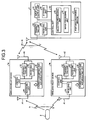
- FIG. 3 is a block diagram showing a configuration of the receiver system according to the first embodiment of the present invention.
- this receiver system includes the capsule endoscope 2, the receiving device 4, and the wireless relay devices 3.
- the wireless relay devices 3 receive in-vivo information including in-vivo images transmitted wirelessly by the capsule endoscope 2 at a frequency f1, and performs wireless transmissions and receptions with the receiving device 4 at a frequency f2 and transmits the in-vivo information received from the capsule endoscope 2 to the receiving device 4 wirelessly.
- the wireless frequency f1 between the capsule endoscope 2 and the wireless relay devices 3 and the wireless frequency f2 between the wireless relay devices 3 and the receiving device 4 are made different to prevent crosstalk.
- Each of the wireless relay devices 3 includes a receiving antenna A1 and a receiving unit R1 signals at the frequency f1 transmitted by the capsule endoscope 2 wirelessly.
- Each of the wireless relay devices 3 also includes an antenna A2, a transmitting unit S2, and a receiving unit R2 for transmitting and receiving signals to and from the receiving device 4 at the frequency f2.
- Each of the wireless relay devices 3 also includes a control unit C that performs control of the entire wireless relay device, such as transmission and reception control and power control.
- Each of the wireless relay devices 3 further includes a power converting and accumulating unit 20 that rectifies, power-converts, and accumulates alternating wireless signals received via the antenna A2 and the receiving unit R2. In other words, the wireless relay devices 3 receive wireless waves at the frequency f2 transmitted by the receiving device 4 and convert the power thereof to use the power thus converted as the power source of the wireless relay devices 3. The supply of this accumulated power is controlled under the control of the control unit C.
- the receiving device 4 includes a transmitting unit S4 that performs transmissions to the wireless relay devices 3 using wireless signals at the frequency f2, a receiving unit R4 that receives wireless signals at the frequency f2 from the wireless relay devices 3, an input-and-output unit 41 that inputs and outputs various types of information, a storage unit 42 that stores therein various computer programs and data, the removable portable recording medium 6, and a control unit MC that controls each of these components.
- the control unit MC includes a selection processing unit 43 that selects a wireless relay device via which the wireless signals from the capsule endoscope 2 are received at the highest electrical field intensity as a wireless relay device for transferring images, and an image processing unit 44 that applies image processing to received image information.
- the receiving device 4 transmits a polling signal to each of the wireless relay devices 3 (3a to 3h) (Step S201).
- This polling signal also functions to supply power.
- a wireless signal transmitted by the receiving device 4 functions as a signal for supplying power.
- each of the wireless relay devices 3 determines if the power is supplied upon receiving the polling signal and if the polling signal is received (Step S101), and waits to receive the next polling signal (NO at Step 101).
- the corresponding wireless relay device 3 sets up its own timeslot with the receiving device 4 (Steps S102 and S202). In other words, by allocating a timeslot, the wireless relay device 3 performs an anti-collision process for preventing collisions of communications between the receiving device 4 and each of the wireless relay devices 3. In this anti-collision process, a random number, for example, for deciding the control priority is generated and a timeslot is allocated to each of the wireless relay devices.
- the wireless relay device 3 then turns ON and starts the receiving unit R1 for receiving the wireless signals from the capsule endoscope 2 (Step S103).
- the receiving device 4 sends out a polling signal again to each of the wireless relay devices 3 after being allocated with the timeslot (Step S203).
- the capsule endoscope 2 is transmitting the in-vivo information as a burst signal.
- the wireless relay device 3 determines if the polling signal from the receiving device 4 is received (Step S104), and waits until the next polling signal is received (NO at Step S104). If the wireless relay device 3 receives the polling signal (YES at Step S104), the wireless relay device 3 measures the electrical field intensity during the period in which the idle section E1, illustrated in the in-vivo information format depicted in FIG. 5 , is being transmitted (Step S105). The wireless relay device 3 then transmits the measured received electrical field intensity to the receiving device 4 in the timeslot allocated thereto (Step S106).
- the idle section E1 includes a synchronization signal for measuring the received electrical field intensity. Of course, a signal for the received electrical field intensity may be included in the idle section E1.
- An image information section E2 represents the body of information, and contains the image information itself.
- the receiving device 4 Upon receiving the received electrical field intensity (Step S204), the receiving device 4 transmits a selecting control signal for instructing the transmission of the in-vivo information (image information) to the wireless relay device 3 with the highest received electrical field intensity, amongst those from which the received electrical field intensities are received (Step S205).
- the wireless relay device 3 determines if the selecting control signal is received (Step S107), and if the selecting control signal is not received (NO at Step S107), goes onto Step S104, further determines if the next polling signal is received, and waits until the next polling signal is received (NO at Step S104). On the contrary, if the selecting control signal is received (YES at Step S107), the wireless relay device 3 further determines if the selecting control signal is addressed to itself (Step S108). If the selecting control signal is not addressed to itself (NO at Step 108), the wireless relay device goes onto Step S104, determines if the next polling signal is received, and waits until the next polling signal is received (NO at Step S104).
- the wireless relay device 3 receives the image information, and transmits and relays the information to the receiving device 4 (Step S109). After completing transmitting and relaying the image information, the wireless relay device 3 determines if the process is completed (Step S110). As long as the process is not completed (NO at Step S110), the wireless relay device 3 goes onto Step S104, and waits until the next polling signal is received (NO at Step S104). On the other side, the receiving device 4 receives the transmitted and relayed image information (Step S206). As long as no completion instruction is received (NO at Step S207), the receiving device 4 goes onto Step S203, and transmits the next polling signal.
- the polling signals of the receiving device are used in instructing the wireless relay devices 3 to wirelessly relay the image information.
- the reception timing of the image information which is a burst signal, and the transmission timing of the polling signal need to be synchronized.
- the image information is transmitted at a predetermined interval, e.g., every two seconds, the receiving device 4 controls the timing for transmitting the polling signals by figuring out the predetermined interval to achieve the synchronization. In other words, the reception timing of the polling signals will arrive immediately before receiving the image signal to be received.
- each of the wireless relay devices 3 is formed in a flat plate like shape, with the antenna A1, the antenna A2, the control unit C, and the power converting and accumulating unit 20 formed integrally to a flexible substrate 50, as illustrated in FIGS. 6 and 7.
- FIG. 6 shows the wireless relay device viewed from the rear side, that is, from the interior side of the body, and the antenna A1 is formed on the rear side.
- the antenna A2 is formed on the front side, that is on the exterior side of the body, as illustrated in FIG. 7 . Because the antenna A2 needs to receive power supply efficiently, the antenna A2 is formed as a wound spiral coil-like antenna.
- the antenna A1 on the interior side of the body is exposed because the antenna properties can be improved by bringing the antenna into direct contact with the body surface.
- the wireless relay devices 3 are used to wirelessly relay the image information transmitted by the capsule endoscope 2 to the receiving device 4, the antennas (wireless relay devices) can be applied onto the body surface freely without being restricted by the length of the antenna cables, and therefore, can be handled more easily without losing the receiving function of the antennas. Furthermore, because the receiving device 4 is not limited by the presence of the cable and is not necessarily attached to the body surface, a postural change and the like can be made more easily, whereby the freedom for the living body can be improved. Furthermore, unlike the conventional antennas, because the wireless relay devices do not need to be used repeatedly and can be disposed after use, sanitation can be controlled more easily.
- wireless relay devices receive power supply by means of wireless waves in the first embodiment, power is supplied using a battery in the second embodiment.
- FIG. 8 is a block diagram showing a configuration of a receiver system according to the second embodiment of the present invention.
- the receiver system includes a battery 60 such as a button cell instead of the power converting and accumulating unit 20 according to the first embodiment.
- the receiver system also includes a control unit CC instead of the control unit C.
- This control unit CC controls to cause the receiving unit R1 to perform receptions intermittently, that is, performs a control process for starting the receiving unit R1 intermittently so as to reduce the battery consumption.
- Other components are the same as those according to the first embodiment, and the same structural components are given the same reference numerals.
- Step S104 the receiving unit R1 is caused to start (Step S104a), and if the selecting control signal is not addressed to itself at Step S108 (NO at Step S108), the receiving unit R1 is turned OFF after the end of the polling signal (Step S108a).
- Step S104a the polling signal is received at Step S104
- Step S108a the selecting control signal is not addressed to itself at Step S108
- Step S108a the receiving unit R1 is turned OFF after the end of the polling signal.
- Other steps are the same as those in the sequence illustrated in FIG. 4 .
- FIG. 10 illustrates a case in which a particular wireless relay device 3 is not selected by the selecting control signal.
- the polling signal FIG. 10(a)
- an ON signal is kept transmitted for the period from the timing t1 to the timing t4.
- the selecting control signal is not addressed to the specific device ( FIG. 10(b) )
- the receiving unit R1 rises at the timing t2, which is immediately after the timing t1, as illustrated in FIG. 10(c) .
- the receiving unit R1 is then turned OFF at the timing t5, which is immediately after the timing t4 at which the polling signal ends. In this manner, the power consumed by the receiving unit R1 in the wireless relay devices not relaying the image information wirelessly is reduced.
- FIG. 11 shows a case where the specific wireless relay device 3 is selected by the selecting control signal.
- the polling signal illustrated in FIG. 11(a) is the same as the polling signal illustrated in 10(a) .
- the specific device is selected at the timing t3 by way of transmissions of the received electrical field intensity.
- the image information is wirelessly transmitted to the receiving device 4 during the period selected by the selecting control signal. Subsequently, when wireless transferring of the image information is completed, the selecting control signal is turned OFF at the timing t6, and the power of the receiving unit R1 is turned OFF immediately thereafter, whereby power consumption is reduced.
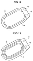
- each of the wireless relay devices 3 is formed in a flat plate like shape, with the antenna A1, the antenna A2, the control unit CC, and the battery 60 formed integrally to a flexible substrate 50, as illustrated in FIGS. 12 and 13 .
- Other components are the same as those in the structure illustrated in FIGS. 6 and 7 .
- the antenna A2 does not need to receive the power, the antenna A2 is not necessarily a long coil-like antenna. Rather, a small antenna can be realized. In other words, when the efficiency of the power reception is considered, the wireless frequency f1 needs to be low. However, without considering the efficiency of the power reception, an antenna for a high wireless frequency may be used. As a consequence, a small antenna can be used.
- the shape of the antenna can be designed freely.
- the wireless relay devices 3 are used to wirelessly relay the image information transmitted by the capsule endoscope 2 to the receiving device 4 in the same manner as in the first embodiment, the antennas (wireless relay devices) can be applied onto a body surface freely without being restricted by the length of the antenna cable, and therefore, can be handled more easily without losing the receiving function of the antennas. Furthermore, because the receiving device 4 is not limited by the presence of the cable and is not necessarily attached to the body surface, a postural change and the like can be made more easily, whereby the freedom for the living body can be improved. Furthermore, unlike the conventional antennas, because the wireless relay devices do not need to be used repeatedly and can be disposed after use, sanitation can be controlled more easily. Furthermore, while a battery is used as the source of the power supply, because the receiving unit R1 is started intermittently, power consumption can be reduced, and a system being feasible for practical applications can be realized.
Landscapes
- Life Sciences & Earth Sciences (AREA)
- Health & Medical Sciences (AREA)
- Surgery (AREA)
- Engineering & Computer Science (AREA)
- Biophysics (AREA)
- Public Health (AREA)
- Veterinary Medicine (AREA)
- Physics & Mathematics (AREA)
- Pathology (AREA)
- General Health & Medical Sciences (AREA)
- Animal Behavior & Ethology (AREA)
- Biomedical Technology (AREA)
- Heart & Thoracic Surgery (AREA)
- Medical Informatics (AREA)
- Molecular Biology (AREA)
- Radiology & Medical Imaging (AREA)
- Optics & Photonics (AREA)
- Nuclear Medicine, Radiotherapy & Molecular Imaging (AREA)
- Computer Networks & Wireless Communication (AREA)
- Endoscopes (AREA)
- Closed-Circuit Television Systems (AREA)
Claims (7)
- Empfängersystem, das umfasst:ein Kapselendoskop (2), das dazu eingerichtet ist, in ein Subjekt eingeführt zu werden und ein in-vivo Informationssignal einschließlich eines in-vivo Bilds zu senden,gekennzeichnet durcheine Mehrzahl von drahtlosen Relaiseinrichtungen (3), die auf einer Außenfläche des Subjekts angeordnet sind, dazu eingerichtet sind, das von dem Kapselendoskop (2) gesendete in-vivo Informationssignal zu empfangen, und dazu in der Lage sind, das in-vivo Informationssignal und/oder ein empfangenes elektrisches Feldintensitätssignal, das unter Verwendung des in-vivo Informationssignals gemessen wird, zu senden; undeine Empfangseinrichtung (4), die außerhalb des Subjekts angeordnet ist und dazu eingerichtet ist, das von den drahtlosen Relaiseinrichtungen (3) gesendete in-vivo Informationssignal zu empfangen, wobeijede der drahtlosen Relaiseinrichtungen (3) umfassteine Innenseiten-Empfangseinheit (R1), die dazu eingerichtet ist, das von dem Kapselendoskop (2) bei einer ersten Frequenz gesendete in-vivo Informationssignal zu empfangen;eine Außenseiten-Sendeeinheit (S2), die dazu eingerichtet ist, das in-vivo Informationssignal bei einer zweiten Frequenz zu senden;eine Außenseiten-Empfangseinheit (R2), die dazu eingerichtet ist, ein von der Empfangseinrichtung (4) bei der zweiten Frequenz gesendete Steuersignal zu empfangen; undeine Steuereinheit (C), die dazu eingerichtet ist, Sendevorgänge und Empfangsvorgänge der Innenseiten-Empfangseinheit (R1) und der Außenseiten-Sendeeinheit (S2) auf der Basis des Steuersignals zu steuern, wobeidie Empfangseinrichtung (4) dazu eingerichtet ist, an jede der drahtlosen Relaiseinrichtungen (3) ein Sendeabrufsignal zu senden,wobei jede der drahtlosen Relaiseinrichtungen (3) dazu eingerichtet ist, das empfangene elektrische Feldintensitätssignal an die Empfangseinrichtung (4) zu senden, wenn sie das Sendeabrufsignal empfängt,wobei die Empfangseinrichtung (4) dazu eingerichtet ist, auf der Basis eines jeden empfangenen elektrischen Feldintensitätssignals eine gewünschte drahtlose Relaiseinrichtung (3) aus den drahtlosen Relaiseinrichtungen (3) auszuwählen und ein Auswahlsignal an die ausgewählte drahtlose Relaiseinrichtung (3) zu senden,wobei die Steuereinheit (C) in jeder der drahtlosen Relaiseinrichtungen (3) dazu eingerichtet ist, beim Empfang des Auswahlsignals von der Empfangseinrichtung (4) zu bestimmen, ob das Auswahlsignal an die drahtlose Relaiseinrichtung (3) selbst adressiert ist, undwobei die Steuereinheit (C) dazu eingerichtet ist, das von der Innenseiten-Empfangseinheit (R1) empfangene in-vivo Informationssignal über die Außenseiten-Sendeeinheit (S2) an die Empfangseinrichtung (4) zu senden, wenn bestimmt wird, dass das Auswahlsignal an die drahtlose Relaiseinrichtung (3) selbst adressiert ist.
- Empfängersystem nach Anspruch 1, bei dem jede der drahtlosen Relaiseinrichtungen (3) und die Empfangseinrichtung (4) eine Anti-Kollisionsfunktion haben.
- Empfängersystem nach Anspruch 1, bei dem jede der drahtlosen Relaiseinrichtungen (3) ferner eine Energiewandler- und Speichereinheit (20) umfasst, die dazu eingerichtet ist, ein Signal, das über die Außenseiten-Empfangseinheit (R2) bei der zweiten Frequenz empfangen wird, in Energie umzuwandeln und darin die Energie zu speichern.
- Empfängersystem nach Anspruch 1, bei dem jede der drahtlosen Relaiseinrichtungen (3) ferner eine Batterie (60) zum Zuführen von Energie umfasst.
- Empfängersystem nach Anspruch 1, bei dem die Steuereinheit (C) dazu eingerichtet ist, eine intermittierende Empfangssteuerung durchzuführen, bei der die Innenseiten-Empfangseinheit (R1) gestartet wird, wenn das Auswahlsignal von der Empfangseinrichtung (4) empfangen wird, und die Innenseiten-Empfangseinheit (R1) nach einer vorbestimmten Zeitspanne gestoppt wird, wenn kein Befehl zum Senden des in-vivo Informationssignal zu empfangen wird, und die Innenseiten-Empfangseinheit (R1) gestoppt wird, nachdem das in-vivo Informationssignal gesendet worden ist, wenn ein Befehl zum Senden des in-vivo Informationssignals empfangen wird.
- Empfängersystem nach Anspruch 1, bei dem
jede der drahtlosen Relaiseinrichtungen (3) ein plattenartiges dielektrisches Element umfasst, in dem eine Empfangsantenne zum Empfangen der Information bei der ersten Frequenz an einer Oberfläche des plattenartigen dielektrischen Elements ausgebildet ist, und eine Sende- und Empfangsantenne zum Senden und Empfangen der Information bei der zweiten Frequenz an der anderen Oberfläche des plattenartigen dielektrischen Elements ausgebildet ist, und die eine Oberfläche so angeordnet ist, dass sie einer Oberfläche des Subjekts zugewandt ist. - Empfängersystem nach Anspruch 6, bei dem
die Innenseiten-Empfangseinheit (R1) die Empfangsantenne umfasst, die eine Innenseiten-Empfangsantenne ist,
die Außenseiten-Sendeeinheit (S2) und die Außenseiten-Empfangseinheit (R2) die Sende- und Empfangsantenne umfassen, die eine geteilte Sende- und Empfangsantenne ist, und
die Innenseiten-Empfangseinheit (R1) mit Ausnahme der Empfangsantenne, die Außenseiten-Sendeeinheit (S2) und die Außenseiten-Empfangseinheit (R2) mit Ausnahme der Sende- und Empfangsantenne und die Steuereinheit (C) als ein einziger Chip ausgebildet sind und auf dem plattenartigen dielektrischen Element oder in dem plattenartigen dielektrischen Element angeordnet sind.
Applications Claiming Priority (2)
| Application Number | Priority Date | Filing Date | Title |
|---|---|---|---|
| JP2009198606 | 2009-08-28 | ||
| PCT/JP2010/061409 WO2011024560A1 (ja) | 2009-08-28 | 2010-07-05 | 受信システム |
Publications (3)
| Publication Number | Publication Date |
|---|---|
| EP2471439A1 EP2471439A1 (de) | 2012-07-04 |
| EP2471439A4 EP2471439A4 (de) | 2013-05-01 |
| EP2471439B1 true EP2471439B1 (de) | 2016-10-19 |
Family
ID=43627671
Family Applications (1)
| Application Number | Title | Priority Date | Filing Date |
|---|---|---|---|
| EP10811611.2A Not-in-force EP2471439B1 (de) | 2009-08-28 | 2010-07-05 | Empfängersystem |
Country Status (5)
| Country | Link |
|---|---|
| US (1) | US8786691B2 (de) |
| EP (1) | EP2471439B1 (de) |
| JP (1) | JP5006474B2 (de) |
| CN (1) | CN102469928B (de) |
| WO (1) | WO2011024560A1 (de) |
Families Citing this family (28)
| Publication number | Priority date | Publication date | Assignee | Title |
|---|---|---|---|---|
| US8956287B2 (en) | 2006-05-02 | 2015-02-17 | Proteus Digital Health, Inc. | Patient customized therapeutic regimens |
| SG175681A1 (en) | 2006-10-25 | 2011-11-28 | Proteus Biomedical Inc | Controlled activation ingestible identifier |
| EP3785599B1 (de) | 2007-02-01 | 2022-08-03 | Otsuka Pharmaceutical Co., Ltd. | Systeme mit einnehmbaren ereignismarkern |
| WO2008101107A1 (en) | 2007-02-14 | 2008-08-21 | Proteus Biomedical, Inc. | In-body power source having high surface area electrode |
| US8540632B2 (en) | 2007-05-24 | 2013-09-24 | Proteus Digital Health, Inc. | Low profile antenna for in body device |
| EP2313002B1 (de) | 2008-07-08 | 2018-08-29 | Proteus Digital Health, Inc. | Datengrundlage für einnehmbare ereignismarker |
| JP2012514799A (ja) | 2009-01-06 | 2012-06-28 | プロテウス バイオメディカル インコーポレイテッド | 摂取に関連するバイオフィードバックおよび個別薬物療法の方法およびシステム |
| JP5006474B2 (ja) * | 2009-08-28 | 2012-08-22 | オリンパスメディカルシステムズ株式会社 | 受信システム |
| TWI517050B (zh) | 2009-11-04 | 2016-01-11 | 普羅托斯數位健康公司 | 供應鏈管理之系統 |
| TWI557672B (zh) | 2010-05-19 | 2016-11-11 | 波提亞斯數位康健公司 | 用於從製造商跟蹤藥物直到患者之電腦系統及電腦實施之方法、用於確認將藥物給予患者的設備及方法、患者介面裝置 |
| WO2015112603A1 (en) | 2014-01-21 | 2015-07-30 | Proteus Digital Health, Inc. | Masticable ingestible product and communication system therefor |
| KR101898964B1 (ko) * | 2011-07-21 | 2018-09-14 | 프로테우스 디지털 헬스, 인코포레이티드 | 모바일 통신 장치, 시스템, 및 방법 |
| JP5498630B1 (ja) * | 2012-06-08 | 2014-05-21 | オリンパスメディカルシステムズ株式会社 | カプセル型内視鏡装置および受信装置 |
| JP2014030168A (ja) * | 2012-06-27 | 2014-02-13 | Murata Mach Ltd | 中継通信システム、及び中継通信装置 |
| US9420941B2 (en) * | 2013-03-15 | 2016-08-23 | Banpil Photonics, Inc. | Image detecting capsule device and manufacturing thereof |
| JP6511439B2 (ja) | 2013-06-04 | 2019-05-15 | プロテウス デジタル ヘルス, インコーポレイテッド | データ収集および転帰の査定のためのシステム、装置、および方法 |
| CN103340595B (zh) * | 2013-07-03 | 2015-08-26 | 安翰光电技术(武汉)有限公司 | 一种无线胶囊内窥镜及其电源控制方法 |
| US10084880B2 (en) | 2013-11-04 | 2018-09-25 | Proteus Digital Health, Inc. | Social media networking based on physiologic information |
| CN109843149B (zh) | 2016-07-22 | 2020-07-07 | 普罗秋斯数字健康公司 | 可摄入事件标记的电磁感测和检测 |
| JP6346715B1 (ja) * | 2016-07-27 | 2018-06-20 | オリンパス株式会社 | 受信システム |
| JP2019041986A (ja) | 2017-08-31 | 2019-03-22 | 日本メクトロン株式会社 | 受信器及び受信システム |
| CN109222854A (zh) * | 2018-11-19 | 2019-01-18 | 苏州新光维医疗科技有限公司 | 内窥镜摄像系统及其图像信号传输方法 |
| WO2020144862A1 (ja) * | 2019-01-11 | 2020-07-16 | オリンパス株式会社 | カプセル型内視鏡システム及び受信装置 |
| CN113631077B (zh) * | 2019-03-27 | 2026-04-03 | 吉温成象有限公司 | 用于体内装置的通信模块 |
| EP4153031A1 (de) * | 2020-05-22 | 2023-03-29 | Given Imaging Ltd. | Medizinisches pflaster |
| CN114287865B (zh) * | 2021-12-31 | 2024-04-19 | 上海安翰医疗技术有限公司 | 一种胶囊内窥镜 |
| CN116807425A (zh) * | 2023-07-05 | 2023-09-29 | 国家体育总局体育科学研究所 | 一种运动员核心体温测试胶囊装置 |
| CN119033319B (zh) * | 2024-11-01 | 2025-04-08 | 深圳市盛航特科技有限公司 | 胶囊内窥镜通信方法、设备、存储介质及程序产品 |
Family Cites Families (68)
| Publication number | Priority date | Publication date | Assignee | Title |
|---|---|---|---|---|
| JPS5372523A (en) * | 1976-12-10 | 1978-06-28 | Matsushita Electric Ind Co Ltd | Color video display electron tube and color video display unit |
| JPS6055924A (ja) * | 1983-09-05 | 1985-04-01 | オリンパス光学工業株式会社 | 内視鏡の撮像用自動調光装置 |
| JPS61269484A (ja) * | 1985-05-24 | 1986-11-28 | Fuji Photo Film Co Ltd | カラ−ビデオカメラの自動ホワイトバランス調整装置 |
| US4875107A (en) * | 1986-12-04 | 1989-10-17 | James C. Wickstead | Camcorder |
| US4736097A (en) * | 1987-02-02 | 1988-04-05 | Harald Philipp | Optical motion sensor |
| NL9200236A (nl) * | 1992-02-07 | 1993-09-01 | Aweta Bv | Werkwijze en inrichting voor het meten van de kleurverdeling van een voorwerp. |
| US5920360A (en) * | 1996-06-07 | 1999-07-06 | Electronic Data Systems Corporation | Method and system for detecting fade transitions in a video signal |
| TW373197B (en) * | 1997-05-14 | 1999-11-01 | Murata Manufacturing Co | Electronic device having electric wires and the manufacturing method thereof |
| US6750037B2 (en) * | 1999-12-27 | 2004-06-15 | Edwin L. Adair | Method of cancer screening primarily utilizing non-invasive cell collection, fluorescence detection techniques, and radio tracing detection techniques |
| US7003345B1 (en) * | 2000-10-17 | 2006-02-21 | Lucid, Inc. | System and method for enhancing microscope images of tissue using citric acid and agents of the like |
| US7006130B2 (en) * | 2001-05-11 | 2006-02-28 | John H. Harshbarger, Jr. | Visual cue for display testing having one bit resolution |
| IL143260A (en) * | 2001-05-20 | 2006-09-05 | Given Imaging Ltd | Array and method for locating an intra-body signal source |
| US7724928B2 (en) * | 2001-06-20 | 2010-05-25 | Given Imaging, Ltd. | Device, system and method for motility measurement and analysis |
| JP3755488B2 (ja) * | 2001-08-09 | 2006-03-15 | 株式会社村田製作所 | 巻線型チップコイルおよびその特性調整方法 |
| JP3962250B2 (ja) * | 2001-08-29 | 2007-08-22 | 株式会社レアメタル | 生体内情報検出システム及びこれに用いるタグ装置、中継装置 |
| US7160249B2 (en) * | 2003-03-28 | 2007-01-09 | Olympus Corporation | Endoscope image pickup unit for picking up magnified images of an object, a focus adjustment apparatus and method, and a focus range check apparatus and method for the same |
| US7214182B2 (en) * | 2003-04-25 | 2007-05-08 | Olympus Corporation | Wireless in-vivo information acquiring system, body-insertable device, and external device |
| AU2004233667B2 (en) * | 2003-04-25 | 2007-11-29 | Olympus Corporation | Radio-type in-subject information acquisition system and device for introduction into subject |
| JP4422679B2 (ja) | 2003-04-25 | 2010-02-24 | オリンパス株式会社 | カプセル内視鏡およびカプセル内視鏡システム |
| JP4451217B2 (ja) * | 2004-06-01 | 2010-04-14 | オリンパス株式会社 | カプセル型通信システム、カプセル型医療装置及び生体情報受信装置 |
| US7372985B2 (en) * | 2003-08-15 | 2008-05-13 | Massachusetts Institute Of Technology | Systems and methods for volumetric tissue scanning microscopy |
| JP4286127B2 (ja) * | 2003-12-25 | 2009-06-24 | オリンパス株式会社 | 被検体内位置検出システム |
| JP4406289B2 (ja) * | 2004-01-07 | 2010-01-27 | オリンパス株式会社 | 受信装置 |
| AU2005204032B2 (en) * | 2004-01-07 | 2008-04-03 | Olympus Corporation | Receiver apparatus, transmitter apparatus, and transmitting/receiving system |
| JP2005245938A (ja) | 2004-03-08 | 2005-09-15 | Pentax Corp | 診断用着衣、診断用着衣システム、及び内視鏡システム |
| US7596403B2 (en) * | 2004-06-30 | 2009-09-29 | Given Imaging Ltd. | System and method for determining path lengths through a body lumen |
| US7191013B1 (en) * | 2004-11-08 | 2007-03-13 | The United States Of America As Represented By The Administrator Of The National Aeronautics And Space Administration | Hand held device for wireless powering and interrogation of biomems sensors and actuators |
| US20060120484A1 (en) | 2004-12-03 | 2006-06-08 | Pentax Corporation | Method to determine optimum receiving device among two dimensional diffusive signal-transmission devices and signal processing apparatus |
| JP2006181359A (ja) * | 2004-12-03 | 2006-07-13 | Pentax Corp | 受信素子決定方法、及び、信号処理装置 |
| AU2006293084B2 (en) * | 2005-09-22 | 2009-10-29 | Olympus Corporation | Receiver |
| JP2007117285A (ja) * | 2005-10-26 | 2007-05-17 | Olympus Medical Systems Corp | 受信装置 |
| JP2007082780A (ja) * | 2005-09-22 | 2007-04-05 | Olympus Corp | 受信装置 |
| JP2007143820A (ja) * | 2005-11-28 | 2007-06-14 | Pentax Corp | アンテナ付き着衣、アンテナ付き着衣システム、及び、内視鏡システム |
| WO2007074462A2 (en) * | 2005-12-29 | 2007-07-05 | Given Imaging Ltd. | System device and method for estimating the size of an object in a body lumen |
| US8773500B2 (en) * | 2006-01-18 | 2014-07-08 | Capso Vision, Inc. | In vivo image capturing system including capsule enclosing a camera |
| JP2007215957A (ja) | 2006-02-20 | 2007-08-30 | Terumo Corp | 医療用機器或いは医療用材料の包装容器 |
| JP4701111B2 (ja) * | 2006-03-16 | 2011-06-15 | Hoya株式会社 | パターンマッチングシステム及び被写体追尾システム |
| ATE531199T1 (de) * | 2006-04-03 | 2011-11-15 | Given Imaging Ltd | Vorrichtung, system und verfahren zur in-vivo- analyse |
| JP2007289528A (ja) * | 2006-04-26 | 2007-11-08 | Olympus Medical Systems Corp | アンテナユニットおよび受信装置 |
| US20080002734A1 (en) * | 2006-06-29 | 2008-01-03 | Haihong Zheng | Contention window management for relay networks |
| JP4805056B2 (ja) * | 2006-08-02 | 2011-11-02 | オリンパス株式会社 | 被検体内導入装置、体外受信装置、及び被検体内情報収集システム |
| JP2008053894A (ja) | 2006-08-23 | 2008-03-06 | Pentax Corp | パケット通信方法および通信システム |
| JP2008099734A (ja) * | 2006-10-17 | 2008-05-01 | Pentax Corp | アンテナ付き着衣、アンテナ付き着衣システム、及び、内視鏡システム |
| JP2008119057A (ja) * | 2006-11-08 | 2008-05-29 | Matsushita Electric Works Ltd | カプセル型撮像装置 |
| CN101237566B (zh) * | 2007-02-02 | 2012-07-18 | 鸿富锦精密工业(深圳)有限公司 | 监控系统及监控方法 |
| US8781193B2 (en) * | 2007-03-08 | 2014-07-15 | Sync-Rx, Ltd. | Automatic quantitative vessel analysis |
| WO2008120128A2 (en) * | 2007-03-30 | 2008-10-09 | Koninklijke Philips Electronics N.V. | System and method for pill communication and control |
| JP2008278355A (ja) * | 2007-05-02 | 2008-11-13 | Hoya Corp | 信号伝送装置及び信号伝送方法 |
| CN100594840C (zh) * | 2007-05-18 | 2010-03-24 | 深圳先进技术研究院 | 一种跟踪体内微型装置的方法 |
| JP2008295490A (ja) * | 2007-05-29 | 2008-12-11 | Olympus Medical Systems Corp | カプセル内視鏡画像表示装置 |
| JP5403880B2 (ja) | 2007-06-27 | 2014-01-29 | オリンパスメディカルシステムズ株式会社 | 画像情報の表示処理装置 |
| US7978932B2 (en) * | 2007-08-02 | 2011-07-12 | Mauna Kea Technologies | Robust mosaicing method, notably with correction of motion distortions and tissue deformations for in vivo fibered microscopy |
| JP2009118883A (ja) * | 2007-11-12 | 2009-06-04 | Fujifilm Corp | 電子内視鏡の収納システム、および電子内視鏡の回収システム |
| JP5265179B2 (ja) * | 2007-11-28 | 2013-08-14 | オリンパスメディカルシステムズ株式会社 | カプセル医療システム |
| JP5058763B2 (ja) * | 2007-12-05 | 2012-10-24 | 富士フイルム株式会社 | 内視鏡リプロセス装置の履歴管理システム |
| JP5259174B2 (ja) * | 2007-12-25 | 2013-08-07 | オリンパスメディカルシステムズ株式会社 | 送受信システム |
| JP2009165706A (ja) * | 2008-01-17 | 2009-07-30 | Fujifilm Corp | 内視鏡リプロセス装置の履歴管理システム |
| WO2009094451A2 (en) * | 2008-01-22 | 2009-07-30 | Board Of Regents, The University Of Texas System | Systems, devices and methods for imaging and surgery |
| JP5156427B2 (ja) * | 2008-02-13 | 2013-03-06 | 富士フイルム株式会社 | カプセル内視鏡システム |
| US9063233B2 (en) * | 2008-02-26 | 2015-06-23 | Fuji Electric Co., Ltd. | Exposure management system, dosimeter, and wireless relay device |
| EP2153773A1 (de) * | 2008-08-15 | 2010-02-17 | Technion Research and Development Foundation, Ltd. | Gefäßbildgebungssystem und -verfahren |
| JP5197317B2 (ja) * | 2008-11-19 | 2013-05-15 | ラピスセミコンダクタ株式会社 | 無線lsi装置及び妨害波検出回路 |
| CN101488167A (zh) * | 2009-01-22 | 2009-07-22 | 清华大学 | 图像导入、处理、存储与显示装置及其方法 |
| WO2010108042A2 (en) * | 2009-03-18 | 2010-09-23 | University Of Utah Research Foundation | Non-coherent light microscopy |
| JP5006474B2 (ja) * | 2009-08-28 | 2012-08-22 | オリンパスメディカルシステムズ株式会社 | 受信システム |
| US20110082520A1 (en) * | 2009-10-07 | 2011-04-07 | Mcelveen Jr John T | System for remote monitoring and modulation of medical apparatus |
| CN102474484B (zh) * | 2009-11-26 | 2014-12-10 | 奥林巴斯医疗株式会社 | 发送装置、被检体内导入装置以及发送接收系统 |
| US9237839B2 (en) * | 2009-12-17 | 2016-01-19 | Given Imaging Ltd. | Device, system and method for activation, calibration and testing of an in-vivo imaging device |
-
2010
- 2010-07-05 JP JP2011514989A patent/JP5006474B2/ja not_active Expired - Fee Related
- 2010-07-05 EP EP10811611.2A patent/EP2471439B1/de not_active Not-in-force
- 2010-07-05 WO PCT/JP2010/061409 patent/WO2011024560A1/ja not_active Ceased
- 2010-07-05 CN CN201080032784.6A patent/CN102469928B/zh active Active
-
2011
- 2011-04-19 US US13/089,618 patent/US8786691B2/en active Active
Also Published As
| Publication number | Publication date |
|---|---|
| US20110285835A1 (en) | 2011-11-24 |
| EP2471439A1 (de) | 2012-07-04 |
| EP2471439A4 (de) | 2013-05-01 |
| CN102469928A (zh) | 2012-05-23 |
| US8786691B2 (en) | 2014-07-22 |
| WO2011024560A1 (ja) | 2011-03-03 |
| CN102469928B (zh) | 2014-12-17 |
| JPWO2011024560A1 (ja) | 2013-01-24 |
| JP5006474B2 (ja) | 2012-08-22 |
Similar Documents
| Publication | Publication Date | Title |
|---|---|---|
| EP2471439B1 (de) | Empfängersystem | |
| US20070167715A1 (en) | Receiving device | |
| CN100490732C (zh) | 被检体内导入装置和被检体内导入系统 | |
| US20060169292A1 (en) | Device, system and method for transfer of signals to a moving device | |
| KR20060013520A (ko) | 무선형 피검체 내 정보 취득 시스템 및 피검체 내 도입장치 | |
| KR100995475B1 (ko) | 피검체 내 도입 장치 | |
| WO2009078557A1 (en) | Human body communication system and method | |
| JP4477524B2 (ja) | 検出装置および検出装置の製造方法 | |
| EP2011430A1 (de) | Antenneneinheit und empfangssystem | |
| US20070135684A1 (en) | In-vivo information acquiring apparatus | |
| EP1790278B1 (de) | Empfangsvorrichtung mit antenneneinheit | |
| JP4406289B2 (ja) | 受信装置 | |
| EP1920702A1 (de) | Empfängergerät | |
| JP4526315B2 (ja) | 被検体内導入装置および被検体内情報取得システム | |
| EP1749472A1 (de) | Vorrichtung zur erfassung von informationen einer untersuchten person | |
| JP2009034291A (ja) | カプセル内視鏡 | |
| EP1747748B1 (de) | Vorrichtung zur einführung in eine person | |
| JP2006075244A (ja) | 受信装置 | |
| WO2007021009A1 (ja) | 受信装置 | |
| WO2006028220A1 (ja) | 受信装置および被検体内導入システム | |
| KR20070023779A (ko) | 피검체 내 정보 취득 장치 | |
| IL168045A (en) | Method and system for signal transmission |
Legal Events
| Date | Code | Title | Description |
|---|---|---|---|
| PUAI | Public reference made under article 153(3) epc to a published international application that has entered the european phase |
Free format text: ORIGINAL CODE: 0009012 |
|
| 17P | Request for examination filed |
Effective date: 20111228 |
|
| AK | Designated contracting states |
Kind code of ref document: A1 Designated state(s): AL AT BE BG CH CY CZ DE DK EE ES FI FR GB GR HR HU IE IS IT LI LT LU LV MC MK MT NL NO PL PT RO SE SI SK SM TR |
|
| DAX | Request for extension of the european patent (deleted) | ||
| A4 | Supplementary search report drawn up and despatched |
Effective date: 20130328 |
|
| RIC1 | Information provided on ipc code assigned before grant |
Ipc: A61B 1/04 20060101AFI20130322BHEP Ipc: A61B 1/00 20060101ALI20130322BHEP |
|
| RAP1 | Party data changed (applicant data changed or rights of an application transferred) |
Owner name: OLYMPUS CORPORATION |
|
| GRAP | Despatch of communication of intention to grant a patent |
Free format text: ORIGINAL CODE: EPIDOSNIGR1 |
|
| INTG | Intention to grant announced |
Effective date: 20160511 |
|
| GRAS | Grant fee paid |
Free format text: ORIGINAL CODE: EPIDOSNIGR3 |
|
| GRAA | (expected) grant |
Free format text: ORIGINAL CODE: 0009210 |
|
| RAP1 | Party data changed (applicant data changed or rights of an application transferred) |
Owner name: OLYMPUS CORPORATION |
|
| RAP1 | Party data changed (applicant data changed or rights of an application transferred) |
Owner name: OLYMPUS CORPORATION |
|
| AK | Designated contracting states |
Kind code of ref document: B1 Designated state(s): AL AT BE BG CH CY CZ DE DK EE ES FI FR GB GR HR HU IE IS IT LI LT LU LV MC MK MT NL NO PL PT RO SE SI SK SM TR |
|
| REG | Reference to a national code |
Ref country code: GB Ref legal event code: FG4D |
|
| REG | Reference to a national code |
Ref country code: CH Ref legal event code: EP |
|
| RIN2 | Information on inventor provided after grant (corrected) |
Inventor name: KOIDE, NAOTO |
|
| REG | Reference to a national code |
Ref country code: AT Ref legal event code: REF Ref document number: 837614 Country of ref document: AT Kind code of ref document: T Effective date: 20161115 |
|
| REG | Reference to a national code |
Ref country code: IE Ref legal event code: FG4D |
|
| REG | Reference to a national code |
Ref country code: DE Ref legal event code: R096 Ref document number: 602010037368 Country of ref document: DE |
|
| REG | Reference to a national code |
Ref country code: NL Ref legal event code: MP Effective date: 20161019 |
|
| REG | Reference to a national code |
Ref country code: LT Ref legal event code: MG4D |
|
| PG25 | Lapsed in a contracting state [announced via postgrant information from national office to epo] |
Ref country code: LV Free format text: LAPSE BECAUSE OF FAILURE TO SUBMIT A TRANSLATION OF THE DESCRIPTION OR TO PAY THE FEE WITHIN THE PRESCRIBED TIME-LIMIT Effective date: 20161019 |
|
| REG | Reference to a national code |
Ref country code: AT Ref legal event code: MK05 Ref document number: 837614 Country of ref document: AT Kind code of ref document: T Effective date: 20161019 |
|
| PG25 | Lapsed in a contracting state [announced via postgrant information from national office to epo] |
Ref country code: GR Free format text: LAPSE BECAUSE OF FAILURE TO SUBMIT A TRANSLATION OF THE DESCRIPTION OR TO PAY THE FEE WITHIN THE PRESCRIBED TIME-LIMIT Effective date: 20170120 Ref country code: NO Free format text: LAPSE BECAUSE OF FAILURE TO SUBMIT A TRANSLATION OF THE DESCRIPTION OR TO PAY THE FEE WITHIN THE PRESCRIBED TIME-LIMIT Effective date: 20170119 Ref country code: SE Free format text: LAPSE BECAUSE OF FAILURE TO SUBMIT A TRANSLATION OF THE DESCRIPTION OR TO PAY THE FEE WITHIN THE PRESCRIBED TIME-LIMIT Effective date: 20161019 Ref country code: LT Free format text: LAPSE BECAUSE OF FAILURE TO SUBMIT A TRANSLATION OF THE DESCRIPTION OR TO PAY THE FEE WITHIN THE PRESCRIBED TIME-LIMIT Effective date: 20161019 |
|
| PG25 | Lapsed in a contracting state [announced via postgrant information from national office to epo] |
Ref country code: PT Free format text: LAPSE BECAUSE OF FAILURE TO SUBMIT A TRANSLATION OF THE DESCRIPTION OR TO PAY THE FEE WITHIN THE PRESCRIBED TIME-LIMIT Effective date: 20170220 Ref country code: IS Free format text: LAPSE BECAUSE OF FAILURE TO SUBMIT A TRANSLATION OF THE DESCRIPTION OR TO PAY THE FEE WITHIN THE PRESCRIBED TIME-LIMIT Effective date: 20170219 Ref country code: NL Free format text: LAPSE BECAUSE OF FAILURE TO SUBMIT A TRANSLATION OF THE DESCRIPTION OR TO PAY THE FEE WITHIN THE PRESCRIBED TIME-LIMIT Effective date: 20161019 Ref country code: PL Free format text: LAPSE BECAUSE OF FAILURE TO SUBMIT A TRANSLATION OF THE DESCRIPTION OR TO PAY THE FEE WITHIN THE PRESCRIBED TIME-LIMIT Effective date: 20161019 Ref country code: ES Free format text: LAPSE BECAUSE OF FAILURE TO SUBMIT A TRANSLATION OF THE DESCRIPTION OR TO PAY THE FEE WITHIN THE PRESCRIBED TIME-LIMIT Effective date: 20161019 Ref country code: FI Free format text: LAPSE BECAUSE OF FAILURE TO SUBMIT A TRANSLATION OF THE DESCRIPTION OR TO PAY THE FEE WITHIN THE PRESCRIBED TIME-LIMIT Effective date: 20161019 Ref country code: AT Free format text: LAPSE BECAUSE OF FAILURE TO SUBMIT A TRANSLATION OF THE DESCRIPTION OR TO PAY THE FEE WITHIN THE PRESCRIBED TIME-LIMIT Effective date: 20161019 Ref country code: BE Free format text: LAPSE BECAUSE OF FAILURE TO SUBMIT A TRANSLATION OF THE DESCRIPTION OR TO PAY THE FEE WITHIN THE PRESCRIBED TIME-LIMIT Effective date: 20161019 Ref country code: HR Free format text: LAPSE BECAUSE OF FAILURE TO SUBMIT A TRANSLATION OF THE DESCRIPTION OR TO PAY THE FEE WITHIN THE PRESCRIBED TIME-LIMIT Effective date: 20161019 |
|
| REG | Reference to a national code |
Ref country code: DE Ref legal event code: R097 Ref document number: 602010037368 Country of ref document: DE |
|
| PG25 | Lapsed in a contracting state [announced via postgrant information from national office to epo] |
Ref country code: CZ Free format text: LAPSE BECAUSE OF FAILURE TO SUBMIT A TRANSLATION OF THE DESCRIPTION OR TO PAY THE FEE WITHIN THE PRESCRIBED TIME-LIMIT Effective date: 20161019 Ref country code: SK Free format text: LAPSE BECAUSE OF FAILURE TO SUBMIT A TRANSLATION OF THE DESCRIPTION OR TO PAY THE FEE WITHIN THE PRESCRIBED TIME-LIMIT Effective date: 20161019 Ref country code: RO Free format text: LAPSE BECAUSE OF FAILURE TO SUBMIT A TRANSLATION OF THE DESCRIPTION OR TO PAY THE FEE WITHIN THE PRESCRIBED TIME-LIMIT Effective date: 20161019 Ref country code: EE Free format text: LAPSE BECAUSE OF FAILURE TO SUBMIT A TRANSLATION OF THE DESCRIPTION OR TO PAY THE FEE WITHIN THE PRESCRIBED TIME-LIMIT Effective date: 20161019 Ref country code: DK Free format text: LAPSE BECAUSE OF FAILURE TO SUBMIT A TRANSLATION OF THE DESCRIPTION OR TO PAY THE FEE WITHIN THE PRESCRIBED TIME-LIMIT Effective date: 20161019 |
|
| PLBE | No opposition filed within time limit |
Free format text: ORIGINAL CODE: 0009261 |
|
| STAA | Information on the status of an ep patent application or granted ep patent |
Free format text: STATUS: NO OPPOSITION FILED WITHIN TIME LIMIT |
|
| PG25 | Lapsed in a contracting state [announced via postgrant information from national office to epo] |
Ref country code: BG Free format text: LAPSE BECAUSE OF FAILURE TO SUBMIT A TRANSLATION OF THE DESCRIPTION OR TO PAY THE FEE WITHIN THE PRESCRIBED TIME-LIMIT Effective date: 20170119 Ref country code: SM Free format text: LAPSE BECAUSE OF FAILURE TO SUBMIT A TRANSLATION OF THE DESCRIPTION OR TO PAY THE FEE WITHIN THE PRESCRIBED TIME-LIMIT Effective date: 20161019 Ref country code: IT Free format text: LAPSE BECAUSE OF FAILURE TO SUBMIT A TRANSLATION OF THE DESCRIPTION OR TO PAY THE FEE WITHIN THE PRESCRIBED TIME-LIMIT Effective date: 20161019 |
|
| 26N | No opposition filed |
Effective date: 20170720 |
|
| PGFP | Annual fee paid to national office [announced via postgrant information from national office to epo] |
Ref country code: DE Payment date: 20170627 Year of fee payment: 8 |
|
| PG25 | Lapsed in a contracting state [announced via postgrant information from national office to epo] |
Ref country code: SI Free format text: LAPSE BECAUSE OF FAILURE TO SUBMIT A TRANSLATION OF THE DESCRIPTION OR TO PAY THE FEE WITHIN THE PRESCRIBED TIME-LIMIT Effective date: 20161019 |
|
| REG | Reference to a national code |
Ref country code: CH Ref legal event code: PL |
|
| GBPC | Gb: european patent ceased through non-payment of renewal fee |
Effective date: 20170705 |
|
| REG | Reference to a national code |
Ref country code: IE Ref legal event code: MM4A |
|
| REG | Reference to a national code |
Ref country code: FR Ref legal event code: ST Effective date: 20180330 |
|
| PG25 | Lapsed in a contracting state [announced via postgrant information from national office to epo] |
Ref country code: CH Free format text: LAPSE BECAUSE OF NON-PAYMENT OF DUE FEES Effective date: 20170731 Ref country code: GB Free format text: LAPSE BECAUSE OF NON-PAYMENT OF DUE FEES Effective date: 20170705 Ref country code: LI Free format text: LAPSE BECAUSE OF NON-PAYMENT OF DUE FEES Effective date: 20170731 Ref country code: IE Free format text: LAPSE BECAUSE OF NON-PAYMENT OF DUE FEES Effective date: 20170705 |
|
| PG25 | Lapsed in a contracting state [announced via postgrant information from national office to epo] |
Ref country code: FR Free format text: LAPSE BECAUSE OF NON-PAYMENT OF DUE FEES Effective date: 20170731 |
|
| PG25 | Lapsed in a contracting state [announced via postgrant information from national office to epo] |
Ref country code: LU Free format text: LAPSE BECAUSE OF NON-PAYMENT OF DUE FEES Effective date: 20170705 |
|
| PG25 | Lapsed in a contracting state [announced via postgrant information from national office to epo] |
Ref country code: MT Free format text: LAPSE BECAUSE OF NON-PAYMENT OF DUE FEES Effective date: 20170705 |
|
| REG | Reference to a national code |
Ref country code: DE Ref legal event code: R119 Ref document number: 602010037368 Country of ref document: DE |
|
| PG25 | Lapsed in a contracting state [announced via postgrant information from national office to epo] |
Ref country code: DE Free format text: LAPSE BECAUSE OF NON-PAYMENT OF DUE FEES Effective date: 20190201 |
|
| PG25 | Lapsed in a contracting state [announced via postgrant information from national office to epo] |
Ref country code: MC Free format text: LAPSE BECAUSE OF FAILURE TO SUBMIT A TRANSLATION OF THE DESCRIPTION OR TO PAY THE FEE WITHIN THE PRESCRIBED TIME-LIMIT Effective date: 20161019 Ref country code: HU Free format text: LAPSE BECAUSE OF FAILURE TO SUBMIT A TRANSLATION OF THE DESCRIPTION OR TO PAY THE FEE WITHIN THE PRESCRIBED TIME-LIMIT; INVALID AB INITIO Effective date: 20100705 |
|
| PG25 | Lapsed in a contracting state [announced via postgrant information from national office to epo] |
Ref country code: CY Free format text: LAPSE BECAUSE OF NON-PAYMENT OF DUE FEES Effective date: 20161019 |
|
| PG25 | Lapsed in a contracting state [announced via postgrant information from national office to epo] |
Ref country code: MK Free format text: LAPSE BECAUSE OF FAILURE TO SUBMIT A TRANSLATION OF THE DESCRIPTION OR TO PAY THE FEE WITHIN THE PRESCRIBED TIME-LIMIT Effective date: 20161019 |
|
| PG25 | Lapsed in a contracting state [announced via postgrant information from national office to epo] |
Ref country code: TR Free format text: LAPSE BECAUSE OF FAILURE TO SUBMIT A TRANSLATION OF THE DESCRIPTION OR TO PAY THE FEE WITHIN THE PRESCRIBED TIME-LIMIT Effective date: 20161019 |
|
| PG25 | Lapsed in a contracting state [announced via postgrant information from national office to epo] |
Ref country code: AL Free format text: LAPSE BECAUSE OF FAILURE TO SUBMIT A TRANSLATION OF THE DESCRIPTION OR TO PAY THE FEE WITHIN THE PRESCRIBED TIME-LIMIT Effective date: 20161019 |