EP2471680B1 - Dispositif de roulement pour camion-benne - Google Patents
Dispositif de roulement pour camion-benne Download PDFInfo
- Publication number
- EP2471680B1 EP2471680B1 EP10811773.0A EP10811773A EP2471680B1 EP 2471680 B1 EP2471680 B1 EP 2471680B1 EP 10811773 A EP10811773 A EP 10811773A EP 2471680 B1 EP2471680 B1 EP 2471680B1
- Authority
- EP
- European Patent Office
- Prior art keywords
- spindle
- wheel
- reduction gear
- gear unit
- planetary gear
- Prior art date
- Legal status (The legal status is an assumption and is not a legal conclusion. Google has not performed a legal analysis and makes no representation as to the accuracy of the status listed.)
- Active
Links
Images

Classifications
-
- B—PERFORMING OPERATIONS; TRANSPORTING
- B60—VEHICLES IN GENERAL
- B60K—ARRANGEMENT OR MOUNTING OF PROPULSION UNITS OR OF TRANSMISSIONS IN VEHICLES; ARRANGEMENT OR MOUNTING OF PLURAL DIVERSE PRIME-MOVERS IN VEHICLES; AUXILIARY DRIVES FOR VEHICLES; INSTRUMENTATION OR DASHBOARDS FOR VEHICLES; ARRANGEMENTS IN CONNECTION WITH COOLING, AIR INTAKE, GAS EXHAUST OR FUEL SUPPLY OF PROPULSION UNITS IN VEHICLES
- B60K7/00—Disposition of motor in, or adjacent to, traction wheel
- B60K7/0007—Disposition of motor in, or adjacent to, traction wheel the motor being electric
-
- B—PERFORMING OPERATIONS; TRANSPORTING
- B60—VEHICLES IN GENERAL
- B60B—VEHICLE WHEELS; CASTORS; AXLES FOR WHEELS OR CASTORS; INCREASING WHEEL ADHESION
- B60B35/00—Axle units; Parts thereof ; Arrangements for lubrication of axles
- B60B35/12—Torque-transmitting axles
- B60B35/121—Power-transmission from drive shaft to hub
- B60B35/122—Power-transmission from drive shaft to hub using gearings
- B60B35/125—Power-transmission from drive shaft to hub using gearings of the planetary type
-
- B—PERFORMING OPERATIONS; TRANSPORTING
- B60—VEHICLES IN GENERAL
- B60K—ARRANGEMENT OR MOUNTING OF PROPULSION UNITS OR OF TRANSMISSIONS IN VEHICLES; ARRANGEMENT OR MOUNTING OF PLURAL DIVERSE PRIME-MOVERS IN VEHICLES; AUXILIARY DRIVES FOR VEHICLES; INSTRUMENTATION OR DASHBOARDS FOR VEHICLES; ARRANGEMENTS IN CONNECTION WITH COOLING, AIR INTAKE, GAS EXHAUST OR FUEL SUPPLY OF PROPULSION UNITS IN VEHICLES
- B60K17/00—Arrangement or mounting of transmissions in vehicles
- B60K17/04—Arrangement or mounting of transmissions in vehicles characterised by arrangement, location or kind of gearing
- B60K17/043—Transmission unit disposed in on near the vehicle wheel, or between the differential gear unit and the wheel
- B60K17/046—Transmission unit disposed in on near the vehicle wheel, or between the differential gear unit and the wheel with planetary gearing having orbital motion
-
- B—PERFORMING OPERATIONS; TRANSPORTING
- B60—VEHICLES IN GENERAL
- B60B—VEHICLE WHEELS; CASTORS; AXLES FOR WHEELS OR CASTORS; INCREASING WHEEL ADHESION
- B60B11/00—Units comprising multiple wheels arranged side by side; Wheels having more than one rim or capable of carrying more than one tyre
- B60B11/06—Wheels with more than one rim mounted on a single wheel body
-
- B—PERFORMING OPERATIONS; TRANSPORTING
- B60—VEHICLES IN GENERAL
- B60K—ARRANGEMENT OR MOUNTING OF PROPULSION UNITS OR OF TRANSMISSIONS IN VEHICLES; ARRANGEMENT OR MOUNTING OF PLURAL DIVERSE PRIME-MOVERS IN VEHICLES; AUXILIARY DRIVES FOR VEHICLES; INSTRUMENTATION OR DASHBOARDS FOR VEHICLES; ARRANGEMENTS IN CONNECTION WITH COOLING, AIR INTAKE, GAS EXHAUST OR FUEL SUPPLY OF PROPULSION UNITS IN VEHICLES
- B60K7/00—Disposition of motor in, or adjacent to, traction wheel
- B60K2007/0038—Disposition of motor in, or adjacent to, traction wheel the motor moving together with the wheel axle
-
- B—PERFORMING OPERATIONS; TRANSPORTING
- B60—VEHICLES IN GENERAL
- B60K—ARRANGEMENT OR MOUNTING OF PROPULSION UNITS OR OF TRANSMISSIONS IN VEHICLES; ARRANGEMENT OR MOUNTING OF PLURAL DIVERSE PRIME-MOVERS IN VEHICLES; AUXILIARY DRIVES FOR VEHICLES; INSTRUMENTATION OR DASHBOARDS FOR VEHICLES; ARRANGEMENTS IN CONNECTION WITH COOLING, AIR INTAKE, GAS EXHAUST OR FUEL SUPPLY OF PROPULSION UNITS IN VEHICLES
- B60K7/00—Disposition of motor in, or adjacent to, traction wheel
- B60K2007/0053—Disposition of motor in, or adjacent to, traction wheel the motor moving relative to the vehicle body and to the wheel axle
-
- B—PERFORMING OPERATIONS; TRANSPORTING
- B60—VEHICLES IN GENERAL
- B60K—ARRANGEMENT OR MOUNTING OF PROPULSION UNITS OR OF TRANSMISSIONS IN VEHICLES; ARRANGEMENT OR MOUNTING OF PLURAL DIVERSE PRIME-MOVERS IN VEHICLES; AUXILIARY DRIVES FOR VEHICLES; INSTRUMENTATION OR DASHBOARDS FOR VEHICLES; ARRANGEMENTS IN CONNECTION WITH COOLING, AIR INTAKE, GAS EXHAUST OR FUEL SUPPLY OF PROPULSION UNITS IN VEHICLES
- B60K7/00—Disposition of motor in, or adjacent to, traction wheel
- B60K2007/0092—Disposition of motor in, or adjacent to, traction wheel the motor axle being coaxial to the wheel axle
-
- B—PERFORMING OPERATIONS; TRANSPORTING
- B60—VEHICLES IN GENERAL
- B60Y—INDEXING SCHEME RELATING TO ASPECTS CROSS-CUTTING VEHICLE TECHNOLOGY
- B60Y2200/00—Type of vehicle
- B60Y2200/10—Road Vehicles
- B60Y2200/14—Trucks; Load vehicles, Busses
-
- B—PERFORMING OPERATIONS; TRANSPORTING
- B60—VEHICLES IN GENERAL
- B60Y—INDEXING SCHEME RELATING TO ASPECTS CROSS-CUTTING VEHICLE TECHNOLOGY
- B60Y2200/00—Type of vehicle
- B60Y2200/10—Road Vehicles
- B60Y2200/14—Trucks; Load vehicles, Busses
- B60Y2200/142—Heavy duty trucks
-
- F—MECHANICAL ENGINEERING; LIGHTING; HEATING; WEAPONS; BLASTING
- F16—ENGINEERING ELEMENTS AND UNITS; GENERAL MEASURES FOR PRODUCING AND MAINTAINING EFFECTIVE FUNCTIONING OF MACHINES OR INSTALLATIONS; THERMAL INSULATION IN GENERAL
- F16H—GEARING
- F16H1/00—Toothed gearings for conveying rotary motion
- F16H1/28—Toothed gearings for conveying rotary motion with gears having orbital motion
- F16H1/46—Systems consisting of a plurality of gear trains each with orbital gears, i.e. systems having three or more central gears
-
- F—MECHANICAL ENGINEERING; LIGHTING; HEATING; WEAPONS; BLASTING
- F16—ENGINEERING ELEMENTS AND UNITS; GENERAL MEASURES FOR PRODUCING AND MAINTAINING EFFECTIVE FUNCTIONING OF MACHINES OR INSTALLATIONS; THERMAL INSULATION IN GENERAL
- F16H—GEARING
- F16H57/00—General details of gearing
- F16H57/04—Features relating to lubrication or cooling or heating
- F16H57/0456—Lubrication by injection; Injection nozzles or tubes therefor
-
- F—MECHANICAL ENGINEERING; LIGHTING; HEATING; WEAPONS; BLASTING
- F16—ENGINEERING ELEMENTS AND UNITS; GENERAL MEASURES FOR PRODUCING AND MAINTAINING EFFECTIVE FUNCTIONING OF MACHINES OR INSTALLATIONS; THERMAL INSULATION IN GENERAL
- F16H—GEARING
- F16H57/00—General details of gearing
- F16H57/04—Features relating to lubrication or cooling or heating
- F16H57/048—Type of gearings to be lubricated, cooled or heated
- F16H57/0482—Gearings with gears having orbital motion
- F16H57/0486—Gearings with gears having orbital motion with fixed gear ratio
-
- Y—GENERAL TAGGING OF NEW TECHNOLOGICAL DEVELOPMENTS; GENERAL TAGGING OF CROSS-SECTIONAL TECHNOLOGIES SPANNING OVER SEVERAL SECTIONS OF THE IPC; TECHNICAL SUBJECTS COVERED BY FORMER USPC CROSS-REFERENCE ART COLLECTIONS [XRACs] AND DIGESTS
- Y10—TECHNICAL SUBJECTS COVERED BY FORMER USPC
- Y10T—TECHNICAL SUBJECTS COVERED BY FORMER US CLASSIFICATION
- Y10T74/00—Machine element or mechanism
- Y10T74/19—Gearing
- Y10T74/19545—Central driving shaft in axle
Definitions
- a spindle In a conventional travel assembly to be mounted on a dump truck, a spindle is inserted on a side of an inner periphery of a wheel on which a tire is to be mounted. Wheel bearings are arranged between an outer peripheral wall of the spindle and an inner peripheral wall of the wheel, whereby rotation of the wheel about the spindle is feasible.
- a motor is located on a side of an axial end of the spindle.
- the shaft is connected to an output shaft of the motor such that the shaft can rotate integrally with the output shaft.
- This shaft is inserted on a side of an inner periphery of the spindle, and extends out from an axially opposite end of the spindle.
- a reduction gear unit is located on a side of the opposite end of the spindle.
- the shaft is connected to the reduction gear unit such that an output of the motor can be transmitted.
- An output side of the reduction gear unit is connected to the wheel such that an output can be transmitted.
- a centrifugal force acts because of an offset of its center of gravity from its axis due to variations or the like in its manufacture.
- a revolution speed per unit time at which the shaft is broken by this centrifugal force is called "a critical revolution”.
- a critical revolution As a technology that sets the critical revolution sufficiently higher than revolution speeds used in a travel assembly, in other words, as a technology that protects a shaft from breakage under centrifugal forces which occur corresponding to revolution speeds to be used, it has been conventionally adopted to interpose a support bearing between an opposite end portion (an end portion on the side of a reduction gear unit) of a spindle and a shaft such that the shaft is supported at a position between a motor and the reduction gear unit.
- the support bearing is fitted in a retainer secured on the opposite end portion of the spindle (see Patent Document 1).
- the reduction gear unit has an input-side, planetary gear mechanism including a sun gear with a shaft connected thereto (hereinafter called “the first planetary gear mechanism”) and an output-side, planetary gear mechanism that transmits, to a wheel, power transmitted from the first planetary gear mechanism (hereinafter called “the second planetary gear mechanism”).
- a known dump truck for mining (see Patent Document 3, which comprises the features mentioned in the preamble of claim 1.) includes a travel assembly having a spindle, wheels, a motor and a drive shaft.
- a principal object of this travel assembly is the circulation of lubrication oil in relation to vehicle speed.
- lubricant pipes are arranged along the drive shaft. While the presence of these lubrication pipes may interfere with the positioning of additional bearings, the speeds for which this know dump truck is designed do not require an intermediate support bearing.
- the deflection amount of the shaft can be set equal by making equal the distance to the connection between the motor and the shaft and the distance to the connection between the reduction gear unit and the shaft.
- the support bearing is, however, located closer to the side of the reduction gear unit than the motor as the support bearing has conventionally be arranged on the end portion of the spindle as mentioned above.
- To make the amount of deflection of the shaft equal it is necessary to have the bearing located on an inner side of the spindle, which is closer to the motor compared with the end portion of the spindle.
- a flange to arrange the support bearing either directly or via a retainer on the inner peripheral wall of the spindle.
- the axial length dimension of the spindle is as large as 1.5 to 1.7 m, and the spindle of this dimension is formed by casting.
- a spindle becomes large if it is attempted to cast in its entirety while paying attention to provide it with strength sufficient to support a large load corresponding to a tire width in a large dump truck for mines. As a consequence, it becomes hardly possible to fully pour a molten metal into a mold portion corresponding to the flange, thereby making it difficult to achieve a yield sufficient to justify its commercial manufacture.
- the present invention has as an obj ect thereof the provision of a travel assembly for a dump truck, which can facilitate to arrange, on an inner peripheral wall of a spindle, a flange by casting for the arrangement of a bearing that supports a shaft located between a motor and a reduction gear unit.
- the present invention is constructed as will be described next.
- a travel assembly according to the present invention for a dump truck is characterized in that in the travel assembly having a wheel on which a tire is to be mounted, a spindle inserted on a side of an inner periphery of the wheel, wheel bearings arranged between an outer peripheral wall of the spindle and an inner peripheral wall of the wheel to enable rotation of the wheel about the spindle, a motor arranged on a side of an end of the spindle, a dive shaft non-rotatably connected to an output shaft of the motor, inserted on a side of an inner periphery of the spindle and extending out from an opposite end of the spindle, a reduction gear unit arranged on a side of the opposite end of the spindle and interposed between the drive shaft and the wheel to transmit power from the drive shaft to the wheel, and a support bearing arranged on the spindle and supporting the drive shaft thereon, the spindle comprises a chassis-side member to be fixedly secured on a chassis of the dump truck and a reduction gear unit
- the spindle comprises the chassis-side member and reduction gear unit-side member joined together, and on the inner peripheral wall of the reduction gear unit-side member as one of these members, the flange is formed for the arrangement of the support bearing by casting together with the reduction gear unit-side member.
- the flange is formed by casting together with the reduction gear unit-side member. It can, therefore, be facilitated to arrange the flange on the inner peripheral wall of the spindle by casing for the arrangement of the support bearing.
- the travel assembly according to the present invention may also be characterized in that in the travel assembly as described above in [1], the spindle is formed, as an entirety thereof, of a motor accommodating section, which is of a substantially frusta-conical, hollow form tapered from the chassis toward the reduction gear unit and accommodates the motor inserted from a side of the output shaft thereof and a drive shaft accommodating section, which is of a substantially cylindrical form extending from an outboard end portion of the motor accommodating section in a direction toward the reduction gear unit and accommodates the shaft inserted and extending therethrough, the wheel bearings are located on an outer peripheral wall of the drive shaft accommodating section, the chassis-side member is a section of the entirety of the spindle, said section including the motor accommodating section, and the reduction gear unit-side member is a member of the drive shaft accommodating section, which is located on a side of the reduction gear unit relative to a position between the wheel bearings and the motor accommodating section.
- the spindle is formed, as an entirety thereof, of a motor accommodating section, which is of
- the reduction gear unit-side member is the member out of the shaft accommodating section, which is located on the side of the reduction gear unit relative to the position between the wheel bearings and the motor accommodating section, specifically the substantially cylindrical member out of the spindle, so that the reduction gear unit-side member can be formed with ease compared with the case in which it is the substantially frusto-conical section.
- a joint between the chassis-side member and the reduction gear unit-side member is located between the wheel bearings and the motor accommodating section, in other words, avoids overlapping the wheel bearings in a radial direction of the spindle. It is, therefore, possible to control small a stress that occurs at the joint under a load which the spindle receives from the wheel bearings.
- the travel assembly according to the present invention may also be characterized in that in the travel assembly described above in [1] or [2], the reduction gear unit has a first planetary gear mechanism including a first sun gear with the drive shaft connected thereto and a second planetary gear mechanism for transmitting, to the wheel, power transmitted from the first planetary gear mechanism, and these first and second planetary gear mechanisms are arranged in an order of the second planetary gear mechanism and the first planetary gear mechanism in an axial direction away from the spindle, a second carrier in the second planetary gear mechanism is located on a side of the spindle, insertion holes are formed extending in the axial direction through the second carrier and a second sun gear in the second planetary gear mechanism, respectively, and the drive shaft is non-rotatably connected to the first sun gear in the first planetary gear mechanism in a state that the drive shaft is inserted and extending through the insertion holes, and a first carrier in the first planetary gear mechanism is non-rotatably fixed relative to the wheel, a first ring gear in the first
- the travel assembly according to the present invention may also be advantageously combined with other features, so that in the travel assembly described above in [3], a cooling circuit is arranged to recover, cool and re-supply lube oil supplied to the wheel bearings and reduction gear unit, the second carrier in the second planetary gear mechanism has a cylindrical extension forming therein the insertion hole through which the drive shaft is inserted, and the flange is provided with a suction pipe routed out from the side of the inner periphery of the spindle to a space on a side of the outer periphery of the spindle and on a side of the wheel bearings to recover the lube oil into the cooling circuit and a discharge pipe inserted in the insertion hole formed in the carrier in the second planetary gear mechanism to discharge the lube oil cooled by the cooling circuit.
- the lube oil supplied to the wheel bearings and reduction gear unit is recovered, cooled and re-supplied by the cooling circuit, and therefore, a contribution can be made to the prevention of malfunction and seizure of the reduction gear unit.
- the cooled lube oil is supplied to the reduction gear unit, it is unnecessary to rely upon the amount of lube oil to compensate for a deterioration in the lubrication performance of the lube oil due to overheating of the lube oil. Therefore, the level height of the lube oil in which the reduction gear unit is to be immersed can be set lower, in other words, the amount of the lube oil to be used for the lubrication of the reduction gear unit can be decreased.
- the lube oil can be effectively discharged through the insertion hole to the side of the reduction gear unit owing to the insertion of the discharge pipe in the cylindrical extension.
- the flange on the inner peripheral wall of the spindle by casting for the arrangement of the bearing (support bearing) which serves to support the shaft at its portion located between the motor and the reduction gear unit.
- the travel assembly having the flange on the inner peripheral wall of the spindle for the arrangement of the support bearing can be provided with an improved yield, thereby making it possible to contribute to the commercial manufacture of the travel assembly having the flange.
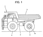
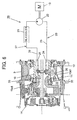
- the dump truck 1 shown in FIG. 1 is used to transport crushed rocks or the like dug in a mine, and is a large one with a payload capacity of more than 100 tons.
- This dump truck 1 has a chassis 2 as a main body, a vessel tiltably mounted on the chassis, and front wheels 4 and rear wheels 5 supporting the chassis 2 such that the chassis 2 can travel.
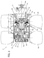
- FIG. 2 designates motors arranged in the respective travel assemblies.
- the motors 8 are inserted and arranged from inboard sides of the respective rear wheels 5 as viewed in a transverse direction of the chassis 2.
- the motors 8 are electric motors, and are rotationally driven with a supply of electric power generated by a diesel engine 19 (shown in FIG. 6 ) mounted on the dump truck 1.
- each rear wheel 5 is comprised of tires 6A, 6B making up double tires and a wheel 9 with these tires 6A,6B mounted thereon.
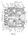
- the travel assembly 7 has the above-described wheel 9, a spindle 10 inserted on a side of an inner periphery of the wheel 9 and non-rotatably fixed on the chassis 2, and two wheel bearings 11, 12 arranged side by side in an axial direction of the spindle 10 between an outer peripheral wall of the spindle 10 and an inner peripheral wall of the wheel 9 to enable rotation of the wheel 9 about the spindle 10.
- the travel assembly 7 also has the above-described motor 8 arranged on a side of an axial end of the spindle 10 and fixedly secured relative to the chassis 2, a shaft 13 non-rotatably connected to an output shaft 8a of the motor 8 via a coupling 40, inserted on a side of an inner periphery of the spindle 10 and extending out from an axial opposite end of the spindle 10, and a reduction gear unit 14 arranged on a side of the opposite end of the spindle 10 and interposed between the shaft 13 and the wheel 9 to transmit power from the shaft 13 to the wheel 9.
- the reduction gear unit 14 has a first planetary gear mechanism 15 and a second planetary gear mechanism 16. These first planetary gear mechanism 15 and second planetary gear mechanism 16 are arranged in an order of the first planetary gear mechanism 15 and second planetary gear mechanism 16 in an axial direction away from the spindle 10.
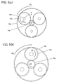
- the first planetary gear mechanism 15 has a first sun gear 15a, three first planetary gears 15b arranged in meshing engagement with the first sun gear 15a (see FIG. 5 (a) ), a first carrier 15c on which three spindles 15c1 (see FIG. 5(a) ) are arranged while rotatably supporting the first planetary gears 15b via two bearings 15c2,15c3, respectively, and a first ring gear 15d arranged in meshing engagement with the three first planetary gears 15b.
- the first carrier 15c is non-rotatably fixed on a hub 17 by plural bolts 17a.
- This hub 17 is fastened together with a second ring gear 16d, which will be described subsequently herein, on the wheel 9 by plural bolts 17b. Therefore, the first carrier 15c is non-rotatably fixed relative to the wheel 9.
- a coupling 18 is fixed by bolts 18a.
- the second planetary gear mechanism 16 has a second sun gear 16a splined to the coupling 18, three second planetary gears 16b (see FIG. 5 (b) ) arranged in meshing engagement with the second sun gear 16a, a second carrier 16c on which three spindles 16c1 (see FIG. 5(b) ) are arranged while rotatably supporting the second planetary gears 16b, respectively, via two bearings 16c2,16c3, and the second ring gear 16d arranged in meshing engagement with the three second planetary gears 16b.
- the second carrier 16c has a cylindrical extension 16c4, which is formed at a radially inner position than the three spindles 16c1 and extends toward the spindle 10.
- This cylindrical extension 16c4 is inserted on the side of the inner periphery of the spindle 10 and is splined to the spindle 10.
- the second ring gear 16d is fastened together with the hub 17 on the wheel 9 by the bolts 17b as mentioned above, and is non-rotatably fixed relative to the wheel 9.
- the first carrier 15c, hub 17 and second ring gear 16d constitute a cover that covers the reduction gear unit 14 on the side of the opposite end of the spindle 10.
- insertion holes 16a1, 16c8 are formed extending in the axial direction, respectively.
- the shaft 13, which extends out on the opposite end of the spindle 10, is non-rotatably connected to the first sun gear 15a in the state that the shaft 13 is inserted and extending through the insertion holes 16a1,16c8.
- the reduction gear unit 14 constructed as described above operates as will be described next.
- the first sun gear 15a rotates together with the shaft 13 in the first planetary gear mechanism 15.
- the rotation of the first sun gear 15a is transmitted to the first planetary gears 15b.
- the three first planetary gears 15b rotate about their own axes, respectively, while revolving around the first sun gear 15a and rotating the wheel, and transmit the rotation of the first sun gear 15a to the first ring gear 15d.
- the first ring gear 15d rotates.
- the second sun gear 16a rotates together with the first ring gear 15d and coupling 18 in the second planetary gear mechanism 16.
- the rotation of the second sun gear 16a is transmitted to the three second planetary gears 16b.
- the second carrier 16c with these second planetary gears 16b supported thereon is connected non-rotatably to the spindle 10
- the second planetary gears 16b rotate about their axes, respectively, without revolving around the second sun gear 16a, and transmit the rotation of the second sun gar 16a to the second ring gear 16d.
- the second ring gear 16d is integrally fixed to the wheel 9 and first carrier 15c, and therefore, rotates together with these wheel 9 and first carrier 15c.
- the second planetary gears 16b may be arranged as many as four.
- the spindle is formed, in its entirety, of a motor accommodating section 10a and a shaft accommodating section 10b.
- the motor accommodating section 10a is of a substantially frusto-conical, hollow form tapered from the chassis 2 toward the reduction gear unit 14 and accommodates the motor 8 inserted from a side of the output shaft 8a thereof.
- the shaft accommodating section 10b is of a substantially cylindrical form extending from an outboard end portion of the motor accommodating section 10a in a direction toward the reduction gear unit 14 and accommodates the shaft 13 inserted and extending therethrough.
- the above-mentioned wheel bearings 11,12 are located on an outer peripheral wall of the shaft accommodating section 10b.
- the motor accommodating section 10a takes up an axial range L1 of the entirety of the spindle 10, while the shaft accommodating section 10b takes up an axial range L2 of the entirety of the spindle 10.
- This spindle 10 is formed of a chassis-side member 10c and a reduction gear unit-side member 10d joined together .
- the chassis-side member 10c takes up an axial range L3 of the entirety of the spindle 10, and is to be fixedly secured on the chassis 2 of the dump truck 1.
- the reduction gear unit-side member 10d is located on a side closer to the reduction gear unit 14 than the chassis-side member 10c, specifically takes up an axial range L4 of the entirety of the spindle 10.
- the joining between the chassis-side member 10c and the reduction gear unit-side member 10d can be achieved by a method such as, for example, welding.
- Designated at numeral 10e in FIG. 3 is a joint between the chassis-side member 10c and the reduction gear unit-side member 10d.
- the chassis-side member 10c is a section of the entirety of the spindle 10, which includes the motor accommodating section 10a.
- the reduction gear unit-side member 10d is a member, which is located on the side of the reduction gear unit relative to a position between the wheel bearings 11,12 and the motor accommodating section 10a in the entirety of the spindle 10. This member is arranged to surround a portion of the shaft 13, at which a distance to a connected part between the output shaft 8a of the motor 8 and the shaft 13, that is, to the coupling 40 and a distance to a connected part between the reduction gear unit 14 and the shaft 13, that is, to the first sun gear 15a become equal to each other.
- a flange 10f for the arrangement of the support bearing 50 has been formed together with the reduction gear unit-side member 10d by casting.
- the support bearing 50 supports the shaft 13 at a portion thereof, which is located between the coupling 40 and the first sun gear 15a.
- the location of the flange 10f is set such that the support bearing 50 can be secured in a neighborhood of a center of a range from the coupling 40 to the first sun gear 15a.
- the support bearing 50 is fitted in a retainer 51 secured on the flange 10f.
- the reduction gear unit 14 is a state immersed in lube oil.
- the spindle 10 is provided with an oil inlet hole 10d1 formed to guide lube oil, which has flowed into the spindle 10, to a space 31 surrounded by the spindle 10, wheel 9 and two bearings 11,12. It is to be noted that in FIG. 4 , sign “L" indicates the level height of the lube oil when the rear wheel 5 is in a stopped state.
- the travel assembly 7 is provided with a cooling circuit 20 for cooling lube oil.
- This cooling circuit 20 has an oil cooler 21, a recovery oil passage 23 for recovering lube oil from the side of the reduction gear unit 14 and guiding it to the oil cooler 21, a re-supply oil passage 27 for guiding lube oil, which has been cooled by the oil cooler 21, to the reduction gear unit 14 from the side of the inner periphery of the spindle 10, and a pump 22 drivable by the diesel engine 19 to produce a flow of lube oil for its circulation through the cooling circuit 20.
- the recovery oil passage 23 has an intra-spindle recovery line 24 inserted on the side of the inner periphery of the spindle 10, an extra-spindle recovery line 25 connecting the intra-spindle recovery line 24 and the oil cooler 21 with each other and provided with the pump 22, and a suction pipe 26 connected to an end portion of the intra-spindle recovery line 24, said end portion being on a side opposite to the oil cooler 21.
- This suction pipe 26 extends through the oil inlet hole 10d1 to a location radially outer than openings of the two bearings 11,12 on the side of the outer periphery of the spindle 10.
- the suction pipe 26 and intra-spindle recovery line 24 are connected to each other via the retainer 51. Through the retainer 51, a line 51a (through hole) is formed to communicate the suction pipe 26 and the intra-spindle recovery line 24 with each other.
- the recovery oil passage 23 also has plural communication holes 30 through which a space 32 on the side of the reduction gear unit 14 and the space 31 between the two bearings 11,12 are communicated to each other. These communication holes 30 are formed through a section of the wheel 9, said section being located on the side of the outer peripheries of the two bearings 11,12.
- the height position of the oil level becomes lower than the height L of the oil level depicted in FIG. 4 because centrifugal force and inertia force act on the lube oil.
- the location of a free end portion of the suction pipe 26, that is, a suction opening 26a is, therefore, set lower than the level height of the lube oil during travel of the dump truck 1.
- the suction pipe 26 is open at a position lower than the height position of the level of the lube oil during travel of the dump truck 1.
- the re-supply oil passage 27 has an intra-spindle re-supply line 28 inserted to the side of the inner periphery of the spindle 10, an extra-spindle re-supply line 29 connecting the intra-spindle re-supply line 28 and the oil cooler 21 with each other, and a discharge pipe 33 connected to an end portion of the intra-spindle re-supply line 28, said end portion being on a side opposite to the side of the oil cooler 21.
- the discharge pipe 33 and the intra-spindle re-supply line 28 are connected to each other via the retainer 51. Through the retainer 51, a line 51b (through hole) is formed to communicate the discharge pipe 33 and the intra-spindle re-supply line 28 with each other.
- the discharge pipe 33 is inserted in the insertion hole 16c8 defined by an inner wall of the cylindrical extension 16c4 of the second carrier 16c.
- the inner wall of the cylindrical extension 16c4 has a first frusto-conical wall portion 16c5 tapered in a direction toward a free end portion of the discharge pipe 33, that is, a discharge opening 33a, a cylindrical wall portion 16c6 extending from the first frusto-conical wall portion 16c5 in a direction toward the second sun gear 16a, and a second frusto-conical wall portion 16c7 flaring from the cylindrical wall portion 16c6 in a direction toward the second planetary gear mechanism 16.
- the discharge opening 33a of the discharge pipe 33 is located facing the cylindrical wall portion 16c6. This construction facilitates the guidance of the lube oil to the reduction gear unit 14 after its delivery from the discharge opening 33a.
- the position of the above-mentioned flange 10f may desirably be set such that the support bearing 50 can be arranged at a center position of a range between the coupling 40 and the first sun gear 15a. In this embodiment, however, the position of the flange 10f is set in the neighborhood of the center position as a matter of convenience for a space in which the suction pipe 26 and discharge pipe 33 are arranged.
- the cooling circuit 20 constructed as described above operates as will be described next.
- the pump 22 is driven by the diesel engine 19 while electric power generated by the diesel engine 19 is supplied to the motor 8.
- the lube oil accumulated within the space 31 between the two bearings 11,12 is drawn up through the suction pipe 26, is guided to the oil cooler 21 through the intra-spindle recovery line 24 and extra-spindle recovery line 25, and is then cooled there.
- the cooled lube oil is delivered from the oil cooler 21 through the extra-spindle re-supply line 29 and intra-spindle re-supply line 28, and is then re-supplied to the reduction gear unit 14 from the cylindrical extension 16c4 formed on the second carrier 16c in the second planetary gear mechanism 16.
- the space 32 on the side of the reduction gear unit 14 is in communication with the space 31 between the two bearings 11,12 through the communication holes 30, a portion of the lube oil supplied to the reduction gear unit 14 is guided to the space 31 and is drawn up again through the suction pipe 26.
- the lube oil in the reduction gear unit 14 is caused to circulate between the reduction gear unit 14 and the oil cooler 21 during operation of the diesel engine 19, that is, during travel of the dump truck 1.
- the spindle 10 is the combination of the chassis-side member 10c and the reduction gear unit-side member 10d joined together, and on the inner peripheral wall of the reduction gear unit-side member 10d as one of these members, the flange 10f for the arrangement of the support bearing 50 is formed together with the reduction gear unit-side member 10d by casting.
- the flange 10f is formed by casting together with the reduction gear unit-side member 10d. It can, therefore, be facilitated to arrange the flange 10f on the inner peripheral wall of the spindle 10 by casing for the arrangement of the support bearing 50.
- the reduction gear unit-side member 10d is a portion of the shaft accommodating section 10b, said portion being located on the side of the reduction gear unit-side member 10d relative to the position between the wheel bearings 11, 12 and the motor accommodating section 10a, specifically the substantially cylindrical portion out of the spindle 10, so that the reduction gear unit-side member 10d can be formed with ease compared with the case in which it is the substantially frusto-conical section.
- the joint 10e between the chassis-side member 10c and the reduction gear unit-side member 10d is located between the wheel bearings 12 and the motor accommodating section 10a, in other words, avoids overlapping the wheel bearings 11,12 in the radial direction of the spindle 10. It is, therefore, possible to control small a stress that occurs at the joint 10e under a load which the spindle 10 receives from the wheel bearings 11,12.
- reaction force F occurs, in the direction opposite to rotation of the first ring gear 15d, on the spindle 15c1 of each first planetary gear 15b in the first planetary gear mechanism 15.
- This reaction force F coincides with the direction in which the wheel 9 is to be rotated.
- the load to be applied to the reduction gear unit can be decreased than the case in which the arrangement of the first planetary gear mechanism 15 and second planetary gear mechanism 16 is opposite to that in the reduction gear unit 14 in the travel assembly 7.
- the lube oil supplied to the wheel bearings 11,12 and reduction gear unit 14 is recovered, cooled and supplied again by the cooling circuit 20.
- the drive assembly 7 can, therefore, contribute to the prevention of malfunction or seizure of the reduction gear unit 14.
- the cooled lube oil is supplied to the reduction gear unit 14. It is, therefore, unnecessary to rely upon the amount of lube oil to compensate for a deterioration in the lubrication performance of the lube oil due to overheating of the lube oil.
- the lube oil can be effectively discharged to the side of the reduction gear unit 14 through the insertion hole 16c8 formed by the cylindrical extension 16c4 owing to the insertion of the discharge pipe 33 in the insertion hole 10b.
- the construction of the cooling circuit 20 in the travel assembly 7 has been realized by the facilitation of insertion of the cylindrical extension 16c4, which is arranged on the second carrier 16c in the second planetary gear mechanism 16, into the spindle 10, because unlike conventional travel assemblies, it has become no longer necessary to arrange a retainer on a reduction gear unit-side end portion of the spindle for the arrangement of the support bearing owing to the arrangement of the support bearing 50 on the flange 10f and the location of the support bearing 50 on the side of the inner periphery of the spindle 10.
- the spindle 10 has been formed by joining the chassis-side member 10c and reduction gear unit-side member 10d together by welding.
- the method of joining the chassis-side member and the reduction gear unit-side member together is not limited to welding.
- the chassis-side member and reduction gear unit-side member may be provided on outer peripheral walls thereof with mutually-facing flanges, and may be bolted together at the positions of the flanges. Further, the chassis-side member and reduction gear unit-side member may also be jointed together by rotary pressure welding.
- the position of the flange 10f is set in the neighborhood of the center position of the space in the above-described embodiment.
- the present invention may be provided with no cooling circuit, and the position of the flange 10f may be set at a position where the support bearing 50 can be arranged at a center position in the range between the coupling 40 and the first sun gear 15a.
- the support bearing 50 is fitted in the retainer 51 secured on the flange 10f, in other words, the support bearing 50 is arranged indirectly on the flange 10f. In the present invention, however, the support bearing may be arranged directly on the flange.
Landscapes
- Engineering & Computer Science (AREA)
- Mechanical Engineering (AREA)
- Chemical & Material Sciences (AREA)
- Combustion & Propulsion (AREA)
- Transportation (AREA)
- Arrangement Or Mounting Of Propulsion Units For Vehicles (AREA)
- Retarders (AREA)
- General Details Of Gearings (AREA)
- Arrangement And Driving Of Transmission Devices (AREA)
Claims (3)
- Ensemble de déplacement (7) pour un camion-benne (1), ledit ensemble de déplacement ayant un roue (9) sur laquelle un pneu (6A ; 6B) doit être monté, une fusée (10) insérée sur un côté d'une périphérie interne de la roue, des paliers de roue (11, 12) agencés entre une paroi périphérique externe de la fusée (10) et une paroi périphérique interne de la roue (9) pour permettre la rotation de la roue autour de la fusée, un moteur (8) agencé sur un côté d'une extrémité de la fusée (10), un arbre d'entraînement (13) raccordé de manière non rotative à un arbre de sortie du moteur (8), inséré sur un côté d'une périphérie interne de la fusée (10) et s'étendant à partir d'une extrémité opposée de la fusée (10), une unité d'engrenage de réduction (14) agencée sur un côté de l'extrémité opposée de la fusée et intercalée entre la roue d'entraînement (13) et la roue (9) pour transmettre la puissance de l'arbre d'entraînement à la roue, dans lequel :la fusée (10) comprend un élément du côté du châssis (10c) destiné à être fixement fixé sur un châssis (2) du camion-benne (1) et un élément du côté de l'unité d'engrenage de réduction (10d) positionné sur un côté plus à proximité de l'unité d'engrenage de réduction (14) que l'élément du côté du châssis (10c), l'élément du côté de l'unité d'engrenage de réduction (10d) est positionné autour d'une partie de l'arbre d'entraînement (13), au niveau de laquelle partie entourée de l'arbre d'entraînement, une distance par rapport à un raccordement entre le moteur (8) et l'arbre d'entraînement et une distance par rapport à un raccordement entre l'unité d'engrenage de réduction (14) et l'arbre d'entraînement deviennent égales par rapport à l'autre, caractérisé en ce que l'ensemble comprend un palier de support (50) agencé sur la fusée (10) et supportant l'arbre d'entraînement (13) sur cette dernière et une bride (10f) sur une paroi périphérie interne de l'élément du côté de l'unité d'engrenage de réduction (10d), pour l'agencement du palier de support (50), a été formée conjointement avec l'élément du côté de l'unité d'engrenage de réduction sous la forme d'un moulage.
- Ensemble de déplacement (7) selon la revendication 1, dans lequel :la fusée (10) est formée, dans son intégralité, avec une section de logement de moteur (10a), qui a une forme sensiblement tronconique, creuse, progressivement rétrécie à partir du châssis (2) vers l'unité d'engrenage de réduction (14) et loge le moteur (8) inséré à partir d'un côté de son arbre de sortie et une section de logement d'arbre d'entraînement (10b) qui a une forme sensiblement cylindrique s'étendant à partir d'une partie d'extrémité externe de la section de logement de moteur (10a) dans une direction allant vers l'unité d'engrenage de réduction (14) et loge l'arbre d'entraînement (13) inséré et s'étendant à travers cette dernière,les paliers de roue (11, 12) sont positionnés sur une paroi périphérique externe de la section de logement d'arbre d'entraînement (10b),l'élément du côté du châssis (10c) est une section de l'intégralité de la fusée (10), ladite section comprenant la section de logement de moteur (10a), etl'élément du côté de l'unité d'engrenage de réduction (10d) est un élément de la section de logement d'arbre d'entraînement (10b), qui est positionné sur un côté de l'unité d'engrenage de réduction (14) par rapport à une position entre les paliers de roue (11, 12) et la section de logement de moteur (10a).
- Ensemble de déplacement (7) selon la revendication 1 ou 2, dans lequel :l'unité d'engrenage de réduction (14) a un premier mécanisme d'engrenage planétaire (15) comprenant un premier planétaire (15a) avec l'arbre d'entraînement (13) raccordé à ce dernier et un second mécanisme d'engrenage planétaire (16) pour transmettre à la roue (9), la puissance transmise par le premier mécanisme d'engrenage planétaire (15), et ces premier et second mécanismes d'engrenage planétaire (15, 16) sont agencés dans un ordre du second mécanisme d'engrenage planétaire (16) et du premier mécanisme d'engrenage planétaire (15) dans une direction axiale à distance de la fusée (10),un second support (16c) dans le second mécanisme d'engrenage planétaire (16) est positionné sur un côté de la fusée (10), des trous d'insertion (16a1, 16c8) sont formés en s'étendant dans la direction axiale à travers le second support (16c) et un second planétaire (16a) dans le second mécanisme d'engrenage planétaire (16), respectivement,l'arbre d'entraînement (13) est raccordé de manière non rotative au premier planétaire (15a) dans le premier mécanisme d'engrenage planétaire (15) dans un état dans lequel l'arbre d'entraînement (13) est inséré, et s'étendant à travers les trous d'insertion (16a1, 16c8),un premier support (15c) dans le premier mécanisme d'engrenage planétaire (15) est fixé de manière non rotative par rapport à la roue (9),une première couronne dentée (15d) dans le premier mécanisme d'engrenage planétaire (15) peut tourner par rapport à la roue (9) et est raccordée de manière non rotative par rapport au second planétaire (16a) dans le second mécanisme d'engrenage planétaire (16), le second support (16c) dans le second mécanisme d'engrenage planétaire (16) est raccordé de manière non rotative à la fusée (10), etune seconde couronne dentée (16d) dans le second mécanisme d'engrenage planétaire (16) est fixée de manière non rotative par rapport à la roue (9).
Applications Claiming Priority (2)
| Application Number | Priority Date | Filing Date | Title |
|---|---|---|---|
| JP2009193307A JP5241652B2 (ja) | 2009-08-24 | 2009-08-24 | ダンプトラックの走行装置 |
| PCT/JP2010/064084 WO2011024723A1 (fr) | 2009-08-24 | 2010-08-20 | Dispositif de roulement pour camion-benne |
Publications (3)
| Publication Number | Publication Date |
|---|---|
| EP2471680A1 EP2471680A1 (fr) | 2012-07-04 |
| EP2471680A4 EP2471680A4 (fr) | 2013-05-29 |
| EP2471680B1 true EP2471680B1 (fr) | 2015-01-28 |
Family
ID=43627829
Family Applications (1)
| Application Number | Title | Priority Date | Filing Date |
|---|---|---|---|
| EP10811773.0A Active EP2471680B1 (fr) | 2009-08-24 | 2010-08-20 | Dispositif de roulement pour camion-benne |
Country Status (5)
| Country | Link |
|---|---|
| US (1) | US8740742B2 (fr) |
| EP (1) | EP2471680B1 (fr) |
| JP (1) | JP5241652B2 (fr) |
| CN (1) | CN102574458B (fr) |
| WO (1) | WO2011024723A1 (fr) |
Families Citing this family (26)
| Publication number | Priority date | Publication date | Assignee | Title |
|---|---|---|---|---|
| CN104470746B (zh) * | 2012-05-10 | 2017-04-19 | 戈尔德霍弗股份公司 | 用于机动车的驱动装置 |
| EP3094871B1 (fr) * | 2014-01-17 | 2020-11-11 | Drillform Technical Services Ltd. | Réducteur intégré de rouleau de pince pour tube de forage |
| CN104960416B (zh) * | 2015-05-25 | 2017-08-11 | 浙江美科斯叉车有限公司 | 一种全方位移动平台动力传输装置 |
| CN105090450B (zh) * | 2015-09-09 | 2017-06-27 | 黄安民 | 轮毂减速器 |
| CN204998341U (zh) * | 2015-10-13 | 2016-01-27 | 徐继钊 | 一种车轮边缘驱动装置 |
| CN105346550B (zh) * | 2015-10-16 | 2018-01-02 | 重庆交通大学 | 带差速器的跨座式单轨车辆双轴动力转向架 |
| CN105835614B (zh) * | 2016-03-25 | 2018-05-08 | 杭州云乐车辆技术有限公司 | 一种应用在汽车上的导轨车轮 |
| DE102017209462A1 (de) * | 2016-08-25 | 2018-03-01 | Zf Friedrichshafen Ag | Radkopf für die angetriebenen Lenkräder von Nutzfahrzeugen |
| JP6695305B2 (ja) * | 2017-06-12 | 2020-05-20 | 日立建機株式会社 | 作業車両の走行装置 |
| NL2019305B1 (en) * | 2017-07-20 | 2019-02-12 | E Traction Europe Bv | Dual tyre rim |
| CN108286589A (zh) * | 2018-03-31 | 2018-07-17 | 重庆市江津区宏盛机械制造有限公司 | 大型重载矿用电动卡车两级减速传动系统 |
| CN108468755A (zh) * | 2018-03-31 | 2018-08-31 | 重庆市江津区宏盛机械制造有限公司 | 大型重载矿用电动卡车二级传动机构 |
| CN108253095A (zh) * | 2018-03-31 | 2018-07-06 | 重庆市江津区宏盛机械制造有限公司 | 大型重载矿用电动卡车减速器总成 |
| CN108662088A (zh) * | 2018-03-31 | 2018-10-16 | 重庆市江津区宏盛机械制造有限公司 | 大型重载矿用电动卡车一级传动机构 |
| JP7111585B2 (ja) | 2018-11-08 | 2022-08-02 | 日立建機株式会社 | ダンプトラック |
| CN109397978A (zh) * | 2018-12-10 | 2019-03-01 | 株洲中车特种装备科技有限公司 | 一种单轨游览列车车轮安装结构 |
| US11498410B2 (en) * | 2019-10-23 | 2022-11-15 | Deere & Company | Powered axle for dual wheel work vehicle |
| CN110877522B (zh) * | 2019-12-02 | 2024-08-23 | 佛山市大耕机械科技有限公司 | 一种前轮驱动装置及三轮扫地车 |
| US11827092B2 (en) | 2020-03-02 | 2023-11-28 | Komatsu America Corp. | Vehicle with front-wheel-assist system |
| JP2024514543A (ja) * | 2021-03-30 | 2024-04-02 | ファン・ローケレン・カンパーニュ,ピーテル・テオドール | 低床バスで使用するための逆ポータルアクスル |
| EP4502427A4 (fr) * | 2022-03-24 | 2026-03-18 | Hitachi Construction Mach Co | Dispositif de déplacement pour véhicule à roues |
| EP4547508A1 (fr) * | 2022-07-01 | 2025-05-07 | Traction Innovation B.V. | Essieu de camion à moteurs électriques à entraînement direct |
| GB2620402B (en) * | 2022-07-05 | 2025-05-28 | Cons Metco Inc | Drive assembly |
| CN115320295B (zh) * | 2022-08-19 | 2024-04-12 | 浙江吉利控股集团有限公司 | 一种汽车及其电驱传动机构 |
| JP7736942B2 (ja) * | 2022-09-29 | 2025-09-09 | 日立建機株式会社 | 作業車両の走行装置 |
| DE102023206072A1 (de) * | 2023-06-28 | 2025-01-02 | Zf Friedrichshafen Ag | Radnabe für eine Nutzfahrzeugantriebsachse |
Citations (1)
| Publication number | Priority date | Publication date | Assignee | Title |
|---|---|---|---|---|
| EP2360047A1 (fr) * | 2010-02-15 | 2011-08-24 | Hitachi Construction Machinery Co., Ltd. | Unité de commande de véhicule pour camion-benne |
Family Cites Families (15)
| Publication number | Priority date | Publication date | Assignee | Title |
|---|---|---|---|---|
| US3770074A (en) * | 1972-04-24 | 1973-11-06 | Gen Motors Corp | Reduction drive for electric axle |
| US4437530A (en) * | 1982-07-16 | 1984-03-20 | Euclid, Inc. | Vehicle axle assembly |
| JPH0626932B2 (ja) * | 1986-03-24 | 1994-04-13 | 三菱重工業株式会社 | エレクトリツクホイ−ルドライブ装置 |
| CA1279582C (fr) | 1986-01-29 | 1991-01-29 | Katsuhiko Iijima | Entrainement electrique de roues |
| JP2571610B2 (ja) * | 1988-08-16 | 1997-01-16 | 本田技研工業株式会社 | アクスルの駆動装置 |
| JP2582415Y2 (ja) * | 1992-02-24 | 1998-10-08 | 株式会社クボタ | 駆動車軸装置 |
| US5382854A (en) * | 1992-07-29 | 1995-01-17 | Kabushikikaisha Equos Research | Electrical motor drive apparatus with planetary gearing |
| WO1994012363A1 (fr) * | 1992-11-24 | 1994-06-09 | Kabushiki Kaisha Komatsu Seisakusho | Systeme de transmission a quatre roues motrices pour gros engin a benne basculante |
| JP3686739B2 (ja) * | 1995-12-27 | 2005-08-24 | ナブテスコ株式会社 | クローラ駆動ユニット |
| US6139464A (en) | 1997-03-08 | 2000-10-31 | Zf Friedrichshafen Ag | Individual wheel drive with a planetary gear |
| WO2003066359A2 (fr) | 2002-02-07 | 2003-08-14 | Euclid-Hitachi Heavy Equipment, Ltd. | Ensemble essieu |
| US7022039B2 (en) | 2003-09-11 | 2006-04-04 | Komatsu America Corp. | Lubrication system for planetary transmission |
| JP4477527B2 (ja) * | 2005-03-22 | 2010-06-09 | 日立建機株式会社 | ダンプトラックの走行駆動装置 |
| JP4699817B2 (ja) * | 2005-06-23 | 2011-06-15 | 日立建機株式会社 | ダンプトラックの走行駆動装置 |
| WO2009016884A1 (fr) * | 2007-07-30 | 2009-02-05 | Hitachi Construction Machinery Co., Ltd. | Moteur d'entraînement de véhicule de chantier |
-
2009
- 2009-08-24 JP JP2009193307A patent/JP5241652B2/ja active Active
-
2010
- 2010-08-20 WO PCT/JP2010/064084 patent/WO2011024723A1/fr not_active Ceased
- 2010-08-20 CN CN201080037720.5A patent/CN102574458B/zh active Active
- 2010-08-20 US US13/389,567 patent/US8740742B2/en active Active
- 2010-08-20 EP EP10811773.0A patent/EP2471680B1/fr active Active
Patent Citations (1)
| Publication number | Priority date | Publication date | Assignee | Title |
|---|---|---|---|---|
| EP2360047A1 (fr) * | 2010-02-15 | 2011-08-24 | Hitachi Construction Machinery Co., Ltd. | Unité de commande de véhicule pour camion-benne |
Also Published As
| Publication number | Publication date |
|---|---|
| US8740742B2 (en) | 2014-06-03 |
| JP5241652B2 (ja) | 2013-07-17 |
| JP2011042322A (ja) | 2011-03-03 |
| US20120142475A1 (en) | 2012-06-07 |
| CN102574458A (zh) | 2012-07-11 |
| CN102574458B (zh) | 2015-03-11 |
| EP2471680A4 (fr) | 2013-05-29 |
| WO2011024723A1 (fr) | 2011-03-03 |
| EP2471680A1 (fr) | 2012-07-04 |
Similar Documents
| Publication | Publication Date | Title |
|---|---|---|
| EP2471680B1 (fr) | Dispositif de roulement pour camion-benne | |
| US8096910B2 (en) | Travel assembly for dump truck | |
| EP3578856B1 (fr) | Véhicule de travail avec un dispositif de déplacement ayant des roues | |
| EP0811521B1 (fr) | Dispositif d'entrainement pour automobiles electriques | |
| EP2568199B1 (fr) | Dispositif de commande de déplacement pour camion-benne | |
| EP2360047B1 (fr) | Unité de commande de véhicule pour camion-benne | |
| US11524574B2 (en) | Axle drive | |
| US8960362B2 (en) | Lubrication arrangement for a drive axle of a haul vehicle | |
| EP2678182B1 (fr) | Cadre de roue, ensemble et procédé | |
| US10677332B2 (en) | Hybrid module including electric motor on front differential | |
| EP2567849A1 (fr) | Dispositif de commande de déplacement pour camion-benne | |
| EP4219981A1 (fr) | Ensemble essieu ayant un module de réduction à engrenages à engrenages multiples | |
| US12292104B2 (en) | Transmission for a vehicle, and drive train having such a transmission | |
| JP4490316B2 (ja) | ダンプトラックの走行駆動装置 | |
| JP7627812B2 (ja) | ホイール式車両の走行装置 | |
| WO2020092518A1 (fr) | Moteur électrique supporté par un lubrifiant doté d'un support de palier | |
| JP4745813B2 (ja) | 遊星歯車減速装置 | |
| JP2006264395A (ja) | ダンプトラックの走行駆動装置 | |
| EP3424764B1 (fr) | Dispositif d'entraînement de moteur-roue | |
| JP2007002919A (ja) | ダンプトラックの走行駆動装置 | |
| JP4477527B2 (ja) | ダンプトラックの走行駆動装置 | |
| JP6691520B2 (ja) | ダンプトラックの走行装置 | |
| US20250237295A1 (en) | Transmission arrangement and drive train with such a transmission arrangement | |
| US20240333112A1 (en) | Arrangement for Grounding a Component | |
| CN119585549A (zh) | 作业车辆的行驶装置 |
Legal Events
| Date | Code | Title | Description |
|---|---|---|---|
| PUAI | Public reference made under article 153(3) epc to a published international application that has entered the european phase |
Free format text: ORIGINAL CODE: 0009012 |
|
| 17P | Request for examination filed |
Effective date: 20120207 |
|
| AK | Designated contracting states |
Kind code of ref document: A1 Designated state(s): AL AT BE BG CH CY CZ DE DK EE ES FI FR GB GR HR HU IE IS IT LI LT LU LV MC MK MT NL NO PL PT RO SE SI SK SM TR |
|
| DAX | Request for extension of the european patent (deleted) | ||
| A4 | Supplementary search report drawn up and despatched |
Effective date: 20130429 |
|
| RIC1 | Information provided on ipc code assigned before grant |
Ipc: F16H 1/32 20060101AFI20130423BHEP Ipc: F16H 57/04 20100101ALI20130423BHEP Ipc: F16C 35/06 20060101ALI20130423BHEP Ipc: B60K 17/04 20060101ALI20130423BHEP Ipc: F16H 57/02 20120101ALI20130423BHEP Ipc: B60K 7/00 20060101ALI20130423BHEP |
|
| 17Q | First examination report despatched |
Effective date: 20140203 |
|
| REG | Reference to a national code |
Ref country code: DE Ref legal event code: R079 Ref document number: 602010022163 Country of ref document: DE Free format text: PREVIOUS MAIN CLASS: B60K0017300000 Ipc: F16H0001460000 |
|
| RIC1 | Information provided on ipc code assigned before grant |
Ipc: F16H 57/02 20120101ALI20140908BHEP Ipc: F16C 35/06 20060101ALI20140908BHEP Ipc: B60B 11/06 20060101ALI20140908BHEP Ipc: F16H 57/04 20100101ALI20140908BHEP Ipc: F16H 1/46 20060101AFI20140908BHEP Ipc: B60K 7/00 20060101ALI20140908BHEP Ipc: B60K 17/04 20060101ALI20140908BHEP Ipc: B60B 35/12 20060101ALI20140908BHEP |
|
| GRAP | Despatch of communication of intention to grant a patent |
Free format text: ORIGINAL CODE: EPIDOSNIGR1 |
|
| INTG | Intention to grant announced |
Effective date: 20141020 |
|
| GRAS | Grant fee paid |
Free format text: ORIGINAL CODE: EPIDOSNIGR3 |
|
| GRAA | (expected) grant |
Free format text: ORIGINAL CODE: 0009210 |
|
| AK | Designated contracting states |
Kind code of ref document: B1 Designated state(s): AL AT BE BG CH CY CZ DE DK EE ES FI FR GB GR HR HU IE IS IT LI LT LU LV MC MK MT NL NO PL PT RO SE SI SK SM TR |
|
| REG | Reference to a national code |
Ref country code: GB Ref legal event code: FG4D |
|
| REG | Reference to a national code |
Ref country code: CH Ref legal event code: EP |
|
| REG | Reference to a national code |
Ref country code: IE Ref legal event code: FG4D |
|
| REG | Reference to a national code |
Ref country code: DE Ref legal event code: R096 Ref document number: 602010022163 Country of ref document: DE Effective date: 20150312 |
|
| REG | Reference to a national code |
Ref country code: AT Ref legal event code: REF Ref document number: 708368 Country of ref document: AT Kind code of ref document: T Effective date: 20150315 |
|
| REG | Reference to a national code |
Ref country code: AT Ref legal event code: MK05 Ref document number: 708368 Country of ref document: AT Kind code of ref document: T Effective date: 20150128 |
|
| REG | Reference to a national code |
Ref country code: NL Ref legal event code: VDEP Effective date: 20150128 |
|
| REG | Reference to a national code |
Ref country code: LT Ref legal event code: MG4D |
|
| PG25 | Lapsed in a contracting state [announced via postgrant information from national office to epo] |
Ref country code: LT Free format text: LAPSE BECAUSE OF FAILURE TO SUBMIT A TRANSLATION OF THE DESCRIPTION OR TO PAY THE FEE WITHIN THE PRESCRIBED TIME-LIMIT Effective date: 20150128 Ref country code: NO Free format text: LAPSE BECAUSE OF FAILURE TO SUBMIT A TRANSLATION OF THE DESCRIPTION OR TO PAY THE FEE WITHIN THE PRESCRIBED TIME-LIMIT Effective date: 20150428 Ref country code: HR Free format text: LAPSE BECAUSE OF FAILURE TO SUBMIT A TRANSLATION OF THE DESCRIPTION OR TO PAY THE FEE WITHIN THE PRESCRIBED TIME-LIMIT Effective date: 20150128 Ref country code: BG Free format text: LAPSE BECAUSE OF FAILURE TO SUBMIT A TRANSLATION OF THE DESCRIPTION OR TO PAY THE FEE WITHIN THE PRESCRIBED TIME-LIMIT Effective date: 20150428 Ref country code: ES Free format text: LAPSE BECAUSE OF FAILURE TO SUBMIT A TRANSLATION OF THE DESCRIPTION OR TO PAY THE FEE WITHIN THE PRESCRIBED TIME-LIMIT Effective date: 20150128 Ref country code: SE Free format text: LAPSE BECAUSE OF FAILURE TO SUBMIT A TRANSLATION OF THE DESCRIPTION OR TO PAY THE FEE WITHIN THE PRESCRIBED TIME-LIMIT Effective date: 20150128 Ref country code: FI Free format text: LAPSE BECAUSE OF FAILURE TO SUBMIT A TRANSLATION OF THE DESCRIPTION OR TO PAY THE FEE WITHIN THE PRESCRIBED TIME-LIMIT Effective date: 20150128 |
|
| PG25 | Lapsed in a contracting state [announced via postgrant information from national office to epo] |
Ref country code: NL Free format text: LAPSE BECAUSE OF FAILURE TO SUBMIT A TRANSLATION OF THE DESCRIPTION OR TO PAY THE FEE WITHIN THE PRESCRIBED TIME-LIMIT Effective date: 20150128 Ref country code: GR Free format text: LAPSE BECAUSE OF FAILURE TO SUBMIT A TRANSLATION OF THE DESCRIPTION OR TO PAY THE FEE WITHIN THE PRESCRIBED TIME-LIMIT Effective date: 20150429 Ref country code: PL Free format text: LAPSE BECAUSE OF FAILURE TO SUBMIT A TRANSLATION OF THE DESCRIPTION OR TO PAY THE FEE WITHIN THE PRESCRIBED TIME-LIMIT Effective date: 20150128 Ref country code: IS Free format text: LAPSE BECAUSE OF FAILURE TO SUBMIT A TRANSLATION OF THE DESCRIPTION OR TO PAY THE FEE WITHIN THE PRESCRIBED TIME-LIMIT Effective date: 20150528 Ref country code: AT Free format text: LAPSE BECAUSE OF FAILURE TO SUBMIT A TRANSLATION OF THE DESCRIPTION OR TO PAY THE FEE WITHIN THE PRESCRIBED TIME-LIMIT Effective date: 20150128 Ref country code: LV Free format text: LAPSE BECAUSE OF FAILURE TO SUBMIT A TRANSLATION OF THE DESCRIPTION OR TO PAY THE FEE WITHIN THE PRESCRIBED TIME-LIMIT Effective date: 20150128 |
|
| REG | Reference to a national code |
Ref country code: DE Ref legal event code: R097 Ref document number: 602010022163 Country of ref document: DE |
|
| PG25 | Lapsed in a contracting state [announced via postgrant information from national office to epo] |
Ref country code: CZ Free format text: LAPSE BECAUSE OF FAILURE TO SUBMIT A TRANSLATION OF THE DESCRIPTION OR TO PAY THE FEE WITHIN THE PRESCRIBED TIME-LIMIT Effective date: 20150128 Ref country code: EE Free format text: LAPSE BECAUSE OF FAILURE TO SUBMIT A TRANSLATION OF THE DESCRIPTION OR TO PAY THE FEE WITHIN THE PRESCRIBED TIME-LIMIT Effective date: 20150128 Ref country code: RO Free format text: LAPSE BECAUSE OF FAILURE TO SUBMIT A TRANSLATION OF THE DESCRIPTION OR TO PAY THE FEE WITHIN THE PRESCRIBED TIME-LIMIT Effective date: 20150128 Ref country code: DK Free format text: LAPSE BECAUSE OF FAILURE TO SUBMIT A TRANSLATION OF THE DESCRIPTION OR TO PAY THE FEE WITHIN THE PRESCRIBED TIME-LIMIT Effective date: 20150128 Ref country code: SK Free format text: LAPSE BECAUSE OF FAILURE TO SUBMIT A TRANSLATION OF THE DESCRIPTION OR TO PAY THE FEE WITHIN THE PRESCRIBED TIME-LIMIT Effective date: 20150128 |
|
| PLBE | No opposition filed within time limit |
Free format text: ORIGINAL CODE: 0009261 |
|
| STAA | Information on the status of an ep patent application or granted ep patent |
Free format text: STATUS: NO OPPOSITION FILED WITHIN TIME LIMIT |
|
| PG25 | Lapsed in a contracting state [announced via postgrant information from national office to epo] |
Ref country code: IT Free format text: LAPSE BECAUSE OF FAILURE TO SUBMIT A TRANSLATION OF THE DESCRIPTION OR TO PAY THE FEE WITHIN THE PRESCRIBED TIME-LIMIT Effective date: 20150128 |
|
| 26N | No opposition filed |
Effective date: 20151029 |
|
| PG25 | Lapsed in a contracting state [announced via postgrant information from national office to epo] |
Ref country code: SI Free format text: LAPSE BECAUSE OF FAILURE TO SUBMIT A TRANSLATION OF THE DESCRIPTION OR TO PAY THE FEE WITHIN THE PRESCRIBED TIME-LIMIT Effective date: 20150128 |
|
| PG25 | Lapsed in a contracting state [announced via postgrant information from national office to epo] |
Ref country code: LU Free format text: LAPSE BECAUSE OF FAILURE TO SUBMIT A TRANSLATION OF THE DESCRIPTION OR TO PAY THE FEE WITHIN THE PRESCRIBED TIME-LIMIT Effective date: 20150820 Ref country code: MC Free format text: LAPSE BECAUSE OF FAILURE TO SUBMIT A TRANSLATION OF THE DESCRIPTION OR TO PAY THE FEE WITHIN THE PRESCRIBED TIME-LIMIT Effective date: 20150128 |
|
| REG | Reference to a national code |
Ref country code: CH Ref legal event code: PL |
|
| GBPC | Gb: european patent ceased through non-payment of renewal fee |
Effective date: 20150820 |
|
| PG25 | Lapsed in a contracting state [announced via postgrant information from national office to epo] |
Ref country code: LI Free format text: LAPSE BECAUSE OF NON-PAYMENT OF DUE FEES Effective date: 20150831 Ref country code: CH Free format text: LAPSE BECAUSE OF NON-PAYMENT OF DUE FEES Effective date: 20150831 |
|
| PG25 | Lapsed in a contracting state [announced via postgrant information from national office to epo] |
Ref country code: BE Free format text: LAPSE BECAUSE OF FAILURE TO SUBMIT A TRANSLATION OF THE DESCRIPTION OR TO PAY THE FEE WITHIN THE PRESCRIBED TIME-LIMIT Effective date: 20150128 |
|
| REG | Reference to a national code |
Ref country code: IE Ref legal event code: MM4A |
|
| REG | Reference to a national code |
Ref country code: FR Ref legal event code: ST Effective date: 20160429 |
|
| PG25 | Lapsed in a contracting state [announced via postgrant information from national office to epo] |
Ref country code: GB Free format text: LAPSE BECAUSE OF NON-PAYMENT OF DUE FEES Effective date: 20150820 Ref country code: IE Free format text: LAPSE BECAUSE OF NON-PAYMENT OF DUE FEES Effective date: 20150820 |
|
| PG25 | Lapsed in a contracting state [announced via postgrant information from national office to epo] |
Ref country code: FR Free format text: LAPSE BECAUSE OF NON-PAYMENT OF DUE FEES Effective date: 20150831 |
|
| PG25 | Lapsed in a contracting state [announced via postgrant information from national office to epo] |
Ref country code: MT Free format text: LAPSE BECAUSE OF FAILURE TO SUBMIT A TRANSLATION OF THE DESCRIPTION OR TO PAY THE FEE WITHIN THE PRESCRIBED TIME-LIMIT Effective date: 20150128 |
|
| PG25 | Lapsed in a contracting state [announced via postgrant information from national office to epo] |
Ref country code: HU Free format text: LAPSE BECAUSE OF FAILURE TO SUBMIT A TRANSLATION OF THE DESCRIPTION OR TO PAY THE FEE WITHIN THE PRESCRIBED TIME-LIMIT; INVALID AB INITIO Effective date: 20100820 Ref country code: SM Free format text: LAPSE BECAUSE OF FAILURE TO SUBMIT A TRANSLATION OF THE DESCRIPTION OR TO PAY THE FEE WITHIN THE PRESCRIBED TIME-LIMIT Effective date: 20150128 |
|
| PG25 | Lapsed in a contracting state [announced via postgrant information from national office to epo] |
Ref country code: CY Free format text: LAPSE BECAUSE OF FAILURE TO SUBMIT A TRANSLATION OF THE DESCRIPTION OR TO PAY THE FEE WITHIN THE PRESCRIBED TIME-LIMIT Effective date: 20150128 |
|
| PG25 | Lapsed in a contracting state [announced via postgrant information from national office to epo] |
Ref country code: TR Free format text: LAPSE BECAUSE OF FAILURE TO SUBMIT A TRANSLATION OF THE DESCRIPTION OR TO PAY THE FEE WITHIN THE PRESCRIBED TIME-LIMIT Effective date: 20150128 |
|
| PG25 | Lapsed in a contracting state [announced via postgrant information from national office to epo] |
Ref country code: PT Free format text: LAPSE BECAUSE OF FAILURE TO SUBMIT A TRANSLATION OF THE DESCRIPTION OR TO PAY THE FEE WITHIN THE PRESCRIBED TIME-LIMIT Effective date: 20150128 Ref country code: MK Free format text: LAPSE BECAUSE OF FAILURE TO SUBMIT A TRANSLATION OF THE DESCRIPTION OR TO PAY THE FEE WITHIN THE PRESCRIBED TIME-LIMIT Effective date: 20150128 |
|
| PG25 | Lapsed in a contracting state [announced via postgrant information from national office to epo] |
Ref country code: AL Free format text: LAPSE BECAUSE OF FAILURE TO SUBMIT A TRANSLATION OF THE DESCRIPTION OR TO PAY THE FEE WITHIN THE PRESCRIBED TIME-LIMIT Effective date: 20150128 |
|
| PGFP | Annual fee paid to national office [announced via postgrant information from national office to epo] |
Ref country code: DE Payment date: 20250702 Year of fee payment: 16 |