EP2472006B1 - Fence able to be made in situ, and method for making it - Google Patents
Fence able to be made in situ, and method for making it Download PDFInfo
- Publication number
- EP2472006B1 EP2472006B1 EP11196125.6A EP11196125A EP2472006B1 EP 2472006 B1 EP2472006 B1 EP 2472006B1 EP 11196125 A EP11196125 A EP 11196125A EP 2472006 B1 EP2472006 B1 EP 2472006B1
- Authority
- EP
- European Patent Office
- Prior art keywords
- containment body
- fence
- containment
- stiffening elements
- situ
- Prior art date
- Legal status (The legal status is an assumption and is not a legal conclusion. Google has not performed a legal analysis and makes no representation as to the accuracy of the status listed.)
- Active
Links
Images

Classifications
-
- E—FIXED CONSTRUCTIONS
- E01—CONSTRUCTION OF ROADS, RAILWAYS, OR BRIDGES
- E01F—ADDITIONAL WORK, SUCH AS EQUIPPING ROADS OR THE CONSTRUCTION OF PLATFORMS, HELICOPTER LANDING STAGES, SIGNS, SNOW FENCES, OR THE LIKE
- E01F13/00—Arrangements for obstructing or restricting traffic, e.g. gates, barricades ; Preventing passage of vehicles of selected category or dimensions
- E01F13/02—Arrangements for obstructing or restricting traffic, e.g. gates, barricades ; Preventing passage of vehicles of selected category or dimensions free-standing; portable, e.g. for guarding open manholes ; Portable signs or signals specially adapted for fitting to portable barriers
-
- E—FIXED CONSTRUCTIONS
- E01—CONSTRUCTION OF ROADS, RAILWAYS, OR BRIDGES
- E01F—ADDITIONAL WORK, SUCH AS EQUIPPING ROADS OR THE CONSTRUCTION OF PLATFORMS, HELICOPTER LANDING STAGES, SIGNS, SNOW FENCES, OR THE LIKE
- E01F15/00—Safety arrangements for slowing, redirecting or stopping errant vehicles, e.g. guard posts or bollards; Arrangements for reducing damage to roadside structures due to vehicular impact
- E01F15/02—Continuous barriers extending along roads or between traffic lanes
- E01F15/08—Continuous barriers extending along roads or between traffic lanes essentially made of walls or wall-like elements ; Cable-linked blocks
- E01F15/081—Continuous barriers extending along roads or between traffic lanes essentially made of walls or wall-like elements ; Cable-linked blocks characterised by the use of a specific material
- E01F15/083—Continuous barriers extending along roads or between traffic lanes essentially made of walls or wall-like elements ; Cable-linked blocks characterised by the use of a specific material using concrete
-
- E—FIXED CONSTRUCTIONS
- E01—CONSTRUCTION OF ROADS, RAILWAYS, OR BRIDGES
- E01F—ADDITIONAL WORK, SUCH AS EQUIPPING ROADS OR THE CONSTRUCTION OF PLATFORMS, HELICOPTER LANDING STAGES, SIGNS, SNOW FENCES, OR THE LIKE
- E01F15/00—Safety arrangements for slowing, redirecting or stopping errant vehicles, e.g. guard posts or bollards; Arrangements for reducing damage to roadside structures due to vehicular impact
- E01F15/02—Continuous barriers extending along roads or between traffic lanes
- E01F15/08—Continuous barriers extending along roads or between traffic lanes essentially made of walls or wall-like elements ; Cable-linked blocks
- E01F15/081—Continuous barriers extending along roads or between traffic lanes essentially made of walls or wall-like elements ; Cable-linked blocks characterised by the use of a specific material
- E01F15/086—Continuous barriers extending along roads or between traffic lanes essentially made of walls or wall-like elements ; Cable-linked blocks characterised by the use of a specific material using plastic, rubber or synthetic materials
-
- E—FIXED CONSTRUCTIONS
- E04—BUILDING
- E04H—BUILDINGS OR LIKE STRUCTURES FOR PARTICULAR PURPOSES; SWIMMING OR SPLASH BATHS OR POOLS; MASTS; FENCING; TENTS OR CANOPIES, IN GENERAL
- E04H17/00—Fencing, e.g. fences, enclosures, corrals
- E04H17/02—Wire fencing, e.g. made of wire mesh
- E04H17/06—Parts for wire fences
- E04H17/063—Fence liners; Vegetation prevention barriers
Definitions
- the present invention concerns a fence able to be made in situ, and a method for making it, according to the preamble of the respective independent claims.
- the fence according to the invention is intended to advantageously be used to fence off areas, in particular with great dimensions, like for example, airports, customs areas, construction sites, forests, roads etc., or else to separate different areas by being placed between them.
- the fence object of the present invention thus fits in the field of road or building constructions, or else in the field of the industry of prefabricated structures.
- the posts are thus filled with cement conglomerates and are then connected to one another with mesh or cables.
- the two shells are obtained from shaped metal sheet that substantially carries out the function of shuttering for making cement posts.
- a further drawback of the aforementioned known type of fence lies in the fact that the posts made from cement do not form a sufficiently resistant barrier and it can consequently be easily violated by breaking or cutting the mesh between two adjacent posts.
- Such barriers are usually obtained with blocks of reinforced concrete that are prefabricated in house and are then transported in situ where they are positioned side by side for making the desired protection fence or barrier.
- the main drawback of this fence lies in the need of transporting very heavy and bulky manufactured products therefore having high transport, and installation costs, in particular for moving the single cement barriers with forklifts.
- the fence therein described comprises a plurality of hollow containment bodies made of an impact-resistant sturdy plastic and each provided with a front wall extending forwardly so that the upper portion thereof overhangs the highway.
- the hollow containment bodies comprise a top wall provided with an elongated longitudinal opening covered by an elongated cover and are aimed to contain ballast of liquid, solid or granular material, which material is susceptible of forcing upwardly the cover and exiting the correspondent hollow bodies upon impact of a vehicle with such bodies.
- Patent US 5,269,623 discloses an inflatable sight barrier for temporarily hiding from view accident scenes.
- the barrier therein described comprises a main base conduit, outwardly projecting leg members and upwardly projecting stanchions supporting a plurality of sight barriers therebetween.
- the main base conduit, the outwardly projecting leg members and the upwardly projecting stanchions are in fluid communication with each other in order to allow the introduction of a pressurized gas to be inflated and expand from a stowed position to an operative position.
- the problem forming the basis of the present invention is to eliminate the aforementioned drawbacks of the prior art, by providing a fence that is able to be made in situ, which has limited bulk.
- Another purpose of the present finding is that of providing a fence that is able to be made in situ, which is easy to transport.
- Another purpose of the present finding is that of providing a fence that can be made in situ, which is cost-effective to make.
- Another purpose of the present finding is that of providing a method for making a fence that is able to be made in situ, which makes it possible to install the fence in a versatile manner on different terrains, be it on flat ground, on steep slopes or on ground with varying slopes.
- Another purpose of the present finding is that of providing a method for making a fence that is able to be made in situ, which is simple and fast to carry out.
- Another purpose of the present finding is that of providing a method for making a fence that is able to be made in situ, which is cost-effective to carry out.
- the fence 1, according to the present invention is intended to advantageously be used to fence off areas, in particular with great dimensions, or rather to be placed between different areas.
- the fence 1 comprises a flexible containment body 2, which extends along a direction of longitudinal extension X, for example for a length of some metres and advantageously comprised in the range of 3 - 5 metres.
- Such a flexible containment body 2 is provided with a base portion 3, which is intended to rest on the ground along the line of the fence be made.
- a plurality of stiffening elements 4 are mechanically associated to the containment body 2 and are advantageously arranged at regular distances with constant pitch along the aforementioned direction of longitudinal extension X and are suitable for supporting the containment body 2 with its base portion 3 resting on the ground.
- the flexible containment body 2 is preferably made from a fabric and in particular from geotextile, suitable for forming a kind of very long sack.
- the geotextile can be obtained with warp and weft filaments of high-density polyethylene, or rather with a high-tenacity polyester or rather again with strips of high tenacity polypropylene.
- the term geotextile however, can also include non-textile material, mechanically needled and thermo-calendered.
- the stiffening elements 4 form the reinforcements that are suitable for mechanically stiffening the flexible containment body 2 so as to allow the latter to contain inside it a mass of cement material withstanding the mechanical stresses and without bulging in an undesired manner, as shall be described in detail in the rest of the description.
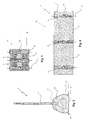
- the stiffening elements 4 are obtained in the form of ribs, preferably made from plastic inserted inside a plurality of peripheral pockets advantageously formed at thickened annular portions of the containment body 2.
- Such pockets are advantageously formed for example through fabric bands or more in general through preferably flexible elements, which are fixed (preferably through seams) on the inner surface of the containment body 2.
- the pockets otherwise can be obtained by sewing folds or overlapping edges of the end portions of separate portions of the containment body 2 while joining them together one after the other.
- the aforementioned ribs 4 extend at least partially transversally with respect to the direction of longitudinal extension X of the containment body 2.
- such ribs 4 extend as a closed loop in planes that are transversal to the direction of longitudinal extension X of the containment body 2 and are shaped to make a communication between adjacent portions 2' of the containment body 2 so as to make it possible to fill the entire containment body with the cement material.
- the stiffening annular element has a T-shaped generatrix section with the leg 4' defining the passage opening 7.
- the containment body 2 can be made as a single body or it can be made in separate portions 2' that are then fixed to one another in succession at the ends through sewing so as to make a single elongated containment body 2.
- the stiffening elements 4 delimit the separate portions 2' of the containment body 2, which define the separate containment chambers, placed in communication with one another from the passage opening 7 formed in the stiffening elements 4.
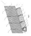
- the containment body 2 thus made is thus deformable between a transportation configuration A, in which it is compacted through folds 6 along its direction of longitudinal extension X, and a configuration of application B, in which it is opened out along the direction of longitudinal extension X with the stiffening elements 4 that support it arranging the base portion 3 resting on the ground.
- the stiffening elements 4 advantageously each project from the pockets with cup-shaped portions 8 facing upwards, which define housing seats 9 for a plurality of support posts 10 of a mesh 11.
- the stiffening elements 4 are in a number that is greater than that of the posts 10 and for this purpose the cup-shaped portions 8 can be closed with lids where there is not the insertion of a post 10. Otherwise, it is possible to foresee stiffening element 4 without cup-shaped portions 8 alternating - with a frequency to be defined as a function of the characteristics of the fence that is desired to be made (height, resistance etc.) - with stiffening elements 4 that are equipped with cup-shaped portions 8 for supporting the posts 10.
- the containment body 2 is moreover advantageously provided with portions projecting outwards 12, preferably in the form of eyelets, formed at the base portion 3, which can undergo mechanical engagement with stakes that are suitable for holding the containment body 2 in the ground in the application position B before filling it with cement material 20.
- the containment body 2 is for this purpose provided with at least one hole 13 for accessing its inner volume intended to convey the cement material 20 to transform the flexible containment body 2 into a rigid body for supporting the mesh 11.
- the flexible containment body 2 is advantageously obtained from a breathable material, indeed like geo-textile previously mentioned, so as to promote the rapid drying of the casting of cement material (preferably concrete obtained with a cement and mixtures of aggregates such as sand and gravel) which has been introduced inside the containment body 2 through the aforementioned hole 13 and that has distributed along the containment body 2 itself thanks to the through openings 7.
- cement material preferably concrete obtained with a cement and mixtures of aggregates such as sand and gravel
- the access hole 13 is for example obtained with a check valve 14 arranged at the bottom of a cup-shaped portion of a stiffening element 4, and preferably at an end portion 2' of the flexible containment body 2.
- the containment body 2 can be filled with cement material 20, for example concrete, from one end thereof.
- cement material 20 for example concrete
- holes 13 can be foreseen at each stiffening element, or else, at further dedicated bushings that are attached to the flexible containment body 2.
- the containment body 2 is made from breathable material, there is no need for a vent hole to be made to allow the air to come out while casting the cement inside the containment body 2 itself.
- a method for making a fence in situ forms the object of the present invention, which in particular can use the fence 1 described above of which, the reference numerals and nomenclature are kept for the sake of simplicity.
- the method initially foresees a step of providing or rather making a sufficient number of flexible containment bodies 2 to fence off the desired area or rather to make the fence 1 of the desired length.
- the flexible containment bodies 2 Once the flexible containment bodies 2 have been loaded in the compact transportation configuration A onto a means of transport (for example a small truck is sufficient), they are then taken near to the area to be fenced off.
- a means of transport for example a small truck is sufficient
- the stiffening elements 4 are advantageously distributed at regular distances along the longitudinal development of the containment body 2.
- Every containment body 2 is arranged in succession until the perimeter of the area to be fenced off is made, or rather, until the division line between two areas to be separated is made.
- the stiffening elements 4 support the containment body 2 arranging the base portion 3 resting on the ground.
- the aforementioned opening out step of the containment bodies 2 on the ground takes place with an accordion-like extension operation.
- each containment body preferably undergoes an attaching step in which it is blocked in position on the ground through stakes, which are engaged with the projecting portions 12 of the containment 2 arranged at the base portion 3.
- a filling step is thus made, in which the inner volume of each containment body 2 receives a flow of cement material from the mouth of a concrete mixer with autoclave, through at least one through hole 13 formed in the containment body 2 itself (and advantageously foreseen at the bottom of a cup-shaped portion 8 of a stiffening element 4).
- the air contained in the inner volume of the containment body 2 is replaced by the cement material 20 and comes out passing through the fabric made from breathable material of the containment body 2.
- the fabric of the containment body allows the water in excess to come out and the cement 20 to dry.
- the present invention it is possible to make a fence in a very short time even on steep uneven ground, since it is possible to easily get there with the flexible containment body in the compact transportation configuration A and then easily open it out, for example along a slope, in the application configuration B.
- the fence object of the present invention as described above advantageously makes it possible to be installed in inaccessible areas without using a crane or similar apparatuses and more in general it can be adapted to be easily installed on surfaces that are in any case irregular.
Landscapes
- Engineering & Computer Science (AREA)
- Architecture (AREA)
- Civil Engineering (AREA)
- Structural Engineering (AREA)
- Devices Affording Protection Of Roads Or Walls For Sound Insulation (AREA)
- Fencing (AREA)
- Refuge Islands, Traffic Blockers, Or Guard Fence (AREA)
Applications Claiming Priority (1)
| Application Number | Priority Date | Filing Date | Title |
|---|---|---|---|
| ITPD2010A000396A IT1404202B1 (it) | 2010-12-30 | 2010-12-30 | Recinzione realizzabile in situ, e metodo per la sua realizzazione |
Publications (3)
| Publication Number | Publication Date |
|---|---|
| EP2472006A2 EP2472006A2 (en) | 2012-07-04 |
| EP2472006A3 EP2472006A3 (en) | 2012-10-03 |
| EP2472006B1 true EP2472006B1 (en) | 2014-06-04 |
Family
ID=43737204
Family Applications (1)
| Application Number | Title | Priority Date | Filing Date |
|---|---|---|---|
| EP11196125.6A Active EP2472006B1 (en) | 2010-12-30 | 2011-12-29 | Fence able to be made in situ, and method for making it |
Country Status (2)
| Country | Link |
|---|---|
| EP (1) | EP2472006B1 (it) |
| IT (1) | IT1404202B1 (it) |
Family Cites Families (7)
| Publication number | Priority date | Publication date | Assignee | Title |
|---|---|---|---|---|
| US3877681A (en) * | 1973-05-29 | 1975-04-15 | Donald F Humphrey | Roadway barrier |
| US4138095A (en) * | 1977-07-27 | 1979-02-06 | Humphrey Donald F | Roadway barrier |
| FR2585047B1 (fr) | 1985-07-22 | 1988-06-17 | Tech Special Securite | Dispositif de securite pour routes, autoroutes et voies urbaines, pour separer deux files de circulation |
| ES2005324A6 (es) | 1987-09-15 | 1989-03-01 | Garcia Ballesteros Angel | Un procedimiento de fabricacion in situ de medianas de seguridad en carreteras. |
| ES2069551T3 (es) | 1988-06-24 | 1995-05-16 | Canon Kk | Composicion de cristal liquido ferroelectrico quiral esmectico y dispositivo de cristal liquido que lo utiliza. |
| US5269623A (en) * | 1992-03-23 | 1993-12-14 | Hanson James L | Rapidly deployable traffic screen |
| DE10311296A1 (de) * | 2002-03-28 | 2003-10-16 | Huesker Synthetic Gmbh | Spülbehälter aus Gewebe |
-
2010
- 2010-12-30 IT ITPD2010A000396A patent/IT1404202B1/it active
-
2011
- 2011-12-29 EP EP11196125.6A patent/EP2472006B1/en active Active
Also Published As
| Publication number | Publication date |
|---|---|
| IT1404202B1 (it) | 2013-11-15 |
| EP2472006A2 (en) | 2012-07-04 |
| ITPD20100396A1 (it) | 2012-07-01 |
| EP2472006A3 (en) | 2012-10-03 |
Similar Documents
| Publication | Publication Date | Title |
|---|---|---|
| US20250084598A1 (en) | Recycled rubber barrier | |
| CA2160063C (en) | Road barrier | |
| US6079904A (en) | Transportable collapsible protective barrier, especially against high water | |
| US6481928B1 (en) | Flexible hydraulic structure and system for replacing a damaged portion thereof | |
| CA2245111C (en) | Improved method and apparatus for constructing hydraulic structures | |
| USRE34691E (en) | Fluid charged roadway barrier | |
| US20160017557A1 (en) | Flood wall protection system | |
| PL201345B1 (pl) | Ściana oporowa, zwłaszcza do ochrony obwałowania i sposób wykonywania ściany oporowej, zwłaszcza do ochrony obwałowania | |
| NL8503003A (nl) | Op een vaste plaats op de grond te plaatsen reservoir en werkwijze voor het vervaardigen daarvan. | |
| CA3131663A1 (en) | Multipurpose stackable self-filling interlocking watertight modular barrier system | |
| US20060099033A1 (en) | Fluid fillable multi-compartment bladder for flow and flood control | |
| EP2812493B1 (de) | Schüttgutbehälter mit verbindungseinrichtung | |
| JP2016532033A (ja) | 洪水防止障壁 | |
| EP1144762B1 (en) | Safety barrier made of steel and/or plastics and earth | |
| PL186997B1 (pl) | Wyrób z materiału oponowego i sposób wytwarzania wyrobu z materiału oponowego oraz zastosowanie wyrobu z materiału oponowego | |
| EP2472006B1 (en) | Fence able to be made in situ, and method for making it | |
| US12320084B2 (en) | Vehicle barrier system and method of construction thereof | |
| WO2013033766A1 (en) | Vehicle separation barrier | |
| ES2236307T3 (es) | Sistema para cubrir un vertedero. | |
| US20240093444A1 (en) | Vehicle barrier system and method of construction thereof | |
| US20080295445A1 (en) | Blast Protection Structures | |
| RU233823U1 (ru) | Устройство для хранения и транспортировки противовесных грузов трубоукладчика | |
| RU233821U1 (ru) | Устройство для хранения и транспортировки противовесных грузов трубоукладчика | |
| RU238403U1 (ru) | Устройство для хранения и транспортировки противовесных грузов трубоукладчика | |
| JP7765049B2 (ja) | 土嚢とその製造方法並びに土嚢構造体とその施工方法 |
Legal Events
| Date | Code | Title | Description |
|---|---|---|---|
| AK | Designated contracting states |
Kind code of ref document: A2 Designated state(s): AL AT BE BG CH CY CZ DE DK EE ES FI FR GB GR HR HU IE IS IT LI LT LU LV MC MK MT NL NO PL PT RO RS SE SI SK SM TR |
|
| AX | Request for extension of the european patent |
Extension state: BA ME |
|
| PUAI | Public reference made under article 153(3) epc to a published international application that has entered the european phase |
Free format text: ORIGINAL CODE: 0009012 |
|
| PUAL | Search report despatched |
Free format text: ORIGINAL CODE: 0009013 |
|
| AK | Designated contracting states |
Kind code of ref document: A3 Designated state(s): AL AT BE BG CH CY CZ DE DK EE ES FI FR GB GR HR HU IE IS IT LI LT LU LV MC MK MT NL NO PL PT RO RS SE SI SK SM TR |
|
| AX | Request for extension of the european patent |
Extension state: BA ME |
|
| RIC1 | Information provided on ipc code assigned before grant |
Ipc: E01F 13/02 20060101AFI20120828BHEP Ipc: E01F 15/08 20060101ALI20120828BHEP Ipc: E04H 12/22 20060101ALI20120828BHEP |
|
| 17P | Request for examination filed |
Effective date: 20130403 |
|
| GRAP | Despatch of communication of intention to grant a patent |
Free format text: ORIGINAL CODE: EPIDOSNIGR1 |
|
| INTG | Intention to grant announced |
Effective date: 20131220 |
|
| GRAS | Grant fee paid |
Free format text: ORIGINAL CODE: EPIDOSNIGR3 |
|
| GRAA | (expected) grant |
Free format text: ORIGINAL CODE: 0009210 |
|
| AK | Designated contracting states |
Kind code of ref document: B1 Designated state(s): AL AT BE BG CH CY CZ DE DK EE ES FI FR GB GR HR HU IE IS IT LI LT LU LV MC MK MT NL NO PL PT RO RS SE SI SK SM TR |
|
| RAP1 | Party data changed (applicant data changed or rights of an application transferred) |
Owner name: INNOVO ENGINEERING AND CONSTRUCTION LIMITED |
|
| REG | Reference to a national code |
Ref country code: GB Ref legal event code: FG4D |
|
| REG | Reference to a national code |
Ref country code: CH Ref legal event code: EP |
|
| REG | Reference to a national code |
Ref country code: AT Ref legal event code: REF Ref document number: 671192 Country of ref document: AT Kind code of ref document: T Effective date: 20140615 |
|
| REG | Reference to a national code |
Ref country code: IE Ref legal event code: FG4D |
|
| REG | Reference to a national code |
Ref country code: DE Ref legal event code: R096 Ref document number: 602011007403 Country of ref document: DE Effective date: 20140717 |
|
| REG | Reference to a national code |
Ref country code: AT Ref legal event code: MK05 Ref document number: 671192 Country of ref document: AT Kind code of ref document: T Effective date: 20140604 |
|
| REG | Reference to a national code |
Ref country code: NL Ref legal event code: VDEP Effective date: 20140604 |
|
| PG25 | Lapsed in a contracting state [announced via postgrant information from national office to epo] |
Ref country code: LT Free format text: LAPSE BECAUSE OF FAILURE TO SUBMIT A TRANSLATION OF THE DESCRIPTION OR TO PAY THE FEE WITHIN THE PRESCRIBED TIME-LIMIT Effective date: 20140604 Ref country code: FI Free format text: LAPSE BECAUSE OF FAILURE TO SUBMIT A TRANSLATION OF THE DESCRIPTION OR TO PAY THE FEE WITHIN THE PRESCRIBED TIME-LIMIT Effective date: 20140604 Ref country code: GR Free format text: LAPSE BECAUSE OF FAILURE TO SUBMIT A TRANSLATION OF THE DESCRIPTION OR TO PAY THE FEE WITHIN THE PRESCRIBED TIME-LIMIT Effective date: 20140905 Ref country code: NO Free format text: LAPSE BECAUSE OF FAILURE TO SUBMIT A TRANSLATION OF THE DESCRIPTION OR TO PAY THE FEE WITHIN THE PRESCRIBED TIME-LIMIT Effective date: 20140904 Ref country code: CY Free format text: LAPSE BECAUSE OF FAILURE TO SUBMIT A TRANSLATION OF THE DESCRIPTION OR TO PAY THE FEE WITHIN THE PRESCRIBED TIME-LIMIT Effective date: 20140604 |
|
| REG | Reference to a national code |
Ref country code: LT Ref legal event code: MG4D |
|
| PG25 | Lapsed in a contracting state [announced via postgrant information from national office to epo] |
Ref country code: SE Free format text: LAPSE BECAUSE OF FAILURE TO SUBMIT A TRANSLATION OF THE DESCRIPTION OR TO PAY THE FEE WITHIN THE PRESCRIBED TIME-LIMIT Effective date: 20140604 Ref country code: RS Free format text: LAPSE BECAUSE OF FAILURE TO SUBMIT A TRANSLATION OF THE DESCRIPTION OR TO PAY THE FEE WITHIN THE PRESCRIBED TIME-LIMIT Effective date: 20140604 Ref country code: LV Free format text: LAPSE BECAUSE OF FAILURE TO SUBMIT A TRANSLATION OF THE DESCRIPTION OR TO PAY THE FEE WITHIN THE PRESCRIBED TIME-LIMIT Effective date: 20140604 Ref country code: AT Free format text: LAPSE BECAUSE OF FAILURE TO SUBMIT A TRANSLATION OF THE DESCRIPTION OR TO PAY THE FEE WITHIN THE PRESCRIBED TIME-LIMIT Effective date: 20140604 Ref country code: HR Free format text: LAPSE BECAUSE OF FAILURE TO SUBMIT A TRANSLATION OF THE DESCRIPTION OR TO PAY THE FEE WITHIN THE PRESCRIBED TIME-LIMIT Effective date: 20140604 |
|
| PG25 | Lapsed in a contracting state [announced via postgrant information from national office to epo] |
Ref country code: SK Free format text: LAPSE BECAUSE OF FAILURE TO SUBMIT A TRANSLATION OF THE DESCRIPTION OR TO PAY THE FEE WITHIN THE PRESCRIBED TIME-LIMIT Effective date: 20140604 Ref country code: RO Free format text: LAPSE BECAUSE OF FAILURE TO SUBMIT A TRANSLATION OF THE DESCRIPTION OR TO PAY THE FEE WITHIN THE PRESCRIBED TIME-LIMIT Effective date: 20140604 Ref country code: ES Free format text: LAPSE BECAUSE OF FAILURE TO SUBMIT A TRANSLATION OF THE DESCRIPTION OR TO PAY THE FEE WITHIN THE PRESCRIBED TIME-LIMIT Effective date: 20140604 Ref country code: CZ Free format text: LAPSE BECAUSE OF FAILURE TO SUBMIT A TRANSLATION OF THE DESCRIPTION OR TO PAY THE FEE WITHIN THE PRESCRIBED TIME-LIMIT Effective date: 20140604 Ref country code: PT Free format text: LAPSE BECAUSE OF FAILURE TO SUBMIT A TRANSLATION OF THE DESCRIPTION OR TO PAY THE FEE WITHIN THE PRESCRIBED TIME-LIMIT Effective date: 20141006 Ref country code: EE Free format text: LAPSE BECAUSE OF FAILURE TO SUBMIT A TRANSLATION OF THE DESCRIPTION OR TO PAY THE FEE WITHIN THE PRESCRIBED TIME-LIMIT Effective date: 20140604 |
|
| PG25 | Lapsed in a contracting state [announced via postgrant information from national office to epo] |
Ref country code: PL Free format text: LAPSE BECAUSE OF FAILURE TO SUBMIT A TRANSLATION OF THE DESCRIPTION OR TO PAY THE FEE WITHIN THE PRESCRIBED TIME-LIMIT Effective date: 20140604 Ref country code: IS Free format text: LAPSE BECAUSE OF FAILURE TO SUBMIT A TRANSLATION OF THE DESCRIPTION OR TO PAY THE FEE WITHIN THE PRESCRIBED TIME-LIMIT Effective date: 20141004 Ref country code: NL Free format text: LAPSE BECAUSE OF FAILURE TO SUBMIT A TRANSLATION OF THE DESCRIPTION OR TO PAY THE FEE WITHIN THE PRESCRIBED TIME-LIMIT Effective date: 20140604 |
|
| REG | Reference to a national code |
Ref country code: DE Ref legal event code: R097 Ref document number: 602011007403 Country of ref document: DE |
|
| PLBE | No opposition filed within time limit |
Free format text: ORIGINAL CODE: 0009261 |
|
| STAA | Information on the status of an ep patent application or granted ep patent |
Free format text: STATUS: NO OPPOSITION FILED WITHIN TIME LIMIT |
|
| PG25 | Lapsed in a contracting state [announced via postgrant information from national office to epo] |
Ref country code: DK Free format text: LAPSE BECAUSE OF FAILURE TO SUBMIT A TRANSLATION OF THE DESCRIPTION OR TO PAY THE FEE WITHIN THE PRESCRIBED TIME-LIMIT Effective date: 20140604 |
|
| 26N | No opposition filed |
Effective date: 20150305 |
|
| REG | Reference to a national code |
Ref country code: DE Ref legal event code: R097 Ref document number: 602011007403 Country of ref document: DE Effective date: 20150305 |
|
| PG25 | Lapsed in a contracting state [announced via postgrant information from national office to epo] |
Ref country code: BE Free format text: LAPSE BECAUSE OF FAILURE TO SUBMIT A TRANSLATION OF THE DESCRIPTION OR TO PAY THE FEE WITHIN THE PRESCRIBED TIME-LIMIT Effective date: 20140604 |
|
| PG25 | Lapsed in a contracting state [announced via postgrant information from national office to epo] |
Ref country code: LU Free format text: LAPSE BECAUSE OF FAILURE TO SUBMIT A TRANSLATION OF THE DESCRIPTION OR TO PAY THE FEE WITHIN THE PRESCRIBED TIME-LIMIT Effective date: 20141229 Ref country code: SI Free format text: LAPSE BECAUSE OF FAILURE TO SUBMIT A TRANSLATION OF THE DESCRIPTION OR TO PAY THE FEE WITHIN THE PRESCRIBED TIME-LIMIT Effective date: 20140604 |
|
| REG | Reference to a national code |
Ref country code: CH Ref legal event code: PL |
|
| REG | Reference to a national code |
Ref country code: IE Ref legal event code: MM4A |
|
| PG25 | Lapsed in a contracting state [announced via postgrant information from national office to epo] |
Ref country code: IE Free format text: LAPSE BECAUSE OF NON-PAYMENT OF DUE FEES Effective date: 20141229 Ref country code: LI Free format text: LAPSE BECAUSE OF NON-PAYMENT OF DUE FEES Effective date: 20141231 Ref country code: CH Free format text: LAPSE BECAUSE OF NON-PAYMENT OF DUE FEES Effective date: 20141231 |
|
| REG | Reference to a national code |
Ref country code: FR Ref legal event code: PLFP Year of fee payment: 5 |
|
| PG25 | Lapsed in a contracting state [announced via postgrant information from national office to epo] |
Ref country code: SM Free format text: LAPSE BECAUSE OF FAILURE TO SUBMIT A TRANSLATION OF THE DESCRIPTION OR TO PAY THE FEE WITHIN THE PRESCRIBED TIME-LIMIT Effective date: 20140604 |
|
| PG25 | Lapsed in a contracting state [announced via postgrant information from national office to epo] |
Ref country code: MC Free format text: LAPSE BECAUSE OF FAILURE TO SUBMIT A TRANSLATION OF THE DESCRIPTION OR TO PAY THE FEE WITHIN THE PRESCRIBED TIME-LIMIT Effective date: 20140604 |
|
| PG25 | Lapsed in a contracting state [announced via postgrant information from national office to epo] |
Ref country code: BG Free format text: LAPSE BECAUSE OF FAILURE TO SUBMIT A TRANSLATION OF THE DESCRIPTION OR TO PAY THE FEE WITHIN THE PRESCRIBED TIME-LIMIT Effective date: 20140604 |
|
| PG25 | Lapsed in a contracting state [announced via postgrant information from national office to epo] |
Ref country code: TR Free format text: LAPSE BECAUSE OF FAILURE TO SUBMIT A TRANSLATION OF THE DESCRIPTION OR TO PAY THE FEE WITHIN THE PRESCRIBED TIME-LIMIT Effective date: 20140604 Ref country code: HU Free format text: LAPSE BECAUSE OF FAILURE TO SUBMIT A TRANSLATION OF THE DESCRIPTION OR TO PAY THE FEE WITHIN THE PRESCRIBED TIME-LIMIT; INVALID AB INITIO Effective date: 20111229 Ref country code: MT Free format text: LAPSE BECAUSE OF FAILURE TO SUBMIT A TRANSLATION OF THE DESCRIPTION OR TO PAY THE FEE WITHIN THE PRESCRIBED TIME-LIMIT Effective date: 20140604 |
|
| REG | Reference to a national code |
Ref country code: FR Ref legal event code: PLFP Year of fee payment: 6 |
|
| REG | Reference to a national code |
Ref country code: FR Ref legal event code: PLFP Year of fee payment: 7 |
|
| PG25 | Lapsed in a contracting state [announced via postgrant information from national office to epo] |
Ref country code: MK Free format text: LAPSE BECAUSE OF FAILURE TO SUBMIT A TRANSLATION OF THE DESCRIPTION OR TO PAY THE FEE WITHIN THE PRESCRIBED TIME-LIMIT Effective date: 20140604 |
|
| REG | Reference to a national code |
Ref country code: FR Ref legal event code: RM Effective date: 20180622 |
|
| PG25 | Lapsed in a contracting state [announced via postgrant information from national office to epo] |
Ref country code: AL Free format text: LAPSE BECAUSE OF FAILURE TO SUBMIT A TRANSLATION OF THE DESCRIPTION OR TO PAY THE FEE WITHIN THE PRESCRIBED TIME-LIMIT Effective date: 20140604 |
|
| P01 | Opt-out of the competence of the unified patent court (upc) registered |
Effective date: 20230307 |
|
| PGFP | Annual fee paid to national office [announced via postgrant information from national office to epo] |
Ref country code: GB Payment date: 20251219 Year of fee payment: 15 |
|
| PGFP | Annual fee paid to national office [announced via postgrant information from national office to epo] |
Ref country code: IT Payment date: 20251218 Year of fee payment: 15 |
|
| PGFP | Annual fee paid to national office [announced via postgrant information from national office to epo] |
Ref country code: FR Payment date: 20251222 Year of fee payment: 15 |
|
| PGFP | Annual fee paid to national office [announced via postgrant information from national office to epo] |
Ref country code: DE Payment date: 20251230 Year of fee payment: 15 |