EP2472023B1 - Abdeckungsvorrichtung, die variable Verdunkelungsmittel umfasst, und Schutzraum mit einer solchen Abdeckung - Google Patents
Abdeckungsvorrichtung, die variable Verdunkelungsmittel umfasst, und Schutzraum mit einer solchen Abdeckung Download PDFInfo
- Publication number
- EP2472023B1 EP2472023B1 EP11306800.1A EP11306800A EP2472023B1 EP 2472023 B1 EP2472023 B1 EP 2472023B1 EP 11306800 A EP11306800 A EP 11306800A EP 2472023 B1 EP2472023 B1 EP 2472023B1
- Authority
- EP
- European Patent Office
- Prior art keywords
- covering device
- blades
- shelter
- blade
- longitudinal side
- Prior art date
- Legal status (The legal status is an assumption and is not a legal conclusion. Google has not performed a legal analysis and makes no representation as to the accuracy of the status listed.)
- Not-in-force
Links
- 239000002023 wood Substances 0.000 claims description 5
- 230000007935 neutral effect Effects 0.000 claims description 4
- 239000007787 solid Substances 0.000 claims description 3
- 230000000284 resting effect Effects 0.000 claims description 2
- 238000005192 partition Methods 0.000 claims 2
- 230000004308 accommodation Effects 0.000 claims 1
- 230000001419 dependent effect Effects 0.000 claims 1
- 238000004519 manufacturing process Methods 0.000 description 2
- 239000007769 metal material Substances 0.000 description 2
- 229920003023 plastic Polymers 0.000 description 2
- 238000004026 adhesive bonding Methods 0.000 description 1
- 238000010276 construction Methods 0.000 description 1
- 230000000694 effects Effects 0.000 description 1
- 239000011521 glass Substances 0.000 description 1
- 238000003780 insertion Methods 0.000 description 1
- 230000037431 insertion Effects 0.000 description 1
- 239000000463 material Substances 0.000 description 1
- 238000012986 modification Methods 0.000 description 1
- 230000004048 modification Effects 0.000 description 1
- 239000004417 polycarbonate Substances 0.000 description 1
- 229920000515 polycarbonate Polymers 0.000 description 1
- 238000007789 sealing Methods 0.000 description 1
- 238000006467 substitution reaction Methods 0.000 description 1
Images




Classifications
-
- E—FIXED CONSTRUCTIONS
- E04—BUILDING
- E04D—ROOF COVERINGS; SKY-LIGHTS; GUTTERS; ROOF-WORKING TOOLS
- E04D3/00—Roof covering by making use of flat or curved slabs or stiff sheets
- E04D3/02—Roof covering by making use of flat or curved slabs or stiff sheets of plane slabs, slates, or sheets, or in which the cross-section is unimportant
- E04D3/06—Roof covering by making use of flat or curved slabs or stiff sheets of plane slabs, slates, or sheets, or in which the cross-section is unimportant of glass or other translucent material; Fixing means therefor
-
- E—FIXED CONSTRUCTIONS
- E04—BUILDING
- E04B—GENERAL BUILDING CONSTRUCTIONS; WALLS, e.g. PARTITIONS; ROOFS; FLOORS; CEILINGS; INSULATION OR OTHER PROTECTION OF BUILDINGS
- E04B7/00—Roofs; Roof construction with regard to insulation
- E04B7/16—Roof structures with movable roof parts
- E04B7/166—Roof structures with movable roof parts characterised by a translation movement of the movable roof part, with or without additional movements
-
- E—FIXED CONSTRUCTIONS
- E04—BUILDING
- E04F—FINISHING WORK ON BUILDINGS, e.g. STAIRS, FLOORS
- E04F10/00—Sunshades, e.g. Florentine blinds or jalousies; Outside screens; Awnings or baldachins
- E04F10/08—Sunshades, e.g. Florentine blinds or jalousies; Outside screens; Awnings or baldachins of a plurality of similar rigid parts, e.g. slabs, lamellae
- E04F10/10—Sunshades, e.g. Florentine blinds or jalousies; Outside screens; Awnings or baldachins of a plurality of similar rigid parts, e.g. slabs, lamellae collapsible or extensible; metallic Florentine blinds; awnings with movable parts such as louvres
-
- E—FIXED CONSTRUCTIONS
- E04—BUILDING
- E04H—BUILDINGS OR LIKE STRUCTURES FOR PARTICULAR PURPOSES; SWIMMING OR SPLASH BATHS OR POOLS; MASTS; FENCING; TENTS OR CANOPIES, IN GENERAL
- E04H1/00—Buildings or groups of buildings for dwelling or office purposes; General layout, e.g. modular co-ordination or staggered storeys
- E04H1/12—Small buildings or other erections for limited occupation, erected in the open air or arranged in buildings, e.g. kiosks, waiting shelters for bus stops or for filling stations, roofs for railway platforms, watchmen's huts or dressing cubicles
- E04H1/1205—Small buildings erected in the open air
Definitions
- the present invention relates to the field of equipment and annexes of buildings, in particular the field of coverage and protection of adjoining or separate areas of a dwelling, such as terraces, verandas, winter gardens, gardens, arbours or similar temporary or permanent shelters, in particular those having a roof at least partially in the form of a canopy.
- the invention relates more particularly to a cover device incorporating adjustable means of occultation, and a shelter provided with such a device.
- cover constructions of the aforementioned type are already known, particularly in relation to laterally open shelters (eg covered terraces, arbours) or closed (eg winter gardens, verandas, greenhouses).
- Such covers must generally meet the following two types of user wishes: weather protection and the possibility of adjusting natural lighting.
- the solutions proposed to date therefore consist of a sealed and substantially transparent cover associated or incorporating variable occlusion means, mounted on the outer or inner side relative to the cover.
- a possible solution according to the preamble of claim 1 is for example illustrated by the document FR 2,355,445 .
- the transparent cover plates When this structure has significant overhangs, to have large open openings and allow a significant light passage (wish sufficient natural lighting even in low light outside), the transparent cover plates must present a constitution rigid enough to be self-supporting with a limited spire. In the case of glass plates or transparent plastics, this implies a large thickness, resulting in a significant weight and a high cost.
- the present invention is intended in particular to overcome the aforementioned drawbacks, while at the same time best meeting the wishes set out and possibly allowing the use of non-metallic materials, in particular for the support structure.
- the subject of the present invention is a covering device provided with adjustable means of occultation, essentially comprising a frame or support frame, possibly with a modular structure, comprising in particular at least two support rails between which, or between each pair of which a plurality of pivotable blades are mounted around axes perpendicular to said longitudinal members, the latter supporting together, at least in two, at least one watertight cover plate allowing solar light to at least partially pass, covering device characterized in that the or each cover plate rests on the adjustable blades in the various possible pivoting positions of the latter.
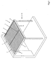
- This device essentially comprises a frame or support frame 3, possibly with a modular structure, comprising in particular at least two support rails 4 between which, or between each pair of which are mounted a plurality of blades 2 pivotally pivotable about perpendicular X axes said longitudinal members 4, the latter supporting together, at least two, at least one waterproof cover plate 5 allowing at least partially pass sunlight.
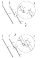
- the or each cover plate 5 rests on the steerable blades 2 (forming the adjustable occulting means) in the different possible pivoting positions of the latter.
- the orientable blades 2 forming variable occlusion means are used as multiple supports and distributed to support the cover plate 5.
- the occultation blades 2 are protected from the weather by said plate 5, which is preferably mounted with a slight clearance or forms an at least slightly deformable panel, in order to allow to absorb the constructive tolerances related to said blades 2 and to their assembly.
- the contact between the blades 2 and the plate 5 must be at least partially slippery and non-aggressive, so as not to damage said plate 5 and not to require too much force during the operation of the blades 2.
- the cover device 1 has a lightened structure, allowing the implementation of non-metallic materials for the realization of the frame 3 and / or for its support or attachment.
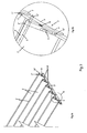
- each orientable blade 2 is in contact with the cover plate 5 by one of its longitudinal edges 2 ', preferably by a substantially linear contact zone, and the edges 2' of the blades in contact with the or a plate of cover 5 have a rounded configuration, the pivot axes X passing through the centers of arcs corresponding to the periphery of the cross sections of said longitudinal edges 2 'rounded.
- each plate 2 is advantageously secured, at each of its two ends 2 "opposite, to one of the longitudinal members 4 of the support frame 3 by a hinge 6 to pivoting, being substantially kept freely suspended at the two opposite ends 2 "of said blade 2.
- said blades 2 are advantageously connected, at least kinematically, to each other by at least one means 7 common control or drive kinematically connected to an operating member and / or actuator 8 (button or operating handle, electric motor, ...) for example by means of a linkage or a cable 8 ').
- the blades 2 are movable in rotation about their pivot axis X, in both directions or directions relative to their substantially vertical neutral position (substantially vertical blades - representation in solid lines of the Figure 5C ) on an angular range extending substantially up to 90 ° on each side of the vertical neutral position (limited by the abutment of the strip 7).
- each profiled orientable blade 2 is equipped, at at least one of its ends 2", with an interconnection piece 9, simultaneously providing its pivotable mounting on one of the two longitudinal members 4 support of said blade 2 and its attachment to a common control or drive means 7, for example in the form of a strip or bar linkage, a second interconnection piece, optionally identical to the aforementioned interconnection piece 9, ensuring pivotal mounting on the other of the two longitudinal members 4 support ( figures 7 and 8 ).
- each interconnection piece 9 has a body 9 'substantially in the form of a plate, intended to be attached to the end edge 10 concerned of the blade 2 corresponding, with arrangement, between them, a passage 11 for the common drive means 7, the fastening of this part 9 with said blade 2 being formed by a locked interlocking, for example an interlocking via minus a lug or finger 12, 12 'and a locking by at least one screw 13.
- each interconnection piece 9 has a wafer-shaped body 9 'provided, on the one hand, with a first face, with at least two lugs or fingers 12, 12' for interlocking in adapted spaced housings 10 ', formed in the face of the end edge 10 of the corresponding blade 2 and, on the other hand, on the opposite face, of a finger or lug 12' for making a connection articulated pivotally 6 with the amount 4 concerned, said body 9 'being further provided with at least one orifice 12' '' through, for the passage of a screw 13 for example.
- the hollow body 9 ' may, for example, also have a hollow structure to cap the corresponding end edge of the blade 2 concerned, the interlocking assembly being locked by screwing or gluing.
- the X axes of the various pivoting links 6 of the successive blades 2 are preferably spaced apart by a distance substantially corresponding to the length of the blades 2.
- the common drive or control means 7 has an elongated and modular constitution, for example in the form of segments 7 'assembled end-to-end by snap-fit engagement with resilient interlocking, and includes locals 7''. hanging with the interconnection pieces 9, regularly spaced along said means 7, for example for attachment at pins or fingers 12 'for securing said parts 9 with the blades 2.
- one of the ends of the segments 7 ' may be equipped with a male assembly member 17, preferably with an elastically deformable constitution, and the other end of the segments 7' may be equipped with a housing 17 ', forming a female receiving site and adapted to receive, with elastic locking, the male assembly member 17, thus allowing the realization of a means 7 of adaptable length, by simple snap.
- the orientable profiled blades 2, as well as possibly the support frame are made in wood, preferably in solid wood.
- blades 2 of solid wood is facilitated in particular by the provision of interconnection pieces 9 forming a mounting and assembly interface for these blades 2.
- the or each sealing cover plate 5 is mounted between two longitudinal members 4 by engagement of two opposite lateral edges 5 'in grooves 4' of said longitudinal members 4, the mounting of the or each plate 5 in the grooves 4 'being blocked by a screw or a similar stop and said plate 5 possibly resting on at least one intermediate spar 4.
- a removable front cross member 14 with decorative and / or structural functions, can be provided between the ends of the rails 4 having the grooves 4 '(the insertion side of the plate 5).
- This crosspiece 14 may in particular serve as a band and hide a gutter (not shown) secured to a cross member 14 'extending under the front edge of the plate 5 in the mounted state
- the covering device 1 can advantageously be constituted by at least two modules 1 ', arranged side by side, each comprising at least two parallel longitudinal members 4 between which are mounted a plurality of blades 2 and a substantially transparent cover plate 5, these modules 1 'consisting of preassembled units and secured together to form the cover device 1 or forming the fragmentary parts constituting a cover device 1 in one piece, especially with a frame or support frame 3 in one piece.
- the present invention also relates to a shelter 15, in particular a terrace shelter adjoining a main building or autonomous shelter, particularly of the arbor type or the like, essentially comprising a roof and a support structure.
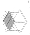
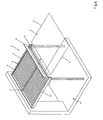
- This shelter 15 is characterized in that the roof, or at least part of the roof, is constituted by a covering device 1 as described above (see Figures 1 to 3 ).
- the figure 3 at least one of the side faces of the shelter 15 may be at least partially closed by a wall 16 adapted to let at least partially the light.
- the at least one of the side walls 16 has a constitution similar to that of the covering device 1 forming the roof or at least part of the roof.
Landscapes
- Engineering & Computer Science (AREA)
- Architecture (AREA)
- Civil Engineering (AREA)
- Structural Engineering (AREA)
- Physics & Mathematics (AREA)
- Electromagnetism (AREA)
- Blinds (AREA)
- Specific Sealing Or Ventilating Devices For Doors And Windows (AREA)
- Fencing (AREA)
Claims (14)
- Abdeckungsvorrichtung (1), die mit einstellbaren Verdunkelungsmitteln versehen ist, umfassend ein Gestell oder einen Stützrahmen (3), eventuell mit modularer Struktur, umfassend insbesondere mindestens zwei Längsträger (4) als Stütze, zwischen denen oder zwischen jedem Paar von denen, eine Vielzahl von Lamellen (2) montiert ist, die durch Schwenken um Achsen senkrecht auf die Längsträger ausrichtbar sind, wobei diese letztgenannten gemeinsam, zumindest paarweise, mindestens eine dichte Abdeckungsplatte (5) tragen, die zumindest teilweise das Sonnenlicht durchlässt,
dadurch gekennzeichnet, dass die oder jede Abdeckungsplatte (5) auf den ausrichtbaren Lamellen (2) in den verschiedenen möglichen Schwenkpositionen dieser letztgenannten aufliegt. - Abdeckungsvorrichtung nach Anspruch 1, dadurch gekennzeichnet, dass jede ausrichtbare Lamelle (2) mit der Abdeckungsplatte (5) mit einem ihrer Längsränder (2'), vorzugsweise mit einer im Wesentlichen geraden Kontaktzone, in Kontakt ist, und dass die Ränder (2') der Lamellen, die mit der oder einer Abdeckungsplatte (5) in Kontakt sind, eine abgerundete Ausführung aufweisen, wobei die Schwenkachsen (X) durch die Mitten der Kreisbögen entsprechend den Umfängen der Querschnitte der abgerundeten Längsränder (2') verlaufen.
- Abdeckungsvorrichtung nach einem der Ansprüche 1 und 2, dadurch gekennzeichnet, dass jede Lamelle im Bereich jedes ihrer beiden gegenüberliegenden Enden (2'') mit einem der Längsträger (4) des Stützrahmens (3) durch ein Schwenkgelenk (6) verbunden ist, wobei sie im Wesentlichen im Bereich der beiden gegenüberliegenden Enden (2'') der Lamelle (2) frei hängend gehalten wird, und dass die Lamellen (2) zumindest kinematisch miteinander durch mindestens ein gemeinsames Steuer- oder Antriebsmittel (7) verbunden sind, das kinematisch mit einem Betätigungs- und/oder Antriebselement (8) verbunden ist.
- Abdeckungsvorrichtung nach einem der Ansprüche 1 bis 3, dadurch gekennzeichnet, dass jede profilierte ausrichtbare Lamelle (2) an mindestens einem ihrer Enden (2'') mit einem Verbindungsteil (9) ausgestattet ist, das gleichzeitig ihre schwenkbare Montage auf einem der beiden Längsträger (4) zur Abstützung der Lamelle (2) und ihre Befestigung an einem gemeinsamen Steuer- oder Antriebsmittel (7), beispielsweise in Form einer Leiste oder einer Stange eines Gestänges, gewährleistet, wobei ein zweites Verbindungsteil, das eventuell mit dem vorgenannten Verbindungsteil (9) identisch ist, die schwenkbare Montage auf dem anderen der beiden Längsträger (4) zur Abstützung.
- Abdeckungsvorrichtung nach Anspruch 4, dadurch gekennzeichnet, dass jedes Verbindungsteil (9) einen Körper (9') im Wesentlichen in Form einer Platte aufweist, der dazu bestimmt ist, auf den betreffenden Endrand (10) der entsprechenden Lamelle (2) aufgesetzt zu werden, wobei zwischen ihnen ein Durchgang (11) für das gemeinsame Antriebsmittel (7) vorgesehen ist, wobei die Verbindung dieses Teils (9) mit der Lamelle (2) durch ein verriegeltes Einfügen erfolgt, beispielsweise ein Einfügen mit Hilfe mindestens eines Hakens oder Fingers (12, 12') und eine Verriegelung mit Hilfe mindestens einer Schraube (13).
- Abdeckungsvorrichtung nach Anspruch 5, dadurch gekennzeichnet, dass jedes Verbindungsteil (9) einen Körper (9') in Plattenform aufweist, der einerseits auf einer ersten Seite mit mindestens zwei Haken oder Fingern (12, 12') für ein Einfügen in angepasste beabstandete Lagerungen (10'), die in der Seite des Endrandes (10) der entsprechenden Lamelle (2) vorgesehen sind, und andererseits auf der gegenüberliegenden Seite mit einem Finger oder Haken (12') für die Herstellung einer gelenkigen Schwenkverbindung (6) mit dem betreffenden Ständer (4) versehen ist, wobei der Körper (9') ferner mit mindestens einer durchgehenden Öffnung (12''') beispielsweise für den Durchgang einer Schraube (13) versehen ist.
- Abdeckungsvorrichtung nach einem der Ansprüche 4 bis 6, dadurch gekennzeichnet, dass das gemeinsame Antriebs- oder Steuermittel (7) eine längliche und modulare Ausführung, beispielsweise in Form von Segmenten (7'), die Stoß an Stoß durch Formentsprechung mit elastischem Einrasten verbunden sind, aufweist, und dass sie Bereiche (7'') zur Befestigung an den Verbindungsteilen (9), die regelmäßig entlang des Mittels (7) beabstandet sind, umfasst, beispielsweise für eine Befestigung im Bereich von Haken oder Fingern (12') zur Verbindung der Teile (9) mit den Lamellen (2).
- Abdeckungsvorrichtung nach einem der Ansprüche 1 bis 7, dadurch gekennzeichnet, dass die ausrichtbaren profilierten Lamellen (2) sowie eventuell der Stützrahmen aus Holz, vorzugsweise aus massivem Holz, hergestellt sind.
- Abdeckungsvorrichtung nach Anspruch 2 oder einem der Ansprüche 3 bis 8, sofern er mit dem Anspruch 2 verbunden ist, dadurch gekennzeichnet, dass die Lamellen (2) in Drehung um ihre Schwenkachse (X) in Bezug zu einer im Wesentlichen vertikalen neutralen Stellung in einem Winkelbereich beweglich sind, wobei sie sich praktisch bis zu 90° auf jeder Seite der neutralen Stellung erstrecken.
- Abdeckungsvorrichtung nach einem der Ansprüche 1 bis 9, dadurch gekennzeichnet, dass die oder jede dichte Abdeckungsplatte (5) zwischen zwei Längsträgern (4) durch Eingreifen von zwei gegenüberliegenden Seitenrändern (5') in Nuten (4') der Längsträger (4) montiert ist, wobei die Montage der oder jeder Platte (5) in den Nuten (4') in diesen letztgenannten durch eine Schraube oder einen analogen Anschlag festgestellt wird, und wobei die Platte (5) eventuell auf mindestens einem Zwischenlängsträger (4) aufliegt.
- Abdeckungsvorrichtung nach einem der Ansprüche 1 bis 10, dadurch gekennzeichnet, dass sie von mindestens zwei Seite an Seite angeordneten Modulen (1') gebildet ist, jeweils umfassend mindestens zwei parallele Längsträger (4), zwischen denen eine Vielzahl von ausrichtbaren Lamellen (2) und eine im Wesentlichen transparente Abdeckungsplatte (5) montiert sind, wobei diese Module (1') in vormontierten und miteinander verbundenen Einheiten bestehen, um die Abdeckungsvorrichtung (1) zu bilden, oder die Bestandteile bilden, aus denen eine Abdeckungsvorrichtung (1) aus einem Stück besteht, insbesondere mit einem Gestell oder Stützrahmen (3) aus einem Stück.
- Schutzraum, insbesondere Schutzraum für eine Terrasse, die zu einer Hauptkonstruktion gehört, oder selbstständiger Schutzraum, insbesondere des Typs Laube oder dergleichen, im Wesentlichen umfassend ein Dach und eine Tragstruktur, wobei der Schutzraum (15) dadurch gekennzeichnet ist, dass das Dach oder zumindest ein Teil des Daches von einer Abdeckungsvorrichtung (1) nach einem der Ansprüche 1 bis 11 gebildet ist.
- Schutzraum nach Anspruch 12, dadurch gekennzeichnet, dass mindestens eine seiner Seitenflächen zumindest teilweise durch eine Wand (16) geschlossen ist, die zumindest teilweise das Licht durchlassen kann.
- Schutzraum nach Anspruch 13, dadurch gekennzeichnet, dass die oder die mindestens eine der Seitenwände (16) eine Ausführung ähnlich jener der Abdeckungsvorrichtung (1), die das Dach oder zumindest einen Teil des Daches bildet, aufweist.
Applications Claiming Priority (1)
| Application Number | Priority Date | Filing Date | Title |
|---|---|---|---|
| FR1061375A FR2970015B1 (fr) | 2010-12-30 | 2010-12-30 | Dispositif de couverture integrant des moyens d'occultation variable et abri comportant une telle couverture |
Publications (2)
| Publication Number | Publication Date |
|---|---|
| EP2472023A1 EP2472023A1 (de) | 2012-07-04 |
| EP2472023B1 true EP2472023B1 (de) | 2013-05-08 |
Family
ID=44281063
Family Applications (1)
| Application Number | Title | Priority Date | Filing Date |
|---|---|---|---|
| EP11306800.1A Not-in-force EP2472023B1 (de) | 2010-12-30 | 2011-12-28 | Abdeckungsvorrichtung, die variable Verdunkelungsmittel umfasst, und Schutzraum mit einer solchen Abdeckung |
Country Status (2)
| Country | Link |
|---|---|
| EP (1) | EP2472023B1 (de) |
| FR (1) | FR2970015B1 (de) |
Families Citing this family (9)
| Publication number | Priority date | Publication date | Assignee | Title |
|---|---|---|---|---|
| FR2993589B1 (fr) * | 2012-07-19 | 2014-08-15 | Sarl Alpha Concept | Dispositif de couverture d'une surface exterieure ou d'un batiment type veranda ou pergola et son procede d'assemblage |
| FR3008117A1 (fr) * | 2013-07-02 | 2015-01-09 | Jerome Guerault | Pergola bioclimatique |
| FR3055637B1 (fr) * | 2016-09-05 | 2019-08-30 | Henri Peuchot Alain | Pergola comprenant au moins un cadre essentiellement rectangulaire et une pluralite de lames |
| DE102016011465A1 (de) * | 2016-09-23 | 2018-03-29 | Weinor Gmbh & Co. Kg | Terrassendach mit geneigten Dachflächen |
| EP3636850B1 (de) * | 2017-06-09 | 2023-06-07 | C3 Systems, S.L. | Pergola |
| CN109041942B (zh) * | 2018-07-04 | 2020-07-03 | 格尔木绿科苑农业高新科技有限公司 | 一种冬夏两用双保温大棚 |
| CN111946104A (zh) * | 2020-08-13 | 2020-11-17 | 浙江临亚股份有限公司 | 一种可360°双向开合的多叶片顶遮阳篷 |
| CN216110042U (zh) * | 2021-07-26 | 2022-03-22 | 浙江永强集团股份有限公司 | 一种顶部可折叠收合的遮阳篷 |
| PL449716A1 (pl) * | 2024-09-05 | 2026-03-09 | Piechowski Sylwester Sun Winner Group | Pergola z podwójnym zadaszeniem lamelowym |
Family Cites Families (3)
| Publication number | Priority date | Publication date | Assignee | Title |
|---|---|---|---|---|
| CH613094A5 (de) * | 1976-06-22 | 1979-09-14 | Plascon Ag | |
| DE3620285A1 (de) * | 1986-06-16 | 1987-12-17 | Dietrich Weikert | Jalousieanordnung |
| DE9201694U1 (de) * | 1992-02-11 | 1992-04-30 | Diessner, Robert, 8904 Friedberg | Vorrichtung zur Innenverschattung von Glasflächen mit einem Behang und integrierten Lamellen, die die kombinierbare Nutzung der Lichtreflexion der Wirkung von Isolation durch Luftkammern ermöglicht |
-
2010
- 2010-12-30 FR FR1061375A patent/FR2970015B1/fr not_active Expired - Fee Related
-
2011
- 2011-12-28 EP EP11306800.1A patent/EP2472023B1/de not_active Not-in-force
Also Published As
| Publication number | Publication date |
|---|---|
| EP2472023A1 (de) | 2012-07-04 |
| FR2970015B1 (fr) | 2012-12-28 |
| FR2970015A1 (fr) | 2012-07-06 |
Similar Documents
| Publication | Publication Date | Title |
|---|---|---|
| EP2472023A1 (de) | Abdeckungsvorrichtung, die variable Verdunkelungsmittel umfasst, und Schutzraum mit einer solchen Abdeckung | |
| EP2329091B1 (de) | Ausrichtbare platte für eine dacheindeckvorrichtung | |
| CA2863805C (fr) | Dispositif de couverture a elements de couverture coulissants | |
| EP0207040B1 (de) | Vorrichtung zum Schützen von Glasbauten gegen Sonnenstrahlen | |
| EP2803778A2 (de) | Dach mit drehbaren Lamellen | |
| EP2687647B1 (de) | Abdeckvorrichtung einer äußeren Oberfläche oder eines Gebäudes vom Typ Veranda oder Pergola, und Verfahren zum Zusammenbau | |
| FR3028539A1 (fr) | Lame orientable pour toiture exterieure et un dispositif de toiture exterieure muni desdites lames | |
| EP1964990B1 (de) | Winkelelement für teleskopierenden Unterstand | |
| EP1851394B1 (de) | Gehäuse mit unsichtbarer versteifung | |
| EP3767049B1 (de) | Pergola beinhaltend eine tragende struktur und ein faltbares beschattungselement | |
| FR2752002A1 (fr) | Plate-forme mobile pour piscine ou analogue | |
| EP4148202A1 (de) | Pergola mit verbessertem schutz gegen das eindringen von wasser und/oder wind, die geeignet ist, um licht in den von der pergola geschützten raum zu lenken | |
| EP2589721A1 (de) | Montageschiene für Geräte, die eine Anlage mit orientierbaren Lamellen umfasst, die ein Schutzdach bilden | |
| EP2103756A2 (de) | Sonnenschutzstruktur | |
| FR2614929A1 (fr) | Tablier pour volet roulant | |
| WO2012163917A2 (fr) | Dispositif de protection modulable | |
| FR3037383B1 (fr) | Dispositif de desenfumage | |
| EP3461986A1 (de) | Rollladen mit verstellbaren lamellen | |
| EP2277765B1 (de) | Fahrerhaus eines Fahrzeugs | |
| FR2891299A1 (fr) | Systeme de fermeture a galandage d'une ouverture pratiquee dans un mur. | |
| WO2012016985A1 (fr) | Dispositif de fenetre a lamelles rotatives reliees entre elles pour mouvement simultane par une tringle dentee | |
| FR2963379A1 (fr) | Dispositif de fenetre a jalousie comprenant un ensemble d'entrainement motorise | |
| FR3153493A1 (fr) | Dispositif de protection de végétaux, notamment de végétaux en rangs | |
| EP0624698A1 (de) | Entlüftungsvorrichtung für ein Tonnengewölbe | |
| EP3656952A1 (de) | Schutzstruktur vom typ carport |
Legal Events
| Date | Code | Title | Description |
|---|---|---|---|
| AK | Designated contracting states |
Kind code of ref document: A1 Designated state(s): AL AT BE BG CH CY CZ DE DK EE ES FI FR GB GR HR HU IE IS IT LI LT LU LV MC MK MT NL NO PL PT RO RS SE SI SK SM TR |
|
| AX | Request for extension of the european patent |
Extension state: BA ME |
|
| PUAI | Public reference made under article 153(3) epc to a published international application that has entered the european phase |
Free format text: ORIGINAL CODE: 0009012 |
|
| 17P | Request for examination filed |
Effective date: 20120928 |
|
| GRAP | Despatch of communication of intention to grant a patent |
Free format text: ORIGINAL CODE: EPIDOSNIGR1 |
|
| GRAS | Grant fee paid |
Free format text: ORIGINAL CODE: EPIDOSNIGR3 |
|
| GRAA | (expected) grant |
Free format text: ORIGINAL CODE: 0009210 |
|
| AK | Designated contracting states |
Kind code of ref document: B1 Designated state(s): AL AT BE BG CH CY CZ DE DK EE ES FI FR GB GR HR HU IE IS IT LI LT LU LV MC MK MT NL NO PL PT RO RS SE SI SK SM TR |
|
| REG | Reference to a national code |
Ref country code: GB Ref legal event code: FG4D Free format text: NOT ENGLISH |
|
| REG | Reference to a national code |
Ref country code: AT Ref legal event code: REF Ref document number: 611188 Country of ref document: AT Kind code of ref document: T Effective date: 20130515 Ref country code: CH Ref legal event code: EP |
|
| REG | Reference to a national code |
Ref country code: IE Ref legal event code: FG4D Free format text: LANGUAGE OF EP DOCUMENT: FRENCH |
|
| REG | Reference to a national code |
Ref country code: DE Ref legal event code: R096 Ref document number: 602011001660 Country of ref document: DE Effective date: 20130704 |
|
| REG | Reference to a national code |
Ref country code: CH Ref legal event code: NV Representative=s name: RENTSCH PARTNER AG, CH |
|
| REG | Reference to a national code |
Ref country code: AT Ref legal event code: MK05 Ref document number: 611188 Country of ref document: AT Kind code of ref document: T Effective date: 20130508 |
|
| REG | Reference to a national code |
Ref country code: LT Ref legal event code: MG4D |
|
| REG | Reference to a national code |
Ref country code: NL Ref legal event code: VDEP Effective date: 20130508 |
|
| PG25 | Lapsed in a contracting state [announced via postgrant information from national office to epo] |
Ref country code: ES Free format text: LAPSE BECAUSE OF FAILURE TO SUBMIT A TRANSLATION OF THE DESCRIPTION OR TO PAY THE FEE WITHIN THE PRESCRIBED TIME-LIMIT Effective date: 20130819 Ref country code: LT Free format text: LAPSE BECAUSE OF FAILURE TO SUBMIT A TRANSLATION OF THE DESCRIPTION OR TO PAY THE FEE WITHIN THE PRESCRIBED TIME-LIMIT Effective date: 20130508 Ref country code: SE Free format text: LAPSE BECAUSE OF FAILURE TO SUBMIT A TRANSLATION OF THE DESCRIPTION OR TO PAY THE FEE WITHIN THE PRESCRIBED TIME-LIMIT Effective date: 20130508 Ref country code: PT Free format text: LAPSE BECAUSE OF FAILURE TO SUBMIT A TRANSLATION OF THE DESCRIPTION OR TO PAY THE FEE WITHIN THE PRESCRIBED TIME-LIMIT Effective date: 20130909 Ref country code: SI Free format text: LAPSE BECAUSE OF FAILURE TO SUBMIT A TRANSLATION OF THE DESCRIPTION OR TO PAY THE FEE WITHIN THE PRESCRIBED TIME-LIMIT Effective date: 20130508 Ref country code: IS Free format text: LAPSE BECAUSE OF FAILURE TO SUBMIT A TRANSLATION OF THE DESCRIPTION OR TO PAY THE FEE WITHIN THE PRESCRIBED TIME-LIMIT Effective date: 20130908 Ref country code: NO Free format text: LAPSE BECAUSE OF FAILURE TO SUBMIT A TRANSLATION OF THE DESCRIPTION OR TO PAY THE FEE WITHIN THE PRESCRIBED TIME-LIMIT Effective date: 20130808 Ref country code: AT Free format text: LAPSE BECAUSE OF FAILURE TO SUBMIT A TRANSLATION OF THE DESCRIPTION OR TO PAY THE FEE WITHIN THE PRESCRIBED TIME-LIMIT Effective date: 20130508 Ref country code: GR Free format text: LAPSE BECAUSE OF FAILURE TO SUBMIT A TRANSLATION OF THE DESCRIPTION OR TO PAY THE FEE WITHIN THE PRESCRIBED TIME-LIMIT Effective date: 20130809 Ref country code: FI Free format text: LAPSE BECAUSE OF FAILURE TO SUBMIT A TRANSLATION OF THE DESCRIPTION OR TO PAY THE FEE WITHIN THE PRESCRIBED TIME-LIMIT Effective date: 20130508 |
|
| PG25 | Lapsed in a contracting state [announced via postgrant information from national office to epo] |
Ref country code: CY Free format text: LAPSE BECAUSE OF FAILURE TO SUBMIT A TRANSLATION OF THE DESCRIPTION OR TO PAY THE FEE WITHIN THE PRESCRIBED TIME-LIMIT Effective date: 20130508 Ref country code: BG Free format text: LAPSE BECAUSE OF FAILURE TO SUBMIT A TRANSLATION OF THE DESCRIPTION OR TO PAY THE FEE WITHIN THE PRESCRIBED TIME-LIMIT Effective date: 20130808 Ref country code: RS Free format text: LAPSE BECAUSE OF FAILURE TO SUBMIT A TRANSLATION OF THE DESCRIPTION OR TO PAY THE FEE WITHIN THE PRESCRIBED TIME-LIMIT Effective date: 20130508 Ref country code: PL Free format text: LAPSE BECAUSE OF FAILURE TO SUBMIT A TRANSLATION OF THE DESCRIPTION OR TO PAY THE FEE WITHIN THE PRESCRIBED TIME-LIMIT Effective date: 20130508 Ref country code: HR Free format text: LAPSE BECAUSE OF FAILURE TO SUBMIT A TRANSLATION OF THE DESCRIPTION OR TO PAY THE FEE WITHIN THE PRESCRIBED TIME-LIMIT Effective date: 20130508 |
|
| PG25 | Lapsed in a contracting state [announced via postgrant information from national office to epo] |
Ref country code: LV Free format text: LAPSE BECAUSE OF FAILURE TO SUBMIT A TRANSLATION OF THE DESCRIPTION OR TO PAY THE FEE WITHIN THE PRESCRIBED TIME-LIMIT Effective date: 20130508 |
|
| PG25 | Lapsed in a contracting state [announced via postgrant information from national office to epo] |
Ref country code: SK Free format text: LAPSE BECAUSE OF FAILURE TO SUBMIT A TRANSLATION OF THE DESCRIPTION OR TO PAY THE FEE WITHIN THE PRESCRIBED TIME-LIMIT Effective date: 20130508 Ref country code: DK Free format text: LAPSE BECAUSE OF FAILURE TO SUBMIT A TRANSLATION OF THE DESCRIPTION OR TO PAY THE FEE WITHIN THE PRESCRIBED TIME-LIMIT Effective date: 20130508 Ref country code: CZ Free format text: LAPSE BECAUSE OF FAILURE TO SUBMIT A TRANSLATION OF THE DESCRIPTION OR TO PAY THE FEE WITHIN THE PRESCRIBED TIME-LIMIT Effective date: 20130508 Ref country code: EE Free format text: LAPSE BECAUSE OF FAILURE TO SUBMIT A TRANSLATION OF THE DESCRIPTION OR TO PAY THE FEE WITHIN THE PRESCRIBED TIME-LIMIT Effective date: 20130508 |
|
| PG25 | Lapsed in a contracting state [announced via postgrant information from national office to epo] |
Ref country code: RO Free format text: LAPSE BECAUSE OF FAILURE TO SUBMIT A TRANSLATION OF THE DESCRIPTION OR TO PAY THE FEE WITHIN THE PRESCRIBED TIME-LIMIT Effective date: 20130508 Ref country code: NL Free format text: LAPSE BECAUSE OF FAILURE TO SUBMIT A TRANSLATION OF THE DESCRIPTION OR TO PAY THE FEE WITHIN THE PRESCRIBED TIME-LIMIT Effective date: 20130508 Ref country code: IT Free format text: LAPSE BECAUSE OF FAILURE TO SUBMIT A TRANSLATION OF THE DESCRIPTION OR TO PAY THE FEE WITHIN THE PRESCRIBED TIME-LIMIT Effective date: 20130508 |
|
| PLBE | No opposition filed within time limit |
Free format text: ORIGINAL CODE: 0009261 |
|
| STAA | Information on the status of an ep patent application or granted ep patent |
Free format text: STATUS: NO OPPOSITION FILED WITHIN TIME LIMIT |
|
| 26N | No opposition filed |
Effective date: 20140211 |
|
| REG | Reference to a national code |
Ref country code: DE Ref legal event code: R097 Ref document number: 602011001660 Country of ref document: DE Effective date: 20140211 |
|
| PG25 | Lapsed in a contracting state [announced via postgrant information from national office to epo] |
Ref country code: SM Free format text: LAPSE BECAUSE OF FAILURE TO SUBMIT A TRANSLATION OF THE DESCRIPTION OR TO PAY THE FEE WITHIN THE PRESCRIBED TIME-LIMIT Effective date: 20130508 |
|
| PG25 | Lapsed in a contracting state [announced via postgrant information from national office to epo] |
Ref country code: HU Free format text: LAPSE BECAUSE OF FAILURE TO SUBMIT A TRANSLATION OF THE DESCRIPTION OR TO PAY THE FEE WITHIN THE PRESCRIBED TIME-LIMIT; INVALID AB INITIO Effective date: 20111228 Ref country code: MK Free format text: LAPSE BECAUSE OF FAILURE TO SUBMIT A TRANSLATION OF THE DESCRIPTION OR TO PAY THE FEE WITHIN THE PRESCRIBED TIME-LIMIT Effective date: 20130508 |
|
| PG25 | Lapsed in a contracting state [announced via postgrant information from national office to epo] |
Ref country code: MT Free format text: LAPSE BECAUSE OF FAILURE TO SUBMIT A TRANSLATION OF THE DESCRIPTION OR TO PAY THE FEE WITHIN THE PRESCRIBED TIME-LIMIT Effective date: 20130508 |
|
| REG | Reference to a national code |
Ref country code: FR Ref legal event code: PLFP Year of fee payment: 5 |
|
| PG25 | Lapsed in a contracting state [announced via postgrant information from national office to epo] |
Ref country code: TR Free format text: LAPSE BECAUSE OF FAILURE TO SUBMIT A TRANSLATION OF THE DESCRIPTION OR TO PAY THE FEE WITHIN THE PRESCRIBED TIME-LIMIT Effective date: 20130508 |
|
| REG | Reference to a national code |
Ref country code: FR Ref legal event code: PLFP Year of fee payment: 6 |
|
| REG | Reference to a national code |
Ref country code: CH Ref legal event code: PCAR Free format text: NEW ADDRESS: BELLERIVESTRASSE 203 POSTFACH, 8034 ZUERICH (CH) |
|
| REG | Reference to a national code |
Ref country code: FR Ref legal event code: PLFP Year of fee payment: 7 |
|
| PG25 | Lapsed in a contracting state [announced via postgrant information from national office to epo] |
Ref country code: AL Free format text: LAPSE BECAUSE OF FAILURE TO SUBMIT A TRANSLATION OF THE DESCRIPTION OR TO PAY THE FEE WITHIN THE PRESCRIBED TIME-LIMIT Effective date: 20130508 |
|
| PGFP | Annual fee paid to national office [announced via postgrant information from national office to epo] |
Ref country code: LU Payment date: 20181228 Year of fee payment: 8 Ref country code: IE Payment date: 20181213 Year of fee payment: 8 |
|
| PGFP | Annual fee paid to national office [announced via postgrant information from national office to epo] |
Ref country code: GB Payment date: 20181024 Year of fee payment: 7 Ref country code: CH Payment date: 20181218 Year of fee payment: 8 Ref country code: BE Payment date: 20181213 Year of fee payment: 8 |
|
| PGFP | Annual fee paid to national office [announced via postgrant information from national office to epo] |
Ref country code: MC Payment date: 20190102 Year of fee payment: 8 Ref country code: DE Payment date: 20190228 Year of fee payment: 8 |
|
| REG | Reference to a national code |
Ref country code: DE Ref legal event code: R119 Ref document number: 602011001660 Country of ref document: DE |
|
| REG | Reference to a national code |
Ref country code: CH Ref legal event code: PL |
|
| REG | Reference to a national code |
Ref country code: BE Ref legal event code: MM Effective date: 20191231 |
|
| PG25 | Lapsed in a contracting state [announced via postgrant information from national office to epo] |
Ref country code: MC Free format text: LAPSE BECAUSE OF NON-PAYMENT OF DUE FEES Effective date: 20200102 |
|
| GBPC | Gb: european patent ceased through non-payment of renewal fee |
Effective date: 20191228 |
|
| PG25 | Lapsed in a contracting state [announced via postgrant information from national office to epo] |
Ref country code: IE Free format text: LAPSE BECAUSE OF NON-PAYMENT OF DUE FEES Effective date: 20191228 Ref country code: GB Free format text: LAPSE BECAUSE OF NON-PAYMENT OF DUE FEES Effective date: 20191228 Ref country code: DE Free format text: LAPSE BECAUSE OF NON-PAYMENT OF DUE FEES Effective date: 20200701 Ref country code: LU Free format text: LAPSE BECAUSE OF NON-PAYMENT OF DUE FEES Effective date: 20191228 |
|
| PG25 | Lapsed in a contracting state [announced via postgrant information from national office to epo] |
Ref country code: LI Free format text: LAPSE BECAUSE OF NON-PAYMENT OF DUE FEES Effective date: 20191231 Ref country code: CH Free format text: LAPSE BECAUSE OF NON-PAYMENT OF DUE FEES Effective date: 20191231 Ref country code: BE Free format text: LAPSE BECAUSE OF NON-PAYMENT OF DUE FEES Effective date: 20191231 |
|
| PGFP | Annual fee paid to national office [announced via postgrant information from national office to epo] |
Ref country code: FR Payment date: 20201223 Year of fee payment: 10 |
|
| PG25 | Lapsed in a contracting state [announced via postgrant information from national office to epo] |
Ref country code: FR Free format text: LAPSE BECAUSE OF NON-PAYMENT OF DUE FEES Effective date: 20211231 |