EP3767049B1 - Pergola beinhaltend eine tragende struktur und ein faltbares beschattungselement - Google Patents
Pergola beinhaltend eine tragende struktur und ein faltbares beschattungselement Download PDFInfo
- Publication number
- EP3767049B1 EP3767049B1 EP20186474.1A EP20186474A EP3767049B1 EP 3767049 B1 EP3767049 B1 EP 3767049B1 EP 20186474 A EP20186474 A EP 20186474A EP 3767049 B1 EP3767049 B1 EP 3767049B1
- Authority
- EP
- European Patent Office
- Prior art keywords
- blades
- pergola
- central body
- joints
- total width
- Prior art date
- Legal status (The legal status is an assumption and is not a legal conclusion. Google has not performed a legal analysis and makes no representation as to the accuracy of the status listed.)
- Active
Links
Images





Classifications
-
- E—FIXED CONSTRUCTIONS
- E04—BUILDING
- E04H—BUILDINGS OR LIKE STRUCTURES FOR PARTICULAR PURPOSES; SWIMMING OR SPLASH BATHS OR POOLS; MASTS; FENCING; TENTS OR CANOPIES, IN GENERAL
- E04H15/00—Tents or canopies, in general
- E04H15/18—Tents having plural sectional covers, e.g. pavilions, vaulted tents, marquees, circus tents; Plural tents, e.g. modular
-
- E—FIXED CONSTRUCTIONS
- E04—BUILDING
- E04B—GENERAL BUILDING CONSTRUCTIONS; WALLS, e.g. PARTITIONS; ROOFS; FLOORS; CEILINGS; INSULATION OR OTHER PROTECTION OF BUILDINGS
- E04B7/00—Roofs; Roof construction with regard to insulation
- E04B7/16—Roof structures with movable roof parts
- E04B7/166—Roof structures with movable roof parts characterised by a translation movement of the movable roof part, with or without additional movements
-
- E—FIXED CONSTRUCTIONS
- E04—BUILDING
- E04F—FINISHING WORK ON BUILDINGS, e.g. STAIRS, FLOORS
- E04F10/00—Sunshades, e.g. Florentine blinds or jalousies; Outside screens; Awnings or baldachins
- E04F10/08—Sunshades, e.g. Florentine blinds or jalousies; Outside screens; Awnings or baldachins of a plurality of similar rigid parts, e.g. slabs, lamellae
- E04F10/10—Sunshades, e.g. Florentine blinds or jalousies; Outside screens; Awnings or baldachins of a plurality of similar rigid parts, e.g. slabs, lamellae collapsible or extensible; metallic Florentine blinds; awnings with movable parts such as louvres
-
- E—FIXED CONSTRUCTIONS
- E04—BUILDING
- E04H—BUILDINGS OR LIKE STRUCTURES FOR PARTICULAR PURPOSES; SWIMMING OR SPLASH BATHS OR POOLS; MASTS; FENCING; TENTS OR CANOPIES, IN GENERAL
- E04H15/00—Tents or canopies, in general
- E04H15/32—Parts, components, construction details, accessories, interior equipment, specially adapted for tents, e.g. guy-line equipment, skirts, thresholds
- E04H15/58—Closures; Awnings; Sunshades
Definitions
- the present invention relates to a pergola provided with slats articulated together so as to constitute between them a shading element which can fold and unfold, and which has the particularity of allowing considerable widths to be covered, namely, according to the direction transverse to the direction of folding and unfolding, thanks to the particular structure of the blades.
- the support structure generally includes a frame and frame support elements, which may be pillars, a rear beam of the frame intended to be attached to a fixed structure, usually a fence.
- the frame and in particular the side beams thereof, is provided with side guides for guiding the foldable shading element in its folding and unfolding movements.
- the present invention fits into the context of pergolas which use foldable shading elements made up of slats articulated together by means of consecutive articulations between the slats, unlike other pergolas in which the shading element is made up of sliding panels or rollable canvases.
- the blades are planar and elongated elements, so as to define in them a longitudinal direction parallel to the blade and perpendicular to the direction of folding and unfolding, a transverse direction which corresponds to the width of the blade and a perpendicular direction in the longitudinal and transverse directions which corresponds to the direction of thickness of the blade.
- the length of the slats in the longitudinal direction determines the shading width of the pergola
- the added widths constitute the extent of the shading , when they are unfolded.
- the height or thickness of the slats constitutes the thickness of the shading element when unfolded and the longitudinal space occupied by the slats when the shading element is folded so that the blades are “stacked” horizontally.
- Slat-based pergolas have several disadvantages, one of them being the limitation of the length of the slats, because when the shading element is unfolded, the slats have a very low geometric inertia with respect to the horizontal direction , which is perpendicular to the weight. It is precisely this component of inertia which limits the deformation of the blades under the effect of their weight. In addition, the resulting deformation can cause the blades to seize and jam in the unfolded position.
- a common solution to avoid these situations is for the slats to never become flat, but this results in a limitation of the extent of the shading element. By not allowing the blades to adopt a horizontal position, a relatively large moment of inertia relative to the horizontal direction is always guaranteed.
- DE3801586A1 describes a terrace roof.
- FR2608192A1 describes a collapsible cover for a veranda or similar shelter.
- the present invention proposes a pergola which comprises a support structure and a foldable shading element, the support structure comprising a frame provided with lateral guides for guiding the foldable shading element in its folding and unfolding movements , the foldable shading element consisting of blades articulated together by means of consecutive articulations between the blades, a longitudinal direction parallel to the blade and to the direction of folding and unfolding, a transverse direction and a direction perpendicular to the longitudinal directions and transverse which corresponds to the direction of thickness of the blade being defined in the blades, and in that the blades are profiles of total width in the transverse direction, the section of the profile having a central body and two articulation ends which have a concave or convex circular envelope section so as to define tubular joints, the ratio between the diameter of the circular envelope section and the total width being greater than 0.1.
- the ratio between the diameter of the circular envelope section and the total width being greater than 0.15.
- the total width is between 14 and 16 cm and the diameter of the circular envelope section is between 2 and 2.5 cm.
- the total width is 153 mm and the diameter of the circular shroud section is 23 mm, such that the two joints of a blade represent 30% of the total width.
- the hinge ends have C-shaped sections.
- the opening of the C-shaped sections subtends an angle between 80 and 90°.
- certain blades comprise at the respective ends of one of the joints sliding elements intended to slide through the lateral guides.
- the sliding elements are wheels.
- all blades with the exception of the end blade are provided with sliding elements.
- the blades provided with sliding elements are joined together by means of blades devoid of sliding means, so that the blades provided with sliding elements can form angles between them between 0 and 180° .
- the central body of the blades is planar and joins the joint ends at points of tangency with the cylindrical envelope, so that the joints are on the same side as the central body.
- certain blades include a reinforcing rib which joins the joint, on the side diametrically opposite the point of junction with the central body, to the intermediate point of the central body.
- the central body of the blades is curved.
- the pergola comprises at least one drive carriage of an end blade, the drive carriage being provided with wheels, the side profiles being provided with grooves for guiding the wheels.
- the pergola includes an actuation motor, a pulley actuated by the actuation motor, a return pulley and a band, belt or link chain between the pulley actuated by the actuation motor and the return pulley, the drive carriage being joined to the band, belt or link chain.
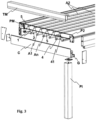
- the present invention relates to a pergola P comprising a support structure S and a foldable shading element O.
- the support structure S comprises a frame C provided with lateral guides G for guiding the foldable shading element O in its folding and unfolding movements.
- the foldable shading element O is made up of blades 1, 2, n articulated together by means of consecutive articulations A1,...., An between the blades 1, 2.
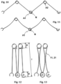
- the blades 1, 2, 3 are profiles of total width I in the transverse direction T, the section of the profile having a central body 11, 21, 31 and two ends 12, 22, 32, 13 , 23, 33 of articulation which have a concave or convex circular envelope section so as to define tubular articulations A1,...., An, the ratio between the diameter D of the circular envelope section and the width total I being greater than 0.1.
- the cylindrical joint is materialized by providing that the ends 12, 22, 32, 13, 23, 33 of the joint have C-shaped sections, and that they can fit together.
- the opening of the C-shaped sections is that which determines the maximum relative opening angle between consecutive slats, and in some examples shown this is an angle between 80 and 90°.
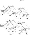
- certain blades 1, 2 comprise at the respective ends of one of the joints AR sliding elements intended to slide through the lateral guides G.
- these elements are wheels R1, R2.
- AT covers which close the ends of the AR joints are provided for fixing the wheels, as can be seen on the figure 8 .
- the articulation ends of the blades can be extruded so as to define ribs N for fixing the wheels, provided for this purpose with an orifice for the threading of the screws fixing VF.
- the blades 1, 2 provided with sliding elements are joined together by means of blades 3 devoid of sliding means, so that the blades 1, 2 provided with sliding elements can form angles between them between 0 and 180°. Therefore, the upper 3 blades can be considered as floating blades.
- the angle formed between the slats of greatest width with the floating slats is 90°, we can ensure that all the slats are coplanar as shown in the figure.
- Figure 14 Namely, even if the relative angle between consecutive slats is only 90°, we can ensure that all of them are on one plane, occupying a minimum thickness when the shading element O is fully unfolded.
- the central body 11, 21, 31 of the blades 1, 2 is planar and joins the articulation ends on the points of tangency with the cylindrical envelope, so that the joints are on the same side as the central body 11, 21 , 31.
- certain blades include a reinforcing rib NR which joins the joint, on the side diametrically opposite the point of junction with the central body 11, 21, 31, to an intermediate point of the central body 11, 21 , 31.
- FIG. 1 Another embodiment can also be designed in which the central body 11, 21 of the blades 1, 2 is curved, which offers greater inertia relative to the general plane of the blade, which for the central body in the case of flat blade is practically zero, so as to present greater resistance to torsion and bending.
- the pergola comprises at least one drive carriage 4 of an end blade L2, the drive carriage being provided with wheels 41, the side profiles G2 being provided with grooves for guiding the wheels 41, as shown in the section of the Figure 9 .
- the pergola is completed by a PM actuation motor, in this tubular case, a pulley P1 actuated by the PM actuation motor, a return pulley P2 and a band 5, belt or chain with links between the actuated pulley P1 by the drive motor M and the return pulley P2, the drive carriage 4 being joined to the band 5, belt or link chain.
- the blades can be made of aluminum, which gives them opacity, resistance to sunlight and adequate rigidity.
- the invention is not limited to the concrete achievements which have been described but also encompasses, for example, the variants which can be produced by those skilled in the art (for example, as to the choice of materials, dimensions , components, configuration, etc.), in what emerges from the claims.
Landscapes
- Engineering & Computer Science (AREA)
- Architecture (AREA)
- Civil Engineering (AREA)
- Structural Engineering (AREA)
- Physics & Mathematics (AREA)
- Electromagnetism (AREA)
- Building Awnings And Sunshades (AREA)
- Wind Motors (AREA)
- Toys (AREA)
Claims (12)
- Pergola (P), die eine Tragstruktur (S) und ein faltbares Beschattungselement (O) umfasst, wobei die Tragstruktur (S) einen Rahmen (C) umfasst, der mit Seitenführungen (G) zur Führung des faltbaren Beschattungselements (O) in seinen Falt- und Entfaltungsbewegungen versehen ist, wobei das faltbare Beschattungselement (O) aus Lamellen (1, 2, 3) gebildet ist, die mittels aufeinanderfolgenden Gelenken (A1, ...., An) zwischen den Lamellen gelenkig miteinander verbunden sind, wobei die Gelenke (A1, ...., An) in der Längsrichtung des Beschattungselements (O) verlaufen, wobei eine Längsrichtung (L) parallel zur Lamelle (1, 2, 3) und zur Falt- und Entfaltungsrichtung, eine Querrichtung (T) und eine Richtung senkrecht (V) zur Längsrichtung (L) und Querrichtung (T), die der Dickenrichtung (V) der Lamelle (1, 2, 3) entspricht, zwischen den Lamellen definiert sind, und indem die Lamellen (1, 2, 3) Profile mit einer Gesamtbreite (I) in der Querrichtung (T) sind, wobei der Abschnitt des Profils einen zentralen Körper (11, 21, 31) und zwei Gelenkenden (12, 22, 32, 13, 23, 33) hat, die einen konkaven oder konvexen Kreismantelabschnitt haben, so dass sie röhrenförmige Gelenke (A1,..., An) bilden, wobei das Verhältnis zwischen dem Durchmesser (D) des Kreismantelabschnitts und der Gesamtbreite (I) größer als 0,1 ist, dadurch gekennzeichnet, dass bestimmte Klingen (1, 2) der Klingen (1, 2, 3) an den jeweiligen Enden von einem der Gelenke (AR) Gleitelemente umfassen, die dazu bestimmt sind, durch die Seitenführungen (G) zu gleiten, die Gleitelemente Räder (R1, R2) sind und davon alle besagten Klingen (1, 2) mit Ausnahme der Endklinge (L1) mit solchen Gleitelementen (R1, R2) versehen sind.
- Pergola (P) nach Anspruch 1, wobei das Verhältnis zwischen dem Durchmesser (D) des Kreismantelabschnitts und der Gesamtbreite (I) größer als 0,15 ist.
- Pergola (P) nach Anspruch 1, wobei die Gesamtbreite (I) zwischen 14 und 16 cm liegt und der Durchmesser (D) des Kreismantelabschnitts zwischen 2 und 2,5 cm liegt.
- Pergola (P) nach Anspruch 3, wobei die Gesamtbreite (I) 153 mm ist und der Durchmesser (D) des Kreismantelabschnitts 23 mm ist, so dass die beiden Gelenke einer Lamelle (1, 2, 3) 30 % der Gesamtbreite (I) ausmachen.
- Pergola (P) nach einem der vorhergehenden Ansprüche, wobei die Enden (12, 22, 32, 13, 23, 33) der Gelenke C-förmige Abschnitte bilden.
- Pergola (P) nach dem vorhergehenden Anspruch, wobei die Öffnung der C-förmigen Abschnitte einem Winkel zwischen 80 und 90° unterliegt.
- Pergola (P) nach Anspruch 1, bei der die mit Gleitelementen versehenen Lamellen (1, 2) mittels Lamellen (3) ohne Gleitelemente verbunden sind, so dass die mit Gleitelementen versehenen Lamellen (1, 2) untereinander Winkel zwischen 0 und 180° bilden können.
- Pergola (P) nach einem der vorhergehenden Ansprüche, wobei der zentrale Körper (11, 21, 31) der Lamellen (1, 2) eben ist und die Gelenkenden an den Tangentenpunkten mit dem zylindrischen Mantel verbindet, so dass die Gelenke auf der gleichen Seite wie der zentrale Körper (11, 21, 31) sind.
- Pergola (P) nach Anspruch 8, wobei bestimmte Lamellen eine Verstärkungsrippe (NR) umfassen, die das Gelenk auf der Seite, die dem Verbindungspunkt mit dem zentralen Körper (11, 21, 31) diametral gegenüberliegt, mit einem Zwischenpunkt des zentralen Körpers (11, 21, 31) verbindet.
- Pergola nach einem der Ansprüche 1 bis 7, wobei der zentrale Körper (11, 21) der Lamellen (1, 2) gebogen ist.
- Pergola nach einem der vorhergehenden Ansprüche, die mindestens einen Antriebsschlitten (4) einer Endlamelle (L2) umfasst, wobei der Antriebsschlitten mit Rädern (41) versehen ist und die Seitenprofile mit Nuten (G2) zur Führung der Räder (41) versehen sind.
- Pergola nach Anspruch 11, die einen Antriebsmotor (PM), eine von dem Antriebsmotor (PM) angetriebene Riemenscheibe (P1), eine Umlenkrolle (P2) und ein Band (5), einen Riemen oder eine Gliederkette zwischen der von dem Antriebsmotor (M) angetriebenen Riemenscheibe (P1) und der Umlenkrolle (P2) umfasst, wobei der Antriebsschlitten (4) mit dem Band (5), dem Riemen oder der Gliederkette verbunden ist.
Applications Claiming Priority (1)
| Application Number | Priority Date | Filing Date | Title |
|---|---|---|---|
| ES201931225U ES1234507Y (es) | 2019-07-17 | 2019-07-17 | Pergola que comprende una estructura de soporte y un elementode sombreado plegable |
Publications (3)
| Publication Number | Publication Date |
|---|---|
| EP3767049A1 EP3767049A1 (de) | 2021-01-20 |
| EP3767049C0 EP3767049C0 (de) | 2024-07-24 |
| EP3767049B1 true EP3767049B1 (de) | 2024-07-24 |
Family
ID=67841871
Family Applications (1)
| Application Number | Title | Priority Date | Filing Date |
|---|---|---|---|
| EP20186474.1A Active EP3767049B1 (de) | 2019-07-17 | 2020-07-17 | Pergola beinhaltend eine tragende struktur und ein faltbares beschattungselement |
Country Status (2)
| Country | Link |
|---|---|
| EP (1) | EP3767049B1 (de) |
| ES (2) | ES1234507Y (de) |
Families Citing this family (3)
| Publication number | Priority date | Publication date | Assignee | Title |
|---|---|---|---|---|
| US10914068B2 (en) * | 2018-02-06 | 2021-02-09 | Infinity Canopy, Inc. | Adjustable awning and retractable canopy system |
| CN113802921A (zh) * | 2020-06-12 | 2021-12-17 | 中标(浙江)智能技术有限公司 | 铰链伸缩遮阳篷 |
| NL2028725B1 (nl) * | 2021-07-14 | 2023-01-20 | Alcre Best B V | Terrasoverkapping |
Family Cites Families (4)
| Publication number | Priority date | Publication date | Assignee | Title |
|---|---|---|---|---|
| DE3403602A1 (de) * | 1984-02-02 | 1985-08-08 | Helmut 4920 Lemgo Hebrok | Dach, insbesondere terrassendach |
| FR2608192B1 (fr) * | 1986-12-12 | 1992-04-30 | Accoplas Fermetures | Couverture repliable pour veranda ou abri similaire |
| DE3801586A1 (de) * | 1988-01-21 | 1989-08-03 | Helmut Hebrok | Dach, insbesondere terrassendach |
| FR3028539B1 (fr) * | 2014-11-17 | 2016-11-25 | Sarl Alpha Concept | Lame orientable pour toiture exterieure et un dispositif de toiture exterieure muni desdites lames |
-
2019
- 2019-07-17 ES ES201931225U patent/ES1234507Y/es not_active Expired - Fee Related
-
2020
- 2020-07-17 ES ES20186474T patent/ES2998116T3/es active Active
- 2020-07-17 EP EP20186474.1A patent/EP3767049B1/de active Active
Also Published As
| Publication number | Publication date |
|---|---|
| ES1234507Y (es) | 2019-12-05 |
| ES2998116T3 (en) | 2025-02-19 |
| EP3767049C0 (de) | 2024-07-24 |
| EP3767049A1 (de) | 2021-01-20 |
| ES1234507U (es) | 2019-09-11 |
Similar Documents
| Publication | Publication Date | Title |
|---|---|---|
| EP2486199B1 (de) | Zusammenklappbarer gitterträger, ausleger und konstruktion mit einem derartigen träger | |
| EP3767049A1 (de) | Pergola beinhaltend eine tragende struktur und ein faltbares beschattungselement | |
| FR2947845A1 (fr) | Installation a lames orientables formant un toit de protection s'ouvrant et se fermant | |
| EP2472023B1 (de) | Abdeckungsvorrichtung, die variable Verdunkelungsmittel umfasst, und Schutzraum mit einer solchen Abdeckung | |
| EP2803778A2 (de) | Dach mit drehbaren Lamellen | |
| EP2817463A1 (de) | Abdeckungsvorrichtung mit gleitenden abdeckelementen | |
| FR2860055A1 (fr) | Joint perimetrique tubulaire a monter sur le rebord d'encadrement d'une ouverture, notamment de carrosserie automobile | |
| EP0207040A1 (de) | Vorrichtung zum Schützen von Glasbauten gegen Sonnenstrahlen | |
| FR2728429A1 (fr) | Tremie pour une moissonneuse batteuse | |
| EP0774032A1 (de) | Variabel gestaltete treppe | |
| FR3028539A1 (fr) | Lame orientable pour toiture exterieure et un dispositif de toiture exterieure muni desdites lames | |
| EP3301240A1 (de) | Demontierbarer pergola-satz | |
| EP2048320B1 (de) | Rollladen beinhaltend einen Behang für ein Abdecksystem mit verstellbaren Lamellen | |
| EP1709259B1 (de) | Klappbare Stufenvorrichtung in Form einer Treppe oder Leiter | |
| FR2529928A1 (fr) | Batiment modulaire pliable | |
| EP0903460A1 (de) | Faltbare Jalousie mit Gelenk | |
| FR2973346A1 (fr) | Structure pliable/deployable a deploiement spontane et verrouillage spontane a l'etat deploye | |
| FR2956692A1 (fr) | Dispositif d'occultation. | |
| EP0323940A1 (de) | Schutzschirm | |
| EP2146044B1 (de) | Panzer einer Verdeckungsvorrichtung, insbesondere eines Rollladens | |
| EP1405964B1 (de) | Aufrollbare Beckenabdeckung | |
| FR2781007A1 (fr) | Brise-soleil a lames modulaires | |
| FR2516585A1 (fr) | Huisserie metallique en tole pliee assemblee par equerres | |
| WO2011114034A1 (fr) | Dispositif d'abri | |
| EP2103467A1 (de) | Öffenbares Verdeck |
Legal Events
| Date | Code | Title | Description |
|---|---|---|---|
| PUAI | Public reference made under article 153(3) epc to a published international application that has entered the european phase |
Free format text: ORIGINAL CODE: 0009012 |
|
| STAA | Information on the status of an ep patent application or granted ep patent |
Free format text: STATUS: THE APPLICATION HAS BEEN PUBLISHED |
|
| AK | Designated contracting states |
Kind code of ref document: A1 Designated state(s): AL AT BE BG CH CY CZ DE DK EE ES FI FR GB GR HR HU IE IS IT LI LT LU LV MC MK MT NL NO PL PT RO RS SE SI SK SM TR |
|
| AX | Request for extension of the european patent |
Extension state: BA ME |
|
| STAA | Information on the status of an ep patent application or granted ep patent |
Free format text: STATUS: REQUEST FOR EXAMINATION WAS MADE |
|
| 17P | Request for examination filed |
Effective date: 20210720 |
|
| RBV | Designated contracting states (corrected) |
Designated state(s): AL AT BE BG CH CY CZ DE DK EE ES FI FR GB GR HR HU IE IS IT LI LT LU LV MC MK MT NL NO PL PT RO RS SE SI SK SM TR |
|
| STAA | Information on the status of an ep patent application or granted ep patent |
Free format text: STATUS: EXAMINATION IS IN PROGRESS |
|
| 17Q | First examination report despatched |
Effective date: 20221222 |
|
| GRAP | Despatch of communication of intention to grant a patent |
Free format text: ORIGINAL CODE: EPIDOSNIGR1 |
|
| STAA | Information on the status of an ep patent application or granted ep patent |
Free format text: STATUS: GRANT OF PATENT IS INTENDED |
|
| INTG | Intention to grant announced |
Effective date: 20240214 |
|
| GRAS | Grant fee paid |
Free format text: ORIGINAL CODE: EPIDOSNIGR3 |
|
| GRAA | (expected) grant |
Free format text: ORIGINAL CODE: 0009210 |
|
| STAA | Information on the status of an ep patent application or granted ep patent |
Free format text: STATUS: THE PATENT HAS BEEN GRANTED |
|
| AK | Designated contracting states |
Kind code of ref document: B1 Designated state(s): AL AT BE BG CH CY CZ DE DK EE ES FI FR GB GR HR HU IE IS IT LI LT LU LV MC MK MT NL NO PL PT RO RS SE SI SK SM TR |
|
| REG | Reference to a national code |
Ref country code: GB Ref legal event code: FG4D Free format text: NOT ENGLISH |
|
| REG | Reference to a national code |
Ref country code: CH Ref legal event code: EP |
|
| REG | Reference to a national code |
Ref country code: IE Ref legal event code: FG4D Free format text: LANGUAGE OF EP DOCUMENT: FRENCH Ref country code: DE Ref legal event code: R096 Ref document number: 602020034378 Country of ref document: DE |
|
| U01 | Request for unitary effect filed |
Effective date: 20240823 |
|
| U07 | Unitary effect registered |
Designated state(s): AT BE BG DE DK EE FI FR IT LT LU LV MT NL PT RO SE SI Effective date: 20240902 |
|
| PG25 | Lapsed in a contracting state [announced via postgrant information from national office to epo] |
Ref country code: NO Free format text: LAPSE BECAUSE OF FAILURE TO SUBMIT A TRANSLATION OF THE DESCRIPTION OR TO PAY THE FEE WITHIN THE PRESCRIBED TIME-LIMIT Effective date: 20241024 |
|
| PG25 | Lapsed in a contracting state [announced via postgrant information from national office to epo] |
Ref country code: GR Free format text: LAPSE BECAUSE OF FAILURE TO SUBMIT A TRANSLATION OF THE DESCRIPTION OR TO PAY THE FEE WITHIN THE PRESCRIBED TIME-LIMIT Effective date: 20241025 Ref country code: PL Free format text: LAPSE BECAUSE OF FAILURE TO SUBMIT A TRANSLATION OF THE DESCRIPTION OR TO PAY THE FEE WITHIN THE PRESCRIBED TIME-LIMIT Effective date: 20240724 |
|
| PG25 | Lapsed in a contracting state [announced via postgrant information from national office to epo] |
Ref country code: IS Free format text: LAPSE BECAUSE OF FAILURE TO SUBMIT A TRANSLATION OF THE DESCRIPTION OR TO PAY THE FEE WITHIN THE PRESCRIBED TIME-LIMIT Effective date: 20241124 |
|
| PG25 | Lapsed in a contracting state [announced via postgrant information from national office to epo] |
Ref country code: HR Free format text: LAPSE BECAUSE OF FAILURE TO SUBMIT A TRANSLATION OF THE DESCRIPTION OR TO PAY THE FEE WITHIN THE PRESCRIBED TIME-LIMIT Effective date: 20240724 |
|
| PG25 | Lapsed in a contracting state [announced via postgrant information from national office to epo] |
Ref country code: RS Free format text: LAPSE BECAUSE OF FAILURE TO SUBMIT A TRANSLATION OF THE DESCRIPTION OR TO PAY THE FEE WITHIN THE PRESCRIBED TIME-LIMIT Effective date: 20241024 |
|
| PG25 | Lapsed in a contracting state [announced via postgrant information from national office to epo] |
Ref country code: RS Free format text: LAPSE BECAUSE OF FAILURE TO SUBMIT A TRANSLATION OF THE DESCRIPTION OR TO PAY THE FEE WITHIN THE PRESCRIBED TIME-LIMIT Effective date: 20241024 Ref country code: PL Free format text: LAPSE BECAUSE OF FAILURE TO SUBMIT A TRANSLATION OF THE DESCRIPTION OR TO PAY THE FEE WITHIN THE PRESCRIBED TIME-LIMIT Effective date: 20240724 Ref country code: NO Free format text: LAPSE BECAUSE OF FAILURE TO SUBMIT A TRANSLATION OF THE DESCRIPTION OR TO PAY THE FEE WITHIN THE PRESCRIBED TIME-LIMIT Effective date: 20241024 Ref country code: IS Free format text: LAPSE BECAUSE OF FAILURE TO SUBMIT A TRANSLATION OF THE DESCRIPTION OR TO PAY THE FEE WITHIN THE PRESCRIBED TIME-LIMIT Effective date: 20241124 Ref country code: HR Free format text: LAPSE BECAUSE OF FAILURE TO SUBMIT A TRANSLATION OF THE DESCRIPTION OR TO PAY THE FEE WITHIN THE PRESCRIBED TIME-LIMIT Effective date: 20240724 Ref country code: GR Free format text: LAPSE BECAUSE OF FAILURE TO SUBMIT A TRANSLATION OF THE DESCRIPTION OR TO PAY THE FEE WITHIN THE PRESCRIBED TIME-LIMIT Effective date: 20241025 |
|
| REG | Reference to a national code |
Ref country code: ES Ref legal event code: FG2A Ref document number: 2998116 Country of ref document: ES Kind code of ref document: T3 Effective date: 20250219 |
|
| PG25 | Lapsed in a contracting state [announced via postgrant information from national office to epo] |
Ref country code: SM Free format text: LAPSE BECAUSE OF FAILURE TO SUBMIT A TRANSLATION OF THE DESCRIPTION OR TO PAY THE FEE WITHIN THE PRESCRIBED TIME-LIMIT Effective date: 20240724 |
|
| PG25 | Lapsed in a contracting state [announced via postgrant information from national office to epo] |
Ref country code: CZ Free format text: LAPSE BECAUSE OF FAILURE TO SUBMIT A TRANSLATION OF THE DESCRIPTION OR TO PAY THE FEE WITHIN THE PRESCRIBED TIME-LIMIT Effective date: 20240724 |
|
| PG25 | Lapsed in a contracting state [announced via postgrant information from national office to epo] |
Ref country code: SK Free format text: LAPSE BECAUSE OF FAILURE TO SUBMIT A TRANSLATION OF THE DESCRIPTION OR TO PAY THE FEE WITHIN THE PRESCRIBED TIME-LIMIT Effective date: 20240724 |
|
| PLBE | No opposition filed within time limit |
Free format text: ORIGINAL CODE: 0009261 |
|
| STAA | Information on the status of an ep patent application or granted ep patent |
Free format text: STATUS: NO OPPOSITION FILED WITHIN TIME LIMIT |
|
| 26N | No opposition filed |
Effective date: 20250425 |
|
| U20 | Renewal fee for the european patent with unitary effect paid |
Year of fee payment: 6 Effective date: 20250528 |
|
| PGFP | Annual fee paid to national office [announced via postgrant information from national office to epo] |
Ref country code: ES Payment date: 20250801 Year of fee payment: 6 |
|
| REG | Reference to a national code |
Ref country code: CH Ref legal event code: H13 Free format text: ST27 STATUS EVENT CODE: U-0-0-H10-H13 (AS PROVIDED BY THE NATIONAL OFFICE) Effective date: 20260224 |
|
| GBPC | Gb: european patent ceased through non-payment of renewal fee |
Effective date: 20250717 |
|
| PG25 | Lapsed in a contracting state [announced via postgrant information from national office to epo] |
Ref country code: GB Free format text: LAPSE BECAUSE OF NON-PAYMENT OF DUE FEES Effective date: 20250717 |
|
| PG25 | Lapsed in a contracting state [announced via postgrant information from national office to epo] |
Ref country code: CH Free format text: LAPSE BECAUSE OF NON-PAYMENT OF DUE FEES Effective date: 20250731 |