EP2472074B1 - Dispositif de commande pour reglage de distribution de soupape - Google Patents
Dispositif de commande pour reglage de distribution de soupape Download PDFInfo
- Publication number
- EP2472074B1 EP2472074B1 EP10828149.4A EP10828149A EP2472074B1 EP 2472074 B1 EP2472074 B1 EP 2472074B1 EP 10828149 A EP10828149 A EP 10828149A EP 2472074 B1 EP2472074 B1 EP 2472074B1
- Authority
- EP
- European Patent Office
- Prior art keywords
- phase
- lock
- rotary body
- side rotary
- angle
- Prior art date
- Legal status (The legal status is an assumption and is not a legal conclusion. Google has not performed a legal analysis and makes no representation as to the accuracy of the status listed.)
- Active
Links
Images





Classifications
-
- F—MECHANICAL ENGINEERING; LIGHTING; HEATING; WEAPONS; BLASTING
- F01—MACHINES OR ENGINES IN GENERAL; ENGINE PLANTS IN GENERAL; STEAM ENGINES
- F01L—CYCLICALLY OPERATING VALVES FOR MACHINES OR ENGINES
- F01L1/00—Valve-gear or valve arrangements, e.g. lift-valve gear
- F01L1/34—Valve-gear or valve arrangements, e.g. lift-valve gear characterised by the provision of means for changing the timing of the valves without changing the duration of opening and without affecting the magnitude of the valve lift
- F01L1/344—Valve-gear or valve arrangements, e.g. lift-valve gear characterised by the provision of means for changing the timing of the valves without changing the duration of opening and without affecting the magnitude of the valve lift changing the angular relationship between crankshaft and camshaft, e.g. using helicoidal gear
- F01L1/3442—Valve-gear or valve arrangements, e.g. lift-valve gear characterised by the provision of means for changing the timing of the valves without changing the duration of opening and without affecting the magnitude of the valve lift changing the angular relationship between crankshaft and camshaft, e.g. using helicoidal gear using hydraulic chambers with variable volume to transmit the rotating force
-
- F—MECHANICAL ENGINEERING; LIGHTING; HEATING; WEAPONS; BLASTING
- F01—MACHINES OR ENGINES IN GENERAL; ENGINE PLANTS IN GENERAL; STEAM ENGINES
- F01L—CYCLICALLY OPERATING VALVES FOR MACHINES OR ENGINES
- F01L1/00—Valve-gear or valve arrangements, e.g. lift-valve gear
- F01L1/34—Valve-gear or valve arrangements, e.g. lift-valve gear characterised by the provision of means for changing the timing of the valves without changing the duration of opening and without affecting the magnitude of the valve lift
- F01L1/344—Valve-gear or valve arrangements, e.g. lift-valve gear characterised by the provision of means for changing the timing of the valves without changing the duration of opening and without affecting the magnitude of the valve lift changing the angular relationship between crankshaft and camshaft, e.g. using helicoidal gear
- F01L1/3442—Valve-gear or valve arrangements, e.g. lift-valve gear characterised by the provision of means for changing the timing of the valves without changing the duration of opening and without affecting the magnitude of the valve lift changing the angular relationship between crankshaft and camshaft, e.g. using helicoidal gear using hydraulic chambers with variable volume to transmit the rotating force
- F01L2001/3445—Details relating to the hydraulic means for changing the angular relationship
- F01L2001/34453—Locking means between driving and driven members
- F01L2001/34463—Locking position intermediate between most retarded and most advanced positions
-
- F—MECHANICAL ENGINEERING; LIGHTING; HEATING; WEAPONS; BLASTING
- F01—MACHINES OR ENGINES IN GENERAL; ENGINE PLANTS IN GENERAL; STEAM ENGINES
- F01L—CYCLICALLY OPERATING VALVES FOR MACHINES OR ENGINES
- F01L1/00—Valve-gear or valve arrangements, e.g. lift-valve gear
- F01L1/34—Valve-gear or valve arrangements, e.g. lift-valve gear characterised by the provision of means for changing the timing of the valves without changing the duration of opening and without affecting the magnitude of the valve lift
- F01L1/344—Valve-gear or valve arrangements, e.g. lift-valve gear characterised by the provision of means for changing the timing of the valves without changing the duration of opening and without affecting the magnitude of the valve lift changing the angular relationship between crankshaft and camshaft, e.g. using helicoidal gear
- F01L1/3442—Valve-gear or valve arrangements, e.g. lift-valve gear characterised by the provision of means for changing the timing of the valves without changing the duration of opening and without affecting the magnitude of the valve lift changing the angular relationship between crankshaft and camshaft, e.g. using helicoidal gear using hydraulic chambers with variable volume to transmit the rotating force
- F01L2001/3445—Details relating to the hydraulic means for changing the angular relationship
- F01L2001/34453—Locking means between driving and driven members
- F01L2001/34466—Locking means between driving and driven members with multiple locking devices
-
- F—MECHANICAL ENGINEERING; LIGHTING; HEATING; WEAPONS; BLASTING
- F01—MACHINES OR ENGINES IN GENERAL; ENGINE PLANTS IN GENERAL; STEAM ENGINES
- F01L—CYCLICALLY OPERATING VALVES FOR MACHINES OR ENGINES
- F01L1/00—Valve-gear or valve arrangements, e.g. lift-valve gear
- F01L1/34—Valve-gear or valve arrangements, e.g. lift-valve gear characterised by the provision of means for changing the timing of the valves without changing the duration of opening and without affecting the magnitude of the valve lift
- F01L1/344—Valve-gear or valve arrangements, e.g. lift-valve gear characterised by the provision of means for changing the timing of the valves without changing the duration of opening and without affecting the magnitude of the valve lift changing the angular relationship between crankshaft and camshaft, e.g. using helicoidal gear
- F01L1/3442—Valve-gear or valve arrangements, e.g. lift-valve gear characterised by the provision of means for changing the timing of the valves without changing the duration of opening and without affecting the magnitude of the valve lift changing the angular relationship between crankshaft and camshaft, e.g. using helicoidal gear using hydraulic chambers with variable volume to transmit the rotating force
- F01L2001/3445—Details relating to the hydraulic means for changing the angular relationship
- F01L2001/34453—Locking means between driving and driven members
- F01L2001/34473—Lock movement perpendicular to camshaft axis
-
- F—MECHANICAL ENGINEERING; LIGHTING; HEATING; WEAPONS; BLASTING
- F01—MACHINES OR ENGINES IN GENERAL; ENGINE PLANTS IN GENERAL; STEAM ENGINES
- F01L—CYCLICALLY OPERATING VALVES FOR MACHINES OR ENGINES
- F01L1/00—Valve-gear or valve arrangements, e.g. lift-valve gear
- F01L1/34—Valve-gear or valve arrangements, e.g. lift-valve gear characterised by the provision of means for changing the timing of the valves without changing the duration of opening and without affecting the magnitude of the valve lift
- F01L1/344—Valve-gear or valve arrangements, e.g. lift-valve gear characterised by the provision of means for changing the timing of the valves without changing the duration of opening and without affecting the magnitude of the valve lift changing the angular relationship between crankshaft and camshaft, e.g. using helicoidal gear
- F01L1/3442—Valve-gear or valve arrangements, e.g. lift-valve gear characterised by the provision of means for changing the timing of the valves without changing the duration of opening and without affecting the magnitude of the valve lift changing the angular relationship between crankshaft and camshaft, e.g. using helicoidal gear using hydraulic chambers with variable volume to transmit the rotating force
- F01L2001/3445—Details relating to the hydraulic means for changing the angular relationship
- F01L2001/34453—Locking means between driving and driven members
- F01L2001/34476—Restrict range locking means
-
- F—MECHANICAL ENGINEERING; LIGHTING; HEATING; WEAPONS; BLASTING
- F01—MACHINES OR ENGINES IN GENERAL; ENGINE PLANTS IN GENERAL; STEAM ENGINES
- F01L—CYCLICALLY OPERATING VALVES FOR MACHINES OR ENGINES
- F01L1/00—Valve-gear or valve arrangements, e.g. lift-valve gear
- F01L1/34—Valve-gear or valve arrangements, e.g. lift-valve gear characterised by the provision of means for changing the timing of the valves without changing the duration of opening and without affecting the magnitude of the valve lift
- F01L1/344—Valve-gear or valve arrangements, e.g. lift-valve gear characterised by the provision of means for changing the timing of the valves without changing the duration of opening and without affecting the magnitude of the valve lift changing the angular relationship between crankshaft and camshaft, e.g. using helicoidal gear
- F01L1/3442—Valve-gear or valve arrangements, e.g. lift-valve gear characterised by the provision of means for changing the timing of the valves without changing the duration of opening and without affecting the magnitude of the valve lift changing the angular relationship between crankshaft and camshaft, e.g. using helicoidal gear using hydraulic chambers with variable volume to transmit the rotating force
- F01L2001/3445—Details relating to the hydraulic means for changing the angular relationship
- F01L2001/34483—Phaser return springs
Definitions
- the present invention relates to a valve timing control apparatus for controlling opening/closing timings of an intake valve and an exhaust valve of an internal combustion engine for use in an automobile.
- valve timing control apparatus in PTL 1, by provision of a torsion spring for applying torque in the advance angle direction to the driven-side rotary body, it is made possible to displace the relative rotational phase in the advance angle direction in a smooth and speedy manner, in spite of the averaged displacement force in the retard angle direction based on torque variations of the camshaft.
- valve timing control apparatus comprises:
- the relative rotational phase can be restrained to two phases of different valve timings such as the first predetermined phase and the second predetermined phase. Therefore, for example, a control arrangement is made possible such that the internal combustion engine can be started in a favorable manner at the first predetermined phase and at the time of the idling operation subsequent thereto, the rotational phase can be retrained to the second predetermined phase. That is, even if there are exerted displacement forces in the retard angle direction and the advance angle direction based on torque variations of the camshaft, there occurs no fluttering of the driven-side rotary body relative to the driving-side rotary body, whether the feeding pressure of the working fluid is high or low. In this way, a favorable startup condition for the internal combustion engine can be obtained and also at the time of a desired operation different from the startup, a stable operation condition can be realized.
- the first lock mechanism and the second lock mechanism respectively include a lock groove formed in either one of the driving-side rotary body and the driven-side rotary body and a lock member provided in the other one of the driving-side rotary body and the driven-side rotary body having the lock groove to be projectable/retractable into/from the lock groove, the lock member being projectable into the lock groove to be retained in this lock groove, thereby to restrain relative rotational movement of the driven-side rotary body relative to the driving-side rotary body.
- the first lock mechanism and the second lock mechanism respectively have such simple arrangement as a lock member and a lock groove, there occurs no complexity of flow passages, or the like. And, it is easy to arrange such that an operation of one lock mechanism does not affect an operation of the other lock mechanism. As a result, individual control of each lock mechanism is made easy and relative rotational phase of the driven-side rotary body can be restrained to phases at desired two positions in a reliable manner. Further, since the restraint of the relative rotational movement of the driven-side rotary body is provided by physical restraint between the lock member and the lock groove, a large restraining force is provided so that the reliability thereof is high also.
- the first lock mechanism and the second lock mechanism respectively include a lock groove formed in either one of the driving-side rotary body and the driven-side rotary body, and the first lock mechanism and the second lock mechanism share a common lock member provided in the other one of the driving-side rotary body and the driven-side rotary body having the respective lock groove to be projectable/retractable into/from the lock groove, the lock member being projectable into the respective lock groove to be retained in this lock groove, thereby to restrain relative rotational movement of the driven-side rotary body relative to the driving-side rotary body to either the first predetermined phase or the second predetermined phase.
- the first lock mechanism and the second lock mechanism respectively have a lock groove and share one same lock member at the same time. Therefore, the arrangement can be made simple and the number of parts can be reduced, thus making manufacturing cost reduction possible. Further, with the sharing of the lock member, sufficient margin of space can be provided in one of the driving-side rotary body and the driven-side rotary body which one rotary body includes the lock member.
- an advance angle passage connecting the fluid control mechanism to the advance angle chamber is connected to the lock groove in the second lock mechanism.
- the lock member when the working fluid is fed to the advance angle passage, the working fluid is fed also to the lock groove of the second lock mechanism. Further, when the working fluid is discharged from the advance angle chamber through the advance angle passage, the working fluid is discharged also from the lock groove of the second lock mechanism. That is, only with execution of control for displacing the relative rotational phase to the most retarded angle phase, the lock member can be caused to protrude into the lock groove in the second lock mechanism. Also, only with execution of control for displacing the relative rotational phase to the advance angle side from the most retarded angle phase, the lock member can be caused to retract from the lock groove in the second lock mechanism.
- control for displacing the relative rotational phase can be operatively linked with the restraint/restraint release of the relative rotational phase by the second lock mechanism required therefor.
- operations of the second lock mechanism according to the control situation of the relative rotational phase can be realized easily.
- the apparatus further comprises one fluid switchover mechanism for switching over the feeding/discharging of the working fluid to/from the first lock mechanism from/to the second lock mechanism.
- the control of the second lock mechanism can be effected, without any dependence on the fluid control mechanism for controlling the relative rotational phase.
- both the first lock mechanism and the second lock mechanism are controlled by one fluid switchover mechanism, there is no increase in the number of components.
- the second predetermined phase is set to a phase on more retarded side than the first predetermined phase.
- the second predetermined phase is set to a phase which is more retard angle side than the first predetermined phase and which is at the most retarded angle phase or adjacent the most retarded angle phase.
- Embodiments wherein the present invention is applied to a valve timing control apparatus for the intake valve side of an automobile engine will be described with reference to Figs. 1 through 7 .
- the automobile engine corresponds to "an internal combustion engine” in the present invention.
- This valve timing control apparatus includes a housing 1 as a "driving-side rotary body" which is rotated in synchronism with a crankshaft of an unillustrated engine, and an inner rotor 2 which is mounted coaxial relative to the housing 1 and acting as a "driven-side rotary body” which is rotated in synchronism with a camshaft 101.
- the camshaft 101 is a rotary shaft for an unillustrated cam which controls opening/closing of the intake valve of the engine.
- the camshaft 101 is rotatably assembled to the cylinder head of the unillustrated engine.
- valve timing control apparatus includes an intermediate lock mechanism 6 as a "first lock mechanism” configured to restrain the relative rotational phase of the inner rotor 2 relative to the housing 1 to a first predetermined phase between a most retarded angle phase and a most advanced angle phase, by restraining the relative rotational movement of the inner rotor 2 relative to the housing 1.
- the valve timing control apparatus still further includes a most retarded angle lock mechanism 7 as a "second lock mechanism” capable of restraining the relative rotational phase to a second predetermined phase different from he first predetermined phase.
- the inner rotor 2 as shown in Fig. 1 , is integrally assembled with the leading end of the camshaft 101.
- the inner rotor 2 is fastened and fixed to the leading end of the camshaft 101 by means of a bolt.
- the housing 1 includes a front plate 11 on the opposite side to the side to which the camshaft 101 is connected, an outer rotor 12 integrally including a timing sprocket 15 and a rear plate 13 to the side the camshaft 101 is connected.
- the outer rotor 12 is mounted externally to the inner rotor 2 and clamped by the front plate 11 and the rear plate 13, with the front plate 11, the outer rotor 12 and the rear plate 13 being fastened together with bolts.
- the outer rotor 12 forms a plurality of projecting portions 14 projecting in the radially inward direction and spaced apart from each other along the rotation direction S.
- the outer rotor 12 and the inner rotor 2 together form fluid pressure chambers 4.
- the projecting portion 14 functions as a "shoe" relative to an outer peripheral face 2a of the inner rotor 2.
- the fluid pressure chambers 4 are provided at three positions. But, the invention is not limited thereto.
- a vane groove 21 is formed in the outer peripheral face 2a at a position thereof facing the fluid pressure chamber 4. And, in this vane groove 21, a vane 22 as a "partitioning portion" is disposed to extend to the radially outer side.
- the fluid pressure chamber 4 is partitioned by the vane 22 into an advance angle chamber 41 and a retard angle chamber 42 along the rotational direction S.
- a spring 23 is disposed between the vane groove 21 and the vane 22 to urge the vane 22 radially outward, thereby to prevent leak of a working fluid between the advance angle chamber 41 and the retard angle chamber 42.
- an advance angle passage 43 is formed in the inner rotor 2 and the camshaft 101.
- a retard angle passage 44 is formed in the inner rotor 2 and the camshaft 101.
- the advance angle passage 43 and the retard angle passage 44 are connected to unillustrated predetermined ports of an OCV 9 as a fluid control mechanism.
- the working fluid is fed/discharged to/from the advance angle chamber 41 and the retard angle chamber 42 or the feeding/discharging amount thereof is maintained, thereby to apply a fluid pressure to the vane 22.
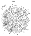
- the advance angle direction is the direction in which the vane 22 effects relative rotational movement relative to the housing 1 to increase the capacity of the advance angle chamber 41 and this direction is indicated by an arrow S1 in Fig. 2 .
- the retard angle direction is the direction in which the capacity of the retard angle chamber 42 is increased and this direction is indicated by an arrow S2 in Fig. 2 .
- the inner rotor 2 can effect smooth relative rotational movement relative to the housing 1 within a predetermined range about the rotational axis X.
- the predetermined range where the housing 1 and the inner rotor 2 can effect relative rotational movement corresponds to the range wherein the vane 22 is displaceable inside the fluid pressure chamber 4.
- the most retarded angle phase is the phase where the capacity of the retard angle chamber 42 is at its maximum.
- the most advanced angle phase is the phase where the capacity of the advance angle chamber 41 is at its maximum.
- the intermediate lock mechanism 6 retains the housing 1 and the inner rotor 2 at predetermined phase positions in a situation when the fluid pressure of the working fluid is unstable immediately after startup of the engine, thereby to restrain the relative rotational phase to an intermediate lock phase as a "first predetermined phase" between the most retarded angle phase and the most advanced angle phase. With this, the rotational phase of the camshaft 101 is maintained appropriate relative to the rotational phase of the crankshaft, thus realizing stable rotation of the engine.
- the intermediate lock phase is set as a phase where the valve opening timing of the unillustrated intake valve is partially overlapped with the valve opening timing of the unillustrated exhaust valve.
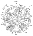
- the intermediate lock mechanism 6, as shown in Fig. 1 and Fig. 2 includes an intermediate lock passage 61, an intermediate lock groove 62, an accommodating portion 63, a plate-like intermediate lock member 64 and a spring 65.
- the intermediate lock passage 61 is formed in the inner rotor 2 and the camshaft 101 and connects the intermediate lock groove 62 with an OSV 10 as "a fluid switchover mechanism" which will be described later.
- OSV 10 an OSV 10 as "a fluid switchover mechanism" which will be described later.
- the intermediate lock groove 62 is formed in the outer peripheral face 2a of the inner rotor 2 and has a fixed width along the relative rotational direction.
- the accommodating portion 63 is formed at two positions in the outer rotor 12.
- Two intermediate lock members 64 are disposed within the respective accommodating portions 63 and can radially project/retract into/from the respective accommodating portions 63.
- the spring 65 is mounted within the accommodating portion 63 and urges each intermediate lock member 64 toward the radially inward direction, that is, toward the intermediate lock groove 62.
- each intermediate lock member 64 When the working fluid is discharged from the intermediate lock groove 62, each intermediate lock member 64 is caused to protrude into the intermediate lock groove 62. As shown in Fig. 2 , when the both intermediate lock members 64 protrude into the intermediate lock groove 62, these respective intermediate lock members 64 will be retained simultaneously at the peripheral opposed ends of the intermediate lock groove 62. As a result, the relative rotational movement of the inner rotor 2 relative to the housing 1 is restrained and the relative rotational phase is restrained to the intermediate lock phase.
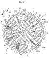
- the working fluid is fed to the intermediate lock groove 62 by controlling the OCV 10, as shown in Fig.
- the both intermediate lock member 64 will be retracted from the intermediate lock groove 62 into the respective accommodating portions 63, thus releasing the restrain of the relative rotational phase, whereby the relative rotational movement of the inner rotor 2 is made possible.
- the intermediate lock phase the condition in which the intermediate lock mechanism 6 restrains the relative rotational phase to the intermediate lock phase.
- an intermediate lock released state the condition where the intermediate lock phase is released.
- any other shape such as a pin-like shape can be employed, instead of the plate-like shape shown in the instant embodiment.
- the most retarded angle lock mechanism 7 maintains the housing 1 and the inner rotor 2 at predetermined relative positions at the time of a low speed rotation such as an idling operation, thereby to restrain the relative rotational phase to the most retarded angle phase as "a second predetermined phase". More particularly, as the inner rotor 2 will not effect relative rotational movement regardless of the displacement force in the retard angle direction or the advance angle direction based on torque variations of the camshaft, so that stable idling operation condition can be realized.
- the most retarded angle phase is the phase where the valve closing timing of the exhaust valve is almost same as the valve opening timing of the intake valve and this is the phase where the idling operation condition is stable. Even when the relative rotational phase is at the most retarded angle phased, the engine can be started.
- the most retarded angle lock mechanism 7 includes a most retarded angle lock passage 71, a most retarded angle lock groove 72, an accommodating portion 73, a plate-like most retarded angle lock member 74 and a spring 75.
- the most retarded angle lock passage 71 acts also as one of the advance angle passages 43 described above and connects the most retarded angle lock groove 72 with the OCV 9. Further, in the outer peripheral face 2a of the inner rotor 2, there is formed an advance angle communication passage 76 as a groove extending along the peripheral direction to the most retarded angle lock groove 72 and one of the vane grooves 21. In response to feeding/discharging of the working fluid to/from the advance angle chamber by the OSV 10, the working fluid is fed/discharged to/from the most retarded angle lock groove 72 as well.
- the accommodating portion 73 is formed in the outer rotor 12.
- the most retarded angle lock member 74 is accommodated in the accommodating portion 73 and can radially protrude/retract into/from the accommodating portion 73.
- the spring 75 is mounted within the accommodating portion 73 and urges the most retarded angle lock member 74 to the radially inward, that is, toward the most retarded angle lock groove 72.
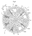
- the most retarded angle lock member 74 When the working fluid is discharged from the most retarded angle groove 72, the most retarded angle lock member 74 is caused to protrude into the most retarded angle lock groove 72. As shown in Fig. 4 , when the most retarded angle lock member 74 protrudes into the most retarded angle lock groove 72, the most retarded angle lock member 74 will be retained in the most retarded angle lock groove 72, whereby relative rotational movement of the inner rotor 2 relative to the housing 1 is restrained and the relative rotational phase is restrained to the most retarded angle phase.
- the most retarded angle lock member 74 When the relative rotational phase is at a phase other than the most retarded angle phase, the most retarded angle lock member 74 is out of positional alignment with the most retarded angle lock groove 72, so the former only comes into slidable contact with the outer peripheral face 2a of the inner rotor 2. At these phases, that is, when the most retarded angle lock member 74 is retracted from the most retarded angle lock groove 72, the most retarded angle lock passage 71 and the advance angle chamber 41 are in constant communication with each other via the advance angle chamber communication passage 76.
- the advance angle chamber communication passage 76 need not be the groove-like, but, though not shown, can be a shape formed by chamfering the outer peripheral corner portion of the inner rotor 2.
- the oil pump 5 as "a working fluid pump”, when driven by the engine, effects feeding of the working oil, an example of the “working fluid”.
- the oil pump 5 is a mechanical hydraulic pump which is driven by receiving the rotational drive force of the crankshaft.
- the oil pump 5, as shown in Fig. 1 draws in an amount of working fluid reserved in an oil pan 5a and discharges this working fluid to the downstream side.
- the discharged working fluid is fed to the fluid pressure chamber 4 via a fluid control mechanism and a fluid switchover mechanism which will be described later.
- the working fluid discharged from the fluid pressure chamber 4 is returned to the oil pan 5a via the fluid control mechanism and the fluid switchover mechanism.
- an arrangement is provided such that an amount of working fluid leaking from the valve timing control apparatus is collected also at the oil pan 5a.
- the valve timing control apparatus includes the electromagnetic type OCV (oil control valve) 9 acting as the "fluid control mechanism” and the electromagnetic type OSV (oil switching valve) 10 acting as the "fluid switchover mechanism".
- the OCV 9 and the OSV 10 are connected respectively to the oil pump 5.
- the OCV 9 it is possible to control feeding, discharging and maintenance of feeding amount of the working fluid to/from/at the advance angle passage 43, the most retarded angle lock passage 71, and the retard angle passage 44.
- switching of the feeding/discharging of the working fluid to/from the intermediate lock passage 61 is possible.
- the OCV 9 is constructed as a spool type, which is operated under control of electric power supply by the ECU 8 (engine control unit). With this OCV 9, controls are made possible such as working oil feeding to the advance angle chamber 41, working oil discharging from the retard angle chamber 42, working oil discharging from the advance angle chamber 41, working oil feeding to the retard angle chamber 42, and blocking of feeding/discharging of working oil to/from the advance angle chamber 41 and the retard angle chamber 42.
- the control of working oil feeding to the advance angle chamber 41 and the working oil discharging from the retard angle chamber 42 is the "advance angle control".
- the vane 22 effects relative rotational movement in the advance angle direction S1 relative to the outer rotor 12, so that the relative rotational phase is displaced toward the advance angle side.
- the control of working oil discharging from the advance angle chamber 41 and the working oil feeding to the retard angle chamber 42 is the "retard angle control". If this retard angle control is effected, the vane 22 effects relative rotational movement in the retard angle direction S2 relative to the outer rotor 12, so that the relative rotational phase is displaced toward the retard angle side. If the control of blocking feeding/discharging of working oil to/from the advance angle chamber 41 and the retard angle chamber 42, the vane 22 does not effect any relative rotational movement, so that the relative rotational phase can be set to any desired phase.
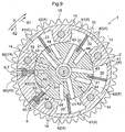
- the advance angle control is effected, working oil is fed to the advance angle passage 43 and the most retarded angle lock passage 71. Under the most retarded angle state, as shown in Fig. 4 , the most retarded angle lock passage 71 is closed by the lock member 74. If the lock member 74 is retracted from the most advanced angle lock groove 72 to provide the most retarded angle lock released state with execution of the advance angle control, the most retarded angle lock passage 71 is opened. With this, through the advance angle chamber communication passage 76, the working oil is fed also to the advance angle chamber 41 adjacent the most retarded angle lock mechanism 7, whereby the inner rotor 2 effects a relative rotational movement toward the advance angle side.
- the instant embodiment it is configured such that in response to power supply (ON) to the OCV 9, the retard angle control is enabled whereas in response to stop (OFF) of power supply to the OCV 9, the advance angle control is enabled.
- the OCV 9 is configured to set the valve opening ratio through adjustment of the duty ratio of electric power to be supplied to an electromagnetic solenoid. With this, fine adjustment of feeding/discharging mount of working oil is made possible.
- crank angle sensor for detecting a rotational angle of the crankshaft of the engine and a camshaft angle sensor for detecting a rotational angle of the camshaft 101.
- the ECU 8 detects a relative rotational phase based on the results of detection by these crank angle sensor and the camshaft angle sensor and determines at which phase the relative rotational phase is currently located. Further, the ECU 8 incorporates signal lines for obtaining ON/OFF information of the ignition key, information from an oil temperature sensor for detecting the oil temperature of the working oil, etc. Also, a memory provided in the ECU 8 stores therein control information of optimum relative rotational phase according to operational conditions of the engine. The ECU 8 controls the relative rotational phase, based on the information of operational conditions (engine rotational speed, cooling water temperature, etc.) and the above-described control information.
- a torsion spring 3 is provided between the inner rotor 2 and the front plate 11.
- the torsion spring 3 urges the inner rotor 2 toward the advance angle side so as to resist the averaged displacement force in the retard angle direction based on torque variation of the camshaft. With this, it is possible to displace the relative rotational phase to the advance angle direction in a smooth and speedy manner.
- the retard angle control will be executed to displace the relative rotational phase to a phase on more retard angle side than the lock phase or as shown in Fig. 5 , the advance angle control will be executed for displacing the relative rotational phase to a phase on more advance angle side than the lock phase or with execution of power supply with duty ratio adjustment, the relative rotational phase will be maintained to a desired phase.
- the most retarded angle locked state is provided. However, since this can be immediately rendered into the most retarded angle lock released state with execution of the advance angle control, there occurs no inconvenience.
- the OSV 10 is rendered into the condition enabling discharging of working oil from the intermediate lock groove 62 in response to power supply thereto and is rendered into the condition enabling feeding of working oil to the intermediate lock groove 62 in response to stop of power supply thereto.
- the invention is not limited thereto.
- the OSV 10 may be alternatively configured such that OSV 10 is rendered into the condition enabling feeding of working oil from the intermediate lock groove 62 in response to power supply thereto and is rendered into the condition enabling discharging of working oil from the intermediate lock groove 62 in response to stop of power supply thereto.
- control operations as shown in Fig. 7 are executed.
- the intermediate locked state shown in Fig. 8 if the power supply to the OSV 10 is stopped, there is provided the intermediate lock released state as shown in Fig. 9 . Thereafter, as long as the stop of the power supply to the OSV 10 is continued, feeding of the working oil to the intermediate lock groove 62 is continued. Hence, the intermediate lock members 64 will not protrude into the intermediate lock groove 62.
- the construction can be simplified and also the number of parts (components) can be reduced, so that manufacturing cost reduction is made possible.
- the intermediate lock member 64 and the most retarded angle lock member 74 there is provided spare space in the outer rotor 12 in the peripheral direction.
- the intermediate locked state Prior to engine startup, the intermediate locked state is provided by the intermediate lock mechanism 6. Hence, in response to an ON operation of the unillustrated ignition key, the engine will be started under the state of relative rotational phase being restrained to this intermediate lock phase (intermediate locked state) and an idling operation is initiated. Incidentally, simultaneously with the ON operation of the ignition key, power supply to the OSV 10 is effected and the intermediate locked state is maintained.
- the OCV 9 enables the retard angle control in response to power supply thereto and enables the advance angle control in response to stop of power supply thereto.
- the invention is not limited thereto.
- the OCV 9 may be alternatively configured such that the advance angle control is enabled in response to power supply thereto and the retard angle control is enabled in response to stop of power supply thereto.
- the present invention may be applied not only to a valve timing control apparatus on the intake side, but also to a valve timing control apparatus on the exhaust side. Further, the invention may be applied to a valve timing control apparatus for an internal combustion engine of an automobile or others.
Landscapes
- Engineering & Computer Science (AREA)
- Mechanical Engineering (AREA)
- General Engineering & Computer Science (AREA)
- Valve Device For Special Equipments (AREA)
Claims (8)
- Dispositif de contrôle du calage des soupapes, comprenant :un corps rotatif côté entraînant (1) apte à être mis en rotation en synchronisme avec un vilebrequin d'un moteur à combustion interne ;un corps rotatif côté entraîné (2) monté coaxialement par rapport au corps rotatif côté entraînant (1) et apte à être mis en rotation en synchronisme avec un arbre à cames d'ouverture/fermeture de soupape (101) du moteur à combustion interne ;une chambre de pression de fluide (4) formée par le corps rotatif côté entraînant (1) et le corps rotatif côté entraîné (2), et divisée en une chambre à angle de retardement (42) et en une chambre à angle d'avance (41) par une portion de division (22) prévue dans au moins l'un parmi le corps rotatif côté entraînant (1) et le corps rotatif côté entraîné (2) ;un mécanisme de contrôle de fluide (9) pour contrôler l'alimentation d'un fluide de fonctionnement par une pompe à fluide de fonctionnement (5) afin d'alimenter le fluide de fonctionnement vers la chambre de pression de fluide (4), et pour contrôler également l'évacuation du fluide de fonctionnement hors de la chambre de pression de fluide (4) ;un premier mécanisme de verrouillage (6) capable de restreindre une phase de rotation relative du corps rotatif côté entraîné (2) par rapport au corps rotatif côté entraînant (1) à une première phase de verrouillage prédéterminée entre une phase d'angle de retardement maximum et une phase d'angle d'avance maximum ; etun deuxième mécanisme de verrouillage (7),caractérisé en ce que
le deuxième mécanisme de verrouillage (7) est capable de restreindre la phase de rotation relative à une deuxième phase de verrouillage prédéterminée différente de la première phase de verrouillage prédéterminée. - Dispositif de contrôle du calage des soupapes selon la revendication 1, dans lequel, au moment de la restriction par le premier mécanisme de verrouillage (6), la restriction de la phase de rotation relative par le deuxième mécanisme de verrouillage (7) est relâchée.
- Dispositif de contrôle du calage des soupapes selon la revendication 1 ou 2, dans lequel le premier mécanisme de verrouillage (6) et le deuxième mécanisme de verrouillage (7) comprennent respectivement :une gorge de verrouillage (62, 72) formée dans l'un parmi le corps rotatif côté entraînant (1) et le corps rotatif côté entraîné (2) ; etun élément de verrouillage (64, 74) prévu dans l'autre parmi le corps rotatif côté entraînant (1) et le corps rotatif côté entraîné (2) comportant la gorge de verrouillage (62, 72) pour faire saillie dans/se rétracter hors de la gorge de verrouillage, l'élément de verrouillage (64, 74) pouvant faire saillie dans la gorge de verrouillage (62, 72) pour être retenu dans cette gorge de verrouillage (62, 72), pour ainsi restreindre le mouvement de rotation relatif du corps rotatif côté entraîné (2) par rapport au corps rotatif côté entraînant (1).
- Dispositif de contrôle du calage des soupapes selon la revendication 1 ou 2, dans lequel le premier mécanisme de verrouillage (6) et le deuxième mécanisme de verrouillage (7) comprennent respectivement une gorge de verrouillage (62) formée dans l'un parmi le corps rotatif côté entraînant (1) et le corps rotatif côté entraîné (2), et
le premier mécanisme de verrouillage (6) et le deuxième mécanisme de verrouillage (7) se partagent un élément de verrouillage commun (64) prévu dans l'autre parmi le corps rotatif côté entraînant (1) et le corps rotatif côté entraîné (2) comportant la gorge de verrouillage (62) respective pour faire saillie dans/se rétracter hors de la gorge de verrouillage (62), l'élément de verrouillage (64) pouvant faire saillie dans la gorge de verrouillage (62) respective pour être retenu dans cette gorge de verrouillage (62), pour ainsi restreindre le mouvement de rotation relatif du corps rotatif côté entraîné (2) par rapport au corps rotatif côté entraînant (1) à la première phase prédéterminée ou à la deuxième phase prédéterminée. - Dispositif de contrôle du calage des soupapes selon la revendication 3 ou 4, dans lequel un passage d'angle d'avance (43) reliant le mécanisme de contrôle de fluide (9) à la chambre d'angle d'avance (41) est relié à la gorge de verrouillage (72) dans le deuxième mécanisme de verrouillage (7).
- Dispositif de contrôle du calage des soupapes selon l'une quelconque des revendications 1-4, comprenant en outre un mécanisme de commutation de fluide (10) pour basculer entre l'alimentation/l'évacuation de fluide de fonctionnement vers le/à partir du premier mécanisme de verrouillage (6) à partir du/vers le deuxième mécanisme de verrouillage (7).
- Dispositif de contrôle du calage des soupapes selon l'une quelconque des revendications 1-6, dans lequel la deuxième phase prédéterminée est réglée sur une phase plus proche du côté retardement que la première phase prédéterminée.
- Dispositif de contrôle du calage des soupapes selon l'une quelconque des revendications 1-6, dans lequel la deuxième phase prédéterminée est réglée sur une phase plus proche du côté angle de retardement que la première phase prédéterminée, située sur la phase d'angle de retardement maximum ou à côté de la phase d'angle de retardement maximum.
Applications Claiming Priority (2)
| Application Number | Priority Date | Filing Date | Title |
|---|---|---|---|
| JP2009253278 | 2009-11-04 | ||
| PCT/JP2010/065501 WO2011055589A1 (fr) | 2009-11-04 | 2010-09-09 | Dispositif de commande pour réglage de distribution de soupape |
Publications (3)
| Publication Number | Publication Date |
|---|---|
| EP2472074A1 EP2472074A1 (fr) | 2012-07-04 |
| EP2472074A4 EP2472074A4 (fr) | 2012-12-12 |
| EP2472074B1 true EP2472074B1 (fr) | 2013-10-23 |
Family
ID=43969829
Family Applications (1)
| Application Number | Title | Priority Date | Filing Date |
|---|---|---|---|
| EP10828149.4A Active EP2472074B1 (fr) | 2009-11-04 | 2010-09-09 | Dispositif de commande pour reglage de distribution de soupape |
Country Status (6)
| Country | Link |
|---|---|
| US (1) | US8820278B2 (fr) |
| EP (1) | EP2472074B1 (fr) |
| JP (1) | JP5582363B2 (fr) |
| CN (1) | CN102597437B (fr) |
| IN (1) | IN2012DN01868A (fr) |
| WO (1) | WO2011055589A1 (fr) |
Families Citing this family (27)
| Publication number | Priority date | Publication date | Assignee | Title |
|---|---|---|---|---|
| DE102008011915A1 (de) * | 2008-02-29 | 2009-09-03 | Schaeffler Kg | Nockenwellenversteller mit Verriegelungseinrichtung |
| JP5029671B2 (ja) * | 2009-10-15 | 2012-09-19 | 株式会社デンソー | バルブタイミング調整装置 |
| JP5763432B2 (ja) * | 2011-06-17 | 2015-08-12 | 日立オートモティブシステムズ株式会社 | 内燃機関のバルブタイミング制御装置 |
| JP5783255B2 (ja) | 2011-09-02 | 2015-09-24 | トヨタ自動車株式会社 | 車両用エンジンの制御装置 |
| JP5739305B2 (ja) * | 2011-10-26 | 2015-06-24 | 日立オートモティブシステムズ株式会社 | 内燃機関のバルブタイミング制御装置 |
| JP5541317B2 (ja) * | 2012-02-08 | 2014-07-09 | 株式会社デンソー | バルブタイミング調整装置 |
| CN103375212B (zh) * | 2012-04-26 | 2016-12-28 | 日立汽车系统株式会社 | 内燃机的可变气门装置 |
| CN103452614B (zh) * | 2012-05-30 | 2016-01-06 | 爱信精机株式会社 | 气门开闭时间控制装置及内燃机控制系统 |
| JP6035880B2 (ja) * | 2012-05-30 | 2016-11-30 | アイシン精機株式会社 | 弁開閉時期制御装置 |
| JP2014034914A (ja) | 2012-08-08 | 2014-02-24 | Aisin Seiki Co Ltd | 弁開閉時期制御装置 |
| JP5966781B2 (ja) | 2012-09-06 | 2016-08-10 | アイシン精機株式会社 | 弁開閉時期制御システム |
| JP2014051919A (ja) * | 2012-09-06 | 2014-03-20 | Aisin Seiki Co Ltd | 弁開閉時期制御装置 |
| JP6007689B2 (ja) * | 2012-09-11 | 2016-10-12 | アイシン精機株式会社 | 弁開閉時期制御装置 |
| DE102012222537B4 (de) * | 2012-12-07 | 2017-05-04 | Schaeffler Technologies AG & Co. KG | Nockenwellenversteller |
| US9856759B2 (en) | 2012-12-07 | 2018-01-02 | Schaeffler Technologies AG & Co. KG | Camshaft adjuster |
| DE102013203955B4 (de) * | 2013-03-08 | 2018-05-30 | Schaeffler Technologies AG & Co. KG | Hydraulische Nockenwellenvorrichtung mit kugelabschnittsartiger Verriegelung |
| JP6171423B2 (ja) * | 2013-03-11 | 2017-08-02 | アイシン精機株式会社 | 弁開閉時期制御装置 |
| JP6225725B2 (ja) * | 2013-03-11 | 2017-11-08 | アイシン精機株式会社 | 弁開閉時期制御装置 |
| DE102013204929A1 (de) * | 2013-03-20 | 2014-09-25 | Schaeffler Technologies Gmbh & Co. Kg | Nockenwellenversteller |
| JP6091277B2 (ja) * | 2013-03-21 | 2017-03-08 | 日立オートモティブシステムズ株式会社 | 内燃機関のバルブタイミング制御装置 |
| JP6127631B2 (ja) * | 2013-03-22 | 2017-05-17 | アイシン精機株式会社 | 内燃機関 |
| WO2014192355A1 (fr) * | 2013-05-30 | 2014-12-04 | アイシン精機株式会社 | Dispositif de commande de moment d'ouverture/fermeture de soupape |
| WO2015015824A1 (fr) | 2013-07-31 | 2015-02-05 | アイシン精機株式会社 | Dispositif de commande pour moteur à combustion interne |
| DE102013219075B4 (de) * | 2013-09-23 | 2020-11-26 | Schaeffler Technologies AG & Co. KG | Multiverriegelung eines Nockenwellenverstellers |
| KR101567225B1 (ko) * | 2014-06-25 | 2015-11-06 | 현대자동차주식회사 | 이원적 중간위상 제어방법을 적용한 중간위상 연속 가변 밸브 제어 시스템 |
| JP6251778B2 (ja) * | 2016-07-04 | 2017-12-20 | 日立オートモティブシステムズ株式会社 | 内燃機関のバルブタイミング制御装置 |
| CN110410168B (zh) * | 2018-04-28 | 2021-07-16 | 联合汽车电子有限公司 | 中间锁止vvt系统的控制系统及控制方法 |
Family Cites Families (23)
| Publication number | Priority date | Publication date | Assignee | Title |
|---|---|---|---|---|
| JPH11280427A (ja) * | 1998-03-31 | 1999-10-12 | Aisin Seiki Co Ltd | 弁開閉時期制御装置 |
| JP3918971B2 (ja) | 1998-04-27 | 2007-05-23 | アイシン精機株式会社 | 弁開閉時期制御装置 |
| DE10064222B4 (de) | 1999-12-24 | 2006-02-09 | Aisin Seiki K.K., Kariya | Verstellbares Ventilsteuersystem |
| JP4389383B2 (ja) | 1999-12-24 | 2009-12-24 | アイシン精機株式会社 | 弁開閉時期制御装置 |
| US6876460B2 (en) * | 2000-01-31 | 2005-04-05 | Canon Kabushiki Kaisha | Image processing apparatus, image processing method and storage medium |
| JP4262873B2 (ja) | 2000-08-18 | 2009-05-13 | 三菱電機株式会社 | 内燃機関のバルブタイミング調整装置 |
| JP2002097911A (ja) * | 2000-09-22 | 2002-04-05 | Aisin Seiki Co Ltd | 弁開閉時期制御装置 |
| JP4465846B2 (ja) | 2000-09-27 | 2010-05-26 | アイシン精機株式会社 | 弁開閉時期制御装置 |
| DE10213831A1 (de) | 2001-03-28 | 2002-11-07 | Denso Corp | Variables Ventilsteuerzeitengerät |
| JP4411814B2 (ja) * | 2001-03-30 | 2010-02-10 | 株式会社デンソー | バルブタイミング調整装置 |
| JP4000522B2 (ja) | 2003-02-26 | 2007-10-31 | アイシン精機株式会社 | 弁開閉時期制御装置 |
| JP2006170026A (ja) * | 2004-12-14 | 2006-06-29 | Aisin Seiki Co Ltd | 内燃機関の弁開閉時期制御装置 |
| JP2006170085A (ja) | 2004-12-16 | 2006-06-29 | Aisin Seiki Co Ltd | 弁開閉時期制御装置及び最低トルクの設定方法 |
| JP4609714B2 (ja) | 2005-05-19 | 2011-01-12 | アイシン精機株式会社 | 弁開閉時期制御装置 |
| JP4320645B2 (ja) * | 2005-05-19 | 2009-08-26 | アイシン精機株式会社 | 弁開閉時期制御装置 |
| DE102005036707A1 (de) | 2005-08-04 | 2007-02-08 | Daimlerchrysler Ag | Nockenwellenstellvorrichtung |
| JP4687964B2 (ja) * | 2005-08-31 | 2011-05-25 | アイシン精機株式会社 | 弁開閉時期制御装置 |
| JP4556137B2 (ja) | 2005-12-05 | 2010-10-06 | アイシン精機株式会社 | 弁開閉時期制御装置 |
| JP4605473B2 (ja) * | 2005-12-27 | 2011-01-05 | アイシン精機株式会社 | 弁開閉時期制御装置 |
| DE102007002137A1 (de) * | 2007-01-10 | 2008-07-17 | Nordex Energy Gmbh | Windenergieanlage mit einer hydraulisch betätigten Rotorbremse |
| JP2009250073A (ja) * | 2008-04-02 | 2009-10-29 | Denso Corp | バルブタイミング調整装置 |
| JP4661902B2 (ja) * | 2008-04-18 | 2011-03-30 | 株式会社デンソー | バルブタイミング調整装置 |
| US8033257B2 (en) | 2008-04-28 | 2011-10-11 | Delphi Technologies, Inc. | Vane-type cam phaser having staged locking pins to assist intermediate position locking |
-
2010
- 2010-09-09 EP EP10828149.4A patent/EP2472074B1/fr active Active
- 2010-09-09 US US13/392,563 patent/US8820278B2/en active Active
- 2010-09-09 WO PCT/JP2010/065501 patent/WO2011055589A1/fr not_active Ceased
- 2010-09-09 JP JP2011539311A patent/JP5582363B2/ja active Active
- 2010-09-09 CN CN201080050133.XA patent/CN102597437B/zh active Active
- 2010-09-09 IN IN1868DEN2012 patent/IN2012DN01868A/en unknown
Also Published As
| Publication number | Publication date |
|---|---|
| EP2472074A1 (fr) | 2012-07-04 |
| EP2472074A4 (fr) | 2012-12-12 |
| JPWO2011055589A1 (ja) | 2013-03-28 |
| CN102597437A (zh) | 2012-07-18 |
| CN102597437B (zh) | 2015-01-28 |
| IN2012DN01868A (fr) | 2015-08-21 |
| WO2011055589A1 (fr) | 2011-05-12 |
| JP5582363B2 (ja) | 2014-09-03 |
| US8820278B2 (en) | 2014-09-02 |
| US20120152190A1 (en) | 2012-06-21 |
Similar Documents
| Publication | Publication Date | Title |
|---|---|---|
| US8820278B2 (en) | Valve timing control apparatus | |
| EP2278130B1 (fr) | Appareil de contrôle de la synchronisation d'une soupape variable | |
| CN102639823B (zh) | 阀开闭定时控制装置 | |
| EP2863024B1 (fr) | Unité de commande de réglage de distribution | |
| US8919310B2 (en) | Valve open/close timing control device | |
| JP2010209780A (ja) | 内燃機関の可変動弁機構 | |
| JP6036600B2 (ja) | 弁開閉時期制御装置 | |
| JP6075449B2 (ja) | 弁開閉時期制御装置 | |
| JP5979093B2 (ja) | 弁開閉時期制御装置 | |
| JP6035880B2 (ja) | 弁開閉時期制御装置 | |
| JP6225725B2 (ja) | 弁開閉時期制御装置 | |
| JP4478855B2 (ja) | 弁開閉時期制御装置 | |
| JP6171423B2 (ja) | 弁開閉時期制御装置 | |
| JP2010169009A (ja) | 弁開閉時期制御装置 |
Legal Events
| Date | Code | Title | Description |
|---|---|---|---|
| PUAI | Public reference made under article 153(3) epc to a published international application that has entered the european phase |
Free format text: ORIGINAL CODE: 0009012 |
|
| 17P | Request for examination filed |
Effective date: 20120329 |
|
| AK | Designated contracting states |
Kind code of ref document: A1 Designated state(s): AL AT BE BG CH CY CZ DE DK EE ES FI FR GB GR HR HU IE IS IT LI LT LU LV MC MK MT NL NO PL PT RO SE SI SK SM TR |
|
| A4 | Supplementary search report drawn up and despatched |
Effective date: 20121108 |
|
| RIC1 | Information provided on ipc code assigned before grant |
Ipc: F01L 1/34 20060101AFI20121102BHEP Ipc: F01L 1/344 20060101ALI20121102BHEP |
|
| DAX | Request for extension of the european patent (deleted) | ||
| GRAP | Despatch of communication of intention to grant a patent |
Free format text: ORIGINAL CODE: EPIDOSNIGR1 |
|
| INTG | Intention to grant announced |
Effective date: 20130624 |
|
| GRAS | Grant fee paid |
Free format text: ORIGINAL CODE: EPIDOSNIGR3 |
|
| GRAA | (expected) grant |
Free format text: ORIGINAL CODE: 0009210 |
|
| AK | Designated contracting states |
Kind code of ref document: B1 Designated state(s): AL AT BE BG CH CY CZ DE DK EE ES FI FR GB GR HR HU IE IS IT LI LT LU LV MC MK MT NL NO PL PT RO SE SI SK SM TR |
|
| REG | Reference to a national code |
Ref country code: GB Ref legal event code: FG4D |
|
| REG | Reference to a national code |
Ref country code: CH Ref legal event code: EP |
|
| REG | Reference to a national code |
Ref country code: AT Ref legal event code: REF Ref document number: 637738 Country of ref document: AT Kind code of ref document: T Effective date: 20131115 |
|
| REG | Reference to a national code |
Ref country code: IE Ref legal event code: FG4D |
|
| REG | Reference to a national code |
Ref country code: DE Ref legal event code: R096 Ref document number: 602010011268 Country of ref document: DE Effective date: 20131219 |
|
| REG | Reference to a national code |
Ref country code: NL Ref legal event code: VDEP Effective date: 20131023 |
|
| REG | Reference to a national code |
Ref country code: AT Ref legal event code: MK05 Ref document number: 637738 Country of ref document: AT Kind code of ref document: T Effective date: 20131023 |
|
| REG | Reference to a national code |
Ref country code: LT Ref legal event code: MG4D |
|
| PG25 | Lapsed in a contracting state [announced via postgrant information from national office to epo] |
Ref country code: LT Free format text: LAPSE BECAUSE OF FAILURE TO SUBMIT A TRANSLATION OF THE DESCRIPTION OR TO PAY THE FEE WITHIN THE PRESCRIBED TIME-LIMIT Effective date: 20131023 Ref country code: SE Free format text: LAPSE BECAUSE OF FAILURE TO SUBMIT A TRANSLATION OF THE DESCRIPTION OR TO PAY THE FEE WITHIN THE PRESCRIBED TIME-LIMIT Effective date: 20131023 Ref country code: FI Free format text: LAPSE BECAUSE OF FAILURE TO SUBMIT A TRANSLATION OF THE DESCRIPTION OR TO PAY THE FEE WITHIN THE PRESCRIBED TIME-LIMIT Effective date: 20131023 Ref country code: HR Free format text: LAPSE BECAUSE OF FAILURE TO SUBMIT A TRANSLATION OF THE DESCRIPTION OR TO PAY THE FEE WITHIN THE PRESCRIBED TIME-LIMIT Effective date: 20131023 Ref country code: IS Free format text: LAPSE BECAUSE OF FAILURE TO SUBMIT A TRANSLATION OF THE DESCRIPTION OR TO PAY THE FEE WITHIN THE PRESCRIBED TIME-LIMIT Effective date: 20140223 Ref country code: NL Free format text: LAPSE BECAUSE OF FAILURE TO SUBMIT A TRANSLATION OF THE DESCRIPTION OR TO PAY THE FEE WITHIN THE PRESCRIBED TIME-LIMIT Effective date: 20131023 Ref country code: BE Free format text: LAPSE BECAUSE OF FAILURE TO SUBMIT A TRANSLATION OF THE DESCRIPTION OR TO PAY THE FEE WITHIN THE PRESCRIBED TIME-LIMIT Effective date: 20131023 Ref country code: NO Free format text: LAPSE BECAUSE OF FAILURE TO SUBMIT A TRANSLATION OF THE DESCRIPTION OR TO PAY THE FEE WITHIN THE PRESCRIBED TIME-LIMIT Effective date: 20140123 |
|
| PG25 | Lapsed in a contracting state [announced via postgrant information from national office to epo] |
Ref country code: LV Free format text: LAPSE BECAUSE OF FAILURE TO SUBMIT A TRANSLATION OF THE DESCRIPTION OR TO PAY THE FEE WITHIN THE PRESCRIBED TIME-LIMIT Effective date: 20131023 Ref country code: AT Free format text: LAPSE BECAUSE OF FAILURE TO SUBMIT A TRANSLATION OF THE DESCRIPTION OR TO PAY THE FEE WITHIN THE PRESCRIBED TIME-LIMIT Effective date: 20131023 Ref country code: CY Free format text: LAPSE BECAUSE OF FAILURE TO SUBMIT A TRANSLATION OF THE DESCRIPTION OR TO PAY THE FEE WITHIN THE PRESCRIBED TIME-LIMIT Effective date: 20131023 Ref country code: ES Free format text: LAPSE BECAUSE OF FAILURE TO SUBMIT A TRANSLATION OF THE DESCRIPTION OR TO PAY THE FEE WITHIN THE PRESCRIBED TIME-LIMIT Effective date: 20131023 |
|
| PG25 | Lapsed in a contracting state [announced via postgrant information from national office to epo] |
Ref country code: PT Free format text: LAPSE BECAUSE OF FAILURE TO SUBMIT A TRANSLATION OF THE DESCRIPTION OR TO PAY THE FEE WITHIN THE PRESCRIBED TIME-LIMIT Effective date: 20140224 |
|
| REG | Reference to a national code |
Ref country code: DE Ref legal event code: R097 Ref document number: 602010011268 Country of ref document: DE |
|
| PG25 | Lapsed in a contracting state [announced via postgrant information from national office to epo] |
Ref country code: EE Free format text: LAPSE BECAUSE OF FAILURE TO SUBMIT A TRANSLATION OF THE DESCRIPTION OR TO PAY THE FEE WITHIN THE PRESCRIBED TIME-LIMIT Effective date: 20131023 |
|
| PG25 | Lapsed in a contracting state [announced via postgrant information from national office to epo] |
Ref country code: PL Free format text: LAPSE BECAUSE OF FAILURE TO SUBMIT A TRANSLATION OF THE DESCRIPTION OR TO PAY THE FEE WITHIN THE PRESCRIBED TIME-LIMIT Effective date: 20131023 Ref country code: SK Free format text: LAPSE BECAUSE OF FAILURE TO SUBMIT A TRANSLATION OF THE DESCRIPTION OR TO PAY THE FEE WITHIN THE PRESCRIBED TIME-LIMIT Effective date: 20131023 Ref country code: IT Free format text: LAPSE BECAUSE OF FAILURE TO SUBMIT A TRANSLATION OF THE DESCRIPTION OR TO PAY THE FEE WITHIN THE PRESCRIBED TIME-LIMIT Effective date: 20131023 Ref country code: RO Free format text: LAPSE BECAUSE OF FAILURE TO SUBMIT A TRANSLATION OF THE DESCRIPTION OR TO PAY THE FEE WITHIN THE PRESCRIBED TIME-LIMIT Effective date: 20131023 |
|
| PLBE | No opposition filed within time limit |
Free format text: ORIGINAL CODE: 0009261 |
|
| STAA | Information on the status of an ep patent application or granted ep patent |
Free format text: STATUS: NO OPPOSITION FILED WITHIN TIME LIMIT |
|
| PG25 | Lapsed in a contracting state [announced via postgrant information from national office to epo] |
Ref country code: DK Free format text: LAPSE BECAUSE OF FAILURE TO SUBMIT A TRANSLATION OF THE DESCRIPTION OR TO PAY THE FEE WITHIN THE PRESCRIBED TIME-LIMIT Effective date: 20131023 |
|
| 26N | No opposition filed |
Effective date: 20140724 |
|
| REG | Reference to a national code |
Ref country code: DE Ref legal event code: R097 Ref document number: 602010011268 Country of ref document: DE Effective date: 20140724 |
|
| PG25 | Lapsed in a contracting state [announced via postgrant information from national office to epo] |
Ref country code: SI Free format text: LAPSE BECAUSE OF FAILURE TO SUBMIT A TRANSLATION OF THE DESCRIPTION OR TO PAY THE FEE WITHIN THE PRESCRIBED TIME-LIMIT Effective date: 20131023 |
|
| PG25 | Lapsed in a contracting state [announced via postgrant information from national office to epo] |
Ref country code: MC Free format text: LAPSE BECAUSE OF FAILURE TO SUBMIT A TRANSLATION OF THE DESCRIPTION OR TO PAY THE FEE WITHIN THE PRESCRIBED TIME-LIMIT Effective date: 20131023 Ref country code: LU Free format text: LAPSE BECAUSE OF FAILURE TO SUBMIT A TRANSLATION OF THE DESCRIPTION OR TO PAY THE FEE WITHIN THE PRESCRIBED TIME-LIMIT Effective date: 20140909 |
|
| REG | Reference to a national code |
Ref country code: CH Ref legal event code: PL |
|
| GBPC | Gb: european patent ceased through non-payment of renewal fee |
Effective date: 20140909 |
|
| REG | Reference to a national code |
Ref country code: IE Ref legal event code: MM4A |
|
| PG25 | Lapsed in a contracting state [announced via postgrant information from national office to epo] |
Ref country code: CH Free format text: LAPSE BECAUSE OF NON-PAYMENT OF DUE FEES Effective date: 20140930 Ref country code: GB Free format text: LAPSE BECAUSE OF NON-PAYMENT OF DUE FEES Effective date: 20140909 Ref country code: LI Free format text: LAPSE BECAUSE OF NON-PAYMENT OF DUE FEES Effective date: 20140930 |
|
| PG25 | Lapsed in a contracting state [announced via postgrant information from national office to epo] |
Ref country code: IE Free format text: LAPSE BECAUSE OF NON-PAYMENT OF DUE FEES Effective date: 20140909 |
|
| REG | Reference to a national code |
Ref country code: FR Ref legal event code: PLFP Year of fee payment: 7 |
|
| PG25 | Lapsed in a contracting state [announced via postgrant information from national office to epo] |
Ref country code: SM Free format text: LAPSE BECAUSE OF FAILURE TO SUBMIT A TRANSLATION OF THE DESCRIPTION OR TO PAY THE FEE WITHIN THE PRESCRIBED TIME-LIMIT Effective date: 20131023 |
|
| PG25 | Lapsed in a contracting state [announced via postgrant information from national office to epo] |
Ref country code: BG Free format text: LAPSE BECAUSE OF FAILURE TO SUBMIT A TRANSLATION OF THE DESCRIPTION OR TO PAY THE FEE WITHIN THE PRESCRIBED TIME-LIMIT Effective date: 20131023 Ref country code: GR Free format text: LAPSE BECAUSE OF FAILURE TO SUBMIT A TRANSLATION OF THE DESCRIPTION OR TO PAY THE FEE WITHIN THE PRESCRIBED TIME-LIMIT Effective date: 20140124 Ref country code: MT Free format text: LAPSE BECAUSE OF FAILURE TO SUBMIT A TRANSLATION OF THE DESCRIPTION OR TO PAY THE FEE WITHIN THE PRESCRIBED TIME-LIMIT Effective date: 20131023 |
|
| PG25 | Lapsed in a contracting state [announced via postgrant information from national office to epo] |
Ref country code: HU Free format text: LAPSE BECAUSE OF FAILURE TO SUBMIT A TRANSLATION OF THE DESCRIPTION OR TO PAY THE FEE WITHIN THE PRESCRIBED TIME-LIMIT; INVALID AB INITIO Effective date: 20100909 Ref country code: TR Free format text: LAPSE BECAUSE OF FAILURE TO SUBMIT A TRANSLATION OF THE DESCRIPTION OR TO PAY THE FEE WITHIN THE PRESCRIBED TIME-LIMIT Effective date: 20131023 |
|
| REG | Reference to a national code |
Ref country code: FR Ref legal event code: PLFP Year of fee payment: 8 |
|
| REG | Reference to a national code |
Ref country code: DE Ref legal event code: R084 Ref document number: 602010011268 Country of ref document: DE |
|
| PG25 | Lapsed in a contracting state [announced via postgrant information from national office to epo] |
Ref country code: MK Free format text: LAPSE BECAUSE OF FAILURE TO SUBMIT A TRANSLATION OF THE DESCRIPTION OR TO PAY THE FEE WITHIN THE PRESCRIBED TIME-LIMIT Effective date: 20131023 |
|
| REG | Reference to a national code |
Ref country code: FR Ref legal event code: PLFP Year of fee payment: 9 |
|
| PG25 | Lapsed in a contracting state [announced via postgrant information from national office to epo] |
Ref country code: AL Free format text: LAPSE BECAUSE OF FAILURE TO SUBMIT A TRANSLATION OF THE DESCRIPTION OR TO PAY THE FEE WITHIN THE PRESCRIBED TIME-LIMIT Effective date: 20131023 |
|
| PGFP | Annual fee paid to national office [announced via postgrant information from national office to epo] |
Ref country code: DE Payment date: 20250730 Year of fee payment: 16 |
|
| PGFP | Annual fee paid to national office [announced via postgrant information from national office to epo] |
Ref country code: FR Payment date: 20250808 Year of fee payment: 16 |
|
| PGFP | Annual fee paid to national office [announced via postgrant information from national office to epo] |
Ref country code: CZ Payment date: 20250821 Year of fee payment: 16 |