EP2472220A1 - Verfahren zur messung dreidimensionaler formen und system zur messung dreidimensionaler formen - Google Patents
Verfahren zur messung dreidimensionaler formen und system zur messung dreidimensionaler formen Download PDFInfo
- Publication number
- EP2472220A1 EP2472220A1 EP10811944A EP10811944A EP2472220A1 EP 2472220 A1 EP2472220 A1 EP 2472220A1 EP 10811944 A EP10811944 A EP 10811944A EP 10811944 A EP10811944 A EP 10811944A EP 2472220 A1 EP2472220 A1 EP 2472220A1
- Authority
- EP
- European Patent Office
- Prior art keywords
- marks
- measured
- measuring
- dimensional shape
- regions
- Prior art date
- Legal status (The legal status is an assumption and is not a legal conclusion. Google has not performed a legal analysis and makes no representation as to the accuracy of the status listed.)
- Withdrawn
Links
Images





Classifications
-
- G—PHYSICS
- G01—MEASURING; TESTING
- G01B—MEASURING LENGTH, THICKNESS OR SIMILAR LINEAR DIMENSIONS; MEASURING ANGLES; MEASURING AREAS; MEASURING IRREGULARITIES OF SURFACES OR CONTOURS
- G01B11/00—Measuring arrangements characterised by the use of optical techniques
- G01B11/24—Measuring arrangements characterised by the use of optical techniques for measuring contours or curvatures
-
- G—PHYSICS
- G01—MEASURING; TESTING
- G01B—MEASURING LENGTH, THICKNESS OR SIMILAR LINEAR DIMENSIONS; MEASURING ANGLES; MEASURING AREAS; MEASURING IRREGULARITIES OF SURFACES OR CONTOURS
- G01B11/00—Measuring arrangements characterised by the use of optical techniques
- G01B11/24—Measuring arrangements characterised by the use of optical techniques for measuring contours or curvatures
- G01B11/25—Measuring arrangements characterised by the use of optical techniques for measuring contours or curvatures by projecting a pattern, e.g. one or more lines, moiré fringes on the object
-
- G—PHYSICS
- G06—COMPUTING OR CALCULATING; COUNTING
- G06T—IMAGE DATA PROCESSING OR GENERATION, IN GENERAL
- G06T7/00—Image analysis
- G06T7/30—Determination of transform parameters for the alignment of images, i.e. image registration
- G06T7/33—Determination of transform parameters for the alignment of images, i.e. image registration using feature-based methods
- G06T7/337—Determination of transform parameters for the alignment of images, i.e. image registration using feature-based methods involving reference images or patches
-
- G—PHYSICS
- G06—COMPUTING OR CALCULATING; COUNTING
- G06T—IMAGE DATA PROCESSING OR GENERATION, IN GENERAL
- G06T2207/00—Indexing scheme for image analysis or image enhancement
- G06T2207/10—Image acquisition modality
- G06T2207/10028—Range image; Depth image; 3D point clouds
-
- G—PHYSICS
- G06—COMPUTING OR CALCULATING; COUNTING
- G06T—IMAGE DATA PROCESSING OR GENERATION, IN GENERAL
- G06T2207/00—Indexing scheme for image analysis or image enhancement
- G06T2207/30—Subject of image; Context of image processing
- G06T2207/30204—Marker
- G06T2207/30208—Marker matrix
Definitions
- the present invention relates to a three-dimensional shape measuring method and a three-dimensional shape measuring system for measuring a three-dimensional shape of an object to be measured.
- moire topography has been well known. This method includes steps of: projecting a lattice pattern on an object to be measured; overlapping a lattice pattern serving as a reference and the lattice pattern projected on the object to be measured (more specifically, a lattice pattern distorted in accordance with an outer shape of the object to be measured); and analyzing moire created by the overlapping.
- Moire is a striped pattern (interference fringe) created visually when there is a cycle difference between one lattice pattern and the other lattice pattern.
- a pattern which is called a contour, appears in accordance with a distortion in a cycle of the one lattice pattern (i.e., in accordance with the outer shape of the object to be measured) (see, FIG.8 ).
- a three-dimensional shape of the object to be measured can be measured by analyzing this sort of moire.
- the method includes steps of: emitting a slit light on an object to be measured; slanting the slit light and scanning the object to be measured by the slit light; receiving a reflected light that is created by scanning the object to be measured and emitted therefrom.
- a three-dimensional shape can be measured based upon a distortion degree of the slit light (reflected light) distorted based upon a surface shape of the object to be measured.
- a partial image, or a whole image, of an object to be measured is captured by an image-capturing apparatus (e.g., a CCD camera), and the above-described moire or slit light (reflected light) is analyzed.
- an image-capturing apparatus e.g., a CCD camera
- a sufficient measuring precision can be obtained by performing a singular image-capturing of an entire of the object to be measured and analyzing the captured image. Meanwhile, depending on the size of the object to be measured (for example, when the object to be measured is relatively large), there is a case where a sufficient measuring precision can not be obtained when an image of an entire of the object to be measured is captured only by a singular image-capturing.
- a method of performing image-capturing separately and measuring separately can be employed. Specifically, a portion of the object to be measured is image-captured and a three-dimensional shape of the portion captured is measured. Next, the other portion other than the portion already captured is image-captured and a three-dimensional shape of the other portion is measured. Through repetition of this type of measuring, a method of measuring an entire three-dimensional shape of the object to be measured can be employed. That is, individual measured values obtained as a result of separate measuring are synthesized, so that data of an entire three-dimensional shape of the object to be measured can be obtained.
- Patent Document 1 discloses a method of segmenting and measuring a three-dimensional shape of an object to be measured. According to the method disclosed in Patent Document 1, a plurality of targets is attached on an object to be measured. At a time of measuring a three-dimensional shape, the object to be measured is image-captured so as to include a predetermined target in captured regions. Specifically, the object to be measured is image-captured through two successive image-capturing so as to include a common target in both captured regions. Two captured image data, i.e., data on measured three-dimensional shapes, are synthesized with the common target as a reference.
- Patent Document 1 Japanese Unexamined Patent Application Publication No. 2004-220510
- An object of the present invention is to achieve an easy and through measurement of a whole three-dimensional shape of an object to be measured.
- a method of measuring a three-dimensional shape of an object to be measured by use of a three-dimensional shape measuring apparatus includes the steps of: forming a plurality of marks, which is at least three or more, on a background surface configured as a background of the object to be measured at a time of three-dimensionally measuring of the object to be measured, wherein the plurality of marks are formed so as to uniquely determine a combination of respective sizes of at least three marks arbitrarily selected from among the plurality of marks and intervals between the marks; storing information on arrangement of the formed marks in a storing device; three-dimensionally measuring a partial shape of, or an entire shape of, the object to be measured by the three-dimensional shape measuring apparatus, wherein a region, which is a measurement target, is divided into a plurality of regions and the three-dimensional measuring is performed, and the shape of the object to be measured is three-dimensionally measured with the at least three marks each time that each of the plurality of regions is measured; each time that each of the plurality of regions is measured, converting,
- a method of measuring a three-dimensional shape of an object to be measured by use of a three-dimensional shape measuring apparatus can include the steps of: forming a plurality of marks, which is at least three or more, on a background surface configured as a background of the object to be measured at a time of three-dimensionally measuring of the object to be measured, wherein the plurality of marks are formed so as to uniquely determine a combination of respective sizes of at least three marks arbitrarily selected from among the plurality of marks and intervals between the marks; storing information on arrangement of the formed marks in a storing device; three-dimensionally measuring a partial shape of, or an entire shape of, the object to be measured by the three-dimensional shape measuring apparatus, wherein a region, which is a measurement target, is divided into a plurality of regions and the three-dimensional measuring is performed, and the shape of the object to be measured is three-dimensionally measured with the at least three marks, which are shared by at least two adjacent regions
- the method of the present invention may include the step of forming the marks to be round by at least one of machine processing, printing, and putting stickers. Especially, the method may include the step of forming, by machine processing, the marks into holes having a predetermined depth from a surface of the background surface and a bottom.
- the background surface may be a flat surface
- the method may include the step of mounting the object to be measured on the background surface
- the background surface may be a flat surface.
- the step of measuring the three-dimensional shape of the object to be measured can include the step of identifying the background surface based upon the at least three marks measured each time that each of the plurality of regions are measured.
- the step of converting may include at least the step of correcting the X-Y-Z coordinate values for each measurement in such a manner that data denoting the background surface identified for each measurement indicate an identical background surface.
- the present invention may be a three-dimensional shape measuring system that achieves the aforementioned methods.
- the measurement results can be easily synthesized due to marks provided at a background surface. Further, since there is no need to provide marks at an object to be measured itself, it is possible to avoid generating a portion of the object to be measured, which can not be measured.
- FIG. 1 is a schematic view of a three-dimensional shape measuring system according to an embodiment.
- FIG. 1 is a schematic view of a three-dimensional shape measuring system 20 (hereinafter, referred to simply as a system 20) which the present invention is applied to.
- the system 20 is provided with a measuring device 2 to measure a three-dimensional shape and a platen 10.
- an object 1 being an object to be measured, is for example a press-molded object applied with press forming (plastic forming) and possesses a cubic shape (hereinafter, also referred to as a three-dimensional shape).
- the object 1 is mounted on a platen surface 12 of the platen 10.
- the three-dimensional shape of the object 1 is measured by the measuring device 2.
- the measuring device 2 includes a CCD camera 4, a fringe projector 6, and a control device 8.
- the CCD camera 4 and the fringe projector 6 are connected so as to communicate data with the control device 8 and configure a measuring unit 3.
- the measuring unit 3 is configured so as to be movable manually or automatically.
- the CCD camera 4, the fringe projector 6, and the control device 8 can be configured so as to be movable as a unit.
- the fringe projector 6 is provided with at least a light source (not illustrated) and a slit member (not illustrated) having a plurality of slits being arranged.
- the light emitted from the light source is reflected on the object 1 via the slit member (see, a region S in FIG. 1 ). That is, the object 1 is exposed with a striped patterned (lattice patterned) light by the fringe projector 6 (hereinafter, the light pattern is also referred to as a lattice pattern).
- the CCD camera 4 is configured so as to be able to capture an image of a predetermined region (a region S1 in FIG. 1 ).
- a range (area) of the region S1 is changeable depending on a position, or a settings change, of the CCD camera 4.
- the region S1 is fitted in the region S that is a region exposed with the lattice pattern by the fringe projector 6, and has a smaller area than the area of the region S.
- the region S may match with the region S1 (the area of the region S may be the same as the area of the region S1). Further, as far as both the region S and the region S1 cover the object 1, the region S1 may be greater than the region S.
- the CCD camera 4 captures the lattice pattern exposed to the object 1 by the fringe projector 6 and distorted in response to the outer shape of the object 1.
- the image data captured by the CCD camera 4 is transmitted to the control device 8.
- the control device 8 compares the lattice pattern, which is expressed by the image capture data by the CCD camera 4 (hereinafter, referred to as an imaged lattice pattern), with a reference lattice pattern stored in advance and described later, and calculates a distortion degree of the imaged lattice pattern. Specifically, a pattern, which is called a contour and is found in an interference fringe created by a mismatch between the imaged lattice pattern and the reference lattice pattern, is analyzed. The contour appears uniquely in response to a degree of the mismatch between the imaged lattice pattern and the reference lattice pattern (a distortion degree of the imaged lattice pattern). The three-dimensional shape of the object 1 is calculated based upon the distortion degree calculated.
- the reference lattice pattern is a lattice pattern with no distortion, i.e., a lattice pattern that works as a reference to calculate the distortion of the imaged lattice pattern.
- FIG. 8 illustrates an example of the interference fringe and the contour.
- the measuring device 2 of the embodiment is configured so as to be able to easily measure the entire three-dimensional shape of the object 1 by conducting multiple image-capturing while the region S1 is displaced in response to the movement of the CCD camera 4 (more specifically, the movement of the measuring unit 3). Detailed description will be given below.
- the measuring device 2 (more specifically, the control device 8) outputs, every image capturing, a measured value based upon a partial coordinate system described later (in other words, a value representing the three-dimensional shape of the object 1 and including at least an X coordinate value, a Y coordinate value, and a Z coordinate value).
- the partial coordinate system is an X-Y-Z coordinate system with its origin at an arbitrary point.
- the partial coordinate system is a local coordinate system of the measuring device 2. More specifically, the partial coordinate system is a coordinate system that would change in response to a position of the measuring unit 3 (in other words, an image capturing region). For example, when the three-dimensional shape of the object 1 is measured in a condition where the measuring unit 3 is moved and the region S1 is displaced, the partial coordinate system would vary every measuring. According to the embodiment, the coordinate system varies every image capturing, and the measuring device 2 calculates a measured value every measuring with reference to a partial coordinate system specific to the measuring.
- control device 8 is prepared in advance with a coordinate system, which is different from the partial coordinate system and works as a reference (hereinafter, also referred to as the reference coordinate system).
- the control device 8 stores in advance information denoting the reference coordinate system.
- the control device 8 stores in advance information on a predetermined origin coordinate and the X-axis, Y-axis, and Z-axis with reference to the origin position of the origin coordinate. Details on the reference coordinate system will be given later.
- the control device 8 converts measured values based upon the partial coordinate systems to measured values based upon the reference coordinate system, and can calculate the entire three-dimensional shape of the object 1 by integrating the measured values based upon the partial coordinate systems.
- the platen 10 includes the platen surface 12 on which the object 1 is mounted.
- the platen surface 12 is finished so as to be a flat surface of which flatness is approximated to zero. Further, it is preferable that the platen 10 is arranged in a manner that the platen surface 12 is in parallel with a not-illustrated horizontal surface.
- the platen surface 12 is formed with multiple marks 14.
- the marks 14 are each cylindrically-shaped bores formed in the platen surface 12.
- the marks 14 (bores) do not penetrate the platen 10 and possess a predetermined depth. According to the embodiment, the depth of the mark 14 is 4 mm. It is preferable that this type of mark 14 is formed by machine processing. More specifically, it is preferable to enhance, by machine processing, roundness of an opening portion of each of the marks 14 and position accuracy thereof.
- the marks 14 there are the plural types of marks 14 having different diameters, respectively.
- the marks 14 are arranged so that a distance between adjacent ones of the marks 14 varies (at least, there are multiple kinds of values regarding the distance between adjacent ones of the marks 14).
- the embodiment there are differences in the diameters of the marks 14 and the distances between the adjacent marks 14. Therefore, if at least three marks 14 are selected, it is possible to uniquely identify which marks 14 on the platen surface 12 are selected as the three marks 14. As the three marks 14 to be selected, the three marks 14, which are arranged to exhibit a triangle shape for example, can be conceived.
- colored (e.g., black) bushes can be inserted into the bores of the marks 14 such that a contrast between the marks 14 and the platen surface 12 can be assured. That is, the bushes can be identified as the marks 14.
- the marks 14 are not limited to something having a predetermined depth. For example, as far as the marks 14 can be identified by the CCD camera 4, the marks 14 can penetrate the platen 10.
- the marks 14 can be formed by printing, stickers or the like. Specifically, the marks 14 can be formed by printing or putting stickers on the platen surface 12.
- the marks 14 are each formed with one of 8 mm, 12 mm and 16 mm in diameter.
- the left-to-right direction on the drawing sheet is an X direction
- the up-down direction on the same is a Y direction.
- the marks 14 are arranged in line along the lateral direction (the lateral direction or the X direction in FIG. 2 ) on the platen surface 12 and the vertical direction (the vertical direction or the Y direction in FIG. 2 ) thereon (see, rows (a) to (g) and columns (A) to (K) in FIG.2 ).
- the marks 14 lined up in the lateral direction (X direction) are configured to be identical in diameter. There are however exceptions.
- the exceptions are marks 14A, 14B, 14C, 14D, and 14E in FIG. 2 .
- the marks 14 on the row (a) are formed to have the same value in diameter.
- the marks 14 on the row (b) are formed to have the same value in diameter, and the marks 14 on the row (c) are formed to have the same value in diameter. The same applies to the rows (d) and (e).
- the diameter of the marks 14 on the row (a) differs from the diameter of the marks 14 on the row (b). Further, the diameter of the marks 14 on the row (b) differs from the diameter of the marks 14 on the row (c).
- the following repetitive pattern is an example: the row (a) is 8 mm in dia.; the row (b) is 12 mm in dia.; the row (c) is 16 mm in dia.; and the row (d) is 8 mm in dia..
- the marks 14 on one row have a different diameter from the marks 14 on the other row adjacent to that row, as exemplified above.
- a mark 14a which is located at the top left corner (the top left corner at the drawing sheet) of the platen surface 12 in FIG. 2 , is a mark that works as a reference from among the plural marks 14. Specifically, according to the embodiment, the mark 14a is an origin of the reference coordinate system.
- the marks 14 being 8 mm in diameter are arranged in line along the lateral direction (X direction) (the row (a)).
- Px11, Px12, Px13, Px14, Px15 ... each define distances between the marks 14 (distances between the adjacent marks 14) arranged in line at the row (a) (see, FIG.2 ).
- the value of each distance Px11, Pxl2, Pxl3, Pxl4, Px15 ... is not the same.
- the marks 14 being 12 mm in diameter are arranged in line along the lateral direction (X direction) (the row (b)).
- Px21, Px22, Px23, Px24, Px25 ... each define distances between the marks 14 (distances between the adjacent marks 14) arranged in line at the row (b) (see, FIG.2 ).
- the value of each distance Px21, Px22, Px23, Px24, Px25 ... is not the same.
- Px31, Px32, Px33, Px34, Px35 ... each define distances between the marks 14 (distances between the adjacent marks 14) arranged in line at the row (c) (see FIG. 2 ).
- the value of each distance Px31, Px32, Px33, Px34, Px35 ... is not the same.
- distances between the marks 14 are different respectively.
- the marks 14 when at least three marks 14 have been selected, it is possible to uniquely identify which marks the marks 14 selected are from among the marks 14 formed on the platen surface 12. Specifically, regarding the three marks 14 selected, it is possible to identify the three marks 14 based upon the sizes (diameters) of the marks 14 and the distances Px between adjacent marks 14 in the lateral direction (X direction) or the distances Py therebetween in the vertical direction (Y direction) (i.e., based upon a combination of the diameters, the distances Px, and the distances Py), as described above. As the three marks 14, three marks 14 arranged in a triangle shape can be conceived.
- the control device 8 stores in advance information on arrangement of the marks 14 on the platen surface 12. Therefore, regarding the at least three marks 14 from among the marks 14 detected by image-capturing, the control device 8 can uniquely identify which marks the three marks 14 detected are from among the marks 14 on the platen surface 12, with information on the diameters, the distances Px in the lateral direction (X direction) and the distances Py in the vertical direction (Y direction).
- the measuring device 2 stores (memorizes) the reference coordinate system, as described above.
- the mark 14a is the origin of the reference coordinate system.
- the reference coordinate system is a coordinate system having an X-Y-Z direction defined based upon the origin (the mark 14a). Specifically, a flat surface of the platen surface 12 is defined as an X-Y flat surface. A direction, which goes through the center of the mark 14a as the origin and is perpendicular to the X-Y flat surface (the flat surface of the platen surface 12), is defined as a Z-direction.
- a point defined as the origin of the reference coordinate system is not limited to the center point of the mark 14a located on the top left corner of the platen surface 12 and may be a center point of one of the other marks 14. Described next is a method of measuring a three-dimensional shape of the object 1 by the measuring device 2.
- an operator mounts the object 1 on the platen surface 12 of the platen 10.
- the measuring unit 3 can be moved manually by the operator.
- the platen 10 is employed, which has a size such that the object 1 stays within the platen surface 12. Further, the platen 10 is employed, which has a size such that multiple (at least three or more) marks 14 on the platen surface 12 can be visibly recognized (i.e., image-captured) even in a condition where the object 1 is mounted on the platen surface 12.
- At least three or more marks 14 can be visibly recognized (image captured).
- image-captured an image-captured
- the object 1 is divided into five regions as the regions S1 to S5 so as to be image-captured.
- the regions S1 to S5 are determined such that at least three marks 14, which appear triangle shaped, can be visibly recognized (image captured) in each of the regions S1 to S5.
- the regions S1 to S5 can be each determined by the operator who moves the measuring unit 3 or changes settings of the CCD camera 4, so that an image-captured range is altered.
- the measuring unit 3 does not have to be moved in parallel to the platen surface 12.
- Each of the regions S1 to S5 may have a different area.
- Data representing an image captured by the CCD camera 4 (hereinafter, simply referred to as captured image data) is stored in a storage that is possessed by the control device 8 and is not illustrated.
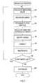
- the control device 8 calculates, from the captured image data, a measured value Ps1 (s1xn, s1yn, s1zn) of a three-dimensional shape of the object 1 at the first image-captured region (e.g., the region S1) (Step 100).
- the "s1x” denotes an X coordinate value
- the "s1y” denotes a Y coordinate value
- the "s1z” denotes a Z coordinate value.
- the index “n” denotes the "n” number of points to be measured.
- the "s1xn” denotes the “n” number of X coordinate values
- the “s1yn” denotes the “n” number of Y coordinate values
- the “s1zn” denotes the "n” number of Z coordinate values.
- the measured value of the three-dimensional shape includes the "n" number of (X coordinate value, Y coordinate value, Z coordinate value).
- the measured value is calculated based upon comparison of the imaged lattice pattern and the reference lattice pattern as described above. That is, the external shape of the object 1 is calculated backward with reference to a distortion degree of the imaged lattice pattern distorted in response to the external shape of the object 1.
- the X coordinate value, the Y coordinate value, the Z coordinate value are calculated with reference to the partial coordinate system for the region S1.
- control device 8 recognizes the marks 14 from the captured image data of the region S1 (Step 110).
- the control device 8 recognizes all the marks 14 that the control device 8 can recognize.
- the control device 8 calculates a center position of each of the marks 14 recognized.
- the control device 8 identifies the flat surface of the platen surface 12 from the captured image data of the region S1 (Step 115). Specifically, the control device 8 can identify the flat surface of the platen surface 12 from the arrangement of the marks 14 extracted. The control device 8 then compares the flat surface of the platen surface 12 identified from the captured image data with the platen surface 12 (i.e., the X-Y flat surface) on the reference coordinate system already stored in the control device 8 and calculates a deviation therebetween. Specifically, the control device 8 calculates an inclination of the platen surface 12 identified from the captured image data (in other words, a postural inclination of the CCD camera 4 relative to the platen surface 12).
- the control device 8 converts, based upon the deviation calculated, a value of the measured value Ps1 (s1xn, s1yn, s1zn) to a value with reference to the X-Y flat surface of the reference coordinate system stored in the control device 8.
- the purpose of the above is to match the X-axis direction and the Y-axis direction out of the X-axis, Y-axis, and Z-axis directions on the partial coordinate system to the X-axis direction and the Y-axis direction of the reference coordinate system.
- the Z-axis directions match each other naturally.
- the control device 8 calculates the sizes (diameters) of the marks 14 recognized and center distances P between the adjacent marks 14 (step 120).
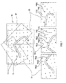
- the control device 8 extracts marks 14-1, 14-2, and 14-3 (see FIG. 4 ), which appears triangle shaped, from among the marks 14 recognized at Step 110. The control device 8 then calculates the sizes (diameters) of the marks 14-1, 14-2, and 14-3 and center distances P between adjacent marks 14 (Step 120).
- the control device 8 can extract three marks 14 in which the object 1 is interposed. For example, in FIG. 4 , the control device 8 can extract marks 14-1, 14-4 and 14-5 instead of the marks 14-1, 14-2 and 14-3.
- the three marks 14 can be identified.
- the X-axis direction or the Y-axis direction of the reference coordinate system stored in the control device 8 can not be identified based upon the measured value Ps1 (s1xn, s1yn, s1zn).
- the control device 8 calculates the sizes (diameters) of the three marks 14-1, 14-2, and 14-3 and the center distances P between individual adjacent marks.
- the control device 8 identifies to which marks 14 stored in the control device 8 (the marks 14 on the reference coordinate system) the three marks 14-1, 14-2, and 14-3 correspond respectively (Step 130).
- the three marks 14 can be identified based upon the sizes (diameters) of the marks 14 and values of respective internal or external angles of the triangle having the three marks 14 as its vertices.
- the control device 8 corrects the measured value Ps1 (s1xn, s1yn, s1zn) in such a manner that the three marks 14-1, 14-2, and 14-3 identified each overlap three corresponding marks 14 on the reference coordinate system already stored in the control device 8 (Step 140).
- This measured value corrected (hereinafter, referred to as a corrected measured value) is a value based upon the reference coordinate system stored in the control device 8.
- the measured value based upon the captured image data and the partial coordinate system can be converted to a value based upon the reference coordinate system with reference to the data on the marks 14 contained in the captured image data and the data on the marks 14 on the reference coordinate system already stored in the control device 8.
- the measured value Ps1 (s1xn, s1yn, s1zn) contains measured values denoting the platen surface 12 and the marks 14, the measured values denoting the platen surface 12 and the marks 14 are deleted (Step 145).
- Step 100 to Step 145 are repeatedly performed for the non-measured region in the same manner.
- Step 100 to Step 145 are completed for all regions (Step 150:No)
- the process moves to Step 200. More specifically, according to the embodiment, when all processes of Step 100 to Step 145 are completed for all the regions S1 to S5, the corrected measured values obtained for all the regions S1 to S5 are synthesized (Step 200).
- the corrected measured values are the values based upon the reference coordinate system. That is, the coordinate system for each corrected measured value for each region S1 to S5 is the same. Therefore, the corrected measured values for the regions S1 to S5 can be easily synthesized.
- the three-dimensional shape of the object 1 is measured by dividing the object 1 to the five regions S1 to S5.
- the division number however is not limited to five. Further, for example, it is possible to image-capture the regions S1 and S4 and to measure a distance L (see FIG. 4 ) between a hole H1 in the region S1 (see FIG. 4 ) and a hole H4 in the region S4 (see FIG. 4 ), without measuring the regions S2 and S3.
- the measuring method of the three-dimensional shape of the embodiment it is possible to easily synthesize the measured values of the regions S1 to S5 by matching the coordinate systems of the measured values of the regions S1 to S5 by the marks 14 formed on the platen surface 12. Further, because there is no need to provide marks on the object 1 itself, it is possible to avoid a portion where a three-dimensional shape is not measured.
- the second embodiment differs from the first embodiment in that information on arrangement of the marks 14 (specifically, the sizes (diameters) of the marks 14, the central distances Px, Py between the marks 14, etc.) is not stored by the control device 8.
- the object 1 is assumed to be a bent-pipe molding.
- the image-capturing of the object 1 by the CCD camera 4 is dividedly implemented several times.
- the entire object 1 is image-captured by being divided into three regions S1 to S3.
- the regions S1, S2, and S3 are determined so that at least three marks 14 (three marks 14 appearing triangle shaped) are not hidden behind the object 1 every time of image-capturing.
- the regions S1, S2, and S3 are determined such that the at least three marks 14 are contained in an overlapped portion among the regions S1, S2, and S3.
- the regions S1 and S2 share an overlapped portion
- the regions S2 and S3 share an overlapped portion.
- the regions S1, S2, and S3 are determined such that common three marks 14 are contained in the regions S1 and S2 and common three marks 14 are contained in the regions S2 and S3.
- the region S1 has three marks 14(o), 14(p), and 14(q), and the region S2 has the same three marks 14(o), 14(p), and 14(q). Further, the region S2 has other three marks 14(s), 14(t), and 14(u), and the region S3 has the same three marks 14(s), 14(t), and 14(u).
- the control device 8 calculates a measured value Ps1 (s1xn, s1yn, s1zn) of the region S1 (Step 100).
- the measured value is described above in the first embodiment.
- the control device 8 recognizes marks 14 from the captured image data of the region S1 (Step 110). Here, the control device 8 recognizes all the marks 14 which the control device 8 can identify. The control device 8 also calculates the center position of each of the marks 14 recognized.
- the control device 8 identifies a flat surface of the platen surface 12 from the captured image data of the region S1 (Step 115). Specifically, the control device 8 can identify the flat surface of the platen surface 12 from the arrangement of the marks 14 extracted. The control device 8 calculates the sizes (diameters) of the marks 14 recognized and the center distances P between the adjacent marks 14 (Step 120).
- Step 150:Yes the control device 8 implements the processes from Step 100 to Step 120 for the region not image-captured.
- Step 150: No the control device 8 moves to the process of Step 200a.
- the measured value for the region S1 is Ps1
- the measured value for the region S2 is Ps2
- the measured value for the region S3 is Ps3.
- Step 200a the control device 8 implements a process to synthesize the measured values Ps1, Ps2, and Ps3 for the regions S1, S2, and S3.
- the synthesizing process will be described below with reference to FIG. 6 .
- the control device 8 identifies the common marks 14 included in both of the regions S1 and S2 (Step 210).
- the platen surfaces 12 at the regions S1 and S2 identified at Step 115 are actually included in the same flat surface.
- the measured value Ps2 (s2xn, s2yn, s2zn) of the region S2 is corrected in such a manner that data (measured value) of the platen surface 12, which is contained in the captured image data of the region S1, and data (measured value) of the platen surface 12, which is contained in the captured image data of the region S2, indicate the same flat surface.
- correlation is implemented between the three marks 14 (i.e., the mark 14(o), the mark 14(p), and the mark 14(q)) recognized at the region S1 and the three marks (i.e., the mark 14(o), the mark 14(p), and the mark 14(q)) recognized at the region S2 (Step 210).
- the purpose of the correlation therebetween is to identify the mark 14(o), the mark 14(p), and the mark 14(q) (Step 210).
- the three marks 14 can be identified based upon the sizes (diameters) of the marks 14 and respective internal or external angles of the triangle having the three marks 14 as its vertexes.
- the measured value Ps2 (s2xn, s2yn, s2zn) of the region S2 is converted in such a manner that the three marks 14(o), 14(p), and 14(q) identified for the region S2 overlie the three marks 14(o), 14(p), and 14(q) identified for the region S1 (Step 220).
- coordinates (x11, y1, z11), (x12, y12, z12), and (x13, y13, z13) at the centers of the three marks 14(o), 14(p), and 14(q) in the region S1 are calculated from the measured value Ps1 of the region S1.
- Coordinates (x21, y21, z21), (x22, y22, z22), and (x23, y23, z23) at the centers of the three marks 14(o), 14(p), and 14(q) in the region S2 are calculated from the measured value Ps2 of the region S2.
- a partial coordinate system for the measured value Ps2 of the region S2 is converted to a partial coordinate system for the region S1 with reference to the coordinates (x11, y11, z11), (x12, y12, z12), and (x13, y13, z13) of the region S1 and the coordinates (x21, y21, z21), (x22, y22, z22), and (x23, y23, z23) of the region S2.
- the measured value Ps3 (s3xn, s3yn, s3zn) of the region S3 is corrected in such a manner that data (measured value) of the platen surface 12, which is contained in the captured image data of the region S2, and data (measured value) of the platen surface 12, which is contained in the captured image data of the region S3, indicate the same flat surface.
- correlation is implemented between the three marks 14 (i.e., the mark 14(s), the mark 14(t), and the mark 14(u)) recognized at the region S2 and the three marks (i.e” the mark 14(s), the mark 14(t), and the mark 14(u)) recognized at the region S3 (Step 230).
- the purpose of the correlation therebetween is to identify the marks 14 (i.e., the mark 14(o), the mark 14(p), and the mark 14(q)) (Step 230).
- the measured value Ps3 (s3xn, s3yn, s3zn) of the region S3 is converted in such a manner that the three marks 14(s), 14(t), and 14(u) identified for the region S3 overlie the three marks 14(s), 14(t), and 14(u) identified for the region S2.
- a partial coordinate for the measured value Ps3 of the region S3 is converted to the partial coordinate system for the region S2 (the measured value Ps3 is converted to a value based upon the partial coordinate system for the region S2).
- the measured value which is obtained by converting the measured value of the region S3 to the value based upon the partial coordinate system for the region S2, is converted to a value based upon the partial coordinate system of the region S1 (Step 240).
- Each measured value Ps contains measured values denoting the platen surface 12 and the marks 14, and the measured values denoting the platen surface 12 and the marks 14 are deleted (Step 250).
- the control process is then terminated. As a result, each of the measured values Ps1, Ps2, and Ps3 is converted to a value based upon the partial coordinate system of the region S1.
- each measured value can be converted to a value based upon the common coordinate system by use of the marks 14 provided on the platen surface 12, thus enabling to synthesize each measured value easily. Further, since the marks 14 are not provided at the object 1 itself, it is possible to avoid a portion where a three-dimensional shape is not measured.
- information on the reference coordinate system is stored in the control device 8 in advance.
- the information on the reference coordinate system can be obtained as follows, for example.
- the following description assumes that the measuring unit 3 is an automatic device which operates automatically.
- the control device 8 implements an initializing process when the measuring device 2 starts up. Specifically, first of all, the measuring unit 3 is returned to a predetermined origin position (initial position). Calibration of the measuring unit 3 is then implemented at the origin position. Specifically, at the origin position, the CCD camera 4 image-captures the platen surface 12 of the platen 10 so as to include the mark 14a.
- the reference coordinate system can be formed with the position of the mark 14a as the origin, the mark 14a being image-captured by the measuring unit 3 positioned at the origin position (initial position).
- the control device 8 stores in advance an estimated position of the mark 14a when the platen surface 12 is image-captured by the measuring unit 3 located at the origin position (initial position). The control device 8 then identifies, from information on the estimated position, the mark 14a from among the marks 14 contained in the captured image data. Further, only the mark 14a can be formed to have a unique shape so as to identify the mark 14a based upon the unique shape.
- the measuring unit 3 can be movable automatically in accordance with a predetermined program. Further, the measuring unit 3 can be mounted on a robot arm and be moved in response to an operation of the robot arm.
- a surface on which the object 1 is mounted is configured to be a platen surface (flat surface).
- the surface on which the object 1 is mounted can be configured to be a surface other than the flat surface.
Landscapes
- Engineering & Computer Science (AREA)
- Physics & Mathematics (AREA)
- General Physics & Mathematics (AREA)
- Computer Vision & Pattern Recognition (AREA)
- Theoretical Computer Science (AREA)
- Length Measuring Devices By Optical Means (AREA)
Applications Claiming Priority (2)
| Application Number | Priority Date | Filing Date | Title |
|---|---|---|---|
| JP2009198232A JP4856222B2 (ja) | 2009-08-28 | 2009-08-28 | 3次元形状測定方法 |
| PCT/JP2010/064483 WO2011024895A1 (ja) | 2009-08-28 | 2010-08-26 | 3次元形状測定方法及び3次元形状測定システム |
Publications (2)
| Publication Number | Publication Date |
|---|---|
| EP2472220A1 true EP2472220A1 (de) | 2012-07-04 |
| EP2472220A4 EP2472220A4 (de) | 2016-07-20 |
Family
ID=43627994
Family Applications (1)
| Application Number | Title | Priority Date | Filing Date |
|---|---|---|---|
| EP10811944.7A Withdrawn EP2472220A4 (de) | 2009-08-28 | 2010-08-26 | Verfahren zur messung dreidimensionaler formen und system zur messung dreidimensionaler formen |
Country Status (5)
| Country | Link |
|---|---|
| US (1) | US20120158358A1 (de) |
| EP (1) | EP2472220A4 (de) |
| JP (1) | JP4856222B2 (de) |
| KR (1) | KR20120090964A (de) |
| WO (1) | WO2011024895A1 (de) |
Families Citing this family (5)
| Publication number | Priority date | Publication date | Assignee | Title |
|---|---|---|---|---|
| CN103424084A (zh) * | 2012-06-25 | 2013-12-04 | 上海理工大学 | 基于二维激光位移传感器的砂轮三维形貌测量方法 |
| JP6710946B2 (ja) * | 2015-12-01 | 2020-06-17 | セイコーエプソン株式会社 | 制御装置、ロボットおよびロボットシステム |
| EP3252458A1 (de) * | 2016-06-01 | 2017-12-06 | Hijos de Jose Sivo, S.L. | System und verfahren zur digitalisierung dreidimensionaler objekte |
| CN110332886A (zh) * | 2019-06-21 | 2019-10-15 | 南京航空航天大学 | 一种视觉精密快速定位方法 |
| CN112164021A (zh) * | 2020-08-12 | 2021-01-01 | 中国科学院西安光学精密机械研究所 | 航天器载荷振动的图像测量方法及测量装置 |
Family Cites Families (16)
| Publication number | Priority date | Publication date | Assignee | Title |
|---|---|---|---|---|
| JPS61125712A (ja) * | 1984-11-26 | 1986-06-13 | Matsushita Electric Works Ltd | 多層印刷配線板の孔穿設法 |
| US5183373A (en) * | 1991-10-18 | 1993-02-02 | The Floyd And Gilbert Company | Circle marking and cutting guide template |
| EP0685709B1 (de) * | 1994-05-31 | 2001-12-05 | Japan Em Co., Ltd. | Apparat und Skala zum Messen einer Dimension eines Objektes |
| JPH1075391A (ja) * | 1996-08-30 | 1998-03-17 | Canon Inc | 被写体形状構成装置及び被写体形状構成方法 |
| DE19728513A1 (de) * | 1997-07-04 | 1999-01-07 | Daimler Benz Ag | Meßmarke und Verfahren zur Erkennung von Meßmarken sowie Verfahren zur Objektvermessung |
| JP2000238439A (ja) * | 1999-02-19 | 2000-09-05 | Dainippon Printing Co Ltd | 中間転写記録媒体及び画像形成方法 |
| JP4010753B2 (ja) * | 2000-08-08 | 2007-11-21 | 株式会社リコー | 形状計測システムと撮像装置と形状計測方法及び記録媒体 |
| WO2003012368A1 (en) * | 2001-07-30 | 2003-02-13 | Topcon Corporation | Surface shape measurement apparatus, surface shape measurement method, surface state graphic apparatus |
| JP4877891B2 (ja) * | 2001-08-03 | 2012-02-15 | 株式会社トプコン | 校正用被写体 |
| JP2003065736A (ja) * | 2001-08-24 | 2003-03-05 | Sanyo Electric Co Ltd | 3次元モデリング装置 |
| JP2004220510A (ja) | 2003-01-17 | 2004-08-05 | Minolta Co Ltd | 三次元形状測定装置、三次元形状測定方法及びターゲットマーク |
| JP3779308B2 (ja) * | 2004-07-21 | 2006-05-24 | 独立行政法人科学技術振興機構 | カメラ校正システム及び三次元計測システム |
| JP2006038590A (ja) * | 2004-07-26 | 2006-02-09 | Teruaki Yogo | 3次元形状測定方法及びその装置 |
| JP2006119005A (ja) * | 2004-10-22 | 2006-05-11 | Ryonichi Engineering Co Ltd | 大規模構造物計測装置及び大規模構造物計測方法 |
| JP4396564B2 (ja) * | 2005-04-01 | 2010-01-13 | 株式会社島津製作所 | 物体のモニタリング方法およびこれを用いたモーショントラッカ |
| JP4743771B2 (ja) * | 2006-05-08 | 2011-08-10 | コニカミノルタセンシング株式会社 | 断面データ取得方法、システム、及び断面検査方法 |
-
2009
- 2009-08-28 JP JP2009198232A patent/JP4856222B2/ja not_active Expired - Fee Related
-
2010
- 2010-08-26 US US13/392,475 patent/US20120158358A1/en not_active Abandoned
- 2010-08-26 WO PCT/JP2010/064483 patent/WO2011024895A1/ja not_active Ceased
- 2010-08-26 KR KR1020127005942A patent/KR20120090964A/ko not_active Ceased
- 2010-08-26 EP EP10811944.7A patent/EP2472220A4/de not_active Withdrawn
Non-Patent Citations (1)
| Title |
|---|
| See references of WO2011024895A1 * |
Also Published As
| Publication number | Publication date |
|---|---|
| EP2472220A4 (de) | 2016-07-20 |
| WO2011024895A1 (ja) | 2011-03-03 |
| JP2011047876A (ja) | 2011-03-10 |
| JP4856222B2 (ja) | 2012-01-18 |
| US20120158358A1 (en) | 2012-06-21 |
| KR20120090964A (ko) | 2012-08-17 |
Similar Documents
| Publication | Publication Date | Title |
|---|---|---|
| CN110555889B (zh) | 一种基于CALTag和点云信息的深度相机手眼标定方法 | |
| US8265376B2 (en) | Method and system for providing a digital model of an object | |
| US8345954B2 (en) | Method and apparatus for the three-dimensional digitization of objects | |
| KR101879224B1 (ko) | 차량 휠 얼라인먼트를 결정하는 시스템 및 관련 방법 | |
| CN107218904B (zh) | 一种基于锯齿靶标的线结构光视觉传感器标定方法 | |
| EP2195608B1 (de) | System und verfahren zur mehrbild-oberflächenmessung der form von objekten | |
| EP3783385A1 (de) | Kombinierte punktwolkenerzeugung unter verwendung eines stationären laserscanners und eines mobilen scanners | |
| JP6282098B2 (ja) | キャリブレーション装置及び方法 | |
| US20140029018A1 (en) | Calibration of laser light section sensors during simultaneous measurement | |
| JP5222430B1 (ja) | 寸法計測装置、寸法計測方法及び寸法計測装置用のプログラム | |
| EP2472220A1 (de) | Verfahren zur messung dreidimensionaler formen und system zur messung dreidimensionaler formen | |
| CN101109620A (zh) | 一种结构光视觉传感器结构参数标定方法 | |
| KR102093674B1 (ko) | 변형 가공 지원 시스템 및 변형 가공 지원 방법 | |
| CN106548489A (zh) | 一种深度图像与彩色图像的配准方法、三维图像采集装置 | |
| US20190392607A1 (en) | Image processing apparatus, system, image processing method, article manufacturing method, and non-transitory computer-readable storage medium | |
| JP2018066579A (ja) | 車載カメラのキャリブレーション装置及び車載カメラのキャリブレーション方法 | |
| JPH11160021A (ja) | 広域3次元位置計測方法及び装置 | |
| KR100886655B1 (ko) | 로봇 기반 멀티 레이저 비전 시스템의 자동 캘리브레이션방법 | |
| US20250231021A1 (en) | Surface shape measurement device | |
| JP6186431B2 (ja) | キャリブレーション装置、キャリブレーションシステム、及び撮像装置 | |
| JP6043974B2 (ja) | 三次元位置測定装置、三次元測定装置及び三次元位置測定プログラム | |
| JP2005221243A (ja) | 3次元形状計測装置および方法 | |
| JP2013134176A (ja) | 撮像装置および撮像方法 | |
| CN117325455A (zh) | 一种基于单目视觉的3d打印对齐方法 | |
| JP7620441B2 (ja) | ワーク検出装置、ワーク検出方法、ワーク検出システム及びワーク検出プログラム |
Legal Events
| Date | Code | Title | Description |
|---|---|---|---|
| PUAI | Public reference made under article 153(3) epc to a published international application that has entered the european phase |
Free format text: ORIGINAL CODE: 0009012 |
|
| 17P | Request for examination filed |
Effective date: 20120328 |
|
| AK | Designated contracting states |
Kind code of ref document: A1 Designated state(s): AL AT BE BG CH CY CZ DE DK EE ES FI FR GB GR HR HU IE IS IT LI LT LU LV MC MK MT NL NO PL PT RO SE SI SK SM TR |
|
| DAX | Request for extension of the european patent (deleted) | ||
| RA4 | Supplementary search report drawn up and despatched (corrected) |
Effective date: 20160621 |
|
| RIC1 | Information provided on ipc code assigned before grant |
Ipc: G06T 7/00 20060101ALI20160615BHEP Ipc: G01B 11/25 20060101ALI20160615BHEP Ipc: G06T 7/60 20060101ALI20160615BHEP Ipc: G01B 11/24 20060101AFI20160615BHEP |
|
| STAA | Information on the status of an ep patent application or granted ep patent |
Free format text: STATUS: THE APPLICATION HAS BEEN WITHDRAWN |
|
| 18W | Application withdrawn |
Effective date: 20180913 |