EP2472271A1 - Oszilloskop und verfahren, syste dafür zum sammeln und anzeigen einer signalwellenform - Google Patents
Oszilloskop und verfahren, syste dafür zum sammeln und anzeigen einer signalwellenform Download PDFInfo
- Publication number
- EP2472271A1 EP2472271A1 EP10845565A EP10845565A EP2472271A1 EP 2472271 A1 EP2472271 A1 EP 2472271A1 EP 10845565 A EP10845565 A EP 10845565A EP 10845565 A EP10845565 A EP 10845565A EP 2472271 A1 EP2472271 A1 EP 2472271A1
- Authority
- EP
- European Patent Office
- Prior art keywords
- test
- unit
- waveform data
- collecting
- tested object
- Prior art date
- Legal status (The legal status is an assumption and is not a legal conclusion. Google has not performed a legal analysis and makes no representation as to the accuracy of the status listed.)
- Withdrawn
Links
Images


Classifications
-
- G—PHYSICS
- G01—MEASURING; TESTING
- G01R—MEASURING ELECTRIC VARIABLES; MEASURING MAGNETIC VARIABLES
- G01R13/00—Arrangements for displaying electric variables or waveforms
- G01R13/02—Arrangements for displaying electric variables or waveforms for displaying measured electric variables in digital form
-
- G—PHYSICS
- G01—MEASURING; TESTING
- G01R—MEASURING ELECTRIC VARIABLES; MEASURING MAGNETIC VARIABLES
- G01R31/00—Arrangements for testing electric properties; Arrangements for locating electric faults; Arrangements for electrical testing characterised by what is being tested not provided for elsewhere
- G01R31/28—Testing of electronic circuits, e.g. by signal tracer
- G01R31/2832—Specific tests of electronic circuits not provided for elsewhere
- G01R31/2836—Fault-finding or characterising
Definitions
- the present invention relates to the field of collection and test of signals of electronic products, and particularly, to an oscilloscope and a method, a system for collecting and displaying signal waveform.
- oscilloscopes either the mid-end, high-end or low-end oscilloscopes, adopted in hardware testing field of electronic products all adopt a traditional manual way of hand-held probe to collect tested signals.
- PCB Print Circuit Board
- test report The work of arranging the test report is also very heavy due to numerous test data, and that is because the report always can not correspond to a PCB diagram, thus people have to look up the PCB diagram and elementary diagram when reading the test report, thereby also making the readability of the report worse.
- the technical problem to be solved by the present invention is to provide an oscilloscope and a method, a system thereof for collecting and displaying signal waveform, which can automatically control the positioning of a point to be tested of a tested object and the collection and display of the signal waveform.
- the present invention provides a method for collecting and displaying signal waveform, which relates to a control measuring unit and an automatic collecting unit, and the method comprises:
- the control measuring unit determining the corresponding test command and test parameter according to the selection of test points on the tested object comprises: the control measuring unit selecting a corresponding type of collecting probe according to variety, frequency and amplitude of signals of each test point of the tested object, and setting test parameters of vertical and/or horizontal and triggering of each data channel; the step of the control measuring unit calculating the position coordinates of each test point comprises: calculating out the position coordinates of each test point according to detected original position coordinates of the tested object; the step of the control measuring unit sending the test command and test parameter to the automatic collecting unit comprises: sending the test command and test parameter at least including the position coordinates of the test point and the test command and test parameter of a selected probe to the automatic collecting unit; the step of the automatic collecting unit returning the test signals of each test point collected by the collecting probe to the control measuring unit according to the test command and test parameter comprises: the automatic collecting unit sending the selected probe to a specified position according to the position coordinates of the test point in the test command, carrying the probe to a specified position coordinate to contact with a
- the step of the control measuring unit calculating the position coordinates of each test point further comprises: the control measuring unit detecting the original position coordinates of the tested object through optical positioning; the multi-coordinate motion trajectory formed by the automatic collecting unit comprises any one of the spatial rectangular three-coordinate motion trajectory or polar coordinate motion trajectory, or the plane rectangular coordinate motion trajectory or polar coordinate motion trajectory; the step of the control measuring unit displaying the waveform data comprises: controlling displaying the waveform data of the corresponding channel according to a human-computer interaction command, and/or implementing an associated display with a design document of the tested object according to the waveform data.
- the present invention provides an oscilloscope, which comprises a control measuring unit and an automatic collecting unit, wherein:
- the control measuring unit comprises: a comprehensive controlling unit and a signal measuring and waveform data generating unit
- the automatic collecting unit comprises: a collecting probe servo unit and one or more collecting probes, wherein:
- the control measuring unit further comprises a tested object positioning unit, wherein:
- the comprehensive controlling unit is further configured to: select a corresponding type of collecting probe according to one or more attributes of the variety, frequency and amplitude of the signals of each test point of the tested object; the collecting probe servo unit is configured to carry the supported and borne collecting probe to the specified position coordinates to contact with the corresponding test point according to a following way: carrying the collecting probe selected by the comprehensive controlling unit to be under the position coordinates through a formed multi-coordinate motion trajectory under control of the comprehensive controlling unit, and guaranteeing a good contact; the multi-coordinate motion trajectory comprising any one of spatial rectangular three-coordinate motion trajectory or polar coordinate motion trajectory, or plane rectangular coordinate motion trajectory or polar coordinate motion trajectory.
- the comprehensive controlling unit is further configured to: set test parameters of verticalness and/or horizon and triggering of each channel of the signal measuring and waveform data generating unit according to one or more attributes of variety, frequency and amplitude of signals of each test point of the tested object; receive and store waveform data transferred by the signal measuring and waveform data generating unit; the signal measuring and waveform data generating unit is further configured to: transfer the generated waveform data of each channel to the comprehensive controlling unit.
- the control measuring unit further comprises a human-computer interaction unit, wherein:
- the present invention provides a system for collecting and displaying signal waveform, wherein, the system comprises: a calculating and controlling device, a signal measuring and waveform data generating device, a collecting probe servo device and one or more collecting probes, wherein:
- a tested object positioning device is further comprised, wherein:
- the calculating and controlling device is further configured to: select a corresponding type of collecting probe according to one or more attributes of the variety, frequency and amplitude of the signals of each test point of the tested object; the collecting probe servo device is configured to carry the supported and borne collecting probe to the specified position coordinates to contact with the corresponding test point according to a following way: carrying the collecting probe selected by the calculating and controlling device to be under the position coordinates through a formed multi-coordinate motion trajectory under control of the comprehensive controlling unit, and guaranteeing a good contact by exerting an appropriate force on the collecting probe; the multi-coordinate motion trajectory comprising any one of a spatial rectangular three-coordinate motion trajectory or polar coordinate motion trajectory, or a plane rectangular coordinate motion trajectory or polar coordinate motion trajectory.
- the calculating and controlling device is further configured to: set test parameters of verticalness and/or horizon and triggering of each channel of the signal measuring and waveform data generating unit according to one or more attributes of variety, frequency and amplitude of the signals of each test point of the tested object; receive and store the waveform data transferred by the signal measuring and waveform data generating device; the signal measuring and waveform data generating device is further configured to: transfer the generated waveform data of each channel to the calculating and controlling device.
- the calculating and controlling device comprises a human-computer interaction device, wherein:
- the system further comprises a tested object fixing device, which is configured to: fix or unfix the tested object under the control of the calculating and controlling device.
- the present invention overcomes the problems and defects existing in the above traditional oscilloscope, and provides an oscilloscope and a corresponding system and method, which accurately positions and contacts the test point of the tested object by automatically controlling one or multiple collecting probes, so as to collect, store and display the signal waveform of the test point automatically. Meanwhile, the test results can also be directly displayed on the corresponding PCB diagram.
- the present invention is especially applicable to the comprehensive test and batch consistency test of the high-density and complicated PCB, and can save a large amount of test labor, which greatly improves the efficiency, accuracy and reliability of the test and shortens the development cycle of the hardware.
- FIG. 1 it is a structure of the example of oscilloscope device, which can automatically position, collect and display the signal waveform of a test point, provided by the present invention, and the oscilloscope device comprises a control measuring unit and an automatic collecting unit, wherein:
- control measuring unit further comprises: a comprehensive controlling unit, a tested object positioning unit and a signal measuring and waveform data generating unit
- automatic collecting unit further comprises: a collecting probe servo unit and one or more collecting probes, wherein:
- the comprehensive controlling unit also receives and stores test data from the signal measuring and waveform data generating unit, and records the test data on a PCB diagram of a corresponding tested object (such as a circuit board, bare machine or semi-finished product of the electronic products and so on).
- a PCB diagram of a corresponding tested object such as a circuit board, bare machine or semi-finished product of the electronic products and so on.
- the tested object positioning unit is used to: collect the original position coordinate of the tested object according to the test command and test parameter thereof, and transfer the original position coordinate of the tested object to the comprehensive controlling unit; the tested object positioning unit collects the original position coordinate of the tested object, for example, in the way of optical scanning.
- the signal measuring and waveform data generating unit is used to: complete a test configuration according to the test command and test parameter thereof, receive the test signals of the test point detected by one or more collecting probes and transferred by the collecting probe servo unit via one or more channels, generate the waveform data accordingly, and transfer the generated test data of each channel to the comprehensive controlling unit at the same time;
- the collecting probe servo unit is used to: support and bear one or more collecting probes, form a multi-coordinate motion trajectory under the control of the comprehensive controlling unit, carry the collecting probe to the specified position coordinate to contact with the test point, and transfer the test signals of the test point collected by the collecting probe to the signal measuring and waveform data generating unit;
- the collecting probe servo unit also exerts an appropriate force on the collecting probe to guarantee a good contact between the probe and test point.
- the multi-coordinate motion trajectory formed by the collecting probe servo unit is a spatial rectangular three-coordinate (x, y, z) motion trajectory or polar coordinate (r, ⁇ , ⁇ ) motion trajectory; or is a plane rectangular coordinate (x, y) motion trajectory or polar coordinate (r, ⁇ ) motion trajectory.
- One or more collecting probes are used to: implement an accurate positioning and contact with the test point of the tested object (i.e. the PCB) under the control of the multi-coordinate motion trajectory of the collecting probe servo unit, and output the test signals collected from the test point to the collecting probe servo unit.
- the test point of the tested object i.e. the PCB
- the above oscilloscope device further comprises a human-computer interaction unit, which is used to: provide the variety of the collecting probe and the information of the tested object and test point thereof under the control of the comprehensive controlling unit, and transfer a human-computer interaction command to the comprehensive controlling unit; the comprehensive controlling unit controls the human-computer interaction unit to display the waveform of the corresponding channel according to the human-computer interaction command.
- a human-computer interaction unit which is used to: provide the variety of the collecting probe and the information of the tested object and test point thereof under the control of the comprehensive controlling unit, and transfer a human-computer interaction command to the comprehensive controlling unit; the comprehensive controlling unit controls the human-computer interaction unit to display the waveform of the corresponding channel according to the human-computer interaction command.
- One or more collecting probes of the present invention can adapt to the requirements of the signals of various test points with different frequencies, amplitudes and earthing conditions. After arriving at the specified coordinates and implementing a contact with the signal of the test point, each collecting probe can perform the test in sequence, and also can perform the test in parallel, to improve the test efficiency.
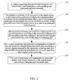
- FIG. 2 it is a flow of the example of method of using the oscilloscope provided by the present invention to collect and display signal waveform, and the following steps are comprised.
- a control measuring unit selects each test point on a tested object, and determines a corresponding test command and test parameter.
- the control measuring unit firstly fixes the respective positions of the tested object and collecting probe servo device relatively.
- the tested object for example is a print circuit board (PCB), bare machine or semi-finished product of the electronic products and so on.
- PCB print circuit board
- step 120 the position coordinate of the test point on the tested object is calculated and acquired according to the determined initial position coordinate of the tested object, and a test command including other test parameters such as the position coordinate of the test point and a selected probe and so on is sent to the automatic collecting unit.
- the control measuring unit detects the initial position coordinate of the tested object, and selects the test point on the tested object; acquires a signal parameter of the test point, and thus sets the waveform to display test parameters of verticalness or horizon and triggering and so on of each channel, and selects a corresponding type of probe.
- the detection of the initial position coordinate of the tested object comprises detecting the initial position coordinates of the tested object through the optical positioning of a tested object positioning device.
- the signal parameter of the test point includes one or multiple kinds of the parameters of signal variety, frequency and amplitude, and is acquired through the design document (e.g., the PCB diagram) of the tested object or through a human-computer interface.
- step 130 the automatic collecting unit sends the selected probe to a specified position according to the position coordinate of the test point in the test command, and returns test signals collected by the probe to the control measuring unit.
- the automatic collecting unit forms a multi-coordinate motion trajectory under the control of the control measuring unit to send the selected probe to the specified position, which for example is the spatial rectangular three-coordinate (x, y, z) motion trajectory or polar coordinate (r, ⁇ , ⁇ ) motion trajectory; or is the plane rectangular coordinate (x, y) motion trajectory or polar coordinate (r, ⁇ ) motion trajectory.
- the automatic collecting unit makes the probe and test point in a good electrical contact.
- step 140 the control measuring unit generates corresponding waveform data according to the test signals returned by the automatic collecting unit and stores the corresponding waveform data, which are displayed on corresponding data channels at the same time.
- step 150 the control measuring unit implements an associated display with design document of the tested object according to the generated waveform data.
- the control measuring unit for example records the index of the received waveform data on the PCB diagram of the corresponding tested object.
- next test point can be selected, and the above steps 120 ⁇ 150 are repeated.
- the above method further comprises a step: a human-computer interaction unit of the control measuring unit provides the variety of the collecting probe and the information of the tested object and test point thereof, and transfers a human-computer interaction command to the control measuring unit; the control measuring unit controls the human-computer interaction unit to display waveform of the corresponding channel according to the human-computer interaction command.
- FIG. 3 it is a structure of the example of system, which can automatically position, collect and display signal waveform of a test point, provided by the present invention, and the system comprises: a calculating and controlling device, a signal measuring and waveform data generating device, a tested object positioning device, a collecting probe servo device and one or more collecting probes, wherein:
- the calculating and controlling device also receives and stores test data from the signal measuring and waveform data generating device through a test result storing and recording device, and records the test data on the PCB diagram of the corresponding tested object (such as a circuit board, bare machine or semi-finished product of the electronic products and so on).
- the tested object positioning device is used to: transfer the collected original position coordinate of the tested object to the calculating and controlling device according to the test command and test parameter thereof; the tested object positioning device for example collects the original position coordinate of the tested object in the way of optical scanning.
- the signal measuring and waveform data generating device is used to: complete a test configuration according to the test command and test parameter thereof, receive and display the test signals of the test point detected by one or more collecting probes and transferred by the collecting probe servo device through one or more channels, generate the waveform data, and transfer the generated test data of each channel to the calculating and controlling device at the same time.
- the collecting probe servo device is used to: support and bear one or more collecting probes, form a multi-coordinate motion trajectory according to the test command and test parameter thereof, carry the collecting probe to a specified position coordinate to contact with a test point, and transfer the test signals of the test point collected by the collecting probe to the signal measuring and waveform data generating device; the collecting probe servo device also exerts an appropriate force on the collecting probe to guarantee a good contact between the probe and the test point.
- the collecting probe servo unit forms a multi-coordinate motion trajectory through a servo controlling unit, and the multi-coordinate motion trajectory for example is a spatial rectangular three-coordinate (x, y, z) motion trajectory or polar coordinate (r, ⁇ , ⁇ ) motion trajectory, or is a plane rectangular coordinate (x, y) motion trajectory or polar coordinate (r, ⁇ ) motion trajectory.
- One or more collecting probes are used to: implement an accurate positioning and contact with the test point of the tested object under the control of the multi-coordinate motion trajectory of the collecting probe servo device, and output the test signals collected from the test point to the collecting probe servo device.
- the above system provides the variety of the collecting probe and the information of the tested object and test point thereof through a human-computer interaction device (not shown in the figure, such as a keyboard and an output display screen and so on) in the calculating and controlling device, and transfer a human-computer interaction command at the same time; the calculating and controlling device controls the human-computer interaction device to display the waveform of the corresponding channel according to the human-computer interaction command.
- a human-computer interaction device not shown in the figure, such as a keyboard and an output display screen and so on
- the calculating and controlling device controls the human-computer interaction device to display the waveform of the corresponding channel according to the human-computer interaction command.
- the system shown in FIG. 3 further comprises a tested object fixing device, which is used to fix or unfix the tested object under the control of the calculating and controlling device, such as the tested object is clamped or unclamped through a forcipated cramp, or is locked or unlocked through a push lock, etc..
- a tested object fixing device which is used to fix or unfix the tested object under the control of the calculating and controlling device, such as the tested object is clamped or unclamped through a forcipated cramp, or is locked or unlocked through a push lock, etc.
- the calculating and controlling device can pre-select each test point in batch on the design documents such as the PCB diagram of the tested object and so on, controls by a program the collecting probe servo device to automatically and accurately position the collecting probe to the test point, inputs and stores the waveform data generated by the signal measuring and waveform data generating device, and directly records the test results on the PCB diagram.
- the present invention replaces the method for implementing the collection and display of signal waveform through the manually hand-held probe in the traditional oscilloscope, and makes signal waveform of the tested signals, in a way of a batch pre-selection on the design documents such as PCB diagram, be automatically input and stored into the oscilloscope through a multi-coordinate collecting probe controlled by the program, and directly record the test results on the PCB diagram. Therefore, the present invention is especially applicable to the comprehensive test and batch consistency test of the high-density and complicated PCB of the high-end product and may save a large amount of test labor, which greatly improves the efficiency, accuracy and reliability of the test, thereby effectively shortening the development cycle of the hardware.
- the present invention overcomes the problems and defects existing in the above traditional oscilloscope, and provides an oscilloscope and a corresponding system and method, which accurately collects, stores and displays signal waveform of the test point by automatically controlling one or multiple collecting probes to accurately position and contact with the test point of the tested object. Meanwhile, the test results can also be directly displayed on the corresponding PCB diagram.
- the present invention is especially applicable to the comprehensive test and batch consistency test of a high-density and complicated PCB and can save a large amount of test labor, which greatly improves the efficiency, accuracy and reliability of the test and shortens the development cycle of the hardware.
Landscapes
- Physics & Mathematics (AREA)
- General Physics & Mathematics (AREA)
- Tests Of Electronic Circuits (AREA)
Applications Claiming Priority (2)
| Application Number | Priority Date | Filing Date | Title |
|---|---|---|---|
| CN2010101257236A CN101788579B (zh) | 2010-02-09 | 2010-02-09 | 一种示波器及其信号波形采集及显示的方法及系统 |
| PCT/CN2010/077923 WO2011097895A1 (zh) | 2010-02-09 | 2010-10-20 | 一种示波器及其信号波形采集及显示的方法及系统 |
Publications (2)
| Publication Number | Publication Date |
|---|---|
| EP2472271A1 true EP2472271A1 (de) | 2012-07-04 |
| EP2472271A4 EP2472271A4 (de) | 2017-11-01 |
Family
ID=42531867
Family Applications (1)
| Application Number | Title | Priority Date | Filing Date |
|---|---|---|---|
| EP10845565.0A Withdrawn EP2472271A4 (de) | 2010-02-09 | 2010-10-20 | Oszilloskop und verfahren, syste dafür zum sammeln und anzeigen einer signalwellenform |
Country Status (5)
| Country | Link |
|---|---|
| US (1) | US9128126B2 (de) |
| EP (1) | EP2472271A4 (de) |
| JP (1) | JP5395272B2 (de) |
| CN (1) | CN101788579B (de) |
| WO (1) | WO2011097895A1 (de) |
Cited By (1)
| Publication number | Priority date | Publication date | Assignee | Title |
|---|---|---|---|---|
| CN102565478A (zh) * | 2010-12-30 | 2012-07-11 | 鸿富锦精密工业(深圳)有限公司 | 示波器数据处理系统及方法 |
Families Citing this family (23)
| Publication number | Priority date | Publication date | Assignee | Title |
|---|---|---|---|---|
| CN101788579B (zh) * | 2010-02-09 | 2013-06-05 | 中兴通讯股份有限公司 | 一种示波器及其信号波形采集及显示的方法及系统 |
| CN102175902B (zh) * | 2011-01-04 | 2013-11-06 | 苏州瀚瑞微电子有限公司 | 示波器处理数字波形的系统及方法 |
| JP5200198B1 (ja) * | 2011-10-03 | 2013-05-15 | パナソニック株式会社 | 動作確認支援装置および動作確認支援方法 |
| CN103176008B (zh) * | 2011-12-22 | 2017-08-25 | 北京普源精电科技有限公司 | 一种具有可控测量功能的示波器及其实现方法 |
| CN104049118B (zh) * | 2013-03-14 | 2017-03-01 | 固纬电子实业股份有限公司 | 以趋势图显示波形测量参数的示波器 |
| CN104251966A (zh) * | 2013-06-25 | 2014-12-31 | 鸿富锦精密工业(深圳)有限公司 | 自动化测量系统及方法 |
| CN104345260A (zh) * | 2013-08-01 | 2015-02-11 | 鸿富锦精密工业(深圳)有限公司 | 信号完整性自动化测试系统及方法 |
| CN104680963A (zh) * | 2015-03-26 | 2015-06-03 | 京东方科技集团股份有限公司 | 一种显示面板goa电路的检测装置和检测方法 |
| CN107038395B (zh) * | 2017-04-13 | 2023-04-28 | 杨军 | 一种地铁专用读卡器综合测试台及测试方法 |
| CN108303577B (zh) * | 2018-01-03 | 2020-07-24 | 威创集团股份有限公司 | 示波器测试方法、装置以及示波器 |
| CN109195172A (zh) * | 2018-07-27 | 2019-01-11 | 闻泰通讯股份有限公司 | 射频测试方法、装置、测试设备及存储介质 |
| CN109581017B (zh) * | 2018-11-28 | 2021-06-29 | 北京宏动科技有限公司 | 多功能数字式瞬态响应测试仪 |
| CN110850269A (zh) * | 2019-10-11 | 2020-02-28 | 深圳市元征科技股份有限公司 | 测试系统、测试方法、控制设备和存储介质 |
| CN110850136A (zh) * | 2019-11-12 | 2020-02-28 | 深圳宝龙达信创科技股份有限公司 | 示波器的测试方法、终端设备及计算机可读存储介质 |
| CN111476986B (zh) * | 2020-03-10 | 2021-05-25 | 上海卫星工程研究所 | 遥控指令脉冲波形测试方法 |
| CN113777464B (zh) * | 2020-06-10 | 2024-09-13 | 深南电路股份有限公司 | 一种电路板功能测试装置、系统及方法 |
| CN116794415A (zh) * | 2022-03-18 | 2023-09-22 | 长鑫存储技术有限公司 | 探针针况的监控方法、测试系统、计算机设备和存储介质 |
| CN114660438A (zh) * | 2022-03-23 | 2022-06-24 | 艾富瑞(苏州)测试科技有限公司 | 一种飞针设备上探针的弹力测试系统及其方法 |
| CN114740401B (zh) * | 2022-03-24 | 2022-11-18 | 深圳市三一联光智能设备股份有限公司 | 一种产品元件的测试方法及系统 |
| CN118191443A (zh) * | 2022-11-24 | 2024-06-14 | 吴伟 | 一种电磁干扰测试方法和系统 |
| CN116522878B (zh) * | 2023-07-04 | 2023-10-24 | 成都领目科技有限公司 | 示波器测试数据保持一致性导入报告的方法、装置及介质 |
| WO2025118298A1 (en) * | 2023-12-08 | 2025-06-12 | Abb Schweiz Ag | Method and system for electrical test |
| CN119147813B (zh) * | 2024-10-11 | 2025-03-11 | 成都玖锦科技有限公司 | 模板测试数据生成方法、装置、设备及存储介质 |
Family Cites Families (15)
| Publication number | Priority date | Publication date | Assignee | Title |
|---|---|---|---|---|
| JPH01212369A (ja) * | 1988-02-19 | 1989-08-25 | Nec Home Electron Ltd | 信号波形検査方法 |
| JPH07113658B2 (ja) * | 1990-11-19 | 1995-12-06 | グラフテック株式会社 | 回路試験装置 |
| CN1074539A (zh) * | 1992-12-29 | 1993-07-21 | 马越 | 多通道数字式示波卡 |
| JPH0850163A (ja) * | 1994-08-05 | 1996-02-20 | Mitsubishi Electric Corp | プロービング装置 |
| US5550483A (en) * | 1994-11-18 | 1996-08-27 | International Business Machines | High speed test probe positioning system |
| US5994909A (en) * | 1997-08-25 | 1999-11-30 | Lucas; Brian K. | Robotic twin probe for measurement on printed circuit boards and electrical and electronic assemblies |
| US6975956B2 (en) * | 2002-09-19 | 2005-12-13 | Rambus Inc. | Multiple sweep point testing of circuit devices |
| US20060047449A1 (en) * | 2004-08-27 | 2006-03-02 | Broadcom Corporation | Graphical test development tool for use with automated test equipment |
| CN100353410C (zh) * | 2004-11-25 | 2007-12-05 | 上海交通大学 | Co2短路过渡过程参数波形的动态显示系统 |
| JP2007121183A (ja) * | 2005-10-31 | 2007-05-17 | Hioki Ee Corp | 回路基板検査装置 |
| JP2007199019A (ja) * | 2006-01-30 | 2007-08-09 | Hioki Ee Corp | 表示制御装置 |
| US7681091B2 (en) * | 2006-07-14 | 2010-03-16 | Dft Microsystems, Inc. | Signal integrity measurement systems and methods using a predominantly digital time-base generator |
| CN101350005A (zh) * | 2007-07-17 | 2009-01-21 | 鸿富锦精密工业(深圳)有限公司 | 信号转态区间非单调性的分析系统及方法 |
| CN101413968B (zh) | 2008-09-30 | 2010-09-01 | 中国电子科技集团公司第四十一研究所 | 一种数字示波器及其操纵显示波形的方法 |
| CN101788579B (zh) * | 2010-02-09 | 2013-06-05 | 中兴通讯股份有限公司 | 一种示波器及其信号波形采集及显示的方法及系统 |
-
2010
- 2010-02-09 CN CN2010101257236A patent/CN101788579B/zh not_active Expired - Fee Related
- 2010-10-20 WO PCT/CN2010/077923 patent/WO2011097895A1/zh not_active Ceased
- 2010-10-20 US US13/499,938 patent/US9128126B2/en not_active Expired - Fee Related
- 2010-10-20 EP EP10845565.0A patent/EP2472271A4/de not_active Withdrawn
- 2010-10-20 JP JP2012532448A patent/JP5395272B2/ja not_active Expired - Fee Related
Non-Patent Citations (1)
| Title |
|---|
| See references of WO2011097895A1 * |
Cited By (1)
| Publication number | Priority date | Publication date | Assignee | Title |
|---|---|---|---|---|
| CN102565478A (zh) * | 2010-12-30 | 2012-07-11 | 鸿富锦精密工业(深圳)有限公司 | 示波器数据处理系统及方法 |
Also Published As
| Publication number | Publication date |
|---|---|
| JP5395272B2 (ja) | 2014-01-22 |
| WO2011097895A1 (zh) | 2011-08-18 |
| US20120203500A1 (en) | 2012-08-09 |
| CN101788579A (zh) | 2010-07-28 |
| US9128126B2 (en) | 2015-09-08 |
| EP2472271A4 (de) | 2017-11-01 |
| JP2013506853A (ja) | 2013-02-28 |
| CN101788579B (zh) | 2013-06-05 |
Similar Documents
| Publication | Publication Date | Title |
|---|---|---|
| US9128126B2 (en) | Oscilloscope and method, system thereof for collecting and displaying signal waveform | |
| CN101865975B (zh) | 主板测试系统及方法 | |
| CN101221210B (zh) | 一种成品线路板自动测试校正系统及其自动测试校正方法 | |
| US8081008B2 (en) | System and method for testing a characteristic impedance of an electronic component | |
| US20140375346A1 (en) | Test control device and method for testing signal integrities of electronic product | |
| CN102636698A (zh) | 电路板自动化测试系统及方法 | |
| CN101650377A (zh) | 信号测量系统及方法 | |
| CN103995202A (zh) | 一种自动信号测试方法、装置及系统 | |
| CN112067971A (zh) | 基于vi曲线故障现象矩阵对比快速隐患检测与诊断方法 | |
| CN104251966A (zh) | 自动化测量系统及方法 | |
| CN115408228B (zh) | 一种触摸屏设备自动化测试方法、装置及系统 | |
| US6845480B2 (en) | Test pattern generator and test pattern generation | |
| JP2011203001A (ja) | プローブカード検査装置、検査方法及び検査システム | |
| CN86102660A (zh) | 印刷电路板功能测试系统以及使用上述系统的方法 | |
| CN113253096A (zh) | 一种印刷电路自动检测系统及检测方法 | |
| CN119511041A (zh) | 一种基于飞针测试仪的电路板测试方法与装置 | |
| CN220020273U (zh) | 一种硬件板卡自动化白盒测试装置 | |
| CN212622761U (zh) | 自动标记示波器及自动标记系统 | |
| WO2005121814A1 (en) | Logic analyzer and method of analyzing waveform data using the same | |
| JP2001350646A (ja) | 半導体試験システム | |
| TWI412754B (zh) | 特性阻抗測試系統及方法 | |
| CN221280313U (zh) | 一种数字面板表程控校准辅助装置 | |
| CN115963302A (zh) | 一种数字信号质量辅助测试方法及系统 | |
| CN200959026Y (zh) | 通用电路维修设备 | |
| CN119125850B (zh) | 一种mcu、dsp首样验证自动化测试系统 |
Legal Events
| Date | Code | Title | Description |
|---|---|---|---|
| PUAI | Public reference made under article 153(3) epc to a published international application that has entered the european phase |
Free format text: ORIGINAL CODE: 0009012 |
|
| 17P | Request for examination filed |
Effective date: 20120327 |
|
| AK | Designated contracting states |
Kind code of ref document: A1 Designated state(s): AL AT BE BG CH CY CZ DE DK EE ES FI FR GB GR HR HU IE IS IT LI LT LU LV MC MK MT NL NO PL PT RO RS SE SI SK SM TR |
|
| DAX | Request for extension of the european patent (deleted) | ||
| RA4 | Supplementary search report drawn up and despatched (corrected) |
Effective date: 20170929 |
|
| RIC1 | Information provided on ipc code assigned before grant |
Ipc: G01R 13/02 20060101AFI20170922BHEP Ipc: G01R 31/28 20060101ALI20170922BHEP |
|
| STAA | Information on the status of an ep patent application or granted ep patent |
Free format text: STATUS: EXAMINATION IS IN PROGRESS |
|
| STAA | Information on the status of an ep patent application or granted ep patent |
Free format text: STATUS: THE APPLICATION HAS BEEN WITHDRAWN |
|
| 17Q | First examination report despatched |
Effective date: 20201026 |
|
| 18W | Application withdrawn |
Effective date: 20201116 |