EP2472274A2 - Vorrichtung und Verfahren zur Beurteilung des Zustands eines Stufenschalters - Google Patents
Vorrichtung und Verfahren zur Beurteilung des Zustands eines Stufenschalters Download PDFInfo
- Publication number
- EP2472274A2 EP2472274A2 EP11179122A EP11179122A EP2472274A2 EP 2472274 A2 EP2472274 A2 EP 2472274A2 EP 11179122 A EP11179122 A EP 11179122A EP 11179122 A EP11179122 A EP 11179122A EP 2472274 A2 EP2472274 A2 EP 2472274A2
- Authority
- EP
- European Patent Office
- Prior art keywords
- discharge signal
- tab
- signal
- health
- changer
- Prior art date
- Legal status (The legal status is an assumption and is not a legal conclusion. Google has not performed a legal analysis and makes no representation as to the accuracy of the status listed.)
- Withdrawn
Links
- 238000000034 method Methods 0.000 title claims abstract description 26
- 238000005299 abrasion Methods 0.000 claims description 44
- 238000000926 separation method Methods 0.000 claims description 15
- 238000011156 evaluation Methods 0.000 claims description 9
- 238000001914 filtration Methods 0.000 claims 1
- 230000005540 biological transmission Effects 0.000 description 2
- 238000010586 diagram Methods 0.000 description 2
- 239000000203 mixture Substances 0.000 description 2
- 230000007935 neutral effect Effects 0.000 description 2
- 230000002159 abnormal effect Effects 0.000 description 1
- 230000005611 electricity Effects 0.000 description 1
- 230000014509 gene expression Effects 0.000 description 1
- 238000009434 installation Methods 0.000 description 1
- 238000012423 maintenance Methods 0.000 description 1
- 238000005192 partition Methods 0.000 description 1
Images





Classifications
-
- G—PHYSICS
- G01—MEASURING; TESTING
- G01R—MEASURING ELECTRIC VARIABLES; MEASURING MAGNETIC VARIABLES
- G01R31/00—Arrangements for testing electric properties; Arrangements for locating electric faults; Arrangements for electrical testing characterised by what is being tested not provided for elsewhere
- G01R31/327—Testing of circuit interrupters, switches or circuit-breakers
- G01R31/3271—Testing of circuit interrupters, switches or circuit-breakers of high voltage or medium voltage devices
- G01R31/3272—Apparatus, systems or circuits therefor
-
- G—PHYSICS
- G01—MEASURING; TESTING
- G01R—MEASURING ELECTRIC VARIABLES; MEASURING MAGNETIC VARIABLES
- G01R31/00—Arrangements for testing electric properties; Arrangements for locating electric faults; Arrangements for electrical testing characterised by what is being tested not provided for elsewhere
- G01R31/12—Testing dielectric strength or breakdown voltage ; Testing or monitoring effectiveness or level of insulation, e.g. of a cable or of an apparatus, for example using partial discharge measurements; Electrostatic testing
- G01R31/1227—Testing dielectric strength or breakdown voltage ; Testing or monitoring effectiveness or level of insulation, e.g. of a cable or of an apparatus, for example using partial discharge measurements; Electrostatic testing of components, parts or materials
-
- G—PHYSICS
- G01—MEASURING; TESTING
- G01R—MEASURING ELECTRIC VARIABLES; MEASURING MAGNETIC VARIABLES
- G01R31/00—Arrangements for testing electric properties; Arrangements for locating electric faults; Arrangements for electrical testing characterised by what is being tested not provided for elsewhere
- G01R31/50—Testing of electric apparatus, lines, cables or components for short-circuits, continuity, leakage current or incorrect line connections
- G01R31/62—Testing of transformers
Definitions
- Apparatuses and methods consistent with exemplary embodiments relate to evaluating health of a tab changer, and more particularly, to evaluating health of a tab changer provided in a transformer, which can monitor the health of the tab changer based on a degree of abrasion at a contact point of the tab changer.
- a reduced voltage is applied to a primary side of the transformer due to a loss of transmitted or distributed electric power, and accordingly, an output secondary voltage is also less than a rated voltage. Therefore, the voltage becomes unstable due to a load variation and a load loss.
- the transformer uses a no load tap changer (NLTC) or an on load tap changer (OLTC).
- NLTC no load tap changer
- OLTC on load tap changer
- the NLTC adjusts a tap in a state in which a load does not exist, i.e., in a power-off state
- the OLTC adjusts a tap manually or automatically in a state in which a load exists.
- the NLTC or the OLTC levels a primary voltage up or down to a rated voltage by adjusting the tab so that an output voltage of the transformer can be maintained constantly.
- the NLTC should turn off the power to adjust the tab of the transformer and thus it is limited to specific purposes such as installation or maintenance of the transformer.
- the OLTC has a complicated structure, is expensive and has a great size compared to the general NLTC. Therefore, the OLTC is employed in an electric power transformer (or a transformer for electric power transmission).
- a contact point of a switch in the OLTC suffers abrasion according to a load of the transformer. If a degree of abrasion exceeds a reference load factor, damage to the OLTC becomes more serious and may cause an accident such as a blackout. Therefore, there is a demand for a method for exactly evaluating a degree of abrasion of an OLTC and avoiding damage or loss of a transformer.
- One or more aspects of the exemplary embodiments provide an apparatus and a method for evaluating health of a tab changer, which can exactly calculate a degree of abrasion at a contact point of the tab changer based on a discharge signal and monitor health of the tab changer.
- a method for evaluating health of a tab changer mounted in a transformer including: measuring a discharge signal (a first discharge signal) generated in the transformer, separating a discharge signal (a second discharge signal) generated in the tab changer from the first discharge signal, and evaluating the health of the tab changer by comparing the second discharge signal and a first initial value.
- an apparatus for evaluating health of a tab changer mounted in a transformer including: a sensor which measures a discharge signal (a first discharge signal) generated in the transformer, and a health evaluation unit which separates a discharge signal (a second discharge signal) generated in the tab changer from the measured first discharge signal, and compares the second discharge signal and a first initial value, thereby evaluating the health of the tab changer.
- a computer readable recording medium which records a program that executes at least one of the methods described above in a computer.
- FIG. 1 is a view illustrating a system for evaluating health of a tab changer according to an exemplary embodiment
- FIG. 2 is a block diagram illustrating a health evaluating apparatus according to an exemplary embodiment
- FIG. 3A is a view illustrating an example of a first initial value
- FIG. 3B is a view illustrating an example of a second initial value
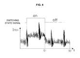
- FIG. 4 is a view illustrating an example of a first discharge signal
- FIG. 5 is a view to explain a process of a discharge signal separation unit separating a second discharge signal from a first discharge signal using a third discharge signal;
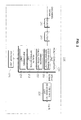
- FIG. 6 is a flowchart illustrating a method for evaluating health of a tab changer according to an exemplary embodiment
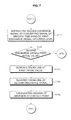
- FIG. 7 is a flowchart to explain operations S640 and S650 of FIG. 6 in detail.
- FIG. 1 is a view illustrating a system for evaluating health of a tab changer according to an exemplary embodiment.
- the system for evaluating the health of the tab changer includes a transformer 100 and a health evaluating apparatus 200.
- the transformer 100 is an electric power transformer and can level a transmission voltage up or down to a voltage desirable for a house or an electric power customer.
- the transformer 100 may include a tab changer 110, an output voltage detector 120, and a tab changer controller 130.
- the transformer 100 may be physically divided into a tab changer tank and a main tank.
- the tab changer 110 may correspond to the tab changer tank, and a block comprising a primary coil, a secondary coil, the output voltage detector 120, and the tab changer controller 130 to convert a voltage may correspond to the main tank.
- the tab changer tank and the main tank may be divided by a partition.
- the tab changer 110 is mounted in the transformer 100 to adjust an output voltage of the transformer 100 and may be an on load tap changer (OLTC).
- the tab changer 110 adjusts the output voltage of the secondary coil by performing tab switching automatically in response to a variation of a voltage applied to the primary coil, so that the output voltage of the secondary coil is maintained within an output voltage error range.
- the output voltage error range may be 1% to 10% of an applied voltage, for example.
- the tab changer 110 may be electrically connected to the secondary coil.
- the output voltage varies according to the voltage applied to the primary coil.
- the tab changer 110 is disposed adjacent to the secondary coil. However, this is merely an example and the tab changer 110 may be disposed adjacent to the primary coil.
- the primary coil is connected to a line terminal 'a' and a neutral terminal 'b' and a high voltage is applied to the line terminal 'a'.
- the secondary coil is connected to a line terminal 'c' and a neutral terminal 'd' and a low voltage is output from the line terminal 'c'.
- the tab changer 110 may include a plurality of tabs 1 ⁇ 8 and a tab switching unit 111. If the tab switching unit 111 is switched from 'A' to 'B', at least one of tabs 1, 3, 5, 7 applies an electric current, thereby outputting a voltage.
- the tabs 1 to 8 are depicted in the shape of a switch, but it means that the tabs work by means of electricity. In practice, the tabs may be realized by an electric power element capable of outputting a voltage or an output lead bar physically contacting an electric power element.
- the output voltage detector 120 detects the output voltage output from the secondary coil after a voltage is applied to the primary coil, and outputs the output voltage to the tab changer controller 130.
- the tab changer controller 130 may control a tab switching operation of the tab changer 110 using the output voltage output from the output voltage detector 120.
- the tab changer controller 130 may include a relay unit 131 and a controller 133.
- the relay unit 131 converts the output voltage output from the output voltage detector 120 into an electric current or a resistance value, and outputs the converted electric current or resistance value to the controller 133 and the health evaluating apparatus 200.
- the controller 133 compares the applied voltage of the transformer 100, i.e., the voltage applied to the primary coil, and the output voltage from the output voltage detector 120, and controls the tab switching of the tab changer 110 so that the output voltage is maintained within the output voltage error range. For example, if the output voltage detected when the tab 1 is in an on-state is out of the output voltage error range, the controller 133 may control the tab switching unit 111 to switch the tab of the tab changer 110 from the tab 1 to a different suitable tab.
- the health evaluating apparatus 200 evaluates health of the tab changer 110 which is used to adjust the output voltage of the transformer 100. If the tab switching unit 111 switches the tabs, a degree of abrasion at contact points of the tabs 1 to 8 changes according to an amount of load of the transformer 100. Therefore, the health evaluating apparatus 200 calculates the degree of abrasion at the contact points of the tabs 1 to 8 based on a discharge signal of the transformer 100 on a real time basis, and evaluates health of each of the tabs 1 to 8. This is to prevent damage to the tab changer 110 or an accident such as a blackout, which may occur as the degree of abrasion at the contact points exceeds a specific load factor.
- FIG. 2 is a block diagram illustrating a health evaluating apparatus according to an exemplary embodiment.
- the health evaluating apparatus 200 includes a storage unit 210, a tab state determination unit 220, a sensor 230, a filter 240, and a health evaluation unit 250.
- the storage unit 210 may store a first initial value l 1 and a second initial value l 2 that the health evaluating apparatus 200 uses to determine a degree of abrasion of each of the tabs 1 to 8.
- the first initial value l 1 is a discharge signal that is generated in the tab changer 110 and is initially measured when a switching state of the tab changer 110 is 'on' after the transformer 100 has been installed.
- the first initial value l 1 may have a form shown in FIG. 3A . If the switching state of the tab changer 110 is 'off', the discharge signal is rarely generated in the tab changer 110. As a time elapses, the discharge signal which is generated when the switching state of the tab changer 110 is 'on' has a form similar to that of the first initial value l 1 but its amplitude may be changeable.
- the second initial value l 2 is a discharge signal that is generated in the transformer 100 and is initially measured when the switching state of the tab changer 110 is 'off' after the transformer 100 has been installed. If input electric power uses a frequency of 60Hz, a frequency of 120Hz is output during a first period (t 1 ). Also, if the input electric power uses a frequency of 50Hz, a frequency of 100Hz is output during the first period (t 1 ).
- the second initial value l 2 may be used as an example of a third discharge signal, which will be described below.
- the second initial value l 2 is a discharge signal that is initially generated in the main tank of the transformer 100.
- an initial discharge signal generated in the transformer 100 is referred to as the second initial value l 2 for convenience of explanation. Accordingly, the second initial value l 2 does not include a discharge signal that is generated in the tab changer 110, as shown in FIG. 3B .
- the storage unit 210 accumulatively stores results of determining health of the tabs 1 to 8 by the tab changer 110.
- the result of determining the health indicates the degree of abrasion of each of the tabs 1 to 8 determined by a health determination unit 253, and may be stored along with a time at which the health is evaluated and discharge signals used for evaluating the health.
- the tab state determination unit 220 obtains a determination signal to determine whether the tab changer 110 is switched or not and determines whether the tab changer 100 is switched or not based on the determination signal.
- the tab changer 110 is switched if a tab to apply an electric current is changed.
- the determination signal may be a current I or a resistance R input from the relay unit 131.
- the tab state determination unit 220 determines whether the tab changer 110 is switched or not based on the current I or the resistance R input from the relay unit 131. It is determined that the tab changer 110 is switched (i.e., that the switching state is 'on'), if the tab switching unit 111 is switched from position 'A' to position 'B'. Also, it is determined that the tab changer 110 is not switched (i.e., that the switching stat is 'off'), if the tab switching unit 111 is in position 'A' or 'B'.
- the current I may have a value between 0 and 20mA. If the input current I is 0, the tab state determination unit 220 determines that the first tab is switched, and, if a current of about 1.176mA is input, the tab state determination unit 220 determines that the second tab is switched. If a current of 20mA is input, the tab state determination unit 220 determines that the 17 th tab is switched.
- the resistance R may have a value between 0 and 1600hm. If the input resistance R is 0, the tab state determination unit 220 determines that the first tab is switched, and, if a resistance of about 100hm is input, the tab state determination unit 220 determines that the second tab is switched. If a resistance of 160 Ohm is input, the tab state determination unit 220 determines that the 17 th tab is switched.
- the sensor 230 measures a discharge signal (hereinafter, referred to as a first discharge signal I PD1 ) generated in the transformer 100. Since the tab changer 110 performs tab switching periodically or aperiodically, the first discharge signal l PD1 is changed according to whether the switching state is 'on' or 'off' as shown in FIG. 4 . Referring to FIG. 4 , if the switching state of the tab changer 110 is 'on', the first discharge signal l PD1 is a mixture signal in which a discharge signal generated in the tab changer 110 and a discharge signal generated in the transformer 100 are mixed. If the switching state is 'off', the first discharge signal l PD1 is a discharge signal generated in the transformer 100.
- the sensor 230 may use a high frequency current transformer (HFCT), which measures a high frequency current flowing in a grounded line of the tab changer 110 or the transformer 100 as the first discharge signal (l PD1 ).
- HFCT high frequency current transformer
- the filter 240 filters a signal of a specific frequency band from the first discharge signal l PD1 output from the sensor 230, thereby removing signals except for the signal of the specific frequency band.
- the filter 240 may be a band pass filter.
- the health evaluation unit 250 separates a discharge signal (hereinafter, referred to as a second discharge signal l PD2 ) generated in the tab changer 110 from the first discharge signal I PD1 output from the sensor 230 or the filter 240, and compares the second discharge signal I PD2 and the pre-stored first initial value l 1 , thereby evaluating the health of the tab changer 110.
- a discharge signal hereinafter, referred to as a second discharge signal l PD2
- the health evaluation unit 250 separates a discharge signal (hereinafter, referred to as a second discharge signal l PD2 ) generated in the tab changer 110 from the first discharge signal I PD1 output from the sensor 230 or the filter 240, and compares the second discharge signal I PD2 and the pre-stored first initial value l 1 , thereby evaluating the health of the tab changer 110.
- the health evaluation unit 250 may include a discharge signal separation unit 251, an abrasion calculation unit 252, a health determination unit 253, and an informing unit 254.
- the discharge signal separation unit 251 separates the second discharge signal l PD2 from the first discharge signal l PD1 using a transformer discharge signal (hereinafter, referred to as a third discharge signal l PD3 ) measured if the tab changer 110 is not switched. If the tab state determination unit 220 determines that the tab changer 110 is switched, the discharge signal separation unit 251 separates the second discharge signal l PD2 while the tab changer 110 is switched. Information on a time during which the tab changer 110 is switched may be provided from a controller 233, and the discharge signal separation unit 251 may separate the second discharge signal l PD2 corresponding to the time.
- a transformer discharge signal hereinafter, referred to as a third discharge signal l PD3
- FIG. 5 is a view to explain a process of the discharge signal separation unit 251 separating the second discharge signal l PD2 from the first discharge signal l PD1 using the third discharge signal l PD3 .
- the specific time band T n is a time band in which the third discharge signal l PD3 is greater than or equal to a threshold value l th , and for example, is denoted by T1, T2, T3 in FIG. 5 .
- the threshold value l th may be set by a user or an administrator.
- a waveform signal indicates the third discharge signal l PD3 and a sold line, which is a trend line, is derived using a mathematical tool such as a Rhind Mathematical Papyrus (RMP).
- RMP Rhind Mathematical Papyrus
- the third discharge signal l PD3 used for separating the second discharge signal l PD2 may be any one of the following four signals:
- the abrasion calculation unit 252 compares the second discharge signal l PD2 separated by the discharge signal separation unit 251 and the pre-stored first initial value l 1 , and, if the second discharge signal l PD2 is greater than the first initial value l 1 , the abrasion calculation unit 252 calculates a degree of abrasion of a corresponding tab. This is because the fact that the second discharge signal l PD2 is greater than the first initial value l 1 means that the discharge signal generated in the tab changer 110 exceeds a reference value and thus a serious degree of abrasion occurs.
- the abrasion calculation unit 252 applies a reduced multivariate polynomial (RMP) model to the separated second discharge signal l PD2 and the first initial value l 1 , thereby deriving a trend line of the second discharge signal l PD2 and a trend line of the first initial value l 1 .
- the abrasion calculation unit 252 calculates a ratio of the trend line of the second discharge signal l PD2 to the trend line of the first initial value l 1 as the degree of abrasion at the contact point of the tab.
- Equation 1 used for calculating the degree of abrasion at the contact point is merely an example and the calculating of the degree of abrasion is not limited to equation 1.
- the health determination unit 253 determines health of the tab changer 110 or health of the corresponding tab based on the calculated degree of abrasion. For example, if the degree of abrasion is greater than a pre-set reference value, the health determination unit 253 determines that the degree of abrasion at the contact point is serious.
- the informing unit 254 may inform the user or administrator of at least one of the degree of abrasion at the contact point and the health of the tab changer 110.
- the informing unit 254 informs in various ways such as using a short message service (SMS) or emailing.
- SMS short message service
- FIG. 6 is a flowchart illustrating a method for evaluating health of a tab changer according to an exemplary embodiment.
- An apparatus performing the method for evaluating the health of the tab changer of FIG. 6 may be the health evaluating apparatus 200 described above with reference to FIGS. 1 and 2 or a health evaluating processor.
- the apparatus measures and stores a first initial value and a second initial value, if a transformer is installed.
- the first initial value is a discharge signal that is generated in the tab changer and initially measured in an on-switching state of the tab changer after the transformer has been installed, and may have a form as shown in FIG. 3A .
- the second initial value is a discharge signal that is generated in the transformer and initially measured in an off-switching state of the tab changer after the transformer has been installed, and may have a form as shown in FIG. 3B
- the apparatus determines whether the tab changer is switched or not.
- the apparatus may determine whether the tab changer is switched or not using a current or a resistance converted from an output voltage of the transformer.
- the switching state of tab changer is 'on', and if the tab changer is not switched, the switching state of the tab changer is 'off'.
- the apparatus may filter a first discharge signal which is measured by a sensor such as a high frequency current transformer (HFCT).
- the first discharge signal may be a mixture signal in which a discharge signal generated in the tab changer in the on-switching state of the tab changer is mixed with a discharge signal generated in the transformer, and may have a form as shown in FIG. 4 .
- the apparatus separates a second discharge signal from the first discharge signal in operation S640.
- the separated second discharge signal may have a form as shown in FIG. 5 .
- the apparatus compares the second discharge signal and the first initial value, thereby evaluating health of the tab changer.
- the apparatus compares a degree of abrasion at a contact point which is calculated in operation S650 (i.e., health of a corresponding tab of the tab changer) and a reference value.
- the apparatus informs an administrator of the transformer that the degree of abrasion is serious.
- the apparatus determines that the tab changer of the transformer is in a normal state and returns to operation S610.
- the apparatus compares a fourth discharge signal and the second initial value in operation S690.
- the fourth discharge signal may be a discharge signal of the first discharge signal that is generated in the transformer in the off-switching state of the tab changer and may be a signal that is measured during the time t 1 to t 2 of FIG. 4 .
- the apparatus may store the fourth discharge signal instead of the second initial value stored in operation 600.
- FIG. 7 is a flowchart illustrating operations S640 and S650 of FIG. 6 in detail.
- the apparatus separates the second discharge signal from the first discharge signal by converting a signal of the first discharge signal that corresponds to a specific time band into a zero level.
- the specific time band is a time band in which the third discharge signal is greater than or equal to a threshold value.
- the apparatus compares the second discharge signal and the first initial value.
- the apparatus drives a trend line of the first initial value using an RMP model in operation S730.
- the apparatus derives a trend line of the second discharge signal in operation S740.
- the apparatus calculates a degree of abrasion at a contact point of the tab changer (or a corresponding tab having generated the first discharge signal) based on a ratio of the second discharge signal to the first initial value.
- the configuration of the transformer shown in FIG. 1 is merely an example and the present disclosure is not limited to the configuration of the transformer of FIG. 1 .
- 8 tabs are provided in FIG. 1 , but other number of tabs may be provided.
- the tab changer 110 is installed adjacent to the secondary coil. However, this is merely an example and the tab changer 110 may be installed adjacent to the primary coil.
- the sensor 230 is included in the health evaluating apparatus 200.
- the sensor 230 may be provided separately from the health evaluating apparatus 200.
- a result of sensing by the sensor 230 may be transmitted to the health evaluating apparatus 200 in a wired or wireless manner.
- the health evaluating apparatus 200 includes the filter 240 in the above exemplary embodiment, but may not include the filter 240 in some situation.
- the health evaluation unit 250 may be realized in the form of hardware and/or software, and the signals illustrated in FIGS. 3 to 5 are merely an example and may have different forms.
- the degree of abrasion at the contact point of the tab changer provided in the transformer can be calculated based on the discharge signal that is generated according to the switching state of the tab changer, and the health of the tab changer can be monitored based on the degree of abrasion. Also, as the degree of abrasion or the health is accumulatively stored for every tab, the health of the tab changer can be continuously checked. Also, an abnormal condition is detected in early stages so that the transformer can stably work and an accident such as a blackout can be prevented beforehand.
Landscapes
- Physics & Mathematics (AREA)
- General Physics & Mathematics (AREA)
- Testing Relating To Insulation (AREA)
- Protection Of Transformers (AREA)
- Gas-Insulated Switchgears (AREA)
- Testing Electric Properties And Detecting Electric Faults (AREA)
Applications Claiming Priority (1)
| Application Number | Priority Date | Filing Date | Title |
|---|---|---|---|
| KR1020100138861A KR101037323B1 (ko) | 2010-12-30 | 2010-12-30 | 탭 체인저의 건전성 평가 장치 및 방법 |
Publications (2)
| Publication Number | Publication Date |
|---|---|
| EP2472274A2 true EP2472274A2 (de) | 2012-07-04 |
| EP2472274A3 EP2472274A3 (de) | 2013-12-04 |
Family
ID=44366663
Family Applications (1)
| Application Number | Title | Priority Date | Filing Date |
|---|---|---|---|
| EP11179122.4A Withdrawn EP2472274A3 (de) | 2010-12-30 | 2011-08-29 | Vorrichtung und Verfahren zur Beurteilung des Zustands eines Stufenschalters |
Country Status (5)
| Country | Link |
|---|---|
| US (1) | US20120173180A1 (de) |
| EP (1) | EP2472274A3 (de) |
| KR (1) | KR101037323B1 (de) |
| CA (1) | CA2750356A1 (de) |
| WO (1) | WO2012091241A1 (de) |
Cited By (4)
| Publication number | Priority date | Publication date | Assignee | Title |
|---|---|---|---|---|
| AT516004A1 (de) * | 2014-07-02 | 2016-01-15 | Omicron Electronics Gmbh | Verfahren und Vorrichtung zum Prüfen eines Stufenschalters eines Transformators |
| CN108351383A (zh) * | 2015-11-10 | 2018-07-31 | 奥幂电子有限公司 | 用电池运行的继电器测试设备1 |
| CN110609228A (zh) * | 2019-09-17 | 2019-12-24 | 国网河北省电力有限公司 | 电力变压器有载调压开关故障检测及校验装置 |
| AT521563A1 (de) * | 2018-07-26 | 2020-02-15 | Omicron Electronics Gmbh | Prüfvorrichtung, Verfahren und System zum Prüfen eines Mehrphasen-Stufenschalters eines Mehrphasen-Transformators |
Families Citing this family (9)
| Publication number | Priority date | Publication date | Assignee | Title |
|---|---|---|---|---|
| CN104237785B (zh) * | 2014-10-14 | 2017-05-03 | 广州市德百顺电气科技有限公司 | 干式变压器有载分接开关测试仪及其方法 |
| KR101652835B1 (ko) * | 2016-01-18 | 2016-09-01 | 주식회사프로컴시스템 | Oltc탭 선택기 접속부 소손 감시장치 |
| EP3288134B1 (de) * | 2016-08-26 | 2020-06-24 | ABB Power Grids Switzerland AG | Überwachung eines transformators mit einem stufenschalter |
| KR102697209B1 (ko) * | 2016-11-04 | 2024-08-22 | 한국전력공사 | 변압기 oltc 진단 장치 및 그 방법, 이의 부분 방전 진단 방법 |
| CN109541455A (zh) * | 2018-12-03 | 2019-03-29 | 国网江苏省电力有限公司南京供电分公司 | 一种基于s变换时频谱svd降噪的oltc冲击特性提取方法 |
| CN110658445B (zh) * | 2019-09-02 | 2021-06-01 | 红相股份有限公司 | 一种有载分接开关机械故障的分析诊断方法 |
| KR102235052B1 (ko) * | 2019-09-26 | 2021-04-01 | 한국전력공사 | Oltc 동작 분석 장치 및 그 방법 |
| CN110703086B (zh) * | 2019-11-12 | 2021-08-17 | 国网河南省电力公司南阳供电公司 | 存储有故障检测程序的计算机可读介质 |
| KR102389344B1 (ko) * | 2021-08-13 | 2022-04-22 | 주식회사 프로컴시스템 | 오엘티씨 탭 절환기의 천이저항 접촉 패드 마모 감시 장치 |
Citations (1)
| Publication number | Priority date | Publication date | Assignee | Title |
|---|---|---|---|---|
| KR20100138861A (ko) | 2010-12-13 | 2010-12-31 | 김창용 | 씽크대 인테리어 필름 |
Family Cites Families (13)
| Publication number | Priority date | Publication date | Assignee | Title |
|---|---|---|---|---|
| JPH05267077A (ja) * | 1992-03-19 | 1993-10-15 | Mitsubishi Electric Corp | 負荷時タップ切換変圧器 |
| JP3187642B2 (ja) * | 1994-02-25 | 2001-07-11 | 関西電力株式会社 | 電気機器の異常検出方法及び回転電機の異常検出装置 |
| DE19530776C1 (de) * | 1995-08-22 | 1996-12-12 | Reinhausen Maschf Scheubeck | Verfahren zur Überwachung eines Lastumschalters für einen Stufenschalter |
| SE510450C2 (sv) * | 1996-03-11 | 1999-05-25 | Abb Research Ltd | Förfarande för övervakning av lindningskopplare genom ljudanalys |
| JPH11345716A (ja) * | 1998-06-02 | 1999-12-14 | Takaoka Electric Mfg Co Ltd | 負荷時タップ切換変圧器の漏油検出方法およびその装置 |
| US7145760B2 (en) * | 2000-12-15 | 2006-12-05 | Abb Technology Ltd. | Tap changer monitoring |
| KR100449891B1 (ko) * | 2001-09-20 | 2004-09-22 | 금호타이어 주식회사 | 트럭버스용 타이어의 트레드 고무조성물 |
| KR100404669B1 (en) | 2003-06-11 | 2003-11-10 | Ssang Yong Electric Co Ltd | Apparatus for switching tab |
| KR200328640Y1 (ko) | 2003-07-18 | 2003-09-29 | 한국전력공사 | 주상변압기의 무정전용 탭조절 기구 |
| JP4627695B2 (ja) * | 2005-07-27 | 2011-02-09 | 三菱電機株式会社 | 負荷時タップ切換器の監視装置 |
| KR20090019442A (ko) * | 2007-08-21 | 2009-02-25 | 주식회사유성계전 | 주변압기 병렬운전용 자동전압 조정장치 및 그 방법 |
| JP5472846B2 (ja) * | 2008-12-16 | 2014-04-16 | 三菱電機株式会社 | タップ切換装置および気圧調整方法 |
| EP2244272B1 (de) * | 2009-04-20 | 2012-06-06 | ABB Technology Ltd | Messung der Kontaktsequenz in einem Stufenschalter |
-
2010
- 2010-12-30 KR KR1020100138861A patent/KR101037323B1/ko not_active Expired - Fee Related
-
2011
- 2011-07-22 WO PCT/KR2011/005406 patent/WO2012091241A1/ko not_active Ceased
- 2011-08-12 US US13/208,810 patent/US20120173180A1/en not_active Abandoned
- 2011-08-24 CA CA2750356A patent/CA2750356A1/en not_active Abandoned
- 2011-08-29 EP EP11179122.4A patent/EP2472274A3/de not_active Withdrawn
Patent Citations (1)
| Publication number | Priority date | Publication date | Assignee | Title |
|---|---|---|---|---|
| KR20100138861A (ko) | 2010-12-13 | 2010-12-31 | 김창용 | 씽크대 인테리어 필름 |
Cited By (6)
| Publication number | Priority date | Publication date | Assignee | Title |
|---|---|---|---|---|
| AT516004A1 (de) * | 2014-07-02 | 2016-01-15 | Omicron Electronics Gmbh | Verfahren und Vorrichtung zum Prüfen eines Stufenschalters eines Transformators |
| AT516004B1 (de) * | 2014-07-02 | 2017-04-15 | Omicron Electronics Gmbh | Verfahren und Vorrichtung zum Prüfen eines Stufenschalters eines Transformators |
| CN108351383A (zh) * | 2015-11-10 | 2018-07-31 | 奥幂电子有限公司 | 用电池运行的继电器测试设备1 |
| AT521563A1 (de) * | 2018-07-26 | 2020-02-15 | Omicron Electronics Gmbh | Prüfvorrichtung, Verfahren und System zum Prüfen eines Mehrphasen-Stufenschalters eines Mehrphasen-Transformators |
| AT521563B1 (de) * | 2018-07-26 | 2025-05-15 | Omicron Electronics Gmbh | Prüfvorrichtung, Verfahren und System zum Prüfen eines Mehrphasen-Stufenschalters eines Mehrphasen-Transformators |
| CN110609228A (zh) * | 2019-09-17 | 2019-12-24 | 国网河北省电力有限公司 | 电力变压器有载调压开关故障检测及校验装置 |
Also Published As
| Publication number | Publication date |
|---|---|
| CA2750356A1 (en) | 2012-06-30 |
| KR101037323B1 (ko) | 2011-05-26 |
| EP2472274A3 (de) | 2013-12-04 |
| US20120173180A1 (en) | 2012-07-05 |
| WO2012091241A1 (ko) | 2012-07-05 |
Similar Documents
| Publication | Publication Date | Title |
|---|---|---|
| EP2472274A2 (de) | Vorrichtung und Verfahren zur Beurteilung des Zustands eines Stufenschalters | |
| KR102798124B1 (ko) | 변압기 탭절환 시험 방법, 권선비 시험 방법 | |
| CA2707552C (en) | Battery system and management method | |
| KR101869561B1 (ko) | 회로 보호 장치 및 테스트 회로 | |
| US10495692B2 (en) | Battery monitor | |
| CN105301424A (zh) | 具有集成鲁棒性检查和平衡故障检测的连续泄露检测电路 | |
| US9806383B2 (en) | Electric energy storage device and method for operating an electric energy storage device | |
| JP5263819B2 (ja) | 蓄電池監視システム | |
| GB2566308A (en) | Battery management system | |
| WO2013027327A1 (ja) | 蓄電池状態通知システム、蓄電池状態通知方法、および、蓄電池状態通知プログラム | |
| JPWO2019150586A1 (ja) | 集中電圧制御装置および集中電圧制御システム | |
| KR20100132316A (ko) | 블랙박스 기능을 갖춘 전력 품질 관리 장치 및 방법, 그리고 부하별 전력 사용량 분석 장치 | |
| US9581646B2 (en) | Electrical arc detection in electrical switching devices | |
| KR20120136952A (ko) | 고저항 지락고장 검출 시스템 및 그 방법 | |
| MXPA06002635A (es) | Monitor para ciclo de trabajo y derivacion para mantenimiento preventivo para un regulador de voltaje. | |
| KR20170019091A (ko) | 현장용 지상개폐기 진단기록장치 | |
| WO2015008412A1 (ja) | 保護制御システムおよびインタフェース装置 | |
| KR100941962B1 (ko) | 접지상태를 판단할 수 있는 서지보호기 | |
| KR101498978B1 (ko) | 자계 변환 전원 공급 장치 | |
| KR20240000990A (ko) | 배전설비의 누설전류 모니터링 장치 및 누설전류 모니터링 방법 | |
| US10186369B2 (en) | Electric system with control winding and method of adjusting same | |
| JP4627489B2 (ja) | 無停電電源システム及びバッテリの充電方法 | |
| JP7248421B2 (ja) | 真空遮断器システムおよび真空遮断器の異常診断方法 | |
| KR101598474B1 (ko) | 다중 역률제어 기반 수배전반 | |
| KR101232556B1 (ko) | Scada를 이용한 자동 전압 조절 장치 및 그 방법 |
Legal Events
| Date | Code | Title | Description |
|---|---|---|---|
| 17P | Request for examination filed |
Effective date: 20110829 |
|
| AK | Designated contracting states |
Kind code of ref document: A2 Designated state(s): AL AT BE BG CH CY CZ DE DK EE ES FI FR GB GR HR HU IE IS IT LI LT LU LV MC MK MT NL NO PL PT RO RS SE SI SK SM TR |
|
| AX | Request for extension of the european patent |
Extension state: BA ME |
|
| PUAI | Public reference made under article 153(3) epc to a published international application that has entered the european phase |
Free format text: ORIGINAL CODE: 0009012 |
|
| PUAL | Search report despatched |
Free format text: ORIGINAL CODE: 0009013 |
|
| STAA | Information on the status of an ep patent application or granted ep patent |
Free format text: STATUS: THE APPLICATION HAS BEEN WITHDRAWN |
|
| AK | Designated contracting states |
Kind code of ref document: A3 Designated state(s): AL AT BE BG CH CY CZ DE DK EE ES FI FR GB GR HR HU IE IS IT LI LT LU LV MC MK MT NL NO PL PT RO RS SE SI SK SM TR |
|
| AX | Request for extension of the european patent |
Extension state: BA ME |
|
| RIC1 | Information provided on ipc code assigned before grant |
Ipc: G01R 31/02 20060101AFI20131025BHEP Ipc: G01R 31/12 20060101ALI20131025BHEP Ipc: G01R 31/327 20060101ALI20131025BHEP |
|
| 18W | Application withdrawn |
Effective date: 20131030 |