EP2472338A2 - Bilderzeugungsvorrichtung - Google Patents
Bilderzeugungsvorrichtung Download PDFInfo
- Publication number
- EP2472338A2 EP2472338A2 EP11195810A EP11195810A EP2472338A2 EP 2472338 A2 EP2472338 A2 EP 2472338A2 EP 11195810 A EP11195810 A EP 11195810A EP 11195810 A EP11195810 A EP 11195810A EP 2472338 A2 EP2472338 A2 EP 2472338A2
- Authority
- EP
- European Patent Office
- Prior art keywords
- waste toner
- retainer
- main body
- image formation
- latching
- Prior art date
- Legal status (The legal status is an assumption and is not a legal conclusion. Google has not performed a legal analysis and makes no representation as to the accuracy of the status listed.)
- Granted
Links
Images








Classifications
-
- G—PHYSICS
- G03—PHOTOGRAPHY; CINEMATOGRAPHY; ANALOGOUS TECHNIQUES USING WAVES OTHER THAN OPTICAL WAVES; ELECTROGRAPHY; HOLOGRAPHY
- G03G—ELECTROGRAPHY; ELECTROPHOTOGRAPHY; MAGNETOGRAPHY
- G03G21/00—Arrangements not provided for by groups G03G13/00 - G03G19/00, e.g. cleaning, elimination of residual charge
- G03G21/16—Mechanical means for facilitating the maintenance of the apparatus, e.g. modular arrangements
-
- G—PHYSICS
- G03—PHOTOGRAPHY; CINEMATOGRAPHY; ANALOGOUS TECHNIQUES USING WAVES OTHER THAN OPTICAL WAVES; ELECTROGRAPHY; HOLOGRAPHY
- G03G—ELECTROGRAPHY; ELECTROPHOTOGRAPHY; MAGNETOGRAPHY
- G03G21/00—Arrangements not provided for by groups G03G13/00 - G03G19/00, e.g. cleaning, elimination of residual charge
- G03G21/16—Mechanical means for facilitating the maintenance of the apparatus, e.g. modular arrangements
- G03G21/1604—Arrangement or disposition of the entire apparatus
- G03G21/1623—Means to access the interior of the apparatus
- G03G21/1633—Means to access the interior of the apparatus using doors or covers
-
- G—PHYSICS
- G03—PHOTOGRAPHY; CINEMATOGRAPHY; ANALOGOUS TECHNIQUES USING WAVES OTHER THAN OPTICAL WAVES; ELECTROGRAPHY; HOLOGRAPHY
- G03G—ELECTROGRAPHY; ELECTROPHOTOGRAPHY; MAGNETOGRAPHY
- G03G21/00—Arrangements not provided for by groups G03G13/00 - G03G19/00, e.g. cleaning, elimination of residual charge
- G03G21/10—Collecting or recycling waste developer
-
- G—PHYSICS
- G03—PHOTOGRAPHY; CINEMATOGRAPHY; ANALOGOUS TECHNIQUES USING WAVES OTHER THAN OPTICAL WAVES; ELECTROGRAPHY; HOLOGRAPHY
- G03G—ELECTROGRAPHY; ELECTROPHOTOGRAPHY; MAGNETOGRAPHY
- G03G21/00—Arrangements not provided for by groups G03G13/00 - G03G19/00, e.g. cleaning, elimination of residual charge
- G03G21/10—Collecting or recycling waste developer
- G03G21/105—Arrangements for conveying toner waste
-
- G—PHYSICS
- G03—PHOTOGRAPHY; CINEMATOGRAPHY; ANALOGOUS TECHNIQUES USING WAVES OTHER THAN OPTICAL WAVES; ELECTROGRAPHY; HOLOGRAPHY
- G03G—ELECTROGRAPHY; ELECTROPHOTOGRAPHY; MAGNETOGRAPHY
- G03G21/00—Arrangements not provided for by groups G03G13/00 - G03G19/00, e.g. cleaning, elimination of residual charge
- G03G21/10—Collecting or recycling waste developer
- G03G21/12—Toner waste containers
-
- G—PHYSICS
- G03—PHOTOGRAPHY; CINEMATOGRAPHY; ANALOGOUS TECHNIQUES USING WAVES OTHER THAN OPTICAL WAVES; ELECTROGRAPHY; HOLOGRAPHY
- G03G—ELECTROGRAPHY; ELECTROPHOTOGRAPHY; MAGNETOGRAPHY
- G03G21/00—Arrangements not provided for by groups G03G13/00 - G03G19/00, e.g. cleaning, elimination of residual charge
- G03G21/16—Mechanical means for facilitating the maintenance of the apparatus, e.g. modular arrangements
- G03G21/1642—Mechanical means for facilitating the maintenance of the apparatus, e.g. modular arrangements for connecting the different parts of the apparatus
- G03G21/1647—Mechanical connection means
-
- G—PHYSICS
- G03—PHOTOGRAPHY; CINEMATOGRAPHY; ANALOGOUS TECHNIQUES USING WAVES OTHER THAN OPTICAL WAVES; ELECTROGRAPHY; HOLOGRAPHY
- G03G—ELECTROGRAPHY; ELECTROPHOTOGRAPHY; MAGNETOGRAPHY
- G03G21/00—Arrangements not provided for by groups G03G13/00 - G03G19/00, e.g. cleaning, elimination of residual charge
- G03G21/16—Mechanical means for facilitating the maintenance of the apparatus, e.g. modular arrangements
- G03G21/1661—Mechanical means for facilitating the maintenance of the apparatus, e.g. modular arrangements means for handling parts of the apparatus in the apparatus
- G03G21/1671—Mechanical means for facilitating the maintenance of the apparatus, e.g. modular arrangements means for handling parts of the apparatus in the apparatus for the photosensitive element
-
- G—PHYSICS
- G03—PHOTOGRAPHY; CINEMATOGRAPHY; ANALOGOUS TECHNIQUES USING WAVES OTHER THAN OPTICAL WAVES; ELECTROGRAPHY; HOLOGRAPHY
- G03G—ELECTROGRAPHY; ELECTROPHOTOGRAPHY; MAGNETOGRAPHY
- G03G21/00—Arrangements not provided for by groups G03G13/00 - G03G19/00, e.g. cleaning, elimination of residual charge
- G03G21/16—Mechanical means for facilitating the maintenance of the apparatus, e.g. modular arrangements
- G03G21/18—Mechanical means for facilitating the maintenance of the apparatus, e.g. modular arrangements using a processing cartridge, whereby the process cartridge comprises at least two image processing means in a single unit
- G03G21/1839—Means for handling the process cartridge in the apparatus body
- G03G21/1842—Means for handling the process cartridge in the apparatus body for guiding and mounting the process cartridge, positioning, alignment, locks
-
- G—PHYSICS
- G03—PHOTOGRAPHY; CINEMATOGRAPHY; ANALOGOUS TECHNIQUES USING WAVES OTHER THAN OPTICAL WAVES; ELECTROGRAPHY; HOLOGRAPHY
- G03G—ELECTROGRAPHY; ELECTROPHOTOGRAPHY; MAGNETOGRAPHY
- G03G2221/00—Processes not provided for by group G03G2215/00, e.g. cleaning or residual charge elimination
- G03G2221/16—Mechanical means for facilitating the maintenance of the apparatus, e.g. modular arrangements and complete machine concepts
- G03G2221/1651—Mechanical means for facilitating the maintenance of the apparatus, e.g. modular arrangements and complete machine concepts for connecting the different parts
- G03G2221/1654—Locks and means for positioning or alignment
Definitions
- the present invention relates to an image formation apparatus.
- the present disclosure employs the following.
- FIGS. 8A and 8B are schematic diagrams showing a condition in which a reception opening b of a waste toner bottle B is attached to a delivery opening storing part 13.
- FIG. 8A is a planar view of the image formation apparatus seen from above.
- FIG. 8B is a cross sectional view of FIG. 7A along line X-X.
- a shutter part 13a is held by a delivery opening storing part 13 while being biased by a compression spring 13b in an opposite direction with respect to a direction in which the waste toner bottle B is equipped.
- the shutter part 13a covers a delivery opening 43 formed at a lower surface of a transport pipe 42.
- the shutter part 13a is formed by an opaque component.
- the shutter part 13a includes a lid part 13c covering the delivery opening 43, a contacting part 13d contacting the reception opening b of the waste toner bottle B, and a blocking part 13e blocking a full sensor 13f.
- the full sensor 13f is configured so that a light reception part detects light emitted by an illuminating part.
- the waste toner bottle B comprises a tank part 80 and a cap part 81 fixed at a head part of the tank part 80.
- the cap part 81 acts as a reception opening b.
- the cap part 81 is formed by a material having elasticity and transparency.
- the cap part 61 comprises a neck part 81a and a shoulder part 81b.
- the neck part 81a opposes a lower portion of the delivery opening 43 of the transport pipe 42.
- the shoulder part 81b engages with a tank part 80 at a lower portion of the neck part 81a.
- two knob parts 61c, 81d are provided so as to extend from a peripheral surface at opposing positions in the circumference direction. Meanwhile, a protrusion part 81e shaped like a wedge is formed on the knob part 81d.
- the shutter 13a moves toward the right direction in FIGS. 8A, 8B due to the compression spring 13b.
- the shutter 13a covers the delivery opening 43 of the transport pipe 42.
- the shutter part 13a contacts the neck part 81a, moves toward the left direction in opposition to the bias by the compression spring 13b, and retreats from the delivery opening 43.
- the neck part 61a is placed opposite the delivery opening 43.
- the protrusion part 81e of the knob part 61d engages with the latching part 13b formed on the delivery opening storing part 13.
- a movement toward the right direction is restricted.
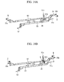
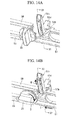
- FIGS. 12A, 12B are enlarged perspective views of a configuration including the latching chip 64a.
- the latching chip 64a rotates around the shaft 68 according to the rotation of the shaft 68.
- the wall part 69 provided on the main body 1 is provided so that a wall surface of the wall part 69 faces the latching chip 64a.
- the retainer R is locked
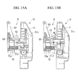
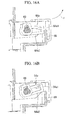
- the latching chip 64a is assembled with respect to the shaft 68 so that the tip 64a1 faces the wall part 69, as shown in FIG. 16A . Therefore, when the retainer R is locked and a retainer main body 60 is rotated in the direction of the arrow E, the latching chip 64a is latched by the wall part 69, thereby restraining the retainer main body 60.
- the retainer main body 60 may be rotated in the direction of the arrow E.
- the retainer main body 60 is returned to its original position, the retainer main body 60 is rotated in a direction opposite to the arrow E. At this time, the lower surface 64a2 of the latching chip 64a hits the upper end of the wall part 69. Thus, the tip 64a1 of the latching chip 64a is elevated. The tip 64a1 of the latching chip 64a is elevated until it is brought to a position above the wall part 69 according to the movement of the retainer main body 60. Further, when the tip 64a1 reaches a position above the wall part 69, the latching chip 64a rotates with its own weight to lower the tip 64a1. Thus, the retainer R is locked once again.
- the latching chip 64a side is configured in a same manner because the latching chip 64a and the latching chip 64b are bilaterally symmetric.
- a pushing part 70 is provided on the retainer main body 60.
- the pushing part 70 pushes the cover body 11 of the waste toner assembly 10 from a back side.
- a coil spring 70a is stored inside the pushing part 70.
- the pushing part pushes the waste toner assembly 10 from a back side while the waste toner assembly 10 is rotated in order to restore it from an opened condition to its original state.
- This pushing part 70 allows the retainer main body 60 to be returned reliably to a locked condition for the following reasons.
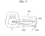
- the latching chip 64a (and the latching chip 64b in the same manner) rotates around the shaft 68 so as to elevate and lower the tip 64a1. Therefore, as described above, in order to place the latching chip 64a above the wall part 69 to return the retainer main body 60 to a locked condition, the maximum external part 64a3 (a part having the largest distance from the center of rotation O) of the latching chip 64a shown in FIG. 17 needs to come above the wall part 69. This distance L1 from the center of rotation O to the maximum external part 64a3 is longer than the distance L2 from the center of rotation O to the tip 64a1. Therefore, in order to return the retainer main body 60 to a locked condition, the retainer main body 60 needs to be pushed in once toward a rear side compared to a posture in the locked condition.
- the waste toner assembly 10 becomes locked when the latching chip 30b enters the opening 71 of the main body 1.
- the latching chip 30b comprises a sloped surface 30b1 facing the retainer R side.
- the latching chip 30b is gradually pushed in while the sloped surface 30b1 contacts the wall part 72 at the front of the opening 71.
- the tip 30b2 of the latching chip 30b comes above the wall part 72.
- the latching chip 30b enters the opening 71 of the main body 1 due to the biasing force of the spring 51a. Therefore, the waste toner assembly 10 may be returned to the locked condition by assuming the posture of the locked condition.
- the vibration that occurs when the latching chip 64a comes above the wall part 69 is conveyed to the user.
- This configuration applies to the latching chip 64b as well. In this way, the user is able to know that the retainer main body 60 is in a locked condition. Therefore, the retainer main body 60 may be returned to a locked condition in a reliable manner without any specific problems.
- the latching chip 30b enters the opening 71 when the waste toner assembly 10 reaches a posture of the locked condition.
- This configuration applies to the latching chip 30a as well.
- the waste toner assembly 10 becomes locked before the retainer main body 60. Therefore, due to the vibration that occurs when the latching chip 30b enters the opening 71, the user might mistakenly believe that the retainer main body 60 is locked as well. As a result, the retainer main body 60 is not in a locked condition, and an image formation cannot be commenced.
- a pushing part 70 is provided.
- the waste toner assembly 10 is pushed back with a greater force.
- the user will be pushing in the waste toner assembly 10 with a significant amount of force.
- the retainer main body 60 is adequately pushed into a rear side.
- the retainer main body 60 may be returned to the locked condition in a reliable manner.
- FIG. 19 is an enlarged perspective view of a latching chip 30b according to the present embodiment.
- a click part 73 is provided on the tip 30b2 of the latching chip 30b so that the click part 73 protrudes toward the front side of the copying machine.
- This click part 73 is integrally provided with the latching chip 30b at a back surface side of the sloped surface 30b1 which is a contacting surface with the wall part 72.
- the amount of protrusion L3 (the length of protrusion toward the wall part 72 side in a locked condition) from the latching chip 30b of the clock part 73 is set, according to the latching chip 64a, to be greater than or equal to the difference between the distance L1 from the center of rotation O of the maximum external component 64a and the distance L2 from the center of rotation O to the tip 64a1.
- This configuration applies to the latching chip 64b in a similar manner as well.
- the amount of protrusion L3 from the latching chip 30b is set, according to the latching chip 64a, to be greater than or equal to the difference between the distance L1 from the center of rotation O of the maximum external component 64a and the distance L2 from the center of rotation O to the tip 64a1.
- This configuration applies to the latching chip 64b in a similar manner. Therefore, when the user tries to lock both the waste toner assembly 10 and the retainer main body 60 at once, it is possible to prevent the waste toner assembly 10 from becoming locked first.
- the click part 73 acts to adjust the timing of locking at which the retainer main body 60 is locked before the waste toner assembly 10.
- the retainer main body 60 when the waste toner assembly 10 returns to a locked condition, the retainer main body 60 is also returned to a locked condition. Therefore, the retainer main body 60 may be returned to a locked condition in a reliable manner.
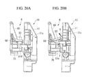
- the retainer main body 60 may be returned to a locked condition reliably by the click part 73. Therefore, as shown in FIG. 20 , the pushing part 70 described in the first embodiment does not include a coil spring 70a and is instead fixed.
- the pushing part 70 has a coil spring 70a, a biasing force is constantly applied to the waste toner assembly 10 in a locked condition.
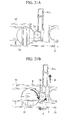
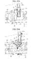
- FIGS. 21A and 21B are enlarged frontal diagrams of a configuration adjacent to a release lever 20 based on the present embodiment.
- the copying machine according to the present embodiment comprises a gear wheel 74 which is in gear with the release lever 20 and the retainer lever releasing part 51c.
- the sloped surface 51b is not provided to the connection rod 51.
- the connection rod 51 and the retainer release part 51c are not in contact with one another and are instead distanced from one another.
- the connection rods 50, 51 (the first transmission part) and the retainer release part 51c (the second transmission part) are placed so as to be distanced from one another.
- the connection rods 50, 51 transmit the power due to the rotation of the release lever 20 to the latching chips 30a, 30b.
- the retainer release part 51c transmits power due to the rotation of the release lever 20 to the latching chips 64a, 64b.
- the release lever 20 includes a click part at a back surface side, which is latched to the connection rod 51 and the connection rod 50 only when a rotation is made in the direction of the arrow S.
- the click part is not diagrammed.
- the click part is not latched to the connection rod 51.
- the connection rod 50 moves toward the left side in FIG. 21A due to an external force, the click part is not latched to the connection rod 50. Therefore, when the connection rods 50, 51 are moved due to an external force, the release lever 20 is not rotated.
- the release lever 20 is constantly biased toward an opposite direction with respect to the arrow S by a spring that is not diagrammed so that the release lever 20 returns to its original posture on its own.
- the release lever 20 is rotated in the direction of the arrow S.
- the gear wheel 74 rotates in a direction of the arrow F, and the retainer lever releasing part 51c moves upward via the gear wheel 74.
- connection rods 50, 51 move so that the latching chips 30a, 30b are pushed in.
- the connection rod 50, 51 and the retainer releasing part 51c are distanced. Therefore, the retainer release part 51c does not move upwards. Therefore, the retainer main body 60 will not act as a resistance to the pushing-in movement of the latching chips 30a, 30b. Thus, it is possible to reduce the load when the waste toner assembly 10 is returned to a locked condition.
- a wire 75 may be provided instead of the gear wheel 74.
- the wire 75 is emphasized to enhance visibility.
- An end of the wire 75 is connected to the release lever 20.
- the wire 75 is configured so that the wire 75 is rolled up by the release lever 20 as the release lever 20 rotates.
- protrusion parts 76, 77 are provided at an inner wall of the cover body 11 flanking the retainer release part 51c.
- the wire 75 is rolled up to the protrusion part 76 provided at a release lever 20 side from above, while the other end is fixed to the protrusion part 77 provided at an opposite side with respect to the release lever 20. Further, between the protrusion part 76 and the protrusion part 77, the wire 75 is placed so as to contact the bottom part of the retainer release part 51c.
- connection rods 50, 51 are distanced from the retainer release part 51c. Therefore, the retainer main body 60 will not act as a resistance to the pushing-in movement of the latching chip 30a, 30b. Therefore, it is possible to reduce the load when the waste toner assembly 10 is returned to a locked condition.
Landscapes
- Physics & Mathematics (AREA)
- General Physics & Mathematics (AREA)
- Engineering & Computer Science (AREA)
- Life Sciences & Earth Sciences (AREA)
- Environmental & Geological Engineering (AREA)
- Sustainable Development (AREA)
- Computer Vision & Pattern Recognition (AREA)
- Cleaning In Electrography (AREA)
- Dry Development In Electrophotography (AREA)
- Electrophotography Configuration And Component (AREA)
Applications Claiming Priority (3)
| Application Number | Priority Date | Filing Date | Title |
|---|---|---|---|
| JP2010292662A JP5323048B2 (ja) | 2010-12-28 | 2010-12-28 | 画像形成装置 |
| JP2010292661 | 2010-12-28 | ||
| JP2011216981A JP5690697B2 (ja) | 2010-12-28 | 2011-09-30 | 画像形成装置 |
Publications (3)
| Publication Number | Publication Date |
|---|---|
| EP2472338A2 true EP2472338A2 (de) | 2012-07-04 |
| EP2472338A3 EP2472338A3 (de) | 2015-02-25 |
| EP2472338B1 EP2472338B1 (de) | 2019-04-10 |
Family
ID=45497750
Family Applications (1)
| Application Number | Title | Priority Date | Filing Date |
|---|---|---|---|
| EP11195810.4A Active EP2472338B1 (de) | 2010-12-28 | 2011-12-27 | Bilderzeugungsvorrichtung |
Country Status (4)
| Country | Link |
|---|---|
| US (1) | US8787795B2 (de) |
| EP (1) | EP2472338B1 (de) |
| KR (1) | KR101292968B1 (de) |
| CN (1) | CN102566388B (de) |
Families Citing this family (13)
| Publication number | Priority date | Publication date | Assignee | Title |
|---|---|---|---|---|
| JP5934676B2 (ja) * | 2013-05-30 | 2016-06-15 | 京セラドキュメントソリューションズ株式会社 | 画像形成装置 |
| KR102048753B1 (ko) | 2013-10-25 | 2019-11-27 | 휴렛-팩커드 디벨롭먼트 컴퍼니, 엘.피. | 화상 형성장치 및 화상 형성장치의 메인티넌스 방법 |
| US9291992B1 (en) | 2014-12-19 | 2016-03-22 | Lexmark International, Inc. | Positional control features for an imaging unit in an electrophotographic image forming device |
| US9285758B1 (en) | 2014-12-19 | 2016-03-15 | Lexmark International, Inc. | Positional control features between replaceable units of an electrophotographic image forming device |
| US9411303B1 (en) * | 2015-04-10 | 2016-08-09 | Lexmark International, Inc. | Positioning stop assembly for a replaceable unit of an electrophotographic image forming device |
| JP7139655B2 (ja) * | 2018-03-30 | 2022-09-21 | ブラザー工業株式会社 | ドラムユニット |
| USD947277S1 (en) * | 2018-09-21 | 2022-03-29 | Konica Minolta, Inc. | Electronic copying machine |
| USD947276S1 (en) * | 2018-09-26 | 2022-03-29 | Konica Minolta, Inc. | Electronic copying machine |
| TWI688842B (zh) * | 2019-02-13 | 2020-03-21 | 上福全球科技股份有限公司 | 回收槽的碳粉偵測裝置 |
| JP7435123B2 (ja) * | 2020-03-25 | 2024-02-21 | 富士フイルムビジネスイノベーション株式会社 | 着脱式容器及びこれを用いた容器搭載装置 |
| JP7484298B2 (ja) * | 2020-03-26 | 2024-05-16 | 富士フイルムビジネスイノベーション株式会社 | 粉体処理装置 |
| JP7424161B2 (ja) * | 2020-03-26 | 2024-01-30 | 富士フイルムビジネスイノベーション株式会社 | 回収容器 |
| JP2024017142A (ja) * | 2022-07-27 | 2024-02-08 | 富士フイルムビジネスイノベーション株式会社 | 画像形成装置 |
Family Cites Families (20)
| Publication number | Priority date | Publication date | Assignee | Title |
|---|---|---|---|---|
| JPH065443B2 (ja) * | 1984-11-13 | 1994-01-19 | 三田工業株式会社 | 静電複写装置 |
| JP3369791B2 (ja) | 1995-05-15 | 2003-01-20 | 株式会社リコー | 画像形成装置 |
| JP3285741B2 (ja) | 1995-09-28 | 2002-05-27 | キヤノン株式会社 | カラー画像形成装置及びプロセスカートリッジ |
| US6674982B2 (en) | 2000-09-26 | 2004-01-06 | Ricoh Company, Ltd. | Image forming apparatus including components mounted and/or dismounted in selected order |
| JP2006011360A (ja) * | 2004-05-24 | 2006-01-12 | Ricoh Co Ltd | 画像形成装置及び廃トナーボトル脱着方法 |
| US7245868B2 (en) | 2004-05-24 | 2007-07-17 | Ricoh Company, Ltd. | Image forming apparatus and method of mounting and dismounting a waste toner bottle |
| JP4750403B2 (ja) | 2004-11-12 | 2011-08-17 | キヤノン株式会社 | 画像形成装置 |
| JP4794849B2 (ja) * | 2004-11-15 | 2011-10-19 | 京セラミタ株式会社 | 画像形成装置の廃トナー搬送機構 |
| JP2007219453A (ja) * | 2006-02-20 | 2007-08-30 | Toshiba Corp | 廃トナー回収装置及び画像形成装置 |
| JP4810305B2 (ja) * | 2006-05-15 | 2011-11-09 | キヤノン株式会社 | 画像形成装置 |
| JP2008304841A (ja) * | 2007-06-11 | 2008-12-18 | Kyocera Mita Corp | 画像形成装置 |
| US7831190B2 (en) * | 2007-07-04 | 2010-11-09 | Samsung Electronics Co., Ltd. | Cover opening and closing unit, image forming apparatus having the same, and method of removing and mounting cover |
| US8254823B2 (en) * | 2007-10-15 | 2012-08-28 | Ricoh Company, Ltd. | Waste toner storage unit and image forming apparatus using same |
| JP5206145B2 (ja) * | 2007-10-15 | 2013-06-12 | 株式会社リコー | 廃トナー回収容器ユニットおよび画像形成装置 |
| JP5053161B2 (ja) * | 2008-04-25 | 2012-10-17 | 京セラドキュメントソリューションズ株式会社 | 廃トナー回収装置、及びこれを備えた画像形成装置 |
| JP2009271276A (ja) | 2008-05-07 | 2009-11-19 | Ricoh Co Ltd | 廃トナー回収装置、これを用いた画像形成装置 |
| JP5110734B2 (ja) * | 2008-08-08 | 2012-12-26 | シャープ株式会社 | 画像形成装置 |
| JP5094645B2 (ja) | 2008-09-01 | 2012-12-12 | シャープ株式会社 | 画像形成装置 |
| JP5146218B2 (ja) | 2008-09-18 | 2013-02-20 | コニカミノルタビジネステクノロジーズ株式会社 | 画像形成装置 |
| JP5206402B2 (ja) | 2008-12-26 | 2013-06-12 | コニカミノルタビジネステクノロジーズ株式会社 | 廃棄粉体回収装置及びそれを備えた画像形成装置 |
-
2011
- 2011-12-15 CN CN201110434249.XA patent/CN102566388B/zh active Active
- 2011-12-20 KR KR1020110138251A patent/KR101292968B1/ko active Active
- 2011-12-27 US US13/337,586 patent/US8787795B2/en active Active
- 2011-12-27 EP EP11195810.4A patent/EP2472338B1/de active Active
Non-Patent Citations (1)
| Title |
|---|
| None |
Also Published As
| Publication number | Publication date |
|---|---|
| CN102566388A (zh) | 2012-07-11 |
| EP2472338B1 (de) | 2019-04-10 |
| KR20120075370A (ko) | 2012-07-06 |
| CN102566388B (zh) | 2015-07-15 |
| EP2472338A3 (de) | 2015-02-25 |
| US20120163858A1 (en) | 2012-06-28 |
| US8787795B2 (en) | 2014-07-22 |
| KR101292968B1 (ko) | 2013-08-02 |
Similar Documents
| Publication | Publication Date | Title |
|---|---|---|
| EP2472338A2 (de) | Bilderzeugungsvorrichtung | |
| JP4977630B2 (ja) | 画像形成装置 | |
| EP2006745B1 (de) | Bilderzeugungsvorrichtung | |
| JP4832406B2 (ja) | 画像形成装置 | |
| JP6407036B2 (ja) | 画像形成装置 | |
| US10241439B2 (en) | Image forming apparatus with detachable toner container | |
| JP6312407B2 (ja) | 画像形成装置およびカートリッジ | |
| US11467532B2 (en) | Access restriction device for consumable component and image forming apparatus including the access restriction device | |
| US11353820B2 (en) | Developer container storage apparatus | |
| JP5195017B2 (ja) | 画像形成装置 | |
| CN101329523B (zh) | 图像形成装置 | |
| JP5075589B2 (ja) | 画像形成装置 | |
| JP5075592B2 (ja) | 画像形成装置 | |
| US8279495B2 (en) | Image forming apparatus having cover lock device | |
| JP5463615B2 (ja) | 画像形成装置 | |
| US11609531B2 (en) | Image forming apparatus requiring less external force to move cover member from open state | |
| JP5690697B2 (ja) | 画像形成装置 | |
| JP7297490B2 (ja) | 画像形成装置 | |
| JP5095358B2 (ja) | 画像形成装置 | |
| KR101409631B1 (ko) | 화상 형성 장치 | |
| JP5157493B2 (ja) | 画像形成装置 | |
| US10564595B2 (en) | Cartridge unit | |
| JP2022057015A (ja) | 画像形成装置 | |
| US20150338811A1 (en) | Image forming apparatus | |
| JPH08286446A (ja) | 機器本体 |
Legal Events
| Date | Code | Title | Description |
|---|---|---|---|
| AK | Designated contracting states |
Kind code of ref document: A2 Designated state(s): AL AT BE BG CH CY CZ DE DK EE ES FI FR GB GR HR HU IE IS IT LI LT LU LV MC MK MT NL NO PL PT RO RS SE SI SK SM TR |
|
| AX | Request for extension of the european patent |
Extension state: BA ME |
|
| PUAI | Public reference made under article 153(3) epc to a published international application that has entered the european phase |
Free format text: ORIGINAL CODE: 0009012 |
|
| RAP1 | Party data changed (applicant data changed or rights of an application transferred) |
Owner name: KYOCERA DOCUMENT SOLUTIONS INC. |
|
| PUAL | Search report despatched |
Free format text: ORIGINAL CODE: 0009013 |
|
| AK | Designated contracting states |
Kind code of ref document: A3 Designated state(s): AL AT BE BG CH CY CZ DE DK EE ES FI FR GB GR HR HU IE IS IT LI LT LU LV MC MK MT NL NO PL PT RO RS SE SI SK SM TR |
|
| AX | Request for extension of the european patent |
Extension state: BA ME |
|
| RIC1 | Information provided on ipc code assigned before grant |
Ipc: G03G 21/18 20060101ALI20150121BHEP Ipc: G03G 21/16 20060101ALI20150121BHEP Ipc: G03G 21/10 20060101ALI20150121BHEP Ipc: G03G 21/12 20060101AFI20150121BHEP |
|
| 17P | Request for examination filed |
Effective date: 20150825 |
|
| RBV | Designated contracting states (corrected) |
Designated state(s): AL AT BE BG CH CY CZ DE DK EE ES FI FR GB GR HR HU IE IS IT LI LT LU LV MC MK MT NL NO PL PT RO RS SE SI SK SM TR |
|
| GRAP | Despatch of communication of intention to grant a patent |
Free format text: ORIGINAL CODE: EPIDOSNIGR1 |
|
| STAA | Information on the status of an ep patent application or granted ep patent |
Free format text: STATUS: GRANT OF PATENT IS INTENDED |
|
| INTG | Intention to grant announced |
Effective date: 20181113 |
|
| GRAS | Grant fee paid |
Free format text: ORIGINAL CODE: EPIDOSNIGR3 |
|
| GRAA | (expected) grant |
Free format text: ORIGINAL CODE: 0009210 |
|
| STAA | Information on the status of an ep patent application or granted ep patent |
Free format text: STATUS: THE PATENT HAS BEEN GRANTED |
|
| AK | Designated contracting states |
Kind code of ref document: B1 Designated state(s): AL AT BE BG CH CY CZ DE DK EE ES FI FR GB GR HR HU IE IS IT LI LT LU LV MC MK MT NL NO PL PT RO RS SE SI SK SM TR |
|
| REG | Reference to a national code |
Ref country code: GB Ref legal event code: FG4D |
|
| REG | Reference to a national code |
Ref country code: CH Ref legal event code: EP Ref country code: CH Ref legal event code: PK Free format text: BERICHTIGUNGEN Ref country code: AT Ref legal event code: REF Ref document number: 1119533 Country of ref document: AT Kind code of ref document: T Effective date: 20190415 |
|
| REG | Reference to a national code |
Ref country code: IE Ref legal event code: FG4D |
|
| REG | Reference to a national code |
Ref country code: DE Ref legal event code: R096 Ref document number: 602011057908 Country of ref document: DE |
|
| RIN2 | Information on inventor provided after grant (corrected) |
Inventor name: YAMANAKA, TATSUYA Inventor name: TAKAHASHI, HIROKI Inventor name: FUJII, HIROKAZU Inventor name: UENO, DAIJIRO |
|
| REG | Reference to a national code |
Ref country code: NL Ref legal event code: MP Effective date: 20190410 |
|
| REG | Reference to a national code |
Ref country code: LT Ref legal event code: MG4D |
|
| REG | Reference to a national code |
Ref country code: AT Ref legal event code: MK05 Ref document number: 1119533 Country of ref document: AT Kind code of ref document: T Effective date: 20190410 |
|
| PG25 | Lapsed in a contracting state [announced via postgrant information from national office to epo] |
Ref country code: NL Free format text: LAPSE BECAUSE OF FAILURE TO SUBMIT A TRANSLATION OF THE DESCRIPTION OR TO PAY THE FEE WITHIN THE PRESCRIBED TIME-LIMIT Effective date: 20190410 |
|
| PG25 | Lapsed in a contracting state [announced via postgrant information from national office to epo] |
Ref country code: HR Free format text: LAPSE BECAUSE OF FAILURE TO SUBMIT A TRANSLATION OF THE DESCRIPTION OR TO PAY THE FEE WITHIN THE PRESCRIBED TIME-LIMIT Effective date: 20190410 Ref country code: PT Free format text: LAPSE BECAUSE OF FAILURE TO SUBMIT A TRANSLATION OF THE DESCRIPTION OR TO PAY THE FEE WITHIN THE PRESCRIBED TIME-LIMIT Effective date: 20190910 Ref country code: NO Free format text: LAPSE BECAUSE OF FAILURE TO SUBMIT A TRANSLATION OF THE DESCRIPTION OR TO PAY THE FEE WITHIN THE PRESCRIBED TIME-LIMIT Effective date: 20190710 Ref country code: SE Free format text: LAPSE BECAUSE OF FAILURE TO SUBMIT A TRANSLATION OF THE DESCRIPTION OR TO PAY THE FEE WITHIN THE PRESCRIBED TIME-LIMIT Effective date: 20190410 Ref country code: FI Free format text: LAPSE BECAUSE OF FAILURE TO SUBMIT A TRANSLATION OF THE DESCRIPTION OR TO PAY THE FEE WITHIN THE PRESCRIBED TIME-LIMIT Effective date: 20190410 Ref country code: AL Free format text: LAPSE BECAUSE OF FAILURE TO SUBMIT A TRANSLATION OF THE DESCRIPTION OR TO PAY THE FEE WITHIN THE PRESCRIBED TIME-LIMIT Effective date: 20190410 Ref country code: ES Free format text: LAPSE BECAUSE OF FAILURE TO SUBMIT A TRANSLATION OF THE DESCRIPTION OR TO PAY THE FEE WITHIN THE PRESCRIBED TIME-LIMIT Effective date: 20190410 Ref country code: LT Free format text: LAPSE BECAUSE OF FAILURE TO SUBMIT A TRANSLATION OF THE DESCRIPTION OR TO PAY THE FEE WITHIN THE PRESCRIBED TIME-LIMIT Effective date: 20190410 |
|
| PG25 | Lapsed in a contracting state [announced via postgrant information from national office to epo] |
Ref country code: BG Free format text: LAPSE BECAUSE OF FAILURE TO SUBMIT A TRANSLATION OF THE DESCRIPTION OR TO PAY THE FEE WITHIN THE PRESCRIBED TIME-LIMIT Effective date: 20190710 Ref country code: PL Free format text: LAPSE BECAUSE OF FAILURE TO SUBMIT A TRANSLATION OF THE DESCRIPTION OR TO PAY THE FEE WITHIN THE PRESCRIBED TIME-LIMIT Effective date: 20190410 Ref country code: RS Free format text: LAPSE BECAUSE OF FAILURE TO SUBMIT A TRANSLATION OF THE DESCRIPTION OR TO PAY THE FEE WITHIN THE PRESCRIBED TIME-LIMIT Effective date: 20190410 Ref country code: GR Free format text: LAPSE BECAUSE OF FAILURE TO SUBMIT A TRANSLATION OF THE DESCRIPTION OR TO PAY THE FEE WITHIN THE PRESCRIBED TIME-LIMIT Effective date: 20190711 Ref country code: LV Free format text: LAPSE BECAUSE OF FAILURE TO SUBMIT A TRANSLATION OF THE DESCRIPTION OR TO PAY THE FEE WITHIN THE PRESCRIBED TIME-LIMIT Effective date: 20190410 |
|
| PG25 | Lapsed in a contracting state [announced via postgrant information from national office to epo] |
Ref country code: AT Free format text: LAPSE BECAUSE OF FAILURE TO SUBMIT A TRANSLATION OF THE DESCRIPTION OR TO PAY THE FEE WITHIN THE PRESCRIBED TIME-LIMIT Effective date: 20190410 Ref country code: IS Free format text: LAPSE BECAUSE OF FAILURE TO SUBMIT A TRANSLATION OF THE DESCRIPTION OR TO PAY THE FEE WITHIN THE PRESCRIBED TIME-LIMIT Effective date: 20190810 |
|
| REG | Reference to a national code |
Ref country code: DE Ref legal event code: R097 Ref document number: 602011057908 Country of ref document: DE |
|
| PG25 | Lapsed in a contracting state [announced via postgrant information from national office to epo] |
Ref country code: DK Free format text: LAPSE BECAUSE OF FAILURE TO SUBMIT A TRANSLATION OF THE DESCRIPTION OR TO PAY THE FEE WITHIN THE PRESCRIBED TIME-LIMIT Effective date: 20190410 Ref country code: CZ Free format text: LAPSE BECAUSE OF FAILURE TO SUBMIT A TRANSLATION OF THE DESCRIPTION OR TO PAY THE FEE WITHIN THE PRESCRIBED TIME-LIMIT Effective date: 20190410 Ref country code: RO Free format text: LAPSE BECAUSE OF FAILURE TO SUBMIT A TRANSLATION OF THE DESCRIPTION OR TO PAY THE FEE WITHIN THE PRESCRIBED TIME-LIMIT Effective date: 20190410 Ref country code: EE Free format text: LAPSE BECAUSE OF FAILURE TO SUBMIT A TRANSLATION OF THE DESCRIPTION OR TO PAY THE FEE WITHIN THE PRESCRIBED TIME-LIMIT Effective date: 20190410 Ref country code: SK Free format text: LAPSE BECAUSE OF FAILURE TO SUBMIT A TRANSLATION OF THE DESCRIPTION OR TO PAY THE FEE WITHIN THE PRESCRIBED TIME-LIMIT Effective date: 20190410 |
|
| PLBE | No opposition filed within time limit |
Free format text: ORIGINAL CODE: 0009261 |
|
| STAA | Information on the status of an ep patent application or granted ep patent |
Free format text: STATUS: NO OPPOSITION FILED WITHIN TIME LIMIT |
|
| PG25 | Lapsed in a contracting state [announced via postgrant information from national office to epo] |
Ref country code: SM Free format text: LAPSE BECAUSE OF FAILURE TO SUBMIT A TRANSLATION OF THE DESCRIPTION OR TO PAY THE FEE WITHIN THE PRESCRIBED TIME-LIMIT Effective date: 20190410 Ref country code: IT Free format text: LAPSE BECAUSE OF FAILURE TO SUBMIT A TRANSLATION OF THE DESCRIPTION OR TO PAY THE FEE WITHIN THE PRESCRIBED TIME-LIMIT Effective date: 20190410 |
|
| 26N | No opposition filed |
Effective date: 20200113 |
|
| PG25 | Lapsed in a contracting state [announced via postgrant information from national office to epo] |
Ref country code: TR Free format text: LAPSE BECAUSE OF FAILURE TO SUBMIT A TRANSLATION OF THE DESCRIPTION OR TO PAY THE FEE WITHIN THE PRESCRIBED TIME-LIMIT Effective date: 20190410 |
|
| PG25 | Lapsed in a contracting state [announced via postgrant information from national office to epo] |
Ref country code: SI Free format text: LAPSE BECAUSE OF FAILURE TO SUBMIT A TRANSLATION OF THE DESCRIPTION OR TO PAY THE FEE WITHIN THE PRESCRIBED TIME-LIMIT Effective date: 20190410 |
|
| REG | Reference to a national code |
Ref country code: CH Ref legal event code: PL |
|
| REG | Reference to a national code |
Ref country code: BE Ref legal event code: MM Effective date: 20191231 |
|
| PG25 | Lapsed in a contracting state [announced via postgrant information from national office to epo] |
Ref country code: MC Free format text: LAPSE BECAUSE OF FAILURE TO SUBMIT A TRANSLATION OF THE DESCRIPTION OR TO PAY THE FEE WITHIN THE PRESCRIBED TIME-LIMIT Effective date: 20190410 |
|
| PG25 | Lapsed in a contracting state [announced via postgrant information from national office to epo] |
Ref country code: FR Free format text: LAPSE BECAUSE OF NON-PAYMENT OF DUE FEES Effective date: 20191231 Ref country code: IE Free format text: LAPSE BECAUSE OF NON-PAYMENT OF DUE FEES Effective date: 20191227 Ref country code: LU Free format text: LAPSE BECAUSE OF NON-PAYMENT OF DUE FEES Effective date: 20191227 |
|
| PG25 | Lapsed in a contracting state [announced via postgrant information from national office to epo] |
Ref country code: CH Free format text: LAPSE BECAUSE OF NON-PAYMENT OF DUE FEES Effective date: 20191231 Ref country code: BE Free format text: LAPSE BECAUSE OF NON-PAYMENT OF DUE FEES Effective date: 20191231 Ref country code: LI Free format text: LAPSE BECAUSE OF NON-PAYMENT OF DUE FEES Effective date: 20191231 |
|
| PG25 | Lapsed in a contracting state [announced via postgrant information from national office to epo] |
Ref country code: CY Free format text: LAPSE BECAUSE OF FAILURE TO SUBMIT A TRANSLATION OF THE DESCRIPTION OR TO PAY THE FEE WITHIN THE PRESCRIBED TIME-LIMIT Effective date: 20190410 |
|
| PG25 | Lapsed in a contracting state [announced via postgrant information from national office to epo] |
Ref country code: HU Free format text: LAPSE BECAUSE OF FAILURE TO SUBMIT A TRANSLATION OF THE DESCRIPTION OR TO PAY THE FEE WITHIN THE PRESCRIBED TIME-LIMIT; INVALID AB INITIO Effective date: 20111227 Ref country code: MT Free format text: LAPSE BECAUSE OF FAILURE TO SUBMIT A TRANSLATION OF THE DESCRIPTION OR TO PAY THE FEE WITHIN THE PRESCRIBED TIME-LIMIT Effective date: 20190410 |
|
| PG25 | Lapsed in a contracting state [announced via postgrant information from national office to epo] |
Ref country code: MK Free format text: LAPSE BECAUSE OF FAILURE TO SUBMIT A TRANSLATION OF THE DESCRIPTION OR TO PAY THE FEE WITHIN THE PRESCRIBED TIME-LIMIT Effective date: 20190410 |
|
| P01 | Opt-out of the competence of the unified patent court (upc) registered |
Effective date: 20230420 |
|
| PGFP | Annual fee paid to national office [announced via postgrant information from national office to epo] |
Ref country code: DE Payment date: 20251126 Year of fee payment: 15 |
|
| PGFP | Annual fee paid to national office [announced via postgrant information from national office to epo] |
Ref country code: GB Payment date: 20251120 Year of fee payment: 15 |