EP2472965A1 - Uplink-synchronisationsverarbeitungsverfahren, benutzergerät und basisstation - Google Patents
Uplink-synchronisationsverarbeitungsverfahren, benutzergerät und basisstation Download PDFInfo
- Publication number
- EP2472965A1 EP2472965A1 EP09849362A EP09849362A EP2472965A1 EP 2472965 A1 EP2472965 A1 EP 2472965A1 EP 09849362 A EP09849362 A EP 09849362A EP 09849362 A EP09849362 A EP 09849362A EP 2472965 A1 EP2472965 A1 EP 2472965A1
- Authority
- EP
- European Patent Office
- Prior art keywords
- uplink synchronization
- value
- newly configured
- ccs
- base station
- Prior art date
- Legal status (The legal status is an assumption and is not a legal conclusion. Google has not performed a legal analysis and makes no representation as to the accuracy of the status listed.)
- Granted
Links
Images


Classifications
-
- H—ELECTRICITY
- H04—ELECTRIC COMMUNICATION TECHNIQUE
- H04W—WIRELESS COMMUNICATION NETWORKS
- H04W56/00—Synchronisation arrangements
-
- H—ELECTRICITY
- H04—ELECTRIC COMMUNICATION TECHNIQUE
- H04W—WIRELESS COMMUNICATION NETWORKS
- H04W56/00—Synchronisation arrangements
- H04W56/0005—Synchronisation arrangements synchronizing of arrival of multiple uplinks
-
- H—ELECTRICITY
- H04—ELECTRIC COMMUNICATION TECHNIQUE
- H04W—WIRELESS COMMUNICATION NETWORKS
- H04W56/00—Synchronisation arrangements
- H04W56/004—Synchronisation arrangements compensating for timing error of reception due to propagation delay
- H04W56/005—Synchronisation arrangements compensating for timing error of reception due to propagation delay compensating for timing error by adjustment in the receiver
-
- H—ELECTRICITY
- H04—ELECTRIC COMMUNICATION TECHNIQUE
- H04W—WIRELESS COMMUNICATION NETWORKS
- H04W56/00—Synchronisation arrangements
- H04W56/0055—Synchronisation arrangements determining timing error of reception due to propagation delay
-
- H—ELECTRICITY
- H04—ELECTRIC COMMUNICATION TECHNIQUE
- H04W—WIRELESS COMMUNICATION NETWORKS
- H04W72/00—Local resource management
- H04W72/04—Wireless resource allocation
- H04W72/044—Wireless resource allocation based on the type of the allocated resource
- H04W72/0453—Resources in frequency domain, e.g. a carrier in FDMA
-
- H—ELECTRICITY
- H04—ELECTRIC COMMUNICATION TECHNIQUE
- H04W—WIRELESS COMMUNICATION NETWORKS
- H04W72/00—Local resource management
- H04W72/20—Control channels or signalling for resource management
- H04W72/21—Control channels or signalling for resource management in the uplink direction of a wireless link, i.e. towards the network
-
- H—ELECTRICITY
- H04—ELECTRIC COMMUNICATION TECHNIQUE
- H04W—WIRELESS COMMUNICATION NETWORKS
- H04W72/00—Local resource management
- H04W72/20—Control channels or signalling for resource management
- H04W72/23—Control channels or signalling for resource management in the downlink direction of a wireless link, i.e. towards a terminal
-
- H—ELECTRICITY
- H04—ELECTRIC COMMUNICATION TECHNIQUE
- H04W—WIRELESS COMMUNICATION NETWORKS
- H04W88/00—Devices specially adapted for wireless communication networks, e.g. terminals, base stations or access point devices
- H04W88/02—Terminal devices
- H04W88/04—Terminal devices adapted for relaying to or from another terminal or user
-
- H—ELECTRICITY
- H04—ELECTRIC COMMUNICATION TECHNIQUE
- H04W—WIRELESS COMMUNICATION NETWORKS
- H04W88/00—Devices specially adapted for wireless communication networks, e.g. terminals, base stations or access point devices
- H04W88/08—Access point devices
-
- H—ELECTRICITY
- H04—ELECTRIC COMMUNICATION TECHNIQUE
- H04W—WIRELESS COMMUNICATION NETWORKS
- H04W88/00—Devices specially adapted for wireless communication networks, e.g. terminals, base stations or access point devices
- H04W88/02—Terminal devices
Definitions
- the present invention relates to the field of communications, and in particular, to an uplink synchronization processing method, a User Equipment (UE), and a base station.
- UE User Equipment
- a long term evolved-advanced (Long Term Evolved-Advanced, LTE-A) system needs to support bandwidth being wider than that of an LTE system, so that multiple carriers may be aggregated.
- Carrier aggregation means that multiple component carriers (Component Carriers, CCs) are converged to a carrier with bandwidth being wider than that of the LTE system, to support a high-speed data rate.
- Component Carriers Component Carriers
- a time advanced (Time Advanced, TA value) of each CC is different.
- TA values of the different CCs are different.
- the TA values of the two CCs are different.
- Embodiments of the present invention provide an uplink synchronization processing method, a UE, and a base station, to solve a problem how the UE can achieve uplink synchronization with newly configured CCs.
- an embodiment of the present invention provides an uplink synchronization processing method, which includes:
- An embodiment of the present invention provides an uplink synchronization processing method, which includes:
- an embodiment of the present invention provides a UE, which includes:
- An embodiment of the present invention provides a base station, which includes:
- the UE when a base station needs to configure a new CC for a UE, or one or multiple CCs currently used by the UE need to be replaced by newly configured CCs, the UE may achieve uplink synchronization with the newly configured CCs by using the obtained TA value. Further, during the procedure, the UE is triggered to execute the uplink synchronization only through an uplink synchronization indication message, to save downlink radio resources, and when the UE needs to execute the uplink synchronization, the UE may send a dedicated preamble to the base station, to obtain a TA value required to be used on the newly configured CC from the base station, thereby improving an uplink synchronization speed.
- An embodiment of the present invention further provides an uplink synchronization processing method, which includes:
- An embodiment of the present invention further provides an uplink synchronization processing method, which includes:
- an embodiment of the present invention provides a UE, which includes:
- An embodiment of the present invention provides a base station, which includes:
- a UE when a CC group exists, a UE may know, according to CC group information and newly configured identification information, whether newly configured CCs belong to a certain CC group.
- uplink synchronization is realized by directly using a TA corresponding to the CC group
- an uplink synchronization operation may be initiated to a base station, to obtain a TA value used on the newly configured CC from the base station. Therefore, when the base station needs to configure a new CC for the UE, or one or multiple CCs currently used by the UE need to be replaced by newly configured CCs, the UE may achieve the uplink synchronization with the newly configured CCs.
- An embodiment of the present invention further provides an uplink synchronization processing method, which includes:
- a UE may adjust TA situation of a newly configured CC according to the TA value of an already configured CC, no matter whether multiple CCs share the TA, the UE may calculate an uplink TA of the newly configured CC according to a downlink TA and a uplink TA of the already configured CC and the downlink TA of the newly configured CC.
- the UE may achieve the uplink synchronization with the newly configured CCs.
- FIG. 1 is a flow chart of Embodiment 1 of an uplink synchronization processing method according to the present invention
- FIG. 2 is a flow chart of Embodiment 2 of an uplink synchronization processing method according to the present invention
- FIG. 3 is a flow chart of Embodiment 3 of an uplink synchronization processing method according to the present invention.
- FIG. 4 is a schematic structural diagram of a TA adjusting command in Embodiment 3 of the uplink synchronization processing method according to the present invention.
- FIG. 5 is a flow chart of Embodiment 4 of an uplink synchronization processing method according to the present invention.
- FIG. 6 is a flow chart of Embodiment 5 of an uplink synchronization processing method according to the present invention.
- FIG. 7 is a flow chart of Embodiment 6 of an uplink synchronization processing method according to the present invention.
- FIG. 8 is a flow chart of Embodiment 7 of an uplink synchronization processing method according to the present invention.
- FIG. 9 is a flow chart of Embodiment 8 of an uplink synchronization processing method according to the present invention.
- FIG. 10 is a flow chart of Embodiment 9 of an uplink synchronization processing method according to the present invention.
- FIG. 11 is a flow chart of Embodiment 10 of an uplink synchronization processing method according to the present invention.
- FIG. 12 is a schematic structural diagram of Embodiment 1 of a UE according to the present invention.
- FIG. 13 is a schematic structural diagram of Embodiment 1 of a base station according to the present invention.
- FIG. 14 is a schematic structural diagram of Embodiment 2 of a UE according to the present invention.
- FIG. 15 is a schematic structural diagram of Embodiment 2 of a base station according to the present invention.
- FIG. 1 is a flow chart of Embodiment 1 of an uplink synchronization processing method according to the present invention. As shown in FIG. 1 , the method of this embodiment includes the following steps:
- Step 101 Receive an uplink synchronization indication message sent by a base station.
- the uplink synchronization indication message carries identification information of one or multiple newly configured CCs.
- the uplink synchronization indication message may be a CC reconfiguration message or a Physics Downlink Control Channel (PDCCH).
- PDCH Physics Downlink Control Channel
- the uplink synchronization indication message carries the identification information of the one or multiple newly configured CCs, and the identification information is used by the base station, for example, an eNodeB, to indicate to the UE which CC(s) is (are) newly configured, or for an FDD system, when the eNodeB reconfigures CCs in pairs, the identification information of the CCs may also represent one or multiple pairs of uplink and downlink CCs.
- the so-called reconfiguration of the CCs in pairs refers to that the eNodeB notifies to configure an uplink CC and a downlink CC, and the uplink CC and the downlink CC form a CC pair.
- the identification information of the CCs may be the identification information of the CC pair.
- the meaning of the identification information of the CCs in other embodiments is the same as the mentioned, so that description is not given in other parts of the embodiments of the present invention.
- the CC reconfiguration message may further carry detailed configuration information of the newly configured CCs.
- the uplink synchronization indication message may be sent as an independent radio resource control (Radio Resource Control, RRC) message or a medium access control protocol data unit (Medium Access Control Protocol Data Unit, MAC PDU), or is sent by being carried in an RRC connection reconfiguration message.
- RRC Radio Resource Control
- MAC PDU Medium Access Control Protocol Data Unit
- Step 102 Send synchronization signaling to the base station when knowing, according to the uplink synchronization indication message, that the uplink synchronization needs to be executed on all or a part of the one or multiple newly configured CCs corresponding to the identification information.
- the UE may know the newly configured CC(s), and also know whether the uplink synchronization needs to be executed on the all or a part of the one or multiple newly configured CCs corresponding to the identification information.
- the synchronization signaling is a synchronization sequence.
- the synchronization signaling of this embodiment may be a dedicated preamble (preamble) or a sounding reference signal (Sounding reference signal, Sounding RS).
- the CC reconfiguration message or the PDCCH includes a dedicated preamble distributed for the UE, in addition, a manner that the dedicated preamble indicates whether the UE needs to execute the uplink synchronization on the one or multiple newly configured CCs may be:
- dedicated bit indication information indicates whether the UE requires executing the uplink synchronization on all or a part of the one or multiple CCs;
- Implicit indication if the CC reconfiguration message or the PDCCH includes distribution information of the dedicated preamble, it represents that the UE needs to execute the uplink synchronization on all or a part of the one or multiple CCs, if the CC reconfiguration message or the PDCCH does not include the distribution information of the dedicated preamble, it represents that the UE may not execute the uplink synchronization; that is, the UE may judge whether the CC reconfiguration message or the PDCCH includes the dedicated preamble, if the CC reconfiguration message or the PDCCH includes the dedicated preamble, the UE executes the uplink synchronization by using the preamble.
- the knowing, according to the uplink synchronization indication message, that the uplink synchronization needs to be executed on all or a part of the one or multiple newly configured CCs corresponding to the identification information in step 102 may include:
- the UE may obtain a corresponding dedicated preamble from the uplink synchronization indication message, and when executing the uplink synchronization, the UE may send the dedicated preamble to the base station, to request the base station to indicate, according to the dedicated preamble, a TA value that can be used.
- Step 103 Receive a TA adjusting message that is sent by the base station according to the synchronization signaling, and apply a TA value carried in the TA adjusting message to the CC on which the uplink synchronization needs to be executed.
- the base station After receiving the dedicated preamble sent by the UE, the base station sends the TA adjusting message to the UE, where the TA adjusting message carries the TA value required to be applied to the newly configured CC on which the uplink synchronization needs to be executed.
- TA reference represents a TA value on a currently used CC, a reference value sent by the base station in the uplink synchronization indication message, or the TA value on the CC when an RRC connection is established at the first time, or a TA value on an anchor CC
- M is a preset empirical value
- T S 1 /(15000 ⁇ 2048).
- the UE may use the TA new on the CC on which the uplink synchronization needs to be executed, so that when the base station needs to configure a new CC for the UE, or one or multiple CCs currently used by the UE need to be replaced by newly configured CCs, the UE may achieve the uplink synchronization with the newly configured CCs by using the TA new .
- the UE is triggered to execute the uplink synchronization only through the uplink synchronization indication message, to save downlink radio resources, and when the UE needs to execute the uplink synchronization, the UE may send the synchronization signaling, for example, the dedicated preamble, to the base station, to obtain a TA value required to be used on the newly configured CC from the base station, thereby improving an uplink synchronization speed.
- the synchronization signaling for example, the dedicated preamble
- the uplink synchronization processing method when it is known, according to the uplink synchronization indication message, that the uplink synchronization does not need to be executed on all or a part of the one or multiple newly configured CCs corresponding to the identification information, the indicated TA value in the uplink synchronization indication message is applied to the newly configured CC on which the uplink synchronization does not need to be executed; or when it is known that the uplink synchronization does not need to be executed on all or a part of the one or multiple newly configured CCs corresponding to the identification information according to the uplink synchronization indication message, a unique TA value on the currently used CC is applied to all or a part of CCs on which the uplink synchronization does not need to be executed on the one or multiple newly configured CCs.
- the knowing, according to the uplink synchronization indication message, that the uplink synchronization does not need to be executed on the all or a part of the one or multiple newly configured CCs corresponding to the identification information may include:
- the base station may indicate to the UE the TA values that can be used, and a specific manner may be:
- the unique TA value on the currently used CC is applied to the CC on which the uplink synchronization does not need to be executed on the one or multiple newly configured CCs.
- the UE and the base station may know in advance that the TA values of the CCs currently used by the UE are the same, that is, all the CCs use the unique TA value, and here, the base station does not need to exclusively indicate the TA value to the UE.
- the UE may directly apply the unique TA value of the currently used CC to the newly configured CC on which the uplink synchronization does not need to be executed.
- the UE may directly apply the indicated TA value in the uplink synchronization indication message to a CC that is in the newly configured CCs and on which the uplink synchronization does not need to be executed, or directly apply the unique TA value of the currently used CC to the newly configured CC on which the uplink synchronization does not need to be executed, so that when the UE does not need to execute the uplink synchronization, the UE may achieve the uplink synchronization with the newly configured CCs.
- FIG. 2 is a flow chart of Embodiment 2 of an uplink synchronization processing method according to the present invention. As shown in FIG. 2 , the method of this embodiment may include the following steps:
- Step 201 Send an uplink synchronization indication message to a UE.
- the uplink synchronization indication message carries identification information of one or multiple newly configured CCs.
- the uplink synchronization indication message may be a CC reconfiguration message or a PDCCH.
- the uplink synchronization indication message may be sent as an RRC message or an MAC PDU, or is sent by being carried in an RRC connection reconfiguration message.
- the uplink synchronization indication message may include a dedicated preamble or a Sounding RS where the dedicated preamble or the Sounding RS is distributed for the UE, and a manner that the dedicated preamble or the Sounding RS indicates whether the UE needs to execute the uplink synchronization on the one or multiple newly configured CCs may be the explicit indication or the implicit indication, which is not described here again.
- the sending the uplink synchronization indication message to the UE in step 201 may include: sending an extended TA value adjusting command to the UE; correspondingly, the method further includes: sending the CC reconfiguration message to the UE, so that the UE obtains configuration information of the CC corresponding to the identification information according to the CC reconfiguration message; or may include: sending the CC reconfiguration message to the UE, where the CC reconfiguration message includes a TA value of the UE, which is on the one newly configured CC and requires adjustment, or the CC reconfiguration message includes one or multiple TA values of the UE, which is on the multiple newly configured CCs and requires adjustment, and identification information of the CC corresponding to each TA value.
- Step 202 Receive synchronization signaling sent by the UE, after the UE knows, according to the uplink synchronization indication message, that the uplink synchronization needs to be executed on all or a part of the one or multiple newly configured CCs corresponding to the identification information.
- the UE may obtain the corresponding dedicated preamble or the Sounding RS from the uplink synchronization indication message.
- the UE may send the dedicated preamble or the Sounding RS to the base station, and the base station may indicate, according to the dedicated preamble or the Sounding RS, to the UE the TA values that can be used.
- the base station may newly configure a CC for the UE according to a bandwidth demand, or may also newly configure multiple CCs or multiple CC groups (an uplink CC and a downlink CC may be called a CC group) for the UE.
- the base station may only distribute a dedicated preamble for the UE, that is, the dedicated preamble is shared by multiple CCs; of course, multiple preambles may also be distributed to the UE.
- the receiving the dedicated preamble sent by the UE in step 202 may include: receiving a dedicated preamble sent by the UE, where the dedicated preamble is sent on all or a part of CCs on which the uplink synchronization needs to be executed on the multiple newly configured CCs; or receiving multiple dedicated preambles sent by the UE, where the multiple dedicated preambles are sent on all or a part of CCs on which the uplink synchronization needs to be executed on the multiple newly configured CCs
- Step 203 Send a TA adjusting message to the UE according to the synchronization signaling, so that the UE applies a TA value carried in the TA adjusting message to the CC on which the uplink synchronization needs to be executed.
- the synchronization signaling is the dedicated preamble
- the base station may send the TA adjusting message to the UE, where the TA adjusting message may carry the TA value required to be applied to the newly configured CCs on which the uplink synchronization needs to be executed.
- the sending the TA adjusting message to the UE may include: sending the extended TA value adjusting command to the UE, where the extended TA value adjusting command includes the TA value of the UE, which is on the one newly configured CC and requires adjustment, or the extended TA value adjusting command includes one or multiple TA values of the UE, which are on the multiple newly configured CCs and require adjustment, and identification information of the CC corresponding to each TA value.
- the UE may obtain TA new required to be used on the CC on which the uplink synchronization needs to be executed through calculation by applying formula (1), and apply the TA new to the CC that needs to execut the uplink synchronization.
- the UE may use the TA new on the CC on which the uplink synchronization needed to be executed, so that when the base station needs to configure a new CC for the UE, or one or multiple CCs currently used by the UE needs to be replaced by newly configured CCs, the UE may achieve the uplink synchronization with the newly configured CCs by using the TA new .
- the UE is triggered to execute the uplink synchronization only through an uplink synchronization indication message, to save downlink radio resources, and when the UE needs to execute the uplink synchronization, the UE may send the synchronization signaling, for example, the dedicated preamble to the base station, to obtain the TA values required to be used on the newly configured CCs from the base station, thereby improving an uplink synchronization speed.
- the synchronization signaling for example, the dedicated preamble to the base station
- the base station when the base station does not need the UE to execute the uplink synchronization, a manner in the following may be adopted.
- the uplink synchronization indication message carrying the indicated TA value is sent to the UE, when a TA value of one newly configured CC is the same as a TA value of any CC in the currently used one or multiple CCs, the indicated TA value may include: the TA value that is on the one newly configured CC and require adjustment, or identification information of the currently used CC, the identification information of the CC represents that the TA value required to be used on the newly configured CC is the same as the TA value on the CC corresponding to the identification information of the CC; when the TA values of the multiple newly configured CCs are the same as the TA value of the currently used CC, the indicated TA value may include: the TA values respectively corresponding to the multiple newly configured CCs, indices of the TA values respectively corresponding to the multiple newly configured CCs, or a index of the currently used CC, and the TA value required to be used by the newly configured CC is the same as the TA value of the CC corresponding to the index of
- the base station indicates to the UE the TA values that can be used, and a specific manner may be:
- the unique TA value on the currently used CC is applied to all or a part of the CCs on which the uplink synchronization does not need to be executed in the one or multiple newly configured CCs.
- the UE and the base station may know in advance that the TA values of the CCs currently used by the UE are the same, that is, all the CCs use the unique TA value, and here, the base station does not need to exclusively indicate the TA value to the UE.
- the UE may directly apply the unique TA value of the currently used CC to the newly configured CC on which the uplink synchronization does not need to be executed.
- the UE may directly apply the indicated TA value in the uplink synchronization indication message to a CC that is in the newly configured CCs and on which the uplink synchronization does not need to be executed, or directly apply the unique TA value of the currently used CC to the newly configured CC on which the uplink synchronization does not need to be executed, so that when the UE does not need to execute the uplink synchronization, the UE may achieve the uplink synchronization with the newly configured CCs.
- the synchronization signaling is the dedicated preamble.
- FIG. 3 is a flow chart of Embodiment 3 of an uplink synchronization processing method according to the present invention. As shown in FIG. 3 , the method of this embodiment may include the following steps:
- Step 301a A base station sends a CC reconfiguration message to a UE.
- the CC reconfiguration message carries identification information of one or multiple newly configured CCs, where the identification information is used by the base station to indicate newly configured CC(s) to the UE.
- the CC reconfiguration message may carry detailed configuration information of the newly configured CCs.
- the UE may know the newly configured CC(s), and may also know whether the uplink synchronization needs to be executed on the all or a part of the one or multiple newly configured CCs corresponding to the identification information.
- Step 302a The UE judges, according to the CC reconfiguration message, whether the uplink synchronization needs to be executed, and if the UE judges that the uplink synchronization needs to be executed, step 303a is executed, and if the UE judges that the uplink synchronization does not need to be executed, step 304a is executed.
- the CC reconfiguration message includes a dedicated preamble distributed for the UE.
- TA values that can be used are indicated to the UE, and a specific manner is described in the above mentioned embodiment, and is not described here again.
- the UE After the UE receives the CC reconfiguration message, if the CC reconfiguration message indicates the dedicated preamble, it represents that the UE needs to execute the uplink synchronization on all or a part of the one or multiple CCs, and if the CC reconfiguration message indicates relevant information of the TA, the UE does not need to execute the uplink synchronization, and the UE may directly realize the uplink synchronization with the newly configured CCs according to the relevant information of the TA.
- Step 303a The UE sends the dedicated preamble to the base station, and step 305a is executed.
- the base station may newly configure a CC for the UE according to a bandwidth demand, or may also newly configure multiple CCs or multiple CC groups (an uplink CC and a downlink CC may be called a CC group) for the UE.
- the base station may only distribute a dedicated preamble for the UE, that is, the dedicated preamble is shared by multiple CCs; of course, multiple preambles may be distributed to the UE.
- the UE When knowing, after receiving the CC reconfiguration message sent by the base station, that it is required to execute the uplink synchronization, the UE sends the indicated dedicated preamble in the CC reconfiguration message to the base station, so that the base station may feed back the TA values to the UE according to the dedicated preamble.
- Step 304a The UE applies the indicated TA values in the CC reconfiguration message to the newly configured CC on which the uplink synchronization does not need to be executed.
- Step 305a The base station sends an extended TA adjusting command to the UE.
- the extended TA adjusting command may include identification information of the CC corresponding to the TA value.
- the extended TA adjusting command may not include the identification information of the CC, and the TA adjusting command is TA adjustment corresponding to the newly configured CCs by default. Then, the UE applies the TA value to the CC that is in the newly configured CCs and on which the uplink synchronization needs to be executed.
- the extended TA adjusting command may be an MAC PDU.
- FIG. 4 is a schematic structural diagram of a TA adjusting command in Embodiment 3 of the uplink synchronization processing method according to the present invention.
- the identification information of the CC that is, a bit index of a CC index is 2-3 bits
- a index of the bit occupied by the extended TA adjusting command extended TA command may be 5-6 bits, or more bits.
- the MAC PDU of the extended TA adjusting command of this embodiment may be sent by using a reserved logic channel in a current LTE system, for example, a logic channel with an index number being 11011, and of course, reserved logic channels in other LTE systems may also be used.
- Step 306a The UE applies the TA value carried in the extended TA adjusting command to the CC on which the uplink synchronization needs to be executed.
- the UE may calculate the TA value by adopting formula (1), or a manner for calculating the TA may also be: TA new TA ⁇ T S .
- the base station when the base station newly configures, for the UE, multiple CCs on which the uplink synchronization needs to be executed in the CC reconfiguration message, the base station may explicitly notify the UE of the CC on which the TA adjusting command is received in the CC reconfiguration message. That is, when the base station sends the CC reconfiguration message to the UE, the base station indicates to the UE the identification information of the CC used to receive the TA adjusting command. Alternatively, the base station may notify the UE of the identification information of the CC used to receive the TA adjusting command by using dedicated RRC signaling or MAC PDU, or physical layer signaling. In other embodiments of the present invention, the method for receiving the TA adjusting command may use the above method. Therefore, in other parts of the present invention, the description is not repeated.
- the UE may use the TA new on the CC on which the uplink synchronization needs to be executed, so that when the base station needs to configure a new CC for the UE, or one or multiple CCs currently used by the UE need to be replaced by newly configured CCs, the UE may achieve the uplink synchronization with the newly configured CCs by using the TA new .
- the UE is triggered to execute the uplink synchronization only through the uplink synchronization indication message, to save downlink radio resources, and when the UE needs to execute the uplink synchronization, the UE may send the dedicated preamble to the base station, to obtain TA values required to be used on the newly configured CCs from the base station, thereby improving an uplink synchronization speed.
- the base station when the UE performs communication by using multiple CCs, when the base station needs the UE to accurately adjust a current TA value on the multiple currently used CCs, the base station may use the extended TA adjusting command MAC PDU as shown in FIG. 4 and described in step 305a. That is, when the base station needs to accurately adjust the TA values of the multiple CCs currently used by the UE, the base station may send the extended TA adjusting command MAC PDU to the UE, where the TA adjusting command MAC PDU includes the identification information of the CC that requires adjustment of the UE, and the corresponding TA value that requires adjustment.
- the TA value that requires adjustment is different from the TA value that requires adjustment in step 305 that adjustment granularity of the TA value under the situation is more accurate.
- the UE After receiving the TA adjusting command MAC PDU, correspondingly the UE adjusts the TA values that are on each CC indicated in the command and require adjustment.
- the above accurate adjustment procedure may exist, so description is not repeated in other embodiments.
- the CC reconfiguration message of this embodiment may include information of a physics uplink shared channel (Physics Uplink Shared Channel, PUSCH) resource used to send the dedicated preamble to the base station, and the information of the frame starting from which the PUSCH resource is used.
- PUSCH Physical Uplink Shared Channel
- the base station when distributing the dedicated preamble for the UE of the CCs to be reconfigured, the base station dispatches, on the PUSCH channel of the CCs to be configured, dedicated resource of sending the dedicated preamble, and in the embodiment, the dedicated PUSCH resource may be distributed for the UE in the CC reconfiguration message of triggering the UE to execute the uplink synchronization, so that the UE dispatches, on the newly configured CCs, the PUSCH resource to send the dedicated preamble.
- the CC reconfiguration message needs to explicitly notify the UE of a index of the frame used to send the dedicated PUSH resource of the dedicated Preamble.
- the base station dispatches the UE to send the dedicated PUSCH resource of the dedicated Preamble, so that negative effects caused by the CC reconfiguration process on a normal random access procedure are effectively reduced.
- FIG. 5 is a flow chart of Embodiment 4 of an uplink synchronization processing method according to the present invention. As shown in FIG. 5 , the method of this embodiment may include the following steps:
- Step 301b A base station sends a PDCCH to a UE.
- the PDCCH may carry identification information of one or multiple newly configured CCs, where the identification information is used by the base station to indicate newly configured CC(s) to the UE.
- Step 302b The UE judges, according to the PDCCH, whether uplink synchronization needs to be executed, and if the UE judges that the uplink synchronization needs to be executed, step 303b is executed, and if the UE judges that the uplink synchronization does not need to be executed, step 304b is executed.
- the PDCCH includes a dedicated preamble distributed for the UE.
- TA values that can be used are indicated for the UE, and a specific manner is not described here again.
- the UE After the UE receives the PDCCH, if the PDCCH indicates the dedicated preamble, it represents that the UE needs to execute the uplink synchronization on all or a part of the one or multiple CCs, and if the PDCCH indicates relevant information of the TA, the UE does not need to execute the uplink synchronization, and the UE may directly realize the uplink synchronization with the newly configured CCs according to the relevant information of the TA.
- Step 303b The UE sends the dedicated preamble to the base station, and step 305b is executed.
- the base station may newly configure a CC for the UE according to a bandwidth demand, or may also newly configure multiple CCs or multiple CC pairs for the UE. For the situation of newly configuring multiple CCs or multiple CC pairs, the base station may only distribute a dedicated preamble for the UE, that is, the dedicated preamble is shared by multiple CCs; of course, multiple preambles may be distributed to the UE.
- the UE When knowing, after receiving the PDCCH sent by the base station, that it is required to execute the uplink synchronization, the UE sends the indicated dedicated preamble in the PDCCH to the base station, so that the base station may feed back the TA values to the UE according to the dedicated preamble.
- Step 304b The UE applies the indicated TA values in the PDCCH to the newly configured CC on which the uplink synchronization does not need to be executed.
- Step 305b The base station sends an extended TA adjusting command to the UE.
- the extended TA adjusting command may include identification information of the CC corresponding to the TA value.
- the extended TA adjusting command may also not include the identification information of the CC, and the TA adjusting command is TA adjustment corresponding to the newly configured CCs by default. Then, the UE applies the TA value to the CC that is in the newly configured CCs and on which the uplink synchronization needs to be executed.
- the extended TA adjusting command may be an MAC PDU
- a structure may be the structure as shown in FIG. 4 and is not described again.
- Step 306b The UE applies the TA value carried in the extended TA adjusting command to the CC on which the uplink synchronization needs to be executed.
- a method for calculating the TA value by the UE is not described again.
- the UE may use the TA new on the CC on which the uplink synchronization needs to be executed, so that when the base station needs to configure a new CC for the UE, or one or multiple CCs currently used by the UE need to be replaced by newly configured CCs, the UE may achieve the uplink synchronization with the newly configured CCs by using the TA new .
- the UE is triggered to execute the uplink synchronization only through the uplink synchronization indication message, to save downlink radio resources, and when the UE needs to execute the uplink synchronization, the UE may send the dedicated preamble to the base station, to obtain TA values required to be used on the newly configured CCs from the base station, thereby improving an uplink synchronization speed.
- Step 307b The UE receives a CC reconfiguration message sent by the base station.
- the PDCCH triggers the UE to perform the uplink synchronization and does not include detailed configuration information of the newly configured CCs, so that in this embodiment, the base station may send the CC reconfiguration message to the UE, so that the UE obtains the configuration information of the CC corresponding to the identification information according to the CC reconfiguration message.
- the dedicated PUSCH resource may be distributed to the UE, so that the UE may dispatch, on the newly distributed CC, the PUSCH resource to send the dedicated preamble, so that negative effects caused by the CC reconfiguration process on a normal random access procedure are effectively reduced.
- FIG. 6 is a flow chart of Embodiment 5 of an uplink synchronization processing method according to the present invention. As shown in FIG. 6 , the method of this embodiment may include the following steps:
- Step 301c A base station sends a PDCCH to a UE.
- the PDCCH may carry identification information of one or multiple newly configured CCs, where the identification information is used by the base station to indicate newly configured CC(s) to the UE.
- Step 302c The UE judges, according to the PDCCH, whether uplink synchronization needs to be executed, and if the UE judges that the uplink synchronization needs to be executed, step 303c is executed, and if the UE judges that the uplink synchronization does not to need to be executed, step 304c is executed.
- the PDCCH when the UE needs to execute the uplink synchronization, the PDCCH includes a dedicated preamble distributed for the UE, and the dedicated preamble may adopt the implicit indication or the explicit indication.
- TA values that can be used are indicated to the UE, and a specific manner is not described here again.
- the UE After the UE receives the PDCCH, if the PDCCH indicates the dedicated preamble, it represents that the UE needs to execute the uplink synchronization on all or a part of the one or multiple newly configured CCs, and if the PDCCH indicates relevant information of the TA, the UE does not need to execute the uplink synchronization, and the UE may directly realize the uplink synchronization with the newly configured CCs according to the relevant information of the TA.
- Step 303c The UE sends the dedicated preamble to the base station, and step 305c is executed.
- the base station may newly configure a CC for the UE according to a bandwidth demand, or may also newly configure multiple CCs or multiple CC pairs for the UE. For the situation of newly configuring multiple CCs or multiple CC pairs, the base station may only distribute a dedicated preamble to the UE, that is, the dedicated preamble is shared by multiple CCs; of course, multiple preambles may be distributed to the UE.
- Step 304c The UE applies the indicated TA values in the PDCCH to the newly configured CC on which the uplink synchronization does not need to be executed.
- Step 305c The base station sends a CC reconfiguration message to the UE.
- the CC reconfiguration message includes a TA value of the UE, which is on the one newly configured CC and requires adjustment, or the CC reconfiguration message includes one or multiple TA values of the UE, which are on the multiple newly configured CCs and require adjustment, and identification information of the CC corresponding to each TA value.
- the UE may obtain a TA value through the CC reconfiguration message; when the base station newly configures multiple CCs for the UE, the CC reconfiguration message may indicate a TA value for the multiple newly configured CCs, and may also indicate the TA values respectively for the multiple CCs, where when the TA values are respectively indicated, it is also necessary to enable the respectively indicated TA values to correspond to the identification information of the corresponding CC.
- Step 306c The UE applies the TA value carried in the CC reconfiguration message to the CC on which the uplink synchronization needs to be executed.
- a method for calculating the TA value by the UE is not described again.
- the UE may use the TA new on the CC on which the uplink synchronization needs to be executed, so that when the base station needs to configure a new CC for the UE, or one or multiple CCs currently used by the UE need to be replaced by newly configured CCs, the UE may achieve the uplink synchronization with the newly configured CCs by using the TA new .
- the UE is triggered to execute the uplink synchronization only through the uplink synchronization indication message, to save downlink radio resources, and when the UE needs to execute the uplink synchronization, the UE may send the dedicated preamble to the base station, to obtain TA values required to be used on the newly configured CCs from the base station, thereby improving an uplink synchronization speed.
- the dedicated PUSCH resource may be distributed for the UE, so that the UE may dispatch, on the newly distributed CC, the PUSCH resource to send the dedicated preamble, so that negative effects caused by the CC reconfiguration process on a normal random access procedure are effectively reduced.
- FIG. 7 is a flow chart of Embodiment 6 of an uplink synchronization processing method according to the present invention. As shown in FIG. 7 , the method of this embodiment may include the following steps:
- Step 401 Receive an uplink synchronization indication message sent by a base station.
- the uplink synchronization indication message may be a CC reconfiguration message or a PDCCH.
- the uplink synchronization indication message carries identification information of one or multiple newly configured CCs, and the identification information is used by the base station, for example, an eNodeB, to indicate to the UE which CC(s) is (are) newly configured.
- the CC reconfiguration message may further carry detailed configuration information of the newly configured CCs.
- the uplink synchronization indication message may be sent as an independent RRC message or an MAC PDU, or is sent by being carried in an RRC connection reconfiguration message.
- Step 402 Execute uplink synchronization on the one or multiple newly configured CCs, if knowing, according to the identification information of the CCs, that the one or multiple newly configured CCs and a currently used CC do not belong to the same CC group.
- the CC group is formed by one or multiple CCs sharing the same TA value.
- the CCs may be grouped according to whether the CCs may share the same TA.
- the method may further include: receiving the CC group information sent by the base station in a broadcasting manner or through dedicated signaling, where the CCs in the same CC group share a TA value.
- the UE executes the uplink synchronization on the one or multiple newly configured CCs.
- the specific procedure of executing the uplink synchronization may adopt a random access process based on competition.
- the random access process based on competition may be that: the UE sends a random access Preamble message "Random Access Preamble" to the base station, and selected Preambles (a total index of 64) implicit a size of a firstly dispatched uplink message required to be sent by the UE subsequently; then, the base station delivers a random access response message "Random Access Response" on a downlink synchronization channel, where the message is generated by a physical layer.
- a Timing Advance Command field in the message includes the TA value of the UE, which requires adjustment during uplink sending, and a UL Grant field represents information of a bandwidth resource distributed to the firstly dispatches uplink message sent by the UE.
- a Temporary C-RNTI field represents temporary identification information distributed for the UE.
- RAPID in an MAC Header represents identification information of the preamble sent by the UE, that is, Random Access Pramble ID; in addition, multiple CCs in the CCs newly configured by the base station for the UE need the UE to execute the uplink synchronization, it is necessary to modify an existing random access response message.
- the random access response message sent by the base station to the UE further needs to carry the identification information of the CC respectively corresponding to the multiple TA values, so that after receiving the random access response message, the UE may explicitly know a corresponding relationship between the TA value requiring adjustment and the CC.
- the existing random access response message does not need to be modified.
- the UE sends, on the currently used CC, the identification information of the selected preamble to the base station.
- the base station may send the TA value to the UE by using the random access response message or the extended TA command message, according to the TA value obtained through the detection of the preamble.
- the base station identifies the UE based on the preamble, so that the base station may not distribute, in the random access response message, the bandwidth resource used to send the uplink message for the UE, and may omit to send a competition solving message to the UE.
- the UE sends the firstly dispatches uplink message on the uplink synchronization channel; and finally, in order to solve a conflict problem caused when the multiple UEs use the same preamble, the base station sends a conflict solving message to the UE.
- the procedure of executing the uplink synchronization on the one or multiple newly configured CCs of this embodiment may adopt the uplink synchronization method described in any one of Embodiment 1 to Embodiment 5, and is not described again.
- the TA value of the currently used CC is used on the one or multiple CCs.
- the UE may know, according to the CC group information and the newly configured identification information, whether the newly configured CCs belong to the certain CC group, and when the newly configured CCs belong to the certain CC group, the UE realizes the uplink synchronization by directly using the TA corresponding to the CC group, and when the newly configured CCs do not belong to the certain CC group, the UE initiates the uplink synchronization operation to the base station, to obtain the TA value used on the newly configured CCs from the base station.
- the UE when the base station needs to configure a new CC for the UE, or one or multiple CCs currently used by the UE need to be replaced by newly configured CCs, the UE may achieve the uplink synchronization with the newly configured CCs.
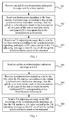
- FIG. 8 is a flow chart of Embodiment 7 of an uplink synchronization processing method according to the present invention. As shown in FIG. 8 , the method of this embodiment may include the following steps:
- Step 501 Send CC group information to a UE in a broadcasting manner or through dedicated signaling.
- the CC group information is used to instruct CCs in the same CC group to share a TA value.
- the CCs are grouped according to whether the CCs may share the same TA.
- the UE knows, according to the group information. whether the newly configured CCs belong to a certain CC group.
- Step 502 Send an uplink synchronization indication message to the UE.
- the uplink synchronization indication message may be a CC reconfiguration message or a PDCCH.
- the uplink synchronization indication message carries identification information of one or multiple newly configured CCs, so that when knowing, according to the identification information of the CCs, that the one or multiple newly configured CCs and a currently used CC do not belong to the same CC group, the UE executes uplink synchronization on the one or multiple newly configured CCs.
- the uplink synchronization indication message carries the identification information of the one or multiple newly configured CCs, and the identification information is used by the base station, for example, an eNodeB, to indicate to the UE which CC(s) is (are) newly configured.
- the CC reconfiguration message may further carry detailed configuration information of the newly configured CCs.
- the uplink synchronization indication message may be sent as an independent RRC message or an MAC PDU, or is sent by being carried in an RRC connection reconfiguration message.
- the UE executes uplink synchronization on the one or multiple newly configured CCs.
- the specific procedure of executing the uplink synchronization may adopt a random access procedure based on competition.
- the procedure of executing the uplink synchronization on the one or multiple newly configured CCs of this embodiment may adopt the uplink synchronization method described in any one of Embodiment 1 to Embodiment 5, and is not described again.
- a target base station may distributes multiple CCs for the UE to use after the handover in a handover command.
- the base station may notify the UE of the CC group information in the handover command.
- the UE may select, based on the group information of the multiple CCs obtained in the handover command, one CC from each CC group to execute the uplink synchronization.
- the base station may designate, in the handover command, one CC used to execute the uplink synchronization in each CC group for the UE.
- the UE may know, according to the CC group information and the newly configured identification information, whether the newly configured CCs belong to a certain CC group, and when the newly configured CCs belong to the certain CC group, the UE realizes the uplink synchronization by directly using the TA corresponding to the CC group, and when the newly configured CCs do not belong to the certain CC group, the UE initiates the uplink synchronization operation to the base station, to obtain the TA value used on the newly configured CCs from the base station.
- the UE when the base station needs to configure a new CC for the UE, or one or multiple CCs currently used by the UE need to be replaced by newly configured CCs, the UE may achieve the uplink synchronization with the newly configured CCs.
- FIG. 9 is a flow chart of Embodiment 8 of an uplink synchronization processing method according to the present invention. As shown in FIG. 9 , the method of this embodiment may include the following steps:
- Step 601 Receive an uplink synchronization indication message sent by a base station.
- the uplink synchronization indication message carries identification information of one or multiple newly configured CCs and indication information of sending a Sounding RS on the one or multiple newly configured CCs.
- the sounding reference signal may be the Sounding RS.
- a UE when communicating with the base station, a UE needs to send the Sounding RS to the base station, to ensure that the base station may detect signal quality of the UE on the entire uplink bandwidth in real time.
- the base station when reconfiguring the CC for the UE, the base station may instruct the UE to firstly send the Sounding RS on the newly configured CCs, and then the base station may determine the TA value based on detection of the Sounding RS.
- Step 602 Send the Sounding RS to the base station on the one or multiple newly configured CCs according to the indication information.
- Step 603 Receive a TA adjusting message that is sent by the base station according to the Sounding RS, and apply the TA value carried in the TA adjusting message to the CC corresponding to the identification information.
- the uplink synchronization indication message includes: a CC reconfiguration message, a PDCCH, or an MAC PDU
- the TA adjusting message includes: an extended TA value adjusting command, where the extended TA value adjusting command includes the TA value that is on the one newly configured CC and requires adjustment, or the extended TA value adjusting command includes the one or multiple TA values that are on the multiple newly configured CCs and require adjustment and identification information of the CC corresponding to each TA value.
- the extended TA adjusting command may adopt the extended TA adjusting command described in Embodiment 1 to Embodiment 5, and is not described again.
- the TA adjusting message is the CC reconfiguration message
- the CC reconfiguration message includes the TA value that is on the one newly configured CC and requires adjustment
- the CC reconfiguration message includes one or multiple TA values that are on the multiple newly configured CCs and requires adjustment and the identification information of the CC corresponding to each TA value.
- the base station sends the uplink synchronization indication message carrying the indication information enabling the UE to send the Sounding RS to the UE, so that after receiving the uplink synchronization indication message, the UE sends the Sounding RS to the base station, therefore, the base station obtains the TA value used on the CC newly configured for the UE through calculation according to the Sounding RS, and sends the TA value to the UE. Therefore, in this embodiment, when the base station needs to configure a new CC for the UE, or one or multiple CCs currently used by the UE need to be replaced by newly configured CCs, the UE may achieve the uplink synchronization with the newly configured CCs.
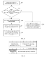
- FIG. 10 is a flow chart of Embodiment 9 of an uplink synchronization processing method according to the present invention. As shown in FIG. 10 , the method of this embodiment may include the following steps:
- Step 701 Send an uplink synchronization indication message to a UE.
- the uplink synchronization indication message carries identification information of one or multiple newly configured CCs and indication information of sending a Sounding RS on the one or multiple newly configured CCs.
- the sounding reference signal may be the Sounding RS.
- a UE when communicating with the base station, a UE needs to send the Sounding RS to the base station, to ensure that the base station may detect signal quality of the UE on the entire uplink bandwidth in real time.
- the base station when reconfiguring the CC for the UE, the base station may indicate the UE to firstly send the Sounding RS on the newly configured CCs, and then the base station may determine the TA value based on detection of the Sounding RS.
- Step 702 Receive the Sounding RS that is sent by the UE to the base station on the one or multiple newly configured CCs according to the indication information.
- Step 703 Send a TA adjusting message to the UE according to the Sounding RS, and apply the TA value carried in the TA adjusting message to the CC corresponding to the identification information.
- the uplink synchronization indication message includes: a CC reconfiguration message, a PDCCH, or an MAC PDU
- the TA adjusting message includes: an extended TA value adjusting command, where the extended TA value adjusting command includes the TA value that is on the one newly configured CC and requires adjustment, or the extended TA value adjusting command includes the one or multiple TA values that are on the multiple newly configured CCs and require adjustment and identification information of the CC corresponding to each TA value.
- the extended TA adjusting command may adopt the extended TA adjusting command described in Embodiment 1 to Embodiment 5, and is not described again.
- the TA adjusting message is the CC reconfiguration message
- the CC reconfiguration message includes the TA value that is on the one newly configured CC and requires adjustment
- the CC reconfiguration message includes one or multiple TA values that are on the multiple newly configured CCs and require adjustment and the identification information of the CC corresponding to each TA value.
- the base station sends the uplink synchronization indication message which carries the indication information enabling the UE to send the Sounding RS to the UE, so that after receiving the uplink synchronization indication message, the UE sends the Sounding RS to the base station, therefore, the base station obtains the TA values used on the CCs newly configured for the UE through calculation according to the Sounding RS, and sends the TA value to the UE. Therefore, in this embodiment, when the base station needs to configure a new CC for the UE, or one or multiple CCs currently used by the UE need to be replaced by newly configured CCs, the UE may achieve the uplink synchronization with the newly configured CCs.
- the UE executes the uplink synchronization.
- a group of preambles may be set in advance, the preambles in the group are dedicatedly used during CC reconfiguration; alternatively, in addition to an original random access channel, a new random access channel is dedicatedly set to send random access preambles during the CC reconfiguration, or during the CC reconfiguration, a PUSCH resource dedicatedly used to send the random access Preambles is dispatched for the UE, to prevent negative effects on the conventional random access procedure.
- the method of this embodiment may specifically include that: the base station sends the CC reconfiguration message to the UE; after receiving the CC reconfiguration message, the UE selects a preamble from the preamble group dedicatedly used during the CC reconfiguration and sends the preamble to the base station, or if the system does not have the preamble group dedicatedly used during the CC reconfiguration, but sets the new random access channel for the CC reconfiguration, the UE randomly selects one from currently available preambles, and sends the preamble to the base station on the new random access channel dedicatedly used during the CC reconfiguration, further, if the system does not set the dedicated preamble and the new random access channel for the CC reconfiguration, when sending the CC reconfiguration message to the UE, the base station may dispatch, in the CC reconfiguration message, the PUSCH resource used to send the preamble for the UE, and the UE randomly selects one from the currently available preambles, and then sends the selected preamble on the dispatches
- the TA adjusting command needs to include the TA value, besides, it further needs to include the identification information of the detected preamble sent by the UE (the identification information may be the identification information in the dedicated preamble group, or the identification information of all the preambles in a current cell), and optionally, the TA adjusting command may include the identification information of the newly configured CCs.
- the extended TA adjusting command may adopt the extended TA adjusting command described in Embodiment 1 to Embodiment 5.
- the UE when the base station needs to configure a new CC for the UE, or one or multiple CCs currently used by the UE need to be replaced by newly configured CCs, the UE may achieve the uplink synchronization with the newly configured CCs.
- FIG. 11 is a flow chart of Embodiment 10 of an uplink synchronization processing method according to the present invention. As shown in FIG. 11 , the method of this embodiment may include the following steps:
- the UE may adjust TA situation of the newly configured CC according to the TA value of the already configured CC, no matter whether multiple CCs share the TA, the UE may calculate the uplink TA of the newly configured CC according to the downlink TA and the uplink TA of the already configured CC and the downlink timing value of the newly configured CC. It should be understood that this embodiment may be combined with the methods of other embodiments, to calculate the TA value of the newly configured CCs. In this embodiment, when the base station needs to configure a new CC for the UE, or one or multiple CCs currently used by the UE need to be replaced by newly configured CCs, the UE may achieve the uplink synchronization with the newly configured CCs.
- the TA adjustment during the CC reconfiguration is described by taking frequency division duplex as an example, and for time division duplex, because as for a CC, there is no differentiation between an uplink CC and a downlink CC, so that when the CC reconfiguration in any embodiment is directly replaced by the CC reconfiguration under the time division duplex, the methods in all the embodiments are available.
- the method in the following may be used to replace the using of the dedicated preamble, and a specific procedure is as follows.
- the UE When knowing that the uplink synchronization needs to be executed on the one or multiple newly configured CCs, the UE randomly selects one or multiple preambles, and sends the preamble to the base station on the one or multiple CCs on which the uplink synchronization needs to be executed.
- the UE reports the identification information of the selected preambles to the base station on the currently used CC, where the UE may report the index of the selected preamble to the base station by using any one of the manners in the following:
- the base station may send the TA value to the UE by using the random access response message based on the TA value obtained through the detection of the preamble.
- the UE needs to indicate multiple TA values in the random access response message, and needs to indicate the identification information of the CCs corresponding to the multiple TA values, that is, the UE is enabled to explicitly know the corresponding relationship between the TA value and the CC.
- the one or multiple TA values detected by the base station may be sent to the UE by using the extended TA command message or the CC reconfiguration message in each embodiment.
- the UE may initiate the uplink synchronization on the uplink CC, that is, may execute the random access procedure on the uplink CC, or may execute the uplink synchronization operation according to the methods of other embodiments of the present invention.
- FIG. 12 is a schematic structural diagram of Embodiment 1 of a UE according to the present invention.
- the UE of this embodiment may include: a first receiving module 11, a first sending module 12, and a first processing module 13, where the first receiving module 11 is configured to receive an uplink synchronization indication message sent by a base station, the uplink synchronization indication message carries identification information of one or multiple newly configured CCs; the first sending module 12 is configured to send synchronization signaling to the base station when knowing that the uplink synchronization needs to be executed on all or a part of the one or multiple newly configured CCs corresponding to the identification information; and the first processing module 13 is configured to apply a TA value carried in a TA adjusting message to the CC on which the uplink synchronization needs to be executed, after the first receiving module receives the TA adjusting message that is sent by the base station according to the synchronization signaling.
- a realizing principle of the UE of this embodiment is the same as that of Embodiment 1 of the uplink synchronization processing method as shown in FIG. 1 , and is not described again.
- the first receiving module is further configured to receive an extended TA value adjusting command that is sent by the base station according to the synchronization signaling, and the extended TA value adjusting command includes a TA value that is on the one newly configured CC and requires adjustment, or the extended TA value adjusting command includes one or multiple TA values that are on the multiple newly configured CCs and require adjustment, and the identification information of the CC corresponding to each TA value.
- a realizing principle of the UE of this embodiment is the same as that of Embodiment 3 of the uplink synchronization processing method as shown in FIG. 3 , and is not described again.
- the first receiving module is further configured to receive an extended TA value adjusting command that is sent by the base station according to the synchronization signaling, and receive a CC reconfiguration message sent by the base station.
- a realizing principle of the UE of this embodiment is the same as that of Embodiment 4 of the uplink synchronization processing method as shown in FIG. 5 , and is not described again.
- the first receiving module is further configured to receive a CC reconfiguration message that is sent by the base station according to the synchronization signaling, where the CC reconfiguration message includes a TA value that is on the one newly configured CC and requires adjustment, or the CC reconfiguration message includes one or multiple TA values that are on the multiple newly configured CCs and require adjustment, and the identification information of the CC corresponding to each TA value.
- a realizing principle of the UE of this embodiment is the same as that of Embodiment 5 of the uplink synchronization processing method as shown in FIG. 6 , and is not described again.
- the first processing module when knowing, according to the uplink synchronization indication message, that the uplink synchronization does not need to be executed on all or a part of the one or multiple newly configured CCs corresponding to the identification information, the first processing module is further configured to apply an indicated TA value in the uplink synchronization indication message to the newly configured CC on which the uplink synchronization does not need to be executed.
- the UE may achieve the uplink synchronization with the newly configured CCs by using the obtained TA value.
- the UE is triggered to execute the uplink synchronization only through the uplink synchronization indication message, for example, the CC reconfiguration message or the PDCCH, to save downlink radio resources, and when the UE needs to execute the uplink synchronization, the UE may send synchronization signaling to the base station, for example, a dedicated preamble, to obtain TA values required to be used on the newly configured CCs from the base station, thereby improving an uplink synchronization speed.
- the base station for example, a dedicated preamble
- the UE may directly apply the TA value indicated in the uplink synchronization indication message to the newly configured CC on which the uplink synchronization does not need to be executed, or the UE may directly apply the unique TA value on the currently used CC to the newly configured CC on which the uplink synchronization does not need to be executed, so that the UE may achieve the uplink synchronization with the newly configured CCs when it does not need to execute the uplink synchronization.
- FIG. 13 is a schematic structural diagram of Embodiment 1 of a base station according to the present invention.
- the base station of this embodiment may include: a second sending module 21 and a second receiving module 22, where the second sending module 21 is configured to send an uplink synchronization indication message to a UE, and the uplink synchronization indication message carries identification information of one or multiple newly configured CCs and the second receiving module 22 is configured to receive synchronization signaling sent by the UE, where the second sending module 21 is further configured to send a TA adjusting message to the UE according to the synchronization signaling, to instruct the UE to apply a TA value carried in the TA adjusting message to the CC on which the uplink synchronization needs to be executed.
- a realizing principle of the base station of this embodiment is the same as that of Embodiment 1 of the uplink synchronization processing method as shown in FIG. 2 , and is not described again.
- the second sending module is further configured to send an extended TA value adjusting command to the UE, and the extended TA value adjusting command includes a TA value that is on the one newly configured CC and requires adjustment, or the extended TA value adjusting command includes one or multiple TA values that are on the multiple newly configured CCs and requires adjustment, and the identification information of the CC corresponding to each TA value.
- a realizing principle of the base station of this embodiment is the same as that of Embodiment 3 of the uplink synchronization processing method as shown in FIG. 3 , and is not described again.
- the second sending module is further configured to send an extended TA value adjusting command and a CC reconfiguration message to the UE.
- a realizing principle of the base station of this embodiment is the same as that of Embodiment 4 of the uplink synchronization processing method as shown in FIG. 5 , and is not described again.
- the second sending module is further configured to send an extend TA value adjusting command and a CC reconfiguration message to the UE; or the second sending module is further configured to send a CC reconfiguration message to the UE, where the CC reconfiguration message includes a TA value of the UE, which is on the one newly configured CC and require adjustment, or the CC reconfiguration message includes one or multiple TA values of the UE, which are on the multiple newly configured CCs and require adjustment, and the identification information of the CC corresponding to each TA value.
- a realizing principle of the base station of this embodiment is the same as that of Embodiment 5 of the uplink synchronization processing method as shown in FIG. 6 , and is not described again.
- the base station may send the uplink synchronization indication message to the UE, so that when the base station needs to configure a new CC for the UE, or one or multiple CCs currently used by the UE need to be replaced by newly configured CCs, whether the uplink synchronization is required to be executed may be known according to the uplink synchronization indication message, so that the UE may achieve the uplink synchronization with the newly configured CCs.
- the UE is triggered to execute the uplink synchronization only through the uplink synchronization indication message, to save downlink radio resources, and when the UE needs to execute the uplink synchronization, the UE may send synchronization signaling to the base station, for example, a dedicated preamble, to obtain TA values required to be used on the newly configured CCs from the base station, thereby improving an uplink synchronization speed.
- the base station for example, a dedicated preamble
- the UE may directly apply the TA value indicated in the uplink synchronization indication message to the newly configured CC on which the uplink synchronization does not need to be executed, or the UE may directly apply the unique TA value on the currently used CC to the newly configured CC on which the uplink synchronization does not need to be executed, so that the UE may achieve the uplink synchronization with the newly configured CCs when it does not need to execute the uplink synchronization.
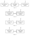
- FIG. 14 is a schematic structural diagram of Embodiment 2 of a UE according to the present invention.
- the UE of this embodiment may include: a third receiving module 31 and a third processing module 32, where the third receiving module 31 is configured to receive an uplink synchronization indication message sent by a base station, the uplink synchronization indication message carries identification information of one or multiple newly configured CCs; and the third processing module 32 is configured to execute uplink synchronization on the one or multiple newly configured CCs when knowing, according to the identification information of the CCs, that the one or multiple newly configured CCs and a currently used CC do not belong to the same CC group, where the CC group is formed by one or multiple CCs sharing the same TA value.
- the third receiving module 31 is further configured to receive CC group information sent by the base station in a broadcasting manner or through dedicated signaling, where the CC group information is used to instruct CCs in the same CC group to share a TA value.
- a realizing principle of the base station of this embodiment is the same as that of Embodiment 6 of the uplink synchronization processing method as shown in FIG. 7 , and is not described again.
- the UE may know, according to the CC group information and the newly configured identification information, whether the newly configured CCs belong to a certain CC group, and when the newly configured CCs belong to the certain CC group, the UE realizes the uplink synchronization by directly using the TA corresponding to the CC group, and when the newly configured CCs do not belong to the certain CC group, the UE initiates the uplink synchronization operation to the base station, to obtain the TA value used on the newly configured CCs from the base station. Therefore, when the base station needs to configure a new CC for the UE, or one or multiple CCs currently used by the UE need to be replaced by newly configured CCs, the UE may achieve the uplink synchronization with the newly configured CCs.
- FIG. 15 is a schematic structural diagram of Embodiment 2 of a base station according to the present invention.
- the base station of this embodiment may include: a third sending module 41 and a fourth sending module 42, where the third sending module 41 is configured to send CC group information to a UE in a broadcasting manner or through dedicated signaling, and the CC group information is used to instruct CCs in the same CC group to share a TA value; and the fourth sending module 42 is configured to send an uplink synchronization indication message to the UE, and the uplink synchronization indication message carries identification information of one or multiple newly configured CCs, so that when knowing, according to the identification information of the CCs, that the one or multiple newly configured CCs and a currently used CC do not belong to the same CC group, the UE executes uplink synchronization on the one or multiple newly configured CCs.
- a realizing principle of the base station of this embodiment is the same as that of Embodiment 7 of the uplink synchronization processing method as shown in FIG. 8 , and is not described again.
- the UE may know, according to the CC group information and the newly configured identification information, whether the newly configured CCs belong to the certain CC group, when the newly configured CCs belong to the certain CC group, the UE realizes the uplink synchronization by directly using the TA corresponding to the CC group, and when the newly configured CCs do not belong to the certain CC group, the UE initiates the uplink synchronization operation to the base station, to obtain the TA value used on the newly configured CCs from the base station.
- the UE may achieve the uplink synchronization with the newly configured CCs.
Landscapes
- Engineering & Computer Science (AREA)
- Computer Networks & Wireless Communication (AREA)
- Signal Processing (AREA)
- Mobile Radio Communication Systems (AREA)
Priority Applications (2)
| Application Number | Priority Date | Filing Date | Title |
|---|---|---|---|
| EP13170077.5A EP2635078B1 (de) | 2009-09-15 | 2009-09-15 | Uplink-Synchronisationsverarbeitungsverfahren, Benutzergerät und Basisstation |
| EP18196225.9A EP3439383B1 (de) | 2009-09-15 | 2009-09-15 | Uplink-synchronisationsverarbeitungsverfahren, benutzergerät und basisstation |
Applications Claiming Priority (1)
| Application Number | Priority Date | Filing Date | Title |
|---|---|---|---|
| PCT/CN2009/073943 WO2011032308A1 (zh) | 2009-09-15 | 2009-09-15 | 上行同步处理方法、用户设备和基站 |
Related Child Applications (3)
| Application Number | Title | Priority Date | Filing Date |
|---|---|---|---|
| EP13170077.5A Division-Into EP2635078B1 (de) | 2009-09-15 | 2009-09-15 | Uplink-Synchronisationsverarbeitungsverfahren, Benutzergerät und Basisstation |
| EP13170077.5A Division EP2635078B1 (de) | 2009-09-15 | 2009-09-15 | Uplink-Synchronisationsverarbeitungsverfahren, Benutzergerät und Basisstation |
| EP18196225.9A Division EP3439383B1 (de) | 2009-09-15 | 2009-09-15 | Uplink-synchronisationsverarbeitungsverfahren, benutzergerät und basisstation |
Publications (3)
| Publication Number | Publication Date |
|---|---|
| EP2472965A1 true EP2472965A1 (de) | 2012-07-04 |
| EP2472965A4 EP2472965A4 (de) | 2012-10-31 |
| EP2472965B1 EP2472965B1 (de) | 2016-11-09 |
Family
ID=43758011
Family Applications (3)
| Application Number | Title | Priority Date | Filing Date |
|---|---|---|---|
| EP18196225.9A Active EP3439383B1 (de) | 2009-09-15 | 2009-09-15 | Uplink-synchronisationsverarbeitungsverfahren, benutzergerät und basisstation |
| EP09849362.0A Active EP2472965B1 (de) | 2009-09-15 | 2009-09-15 | Uplink-synchronisationsverarbeitungsverfahren, benutzergerät und basisstation |
| EP13170077.5A Active EP2635078B1 (de) | 2009-09-15 | 2009-09-15 | Uplink-Synchronisationsverarbeitungsverfahren, Benutzergerät und Basisstation |
Family Applications Before (1)
| Application Number | Title | Priority Date | Filing Date |
|---|---|---|---|
| EP18196225.9A Active EP3439383B1 (de) | 2009-09-15 | 2009-09-15 | Uplink-synchronisationsverarbeitungsverfahren, benutzergerät und basisstation |
Family Applications After (1)
| Application Number | Title | Priority Date | Filing Date |
|---|---|---|---|
| EP13170077.5A Active EP2635078B1 (de) | 2009-09-15 | 2009-09-15 | Uplink-Synchronisationsverarbeitungsverfahren, Benutzergerät und Basisstation |
Country Status (7)
| Country | Link |
|---|---|
| US (5) | US8724617B2 (de) |
| EP (3) | EP3439383B1 (de) |
| CN (1) | CN102239735B (de) |
| ES (2) | ES2797425T3 (de) |
| HU (1) | HUE031543T2 (de) |
| PL (1) | PL2472965T3 (de) |
| WO (1) | WO2011032308A1 (de) |
Cited By (3)
| Publication number | Priority date | Publication date | Assignee | Title |
|---|---|---|---|---|
| US20140044074A1 (en) * | 2011-03-31 | 2014-02-13 | China Academy Of Telecommunications Technology | Random access method and apparatus based on multiple uplink timing advances |
| EP2695472A4 (de) * | 2011-04-02 | 2014-09-10 | Alcatel Lucent | Direktzugriffsverfahren |
| US8983517B2 (en) | 2010-01-12 | 2015-03-17 | Huawei Technologies Co., Ltd. | Method, device, and system for determining timing advance grouping |
Families Citing this family (46)
| Publication number | Priority date | Publication date | Assignee | Title |
|---|---|---|---|---|
| US9137764B2 (en) * | 2009-03-17 | 2015-09-15 | Htc Corporation | Method of managing timing alignment functionality for multiple component carriers and related communication device |
| HUE031543T2 (en) | 2009-09-15 | 2017-07-28 | Huawei Tech Co Ltd | Upload Direction Sync Processing Process, User Device, and Base Station |
| WO2011085200A1 (en) | 2010-01-08 | 2011-07-14 | Interdigital Patent Holdings, Inc. | Maintaining time alignment with multiple uplink carriers |
| EP2676475B1 (de) | 2011-02-15 | 2022-04-06 | Samsung Electronics Co., Ltd. | Leistungsreservebericht |
| KR102073027B1 (ko) | 2011-04-05 | 2020-02-04 | 삼성전자 주식회사 | 반송파 집적 기술을 사용하는 무선통신시스템에서 복수 개의 타임 정렬 타이머 운용 방법 및 장치 |
| KR101885351B1 (ko) | 2011-02-21 | 2018-08-29 | 삼성전자 주식회사 | 단말 송신 전력량을 효율적으로 보고하는 방법 및 장치 |
| KR101995293B1 (ko) * | 2011-02-21 | 2019-07-02 | 삼성전자 주식회사 | 반송파 집적 기술을 사용하는 시분할 무선통신시스템에서 부차반송파의 활성화 또는 비활성화 방법 및 장치 |
| WO2012153993A2 (ko) | 2011-05-10 | 2012-11-15 | 삼성전자 주식회사 | 반송파 집적 기술을 사용하는 무선통신시스템에서 타임 정렬 타이머를 적용하는 방법 및 장치 |
| JP5724632B2 (ja) * | 2011-05-25 | 2015-05-27 | 富士通株式会社 | 基地局、及び通信方法 |
| US8395985B2 (en) | 2011-07-25 | 2013-03-12 | Ofinno Technologies, Llc | Time alignment in multicarrier OFDM network |
| EP2800431A4 (de) * | 2011-12-31 | 2015-12-16 | Fujitsu Ltd | Verfahren und vorrichtung zur vermeidung einer aufwärtsinterferenz nach der rekonfiguration einer zeitvorverschiebungsgruppe |
| EP3937551A3 (de) | 2012-01-25 | 2022-02-09 | Comcast Cable Communications, LLC | Direktzugriffskanal in einer drahtlosen mehrträgerkommunikation mit zeitvorlaufsgruppen |
| US9237537B2 (en) | 2012-01-25 | 2016-01-12 | Ofinno Technologies, Llc | Random access process in a multicarrier base station and wireless device |
| US8964780B2 (en) | 2012-01-25 | 2015-02-24 | Ofinno Technologies, Llc | Sounding in multicarrier wireless communications |
| US11943813B2 (en) | 2012-04-01 | 2024-03-26 | Comcast Cable Communications, Llc | Cell grouping for wireless communications |
| EP2835023B1 (de) | 2012-04-01 | 2021-09-01 | Comcast Cable Communications, LLC | Zellgruppekonfigurierung in einer drahtlosen vorrichtung und basisstation mit taktbeschleunigungsgruppen |
| US20130258956A1 (en) | 2012-04-01 | 2013-10-03 | Esmael Hejazi Dinan | Random Access Process in a Wireless Device |
| US8964593B2 (en) | 2012-04-16 | 2015-02-24 | Ofinno Technologies, Llc | Wireless device transmission power |
| US8971280B2 (en) | 2012-04-20 | 2015-03-03 | Ofinno Technologies, Llc | Uplink transmissions in a wireless device |
| US11582704B2 (en) | 2012-04-16 | 2023-02-14 | Comcast Cable Communications, Llc | Signal transmission power adjustment in a wireless device |
| US11825419B2 (en) | 2012-04-16 | 2023-11-21 | Comcast Cable Communications, Llc | Cell timing in a wireless device and base station |
| EP2839705B1 (de) | 2012-04-16 | 2017-09-06 | Comcast Cable Communications, LLC | Zellgruppenkonfiguration für uplink-übertragung in einer drahtlosen mehrträgervorrichtung und basisstation mit zeitvorlaufsgruppen |
| US11252679B2 (en) | 2012-04-16 | 2022-02-15 | Comcast Cable Communications, Llc | Signal transmission power adjustment in a wireless device |
| US8958342B2 (en) | 2012-04-17 | 2015-02-17 | Ofinno Technologies, Llc | Uplink transmission power in a multicarrier wireless device |
| US9179425B2 (en) | 2012-04-17 | 2015-11-03 | Ofinno Technologies, Llc | Transmit power control in multicarrier communications |
| US8971298B2 (en) | 2012-06-18 | 2015-03-03 | Ofinno Technologies, Llc | Wireless device connection to an application server |
| US11882560B2 (en) | 2012-06-18 | 2024-01-23 | Comcast Cable Communications, Llc | Carrier grouping in multicarrier wireless networks |
| US9179457B2 (en) | 2012-06-20 | 2015-11-03 | Ofinno Technologies, Llc | Carrier configuration in wireless networks |
| US9084228B2 (en) | 2012-06-20 | 2015-07-14 | Ofinno Technologies, Llc | Automobile communication device |
| US11622372B2 (en) | 2012-06-18 | 2023-04-04 | Comcast Cable Communications, Llc | Communication device |
| US9113387B2 (en) | 2012-06-20 | 2015-08-18 | Ofinno Technologies, Llc | Handover signalling in wireless networks |
| US9107206B2 (en) | 2012-06-18 | 2015-08-11 | Ofinne Technologies, LLC | Carrier grouping in multicarrier wireless networks |
| US9210619B2 (en) | 2012-06-20 | 2015-12-08 | Ofinno Technologies, Llc | Signalling mechanisms for wireless device handover |
| US9661612B2 (en) * | 2012-06-29 | 2017-05-23 | Samsung Electronics Co., Ltd. | Methods and apparatus for uplink control channel multiplexing in beamformed cellular systems |
| CN104756562B (zh) * | 2012-11-01 | 2019-06-14 | 索尼公司 | 通信控制装置、程序、通信控制方法和终端装置 |
| JP6259578B2 (ja) * | 2013-03-25 | 2018-01-10 | 株式会社Nttドコモ | 移動通信方法 |
| KR101783277B1 (ko) * | 2013-07-01 | 2017-09-29 | 후아웨이 테크놀러지 컴퍼니 리미티드 | 무선 인터페이스 기반 동기화 방법, 기지국, 제어 장치, 및 무선 통신 시스템 |
| US20150110076A1 (en) * | 2013-10-22 | 2015-04-23 | Qualcomm Incorporated | Reducing latency during redirection |
| CN108289334B (zh) * | 2017-01-10 | 2020-11-27 | 华为技术有限公司 | 一种信息接收、发送方法及设备 |
| CN108882260A (zh) * | 2017-05-08 | 2018-11-23 | 索尼公司 | 无线通信系统中的电子设备和方法 |
| CN109168170B (zh) * | 2017-06-29 | 2022-07-01 | 中国移动通信集团陕西有限公司 | 云无线接入网络调度方法及相关设备、介质 |
| CN109729578A (zh) * | 2017-10-27 | 2019-05-07 | 成都鼎桥通信技术有限公司 | 非对称上行载波聚合的上行同步方法及设备 |
| US10623067B2 (en) | 2018-05-11 | 2020-04-14 | At&T Intellectual Property I, L.P. | Enhanced timing advance scheme to support MU-MIMO in integrated access and backhaul |
| CN112655252B (zh) * | 2018-10-10 | 2023-07-11 | Oppo广东移动通信有限公司 | 同步指示方法、终端设备、网络设备、芯片及存储介质 |
| WO2020079763A1 (ja) * | 2018-10-16 | 2020-04-23 | 株式会社Nttドコモ | 端末及び通信方法 |
| MX2022003476A (es) * | 2019-10-04 | 2022-04-25 | Ericsson Telefon Ab L M | Acceso aleatorio para nodos de acceso y retroceso integrado. |
Family Cites Families (42)
| Publication number | Priority date | Publication date | Assignee | Title |
|---|---|---|---|---|
| US5802044A (en) | 1996-04-26 | 1998-09-01 | Motorola, Inc. | Multicarrier reverse link timing synchronization system, device and method |
| CN1189946A (zh) | 1996-04-26 | 1998-08-05 | 摩托罗拉公司 | 多载波反向链路定时同步系统、设备和方法 |
| US6788963B2 (en) | 2002-08-08 | 2004-09-07 | Flarion Technologies, Inc. | Methods and apparatus for operating mobile nodes in multiple a states |
| WO2005088853A1 (en) | 2004-03-09 | 2005-09-22 | Neocific Inc. | Methods and apparatus for random access in multi-carrier communication systems |
| US7578966B2 (en) | 2005-06-30 | 2009-08-25 | Intel Corporation | Solders with intermetallic phases, solder bumps made thereof, packages containing same, and methods of assembling packages therewith |
| CN101438511A (zh) * | 2006-03-24 | 2009-05-20 | 交互数字技术公司 | 用于保持上行链路同步并且降低电池功耗的方法和设备 |
| CA2651229C (en) * | 2006-05-01 | 2013-03-19 | Nokia Corporation | Apparatus, method and computer program product providing uplink synchronization through use of dedicated uplink resource assignment |
| JP4603075B2 (ja) | 2006-06-19 | 2010-12-22 | 株式会社エヌ・ティ・ティ・ドコモ | 基地局、移動局、同期制御方法及びicチップ |
| US8051598B2 (en) | 2006-07-18 | 2011-11-08 | Expedite International | Universal decoy system |
| US7809673B2 (en) | 2006-11-21 | 2010-10-05 | Lockheed Martin Corporation | Methods and apparatus for interfacing external systems with vehicle electronic systems |
| GB2458418B (en) * | 2006-12-19 | 2011-08-03 | Lg Electronics Inc | Sequence generating method for efficient detection and method for transmitting and receiving signals using the same |
| JP4533915B2 (ja) | 2007-02-07 | 2010-09-01 | 株式会社エヌ・ティ・ティ・ドコモ | 移動局、無線アクセスネットワーク装置及び移動通信システム |
| JP4812670B2 (ja) | 2007-03-23 | 2011-11-09 | 株式会社エヌ・ティ・ティ・ドコモ | 送信再開方法及び無線基地局 |
| EP2139259B1 (de) | 2007-03-23 | 2012-04-25 | NTT DoCoMo, Inc. | Übertragungsneustartverfahren, mobilstation und drahtlose basisstation |
| JP5140300B2 (ja) | 2007-03-23 | 2013-02-06 | 株式会社エヌ・ティ・ティ・ドコモ | 移動局、無線基地局及び同期確立方法 |
| CN101277145B (zh) | 2007-03-30 | 2012-05-09 | 联想(北京)有限公司 | 一种主、副子载波的切换方法 |
| CN101682889B (zh) * | 2007-04-24 | 2013-11-06 | 株式会社Ntt都科摩 | 移动通信方法、无线基站、移动台以及处理器 |
| WO2008133310A1 (ja) * | 2007-04-24 | 2008-11-06 | Ntt Docomo, Inc. | 移動通信方法及び無線基地局 |
| US8391192B2 (en) | 2007-05-14 | 2013-03-05 | Qualcomm Incorporated | Carrier switching in a multi-carrier wireless communication network |
| ES2439955T3 (es) * | 2007-06-12 | 2014-01-27 | Sharp Kabushiki Kaisha | Utilización de una zona en la que normalmente es enviada información de asignación de recursos radioeléctricos, para ordenar una señal de acceso aleatorio - dispositivo de estación base, dispositivo de estación móvil y métodos correspondientes |
| US8411664B2 (en) * | 2007-11-05 | 2013-04-02 | Telefonaktiebolaget Lm Ericsson (Publ) | Random access preamble collision detection |
| US8515425B2 (en) | 2007-12-19 | 2013-08-20 | Alcatel Lucent | Uplink carrier handoff and method for path loss based triggering of uplink carrier handoff |
| US20100074201A1 (en) * | 2008-09-22 | 2010-03-25 | Chih-Hsiang Wu | Method for improving uplink signaling transmission for a wireless communications system and related communication device |
| US8750218B2 (en) | 2008-09-29 | 2014-06-10 | Blackberry Limited | Message processing in communication systems |
| KR101227740B1 (ko) * | 2008-10-01 | 2013-01-29 | 엘지전자 주식회사 | 서브프레임의 무선자원 할당 방법 및 장치 |
| US8514793B2 (en) * | 2008-10-31 | 2013-08-20 | Interdigital Patent Holdings, Inc. | Method and apparatus for monitoring and processing component carriers |
| CN101388722B (zh) | 2008-11-03 | 2013-06-26 | 新邮通信设备有限公司 | 一种上行同步控制方法、基站和用户设备 |
| CN101409700B (zh) | 2008-11-27 | 2015-03-04 | 北京邮电大学 | 一种多载波通信系统同步方法及设备 |
| US9247532B2 (en) * | 2009-01-02 | 2016-01-26 | Lg Electronics Inc. | Effective method for transmitting control information during the combination of multiple carriers for wideband support |
| KR101356525B1 (ko) * | 2009-03-13 | 2014-01-29 | 엘지전자 주식회사 | 상하향링크 콤포넌트 반송파 설정을 고려한 핸드오버 |
| US9137764B2 (en) * | 2009-03-17 | 2015-09-15 | Htc Corporation | Method of managing timing alignment functionality for multiple component carriers and related communication device |
| US8989105B2 (en) | 2009-03-17 | 2015-03-24 | Htc Corporation | Method of establishing multiple links with multiple component carriers and related communication device |
| CN102388545B (zh) * | 2009-04-09 | 2014-12-10 | Lg电子株式会社 | 在中继通信系统中的信号发送方法和装置 |
| ES2905362T3 (es) * | 2009-04-23 | 2022-04-08 | Interdigital Patent Holdings Inc | Método y aparato para acceso aleatorio en comunicaciones inalámbricas multiportadoras |
| CN101932052B (zh) | 2009-06-23 | 2016-08-24 | 华为技术有限公司 | 一种切换方法、用户终端及网络侧设备 |
| CN101938344A (zh) * | 2009-06-29 | 2011-01-05 | 宏达国际电子股份有限公司 | 处理传输以及传输状态信息的方法及其相关通讯装置 |
| US8755298B2 (en) * | 2009-07-06 | 2014-06-17 | Lg Electronics Inc. | Method and apparatus for random access in a wireless communication system |
| US8830969B2 (en) * | 2009-07-15 | 2014-09-09 | Lg Electronics Inc. | Carrier reconfiguration in multi-carrier aggregation |
| JP2011030197A (ja) | 2009-07-23 | 2011-02-10 | Innovative Sonic Corp | スケジューリングリクエストの方法及び通信装置 |
| CN101646234A (zh) * | 2009-09-01 | 2010-02-10 | 中兴通讯股份有限公司 | 一种定时提前量的获取方法 |
| US9351293B2 (en) * | 2009-09-11 | 2016-05-24 | Qualcomm Incorporated | Multiple carrier indication and downlink control information interaction |
| HUE031543T2 (en) * | 2009-09-15 | 2017-07-28 | Huawei Tech Co Ltd | Upload Direction Sync Processing Process, User Device, and Base Station |
-
2009
- 2009-09-15 HU HUE09849362A patent/HUE031543T2/en unknown
- 2009-09-15 EP EP18196225.9A patent/EP3439383B1/de active Active
- 2009-09-15 ES ES18196225T patent/ES2797425T3/es active Active
- 2009-09-15 CN CN200980147162.5A patent/CN102239735B/zh active Active
- 2009-09-15 EP EP09849362.0A patent/EP2472965B1/de active Active
- 2009-09-15 ES ES09849362.0T patent/ES2612867T3/es active Active
- 2009-09-15 WO PCT/CN2009/073943 patent/WO2011032308A1/zh not_active Ceased
- 2009-09-15 EP EP13170077.5A patent/EP2635078B1/de active Active
- 2009-09-15 PL PL09849362T patent/PL2472965T3/pl unknown
-
2012
- 2012-03-15 US US13/421,665 patent/US8724617B2/en active Active
-
2013
- 2013-12-26 US US14/140,902 patent/US9131435B2/en active Active
-
2014
- 2014-04-14 US US14/252,365 patent/US9220077B2/en active Active
-
2015
- 2015-08-11 US US14/823,278 patent/US9743366B2/en active Active
-
2017
- 2017-07-28 US US15/663,391 patent/US10536912B2/en active Active
Non-Patent Citations (6)
| Title |
|---|
| "3rd Generation Partnership Project; Technical Specification Group Radio Access Network; Evolved Universal Terrestrial Radio Access (E-UTRA) Medium Access Control (MAC) protocol specification (Release 8)", 3GPP STANDARD; 3GPP TS 36.321, 3RD GENERATION PARTNERSHIP PROJECT (3GPP), MOBILE COMPETENCE CENTRE ; 650, ROUTE DES LUCIOLES ; F-06921 SOPHIA-ANTIPOLIS CEDEX ; FRANCE, no. V8.7.0, 1 September 2009 (2009-09-01), pages 1-44, XP050377623, * |
| ALCATEL-LUCENT: "[Draft] LS Reply to RAN2 on Carrier Aggregation", 3GPP DRAFT; R1-093335, 3RD GENERATION PARTNERSHIP PROJECT (3GPP), MOBILE COMPETENCE CENTRE ; 650, ROUTE DES LUCIOLES ; F-06921 SOPHIA-ANTIPOLIS CEDEX ; FRANCE, no. Shenzhen, China; 20090824, 24 August 2009 (2009-08-24), XP050388117, [retrieved on 2009-08-29] * |
| HUAWEI: "Issues in carrier aggregation", 3GPP DRAFT; R1-092377, 3RD GENERATION PARTNERSHIP PROJECT (3GPP), MOBILE COMPETENCE CENTRE ; 650, ROUTE DES LUCIOLES ; F-06921 SOPHIA-ANTIPOLIS CEDEX ; FRANCE, no. Los Angeles, USA; 20090624, 24 June 2009 (2009-06-24), XP050350895, [retrieved on 2009-06-24] * |
| LG ELECTRONICS INC: "Text Proposal to TS 36.321 on Max No of TX for RACH MSG 3", 3GPP DRAFT; R2-082762 TEXT PROPOSAL ON THE MAX NUMBER OF TX FOR RACH MSG3, 3RD GENERATION PARTNERSHIP PROJECT (3GPP), MOBILE COMPETENCE CENTRE ; 650, ROUTE DES LUCIOLES ; F-06921 SOPHIA-ANTIPOLIS CEDEX ; FRANCE, vol. RAN WG2, no. Kansas City, USA; 20080514, 14 May 2008 (2008-05-14), XP050140352, [retrieved on 2008-05-14] * |
| See also references of WO2011032308A1 * |
| TEXAS INSTRUMENTS: "On RACH Procedure for Asymmetric Carrier Aggregation", 3GPP DRAFT; R1-091298 TI RACH CARRIER AGGREGATION, 3RD GENERATION PARTNERSHIP PROJECT (3GPP), MOBILE COMPETENCE CENTRE ; 650, ROUTE DES LUCIOLES ; F-06921 SOPHIA-ANTIPOLIS CEDEX ; FRANCE, no. Seoul, Korea; 20090318, 18 March 2009 (2009-03-18), XP050338905, [retrieved on 2009-03-18] * |
Cited By (7)
| Publication number | Priority date | Publication date | Assignee | Title |
|---|---|---|---|---|
| US8983517B2 (en) | 2010-01-12 | 2015-03-17 | Huawei Technologies Co., Ltd. | Method, device, and system for determining timing advance grouping |
| EP2525612B1 (de) * | 2010-01-12 | 2016-10-19 | Huawei Technologies Co., Ltd. | Verfahren, vorrichtung und system zur festlegung von zeitvorlaufsgruppen |
| US10085287B2 (en) | 2010-01-12 | 2018-09-25 | Huawei Technologies Co., Ltd | Method, device, and system for determining timing advance grouping |
| US10645732B2 (en) | 2010-01-12 | 2020-05-05 | Huawei Technologies Co., Ltd. | Method, device, and system for determining timing advance grouping |
| US20140044074A1 (en) * | 2011-03-31 | 2014-02-13 | China Academy Of Telecommunications Technology | Random access method and apparatus based on multiple uplink timing advances |
| US9883534B2 (en) * | 2011-03-31 | 2018-01-30 | China Academy Of Telecommunications Technology | Random access method and apparatus based on multiple uplink timing advances |
| EP2695472A4 (de) * | 2011-04-02 | 2014-09-10 | Alcatel Lucent | Direktzugriffsverfahren |
Also Published As
| Publication number | Publication date |
|---|---|
| ES2797425T3 (es) | 2020-12-02 |
| US9743366B2 (en) | 2017-08-22 |
| EP2472965A4 (de) | 2012-10-31 |
| US10536912B2 (en) | 2020-01-14 |
| EP2635078A1 (de) | 2013-09-04 |
| US9131435B2 (en) | 2015-09-08 |
| EP2472965B1 (de) | 2016-11-09 |
| ES2612867T3 (es) | 2017-05-19 |
| EP3439383B1 (de) | 2020-04-15 |
| CN102239735B (zh) | 2014-06-04 |
| US9220077B2 (en) | 2015-12-22 |
| HUE031543T2 (en) | 2017-07-28 |
| US20150351062A1 (en) | 2015-12-03 |
| EP3439383A1 (de) | 2019-02-06 |
| US20140219271A1 (en) | 2014-08-07 |
| US20140105169A1 (en) | 2014-04-17 |
| PL2472965T3 (pl) | 2017-06-30 |
| EP2635078B1 (de) | 2018-11-07 |
| WO2011032308A1 (zh) | 2011-03-24 |
| US8724617B2 (en) | 2014-05-13 |
| CN102239735A (zh) | 2011-11-09 |
| US20120170570A1 (en) | 2012-07-05 |
| US20170332337A1 (en) | 2017-11-16 |
Similar Documents
| Publication | Publication Date | Title |
|---|---|---|
| EP2635078B1 (de) | Uplink-Synchronisationsverarbeitungsverfahren, Benutzergerät und Basisstation | |
| US10959217B2 (en) | Method and apparatus for transmitting and receiving data using plurality of carriers in wireless communication system | |
| US9832806B2 (en) | Method for processing radio link failure and device therefor | |
| US10728918B2 (en) | Uplink transmissions in unlicensed cells with additional transmission timing offsets | |
| EP2983427B1 (de) | Verfahren zur mehrpunkt-trägeraggregation auf einer physikalischen schicht und mehrpunkt-feedback-konfiguration | |
| EP3764580B1 (de) | Verfahren und vorrichtung zur übertragung von daten auf trägeraggregationsweise | |
| US10362602B2 (en) | Air channel detection method and node device | |
| WO2020164177A1 (en) | Primary cell change | |
| EP3448100B1 (de) | Verfahren zur übertragung von uplink-informationen, basisstation und benutzergerät | |
| CN102340797B (zh) | 一种辅小区上定时时间差的测量方法和设备 | |
| JPWO2017026400A1 (ja) | ユーザ端末、無線基地局及び無線通信方法 | |
| CN106717093A (zh) | 用户终端、无线通信系统以及无线通信方法 | |
| CN104039007B (zh) | 上行同步处理方法、用户设备和基站 | |
| CN103338506B (zh) | 上行同步处理方法、用户设备和基站 | |
| EP4712569A1 (de) | Bedingte l1l2-mobilität |
Legal Events
| Date | Code | Title | Description |
|---|---|---|---|
| PUAI | Public reference made under article 153(3) epc to a published international application that has entered the european phase |
Free format text: ORIGINAL CODE: 0009012 |
|
| 17P | Request for examination filed |
Effective date: 20120327 |
|
| AK | Designated contracting states |
Kind code of ref document: A1 Designated state(s): AT BE BG CH CY CZ DE DK EE ES FI FR GB GR HR HU IE IS IT LI LT LU LV MC MK MT NL NO PL PT RO SE SI SK SM TR |
|
| A4 | Supplementary search report drawn up and despatched |
Effective date: 20120927 |
|
| RIC1 | Information provided on ipc code assigned before grant |
Ipc: H04W 56/00 20090101AFI20120921BHEP |
|
| DAX | Request for extension of the european patent (deleted) | ||
| 17Q | First examination report despatched |
Effective date: 20141201 |
|
| GRAP | Despatch of communication of intention to grant a patent |
Free format text: ORIGINAL CODE: EPIDOSNIGR1 |
|
| INTG | Intention to grant announced |
Effective date: 20160504 |
|
| GRAS | Grant fee paid |
Free format text: ORIGINAL CODE: EPIDOSNIGR3 |
|
| GRAA | (expected) grant |
Free format text: ORIGINAL CODE: 0009210 |
|
| AK | Designated contracting states |
Kind code of ref document: B1 Designated state(s): AT BE BG CH CY CZ DE DK EE ES FI FR GB GR HR HU IE IS IT LI LT LU LV MC MK MT NL NO PL PT RO SE SI SK SM TR |
|
| REG | Reference to a national code |
Ref country code: GB Ref legal event code: FG4D |
|
| REG | Reference to a national code |
Ref country code: AT Ref legal event code: REF Ref document number: 844919 Country of ref document: AT Kind code of ref document: T Effective date: 20161115 Ref country code: CH Ref legal event code: EP |
|
| REG | Reference to a national code |
Ref country code: IE Ref legal event code: FG4D |
|
| REG | Reference to a national code |
Ref country code: DE Ref legal event code: R096 Ref document number: 602009042354 Country of ref document: DE |
|
| REG | Reference to a national code |
Ref country code: NL Ref legal event code: FP |
|
| PG25 | Lapsed in a contracting state [announced via postgrant information from national office to epo] |
Ref country code: LV Free format text: LAPSE BECAUSE OF FAILURE TO SUBMIT A TRANSLATION OF THE DESCRIPTION OR TO PAY THE FEE WITHIN THE PRESCRIBED TIME-LIMIT Effective date: 20161109 |
|
| REG | Reference to a national code |
Ref country code: LT Ref legal event code: MG4D |
|
| REG | Reference to a national code |
Ref country code: AT Ref legal event code: MK05 Ref document number: 844919 Country of ref document: AT Kind code of ref document: T Effective date: 20161109 |
|
| PG25 | Lapsed in a contracting state [announced via postgrant information from national office to epo] |
Ref country code: LT Free format text: LAPSE BECAUSE OF FAILURE TO SUBMIT A TRANSLATION OF THE DESCRIPTION OR TO PAY THE FEE WITHIN THE PRESCRIBED TIME-LIMIT Effective date: 20161109 Ref country code: GR Free format text: LAPSE BECAUSE OF FAILURE TO SUBMIT A TRANSLATION OF THE DESCRIPTION OR TO PAY THE FEE WITHIN THE PRESCRIBED TIME-LIMIT Effective date: 20170210 Ref country code: SE Free format text: LAPSE BECAUSE OF FAILURE TO SUBMIT A TRANSLATION OF THE DESCRIPTION OR TO PAY THE FEE WITHIN THE PRESCRIBED TIME-LIMIT Effective date: 20161109 Ref country code: NO Free format text: LAPSE BECAUSE OF FAILURE TO SUBMIT A TRANSLATION OF THE DESCRIPTION OR TO PAY THE FEE WITHIN THE PRESCRIBED TIME-LIMIT Effective date: 20170209 |
|
| REG | Reference to a national code |
Ref country code: ES Ref legal event code: FG2A Ref document number: 2612867 Country of ref document: ES Kind code of ref document: T3 Effective date: 20170519 |
|
| PG25 | Lapsed in a contracting state [announced via postgrant information from national office to epo] |
Ref country code: IS Free format text: LAPSE BECAUSE OF FAILURE TO SUBMIT A TRANSLATION OF THE DESCRIPTION OR TO PAY THE FEE WITHIN THE PRESCRIBED TIME-LIMIT Effective date: 20170309 Ref country code: HR Free format text: LAPSE BECAUSE OF FAILURE TO SUBMIT A TRANSLATION OF THE DESCRIPTION OR TO PAY THE FEE WITHIN THE PRESCRIBED TIME-LIMIT Effective date: 20161109 Ref country code: PT Free format text: LAPSE BECAUSE OF FAILURE TO SUBMIT A TRANSLATION OF THE DESCRIPTION OR TO PAY THE FEE WITHIN THE PRESCRIBED TIME-LIMIT Effective date: 20170309 Ref country code: FI Free format text: LAPSE BECAUSE OF FAILURE TO SUBMIT A TRANSLATION OF THE DESCRIPTION OR TO PAY THE FEE WITHIN THE PRESCRIBED TIME-LIMIT Effective date: 20161109 Ref country code: AT Free format text: LAPSE BECAUSE OF FAILURE TO SUBMIT A TRANSLATION OF THE DESCRIPTION OR TO PAY THE FEE WITHIN THE PRESCRIBED TIME-LIMIT Effective date: 20161109 |
|
| REG | Reference to a national code |
Ref country code: RO Ref legal event code: EPE |
|
| REG | Reference to a national code |
Ref country code: HU Ref legal event code: AG4A Ref document number: E031543 Country of ref document: HU |
|
| PG25 | Lapsed in a contracting state [announced via postgrant information from national office to epo] |
Ref country code: CZ Free format text: LAPSE BECAUSE OF FAILURE TO SUBMIT A TRANSLATION OF THE DESCRIPTION OR TO PAY THE FEE WITHIN THE PRESCRIBED TIME-LIMIT Effective date: 20161109 Ref country code: DK Free format text: LAPSE BECAUSE OF FAILURE TO SUBMIT A TRANSLATION OF THE DESCRIPTION OR TO PAY THE FEE WITHIN THE PRESCRIBED TIME-LIMIT Effective date: 20161109 Ref country code: SK Free format text: LAPSE BECAUSE OF FAILURE TO SUBMIT A TRANSLATION OF THE DESCRIPTION OR TO PAY THE FEE WITHIN THE PRESCRIBED TIME-LIMIT Effective date: 20161109 Ref country code: EE Free format text: LAPSE BECAUSE OF FAILURE TO SUBMIT A TRANSLATION OF THE DESCRIPTION OR TO PAY THE FEE WITHIN THE PRESCRIBED TIME-LIMIT Effective date: 20161109 |
|
| REG | Reference to a national code |
Ref country code: FR Ref legal event code: PLFP Year of fee payment: 9 Ref country code: DE Ref legal event code: R097 Ref document number: 602009042354 Country of ref document: DE |
|
| PG25 | Lapsed in a contracting state [announced via postgrant information from national office to epo] |
Ref country code: SM Free format text: LAPSE BECAUSE OF FAILURE TO SUBMIT A TRANSLATION OF THE DESCRIPTION OR TO PAY THE FEE WITHIN THE PRESCRIBED TIME-LIMIT Effective date: 20161109 Ref country code: BE Free format text: LAPSE BECAUSE OF FAILURE TO SUBMIT A TRANSLATION OF THE DESCRIPTION OR TO PAY THE FEE WITHIN THE PRESCRIBED TIME-LIMIT Effective date: 20161109 Ref country code: BG Free format text: LAPSE BECAUSE OF FAILURE TO SUBMIT A TRANSLATION OF THE DESCRIPTION OR TO PAY THE FEE WITHIN THE PRESCRIBED TIME-LIMIT Effective date: 20170209 |
|
| PLBE | No opposition filed within time limit |
Free format text: ORIGINAL CODE: 0009261 |
|
| STAA | Information on the status of an ep patent application or granted ep patent |
Free format text: STATUS: NO OPPOSITION FILED WITHIN TIME LIMIT |
|
| 26N | No opposition filed |
Effective date: 20170810 |
|
| PG25 | Lapsed in a contracting state [announced via postgrant information from national office to epo] |
Ref country code: SI Free format text: LAPSE BECAUSE OF FAILURE TO SUBMIT A TRANSLATION OF THE DESCRIPTION OR TO PAY THE FEE WITHIN THE PRESCRIBED TIME-LIMIT Effective date: 20161109 |
|
| REG | Reference to a national code |
Ref country code: CH Ref legal event code: PL |
|
| PG25 | Lapsed in a contracting state [announced via postgrant information from national office to epo] |
Ref country code: MC Free format text: LAPSE BECAUSE OF FAILURE TO SUBMIT A TRANSLATION OF THE DESCRIPTION OR TO PAY THE FEE WITHIN THE PRESCRIBED TIME-LIMIT Effective date: 20161109 |
|
| REG | Reference to a national code |
Ref country code: IE Ref legal event code: MM4A |
|
| PG25 | Lapsed in a contracting state [announced via postgrant information from national office to epo] |
Ref country code: LU Free format text: LAPSE BECAUSE OF NON-PAYMENT OF DUE FEES Effective date: 20170915 |
|
| PG25 | Lapsed in a contracting state [announced via postgrant information from national office to epo] |
Ref country code: CH Free format text: LAPSE BECAUSE OF NON-PAYMENT OF DUE FEES Effective date: 20170930 Ref country code: LI Free format text: LAPSE BECAUSE OF NON-PAYMENT OF DUE FEES Effective date: 20170930 Ref country code: IE Free format text: LAPSE BECAUSE OF NON-PAYMENT OF DUE FEES Effective date: 20170915 |
|
| REG | Reference to a national code |
Ref country code: FR Ref legal event code: PLFP Year of fee payment: 10 |
|
| PG25 | Lapsed in a contracting state [announced via postgrant information from national office to epo] |
Ref country code: MT Free format text: LAPSE BECAUSE OF NON-PAYMENT OF DUE FEES Effective date: 20170915 |
|
| PG25 | Lapsed in a contracting state [announced via postgrant information from national office to epo] |
Ref country code: CY Free format text: LAPSE BECAUSE OF NON-PAYMENT OF DUE FEES Effective date: 20161109 |
|
| PG25 | Lapsed in a contracting state [announced via postgrant information from national office to epo] |
Ref country code: MK Free format text: LAPSE BECAUSE OF FAILURE TO SUBMIT A TRANSLATION OF THE DESCRIPTION OR TO PAY THE FEE WITHIN THE PRESCRIBED TIME-LIMIT Effective date: 20161109 |
|
| PG25 | Lapsed in a contracting state [announced via postgrant information from national office to epo] |
Ref country code: TR Free format text: LAPSE BECAUSE OF FAILURE TO SUBMIT A TRANSLATION OF THE DESCRIPTION OR TO PAY THE FEE WITHIN THE PRESCRIBED TIME-LIMIT Effective date: 20161109 |
|
| P01 | Opt-out of the competence of the unified patent court (upc) registered |
Effective date: 20230514 |
|
| PGFP | Annual fee paid to national office [announced via postgrant information from national office to epo] |
Ref country code: NL Payment date: 20250814 Year of fee payment: 17 |
|
| PGFP | Annual fee paid to national office [announced via postgrant information from national office to epo] |
Ref country code: DE Payment date: 20250730 Year of fee payment: 17 |
|
| PGFP | Annual fee paid to national office [announced via postgrant information from national office to epo] |
Ref country code: PL Payment date: 20250812 Year of fee payment: 17 Ref country code: IT Payment date: 20250825 Year of fee payment: 17 |
|
| PGFP | Annual fee paid to national office [announced via postgrant information from national office to epo] |
Ref country code: HU Payment date: 20250828 Year of fee payment: 17 Ref country code: GB Payment date: 20250731 Year of fee payment: 17 |
|
| PGFP | Annual fee paid to national office [announced via postgrant information from national office to epo] |
Ref country code: FR Payment date: 20250808 Year of fee payment: 17 |
|
| PGFP | Annual fee paid to national office [announced via postgrant information from national office to epo] |
Ref country code: RO Payment date: 20250828 Year of fee payment: 17 |
|
| PGFP | Annual fee paid to national office [announced via postgrant information from national office to epo] |
Ref country code: ES Payment date: 20251014 Year of fee payment: 17 |