EP2473322B1 - Automatisiertes system und verfahren zur demontage, handhabung und erneuten montage von vorrichtungen zum eingrenzen von tieren in einem laborraum - Google Patents
Automatisiertes system und verfahren zur demontage, handhabung und erneuten montage von vorrichtungen zum eingrenzen von tieren in einem laborraum Download PDFInfo
- Publication number
- EP2473322B1 EP2473322B1 EP10759828.6A EP10759828A EP2473322B1 EP 2473322 B1 EP2473322 B1 EP 2473322B1 EP 10759828 A EP10759828 A EP 10759828A EP 2473322 B1 EP2473322 B1 EP 2473322B1
- Authority
- EP
- European Patent Office
- Prior art keywords
- cage
- cages
- feeder
- previous
- automated
- Prior art date
- Legal status (The legal status is an assumption and is not a legal conclusion. Google has not performed a legal analysis and makes no representation as to the accuracy of the status listed.)
- Active
Links
Images



Classifications
-
- B—PERFORMING OPERATIONS; TRANSPORTING
- B25—HAND TOOLS; PORTABLE POWER-DRIVEN TOOLS; MANIPULATORS
- B25J—MANIPULATORS; CHAMBERS PROVIDED WITH MANIPULATION DEVICES
- B25J15/00—Gripping heads and other end effectors
- B25J15/02—Gripping heads and other end effectors servo-actuated
- B25J15/0253—Gripping heads and other end effectors servo-actuated comprising parallel grippers
-
- A—HUMAN NECESSITIES
- A01—AGRICULTURE; FORESTRY; ANIMAL HUSBANDRY; HUNTING; TRAPPING; FISHING
- A01K—ANIMAL HUSBANDRY; AVICULTURE; APICULTURE; PISCICULTURE; FISHING; REARING OR BREEDING ANIMALS, NOT OTHERWISE PROVIDED FOR; NEW BREEDS OF ANIMALS
- A01K1/00—Housing animals; Equipment therefor
- A01K1/02—Pigsties; Dog-kennels; Rabbit-hutches or the like
- A01K1/03—Housing for domestic or laboratory animals
- A01K1/031—Cages for laboratory animals; Cages for measuring metabolism of animals
Definitions
- the present invention concerns an automated system for handling devices for containing animals, and particularly for the containment devices used to house animals used in scientific research.
- cages suitable for containing lab animals under controlled environmental conditions.
- such cages include a plurality of structural elements that are designed to serve various purposes, but they all comprise at least one tray suitable for containing the animals, at least one feeder, generally with a mesh structure or metal grid, and at least one lid for hermetically sealing the cage.
- the tray containing the animals is filled with a litter or bedding of material, normally sawdust, suitable for absorbing the animals' excrement, and this bedding material must consequently be periodically replaced.
- the containment cage must also be suitably washed and sterilised, a procedure that is normally done by the operator with the aid of a discontinuous procedure, typically using machines for washing general items or trays, or by means of continuous washing machines, based on the use of a conveyor belt, for instance.
- the operator has to collect the soiled cage containing the bedding from a shelf coming from the lab animal room, then open the cage or at least remove the lid and the feeder, emptying it into a specific hopper for collecting the bedding and then place all the disassembled parts in the washing machine or on the conveyor belt serving the continuous washing machine.
- US-A-2005 166 860 discloses the automated handling of disassembled parts of animal cages, in particular bottoms and lids.
- the main aim of the present invention is thus to produce a system and a method for the automated handling of lab animal containment devices.
- one object of the present invention is to reduce the time it takes to disassemble, empty, wash and reassemble the cages, with a consequent optimisation of the laboratory activity times.
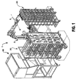
- the system 1 comprises automated means for handling and moving the cages.
- said automated means may preferably comprise a robot and, even more preferably, an anthropomorphous robotic arm 2.
- Said automated means of movement also comprise at least one gripping member 3, connected to the movable end of said robotic arm 2, and specifically structured to be able to hold the assembled cage and/or single components thereof.
- the robotic arm 2 is designed so that it can be oriented in space in order to position the gripping member 3 in any point in space, thanks to the simultaneous presence of a plurality of axes of movement A, B , C, D and E.
- the closed, soiled cages are carried with the aid of a transport cart 20, in which they are stacked tidily.
- the transport cart 20 is then placed alongside the robotic arm 2, in a position that enables the robotic arm to reach each cage. Since the transport carts of known type are normally mounted on wheels specifically to facilitate their displacement, for such a cart 20 to be suitable for use with the automated system according to the present invention special locking means must be provided to block the cart firmly in a previously-established position, so that it is held steady, in the right position in relation to the robotic arm, while said arm transfers the cages.
- Said blocking means suitably comprise a clamping hook designed to hold the cart within a corresponding slot fixed to the wall or floor, said clamping hook being suitable for being operated by an electro-hydraulic device, and said device being capable of communicating with the system's central control unit.
- the system according to the present invention also comprises a disassembly station 60.
- Said disassembly station 60 comprises a supporting surface 61 and a plurality of control sensors suitable for detecting a plurality of data and transferring it to the robot's control unit.
- the disassembly station 60 comprises a plurality of sensors. At least one sensor 62 is preferably for checking for the presence of a cage, at least one control sensor 63 checks the orientation of the cage, and at least one sensor 64 checks for the presence of the feeder. Said sensor 64 for checking for the president of a feeder may consist of an inductive sensor, for instance, that is capable of identifying the presence of any metal material.
- the lab animal containment cages are generally made of plastic, while the feeder is normally the only component of the cage to be made of metal.
- At least one blocking actuator 65 designed to retain the cage on the supporting surface 61, and a plurality of devices 66 to position the cage correctly on the supporting surface 61.
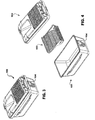
- FIGS 3 and 4 show an example of a lab animal containment cage suitable for handling by the system 1 according to the present invention.
- Said cage 100 consists substantially of three components, i.e. a tray 101 suitable for containing animals and for being filled with a material for use as bedding, a lid 102 suitable for closing the cage, and a feeder 103 that can consist of a metal grid, for instance.
- the cage may be of the type comprising a closing system with a push button control 104 for releasing the lid.
- a closing system with a push button control 104 for releasing the lid.
- One type of cage widely used in lab animal rooms involves the presence of two buttons for releasing the lid, located on two opposite sides of the cage.
- the disassembly station 60 comprises means for opening the cage, comprising an actuator 67, for instance, capable of releasing the lid 102 by means of a pressure on the buttons 104.
- an actuator 67 for instance, capable of releasing the lid 102 by means of a pressure on the buttons 104.
- the content illustrated herein as regards the lab animal containment cages may not be construed to limit the present invention in any way, because the cages may be of any, even very different shape, since the system 1 according to the present invention is easily adaptable to other types of cage.
- the robotic arm 2 of the system 1 comprises a gripper 3 suitable for holding the whole cage and each single component thereof.
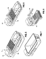
- the gripper 3 comprises a head 3d with which cage gripping means are associated, said cage gripping means comprising, for instance, a clamp consisting of two jaws 3a and 3b slidingly associated with said head 3d in the direction identified by the arrows A in figure 8a , i.e. so that they can be moved closer together or further apart.
- the gripping member 3 also comprises further gripping means for holding the feeder 103.
- Said gripping means for holding the feeder comprise at least one actuator 3g consisting of a piston terminating with a head 3e, first locator means 3h on the feeder 103 comprising, for instance, a pair of slots 3f designed to contain a stretch of the perimeter of said feeder 103, as shown in figures 8c and 8d , and at least second locator means 3c shaped like a flange, for instance, against which said head 3e (that is movable perpendicularly to said locator means 3c, in the direction B of figure 8b ) is designed to close the perimeter stretch of feeder positioned between the portions inserted in the two slots 3f. Being capable of movement perpendicular to said locator means 3c, said head 3e holds the feeder 103 by gripping a stretch of one of its ends.
- the soiled cages are generally placed on a storage device that may, for instance, consist of a transport cart 20; they may be deposited in a storage area inside the lab animal room before they are carried to the area for the disassembly and emptying of the cages.
- an extractor hood with a laminar flow 40 comprising a hopper 41 where the bedding or litter from the cage is collected, while the hood prevents the dispersion of any allergens in the environment.
- the system according to the present invention enables the automated disassembly of the cages 100.
- the cages are collected from the transport cart 20 by the robotic arm 2, the cage being held by the gripping member 3 as shown in figure 5 .
- the gripping action achieved by the two juxtaposed jaws 3a and 3b makes contact with the cage in line with two opposite lateral surfaces and the tightening of the jaws ensures the gripping of the cage.
- the cage While still assembled, the cage is thus deposited at the disassembly station 60 in line with locator devices 66 designed to orient its position.
- the sensors 62, 63 and 64 respectively detect the presence of a cage at the disassembly station 60, the orientation of said cage, and the presence of a feeder 103, and they transfer this information to the control unit governing the robotic arm 2.
- the control unit monitors the movements of the robotic arm and controls its operation.
- the blocking actuator 65 holds the cage in position on the surface 61.
- the lid 102 of the cage is released from the tray 101, while the sensor 63 checks the orientation of the cage, so that the robotic arm can grasp the lid 102 in the correct position.
- the gripping member 3 of the robotic arm 2 hold the lid 102 by means of the jaws 3a and 3b of the gripping member 3 and the lid is removed from the cage, the robotic arm 2 again moving on the strength of information relating to the orientation of the cage provided by the sensors at the disassembly station 60.
- the robotic arm 2 can then deposit the lid on a cart or delivery shelf 30, in the case of a discontinuous washing procedure, as shown in figure 1 , or directly on a conveyor belt leading into a tunnel washer 50, as shown in figure 2 , in the case of a continuous washing procedure.
- the gripper 3 of the robotic arm 2 picks up the feeder 103 with the aid of the means for the feeder.
- the sensor 64 for detecting the presence of the feeder informs the control unit of the presence or absence of the feeder so that the robotic arm can skip this phase if there is no feeder to remove.
- the control software can make the robot turn the feeder 103 upside down, so that any contents in the feeder, e.g. any food scraps remaining on its surface, can drop back into the tray 101.
- the robotic arm 2 After the robotic arm 2 has completed, where necessary, this procedure to empty the feeder 103 of any food scraps, it again deposits the feeder on the cart or delivery shelf 30 in the case of a discontinuous washing procedure, or directly on the conveyor belt leading into the tunnel washer 50, shown in figure 2 , in the case of a continuous washing procedure.
- the robot's gripping jaws 3a, 3b grasp the tray 101 (that has been released in the meantime from the constraint exerted by the blocking actuator 65), lifting the tray off the surface 61 of the disassembly station 60 and bringing it into line with the hopper 41 under the extractor hood with a laminar flow 40, where it is turned upside down in order to empty its contents into the hopper.
- the tray After the tray has been emptied, it too is loaded onto the cart or delivery shelf 30 in the case of a discontinuous washing procedure, or directly onto the conveyor belt for delivery to the tunnel washer 50 in the case of a continuous washing procedure.
- This sequence of operations or disassembly of the cages and emptying of the bedding contained in the trays is repeated automatically by the robot for every cage contained on the transport shelf 20, or other generic storage structure, and a tray sensor can be suitably provided in line with the gripper 3 too, so that the system automatically identifies the presence of a cage on the storage shelf.
- a similar system comprising a robotic arm and a re-assembly station can be provided at the outlet from the tunnel washer so as to automate the procedure for the reassembly of the cages too, after they have been washed - procedures that otherwise have to be completed by hand.
- the system according to the present invention enables the completely automated disassembly and emptying of the cages without any need for the operator to take any manual action, thereby optimising the research personnel's activities at the laboratory by leaving them free to dedicate themselves to their research activities.
- Another object achieved by the system according to the present invention is that of drastically reducing the time it takes to disassemble, empty and wash the cages, with a consequent optimisation of the time available for the laboratory activities, and consequently also of the related costs.
- the automated system reduces to a minimum any risk of the operator coming into contact with allergens and dust in relation to the devices used in the lab animal room to contain the animals and their bedding.
- system according to the present invention may also be used to reassemble the cages at the end of the washing procedure.
- a possible application might, for instance, include the presence of one system according to the present invention at the inlet to a continuous tunnel washer, such as the one described herein, and the presence of a second system according to the present invention that performs the same operations in reverse order, reassembling the cages when they exit from the tunnel washer.
- the reassembly of the cages might be handled automatically by the system according to the present invention, controlled by suitable software, also in combination with discontinuous washing machines.
Landscapes
- Life Sciences & Earth Sciences (AREA)
- Environmental Sciences (AREA)
- Zoology (AREA)
- Engineering & Computer Science (AREA)
- Clinical Laboratory Science (AREA)
- Animal Behavior & Ethology (AREA)
- Health & Medical Sciences (AREA)
- General Health & Medical Sciences (AREA)
- Mechanical Engineering (AREA)
- Animal Husbandry (AREA)
- Biodiversity & Conservation Biology (AREA)
- Robotics (AREA)
- Housing For Livestock And Birds (AREA)
- Feeding And Watering For Cattle Raising And Animal Husbandry (AREA)
- Refuse Collection And Transfer (AREA)
Claims (13)
- System zur Handhabung von Tierkäfigen (100), die mindestens einen Käfigboden (101) und einen Käfigdeckel (102) aufweisen, in einem Tierraum, umfassend:- automatisierte Einrichtungen (2, 3) zum Handhaben, Bewegen und Demontieren von Käfigen;- mindestens eine Demontagestation (60), um solche Käfige während der Demontage abzulegen, und mit verschiedenen Detektionssensoren (62, 63, 64) vorgesehen, um das Vorhandensein des Käfigs und Käfigpositionsparameter zu detektieren;- eine Steuereinheit solcher automatisierter Einrichtungen (2, 3), die das Signal entsprechend den Parametern erfasst, die durch solche Detektionssensoren (62, 63, 64) detektiert werden, und die solche automatisierten Einrichtungen (2, 3) entsprechend solchen Positionsparametern steuert.
- System nach dem oben erwähnten Anspruch, dadurch gekennzeichnet, dass die automatisierten Einrichtungen einen Roboterarm (2) aufweisen, der mit einem Greifer (3) vorgesehen ist.
- System nach dem vorangehenden Anspruch, dadurch gekennzeichnet, dass der Greifer (3) einen Kopf (3d) mit verbundenem Greifer zum Aufnehmen eines Käfigs (100) oder von Teilen (101, 102) von einem Käfig aufweist, und mindestens ein Paar von Armen (3a, 3b) aufweist, die verschiebbar mit einem solchen Kopf (3d) verbunden sind, damit die Beiden angenähert oder getrennt werden.
- System nach Anspruch 2 oder 3, dadurch gekennzeichnet, dass der Greifer auch weitere Greifeinrichtungen (3c, 3e, 3f, 3g, 3h) aufweist, um einen weiteren Teil des Käfigs zu greifen, wobei der weitere Teil ein Feeder (103) ist.
- System nach dem vorangehenden Anspruch, dadurch gekennzeichnet, dass die Feedergreifeinrichtung (103) mindestens erste Geräte (3h) enthält, die eine oder mehrere Aussparungen (3f) aufweisen, die geeignet zum Erfassen eines Teils eines solchen Feeders (103) sind.
- System nach dem vorangehenden Anspruch, dadurch gekennzeichnet, dass die Feedergreifeinrichtung auch zweite Geräte enthält, die mindestens ein Element, das als Flansch (3c) geformt ist, und das vorne an einem solchen Kopf (3d) positioniert ist, aufweisen.
- System nach dem vorangehenden Anspruch, dadurch gekennzeichnet, dass die Greifeinrichtung um den Feeder (103) zu greifen auch mindestens einen Aktor (3g) enthält, der geeignet ist, um einen Kopf (3e) in einer Richtung, die im Wesentlichen senkrecht zu einer solchen Flanschrichtung (3c) ist, zu bewegen, und, dass solch ein Kopf (3e) in der Lage ist, um an einem solchen Gerät (3c) festzumachen, an wenigstens einem dezentraler Abschnitt eines solchen Feeders (103), der vorher in solche Gehäuse der ersten Einrichtung (3h) eingepasst wird.
- System nach dem vorangehenden Anspruch, dadurch gekennzeichnet, dass die Demontagestation (60) mindestens einen Käfigpräsenzkontrollsensor (62) enthält.
- System nach dem vorangehenden Anspruch, dadurch gekennzeichnet, dass die Demontagestation (60) mindestens einen Käfigausrichtungskontrollsensor (63) enthält.
- System nach dem vorangehenden Anspruch, dadurch gekennzeichnet, dass die Demontagestation (60) auch mindestens einen Feederpräsenzdetektionssensor (64) enthält.
- System nach dem vorangehenden Anspruch, dadurch gekennzeichnet, dass eine solche Demontagestation (60) auch mindestens einen Verriegelungsaktor (65), der geeignet ist, um sicher einen Käfig in der Ebene (61) von einer solchen Demontagestation zu halten, und verschiedene Geräte (66) zur korrekten Positionierung des Käfigs in der Ebene (61) enthält.
- Verfahren zur Handhabung von Tierkäfigen (100), die mindestens einen Käfigboden (101) und einen Käfigdeckel (102) aufweisen, in einem Tierraum, umfassend die folgenden Schritte:- Anordnen von einem oder mehreren Käfigen (100) montiert oder demontiert auf einer Tragestruktur;- Anordnen von verschiedenen Sensoren (62, 63, 64), die geeignet sind, um die Position in dem Raum und die Ausrichtung von solchen montierten Käfigen (100) oder demontierten Komponenten (101, 102, 103) von solchen Käfigen zu detektieren;- Anordnen einer zentralen Steuereinheit, die geeignet ist, um Signale zu detektieren, die von den Sensoren (62, 63, 64) kommen;- Anordnen von automatisierten Einrichtungen (2, 3) zum Handhaben und/oder Bewegen der Käfige,- Demontieren von solchen Käfigen (100) oder Montieren von demontierten Komponenten (101, 102, 103) von solchen Käfigen durch solche automatisierten Einrichtungen (2, 3), die durch eine solche zentrale Steuereinheit auf der Basis von Signalen gesteuert werden, die von solchen Sensoren kommen.
- Verfahren nach dem vorangehenden Anspruch, weiter aufweisend die folgenden Schritte:- Anordnen von verschiedenen Käfigen (100) montiert und geordnet in einer Lagerstruktur (20);- Aufnehmen eines Käfigs (100) von einer solchen Lagerstruktur (20) durch automatisierte Einrichtungen (2, 3) zum Handhaben und Bewegen von Käfigen und gesteuert von einer zentralen Steuereinheit;- Positionieren von einem solchen Käfig durch solche automatisierte Handhabungseinrichtungen (2, 3) auf einer Demontagestation (60);- Detektieren des Vorhandenseins und der Ausrichtung des Käfigs auf der Demontagestation (60) durch Sensoren (62, 63), die mit einer solchen zentralen Steuereinheit kommunizieren;- Losmachen des Deckels durch ein oder mehrere Käfigöffnungsgeräte (66, 67), die auf der Demontagestation (60) vorgesehen sind, und durch eine solche zentrale Steuereinheit gesteuert werden;- Greifen des Deckels (102) von einem solchen Käfig (100), mit der Hilfe von solchen automatisierten Einrichtungen (2, 3), und trennen des Deckels von dem Käfigboden, indem er auf einen Wagen oder ein Präsentationsgerüst (30) zum Stapeln demontierter Käfige oder direkt auf ein Waschstraßenförderband (50) gelegt wird;- Detektieren des Vorhandenseins eines Feeders (103) durch einen Feederdetektionssensor (64), der mit einer solchen zentralen Steuereinheit kommuniziert, und, in dem Fall des Vorhandenseins des Feeders, greifen des Feeders (103) eines solchen Käfigs durch solche automatisierte Einrichtungen (2, 3) und ihn von dem Käfig trennen, indem er auf einen Wagen oder ein Präsentationsgerüst (30) zur Speicherung von demontierten Käfigen oder direkt auf ein Waschstraßenförderband (50) gelegt wird;- Greifen des Käfigbodens (101) eines solchen Käfigs durch solche automatisierte Einrichtungen (2, 3) und Leeren seines Inhalts durch Umkippen über einem Behälter (41), der die Streu einsammelt, und Fördern eines solchen Käfigbodens (101) auf einem Wagen oder Präsentationsgerüst (30) zum Sammeln demontierter Käfigböden oder direkt auf einem Waschstraßenförderband;- Wiederholen der vorangehenden Schritte für jeden Käfig (100), der in einem solchen Lagergerät (20) gestapelt ist.
Applications Claiming Priority (2)
| Application Number | Priority Date | Filing Date | Title |
|---|---|---|---|
| ITMI2009A001521A IT1395508B1 (it) | 2009-09-01 | 2009-09-01 | Sistema e metodo automatizzato per lo smontaggio, manipolazione, rimontaggio di dispositivi di contenimento degli animali per uno stabulario |
| PCT/EP2010/062793 WO2011026859A1 (en) | 2009-09-01 | 2010-09-01 | An automated system and method for disassembling, handling and reassembling devices for containing animals in a lab animal room |
Publications (2)
| Publication Number | Publication Date |
|---|---|
| EP2473322A1 EP2473322A1 (de) | 2012-07-11 |
| EP2473322B1 true EP2473322B1 (de) | 2013-09-11 |
Family
ID=41728223
Family Applications (1)
| Application Number | Title | Priority Date | Filing Date |
|---|---|---|---|
| EP10759828.6A Active EP2473322B1 (de) | 2009-09-01 | 2010-09-01 | Automatisiertes system und verfahren zur demontage, handhabung und erneuten montage von vorrichtungen zum eingrenzen von tieren in einem laborraum |
Country Status (5)
| Country | Link |
|---|---|
| US (1) | US8714110B2 (de) |
| EP (1) | EP2473322B1 (de) |
| CA (1) | CA2772803A1 (de) |
| IT (1) | IT1395508B1 (de) |
| WO (1) | WO2011026859A1 (de) |
Families Citing this family (14)
| Publication number | Priority date | Publication date | Assignee | Title |
|---|---|---|---|---|
| US20120272919A1 (en) * | 2011-04-26 | 2012-11-01 | The University Of Utah | Animal euthanasia systems and methods |
| JP6065238B2 (ja) * | 2011-09-30 | 2017-01-25 | テクニプラスト ソシエタ ペル アチオニ | 檻の状況及び存在を自動検知するための電子装置、該装置を備えるシステム、及び方法 |
| US9545078B1 (en) * | 2012-06-07 | 2017-01-17 | Lely Patent N.V. | Electro-hydraulical actuator for a robot arm |
| KR101376977B1 (ko) * | 2013-12-23 | 2014-03-26 | (주) 쓰리샤인 | 실험동물의 오염·감염방지를 위한 자동관리시스템 |
| KR101566608B1 (ko) * | 2014-01-28 | 2015-11-06 | 호서대학교 산학협력단 | 자동 동물 사육 장치 |
| EP3203831B1 (de) | 2014-10-08 | 2018-09-12 | Steelco S.p.A. | Vorrichtung und verfahren zur verarbeitung von vorrichtungen zum zurückhalten von tieren |
| WO2016071855A1 (en) * | 2014-11-04 | 2016-05-12 | The Governors Of The University Of Alberta | Systems and methods for behavioral and task training of laboratory animals |
| DE102018114037A1 (de) * | 2018-06-12 | 2019-12-12 | Salmet Gmbh & Co Kg | Käfigbatterie für die Geflügelhaltung |
| IT201900002331A1 (it) | 2019-02-18 | 2020-08-18 | Steelco Spa | Apparato di ribaltamento per corpi di contenimento scatolari e relativo metodo |
| JP7240668B2 (ja) * | 2019-02-28 | 2023-03-16 | 伊勢屋金網工業株式会社 | 動物用ケージの組立システム及び組立方法 |
| IT202000010921A1 (it) * | 2020-05-13 | 2021-11-13 | Tecniplast Spa | Gabbietta per animali da laboratorio e scaffalatura atta ad alloggiare una pluralità di gabbiette per animali da laboratorio |
| CN112655587B (zh) * | 2020-11-26 | 2023-06-02 | 西安医学院 | 一种全自动智能水迷宫实验装置 |
| CN113996349B (zh) * | 2021-10-18 | 2023-01-20 | 绍兴上虞申丰制冷设备有限公司 | 一种分隔式环境模拟实验箱 |
| IL295689A (en) * | 2022-08-16 | 2024-03-01 | Baccara Geva Agriculture Corporation Soc Ltd | Automated hydroponic fodder growing system and method of operation therefor, seed growing tray, and seed batch dispenser |
Family Cites Families (5)
| Publication number | Priority date | Publication date | Assignee | Title |
|---|---|---|---|---|
| JP2648794B2 (ja) * | 1991-07-08 | 1997-09-03 | 富士通株式会社 | ロボットの把持装置 |
| US5735664A (en) * | 1995-12-29 | 1998-04-07 | Jerome; Wallace H. | Apparatus and method for unloading poultry from multilayer containers |
| WO2001024618A1 (en) * | 1999-10-01 | 2001-04-12 | Steris Inc. | Transfer system for animal cages, baskets, and pallets |
| US7114462B2 (en) * | 2004-01-12 | 2006-10-03 | Matrix Scientific, Llc | Automated cage cleaning apparatus and method |
| US20060185611A1 (en) * | 2004-12-21 | 2006-08-24 | Kent Copeland | Robotic animal handling system for biosafety laboratories |
-
2009
- 2009-09-01 IT ITMI2009A001521A patent/IT1395508B1/it active
- 2009-11-05 US US12/613,021 patent/US8714110B2/en active Active
-
2010
- 2010-09-01 CA CA2772803A patent/CA2772803A1/en not_active Abandoned
- 2010-09-01 WO PCT/EP2010/062793 patent/WO2011026859A1/en not_active Ceased
- 2010-09-01 EP EP10759828.6A patent/EP2473322B1/de active Active
Also Published As
| Publication number | Publication date |
|---|---|
| US20110054669A1 (en) | 2011-03-03 |
| WO2011026859A1 (en) | 2011-03-10 |
| IT1395508B1 (it) | 2012-09-28 |
| CA2772803A1 (en) | 2011-03-10 |
| ITMI20091521A1 (it) | 2011-03-02 |
| EP2473322A1 (de) | 2012-07-11 |
| US8714110B2 (en) | 2014-05-06 |
Similar Documents
| Publication | Publication Date | Title |
|---|---|---|
| EP2473322B1 (de) | Automatisiertes system und verfahren zur demontage, handhabung und erneuten montage von vorrichtungen zum eingrenzen von tieren in einem laborraum | |
| US20180133893A1 (en) | Sample treatment system | |
| US11660159B2 (en) | Instrument tray for surgical instruments | |
| US7325667B1 (en) | Systems and methods for feeding articles to and removing articles from an automatic washer | |
| JP7337958B2 (ja) | 敏感な製品を取り扱う設備、特に包装設備 | |
| EP2650237B1 (de) | Verfahren und Vorrichtung zum Sammeln von Produkten aus Produktbehältern beim Sammeln von Behältern nach Bestellungen | |
| RS63326B1 (sr) | Postupak i sistem za pripremanje robe koja je već stavljena u složive kontejnere za komadnu robu na paletama sa artiklima u skladištu sa paletama na ciljnu paletu | |
| KR20180084059A (ko) | 보관 컨테이너, 보관 상자 및 보관 장치 | |
| JP2005526977A5 (de) | ||
| JP2004077395A (ja) | 自動保管装置 | |
| US8342124B2 (en) | Apparatus and method for cleaning a milking system | |
| WO2005067565A2 (en) | Automated cage cleaning apparatus and method | |
| CN211748753U (zh) | 烹饪系统 | |
| EP3203831B1 (de) | Vorrichtung und verfahren zur verarbeitung von vorrichtungen zum zurückhalten von tieren | |
| DK174193B1 (da) | Robotanlæg | |
| CA3204605C (en) | BARRIER SYSTEM WITH A HANDLING DEVICE FOR AUTOMATED SAMPLING AND AUTOMATED SAMPLING METHOD | |
| JP4007204B2 (ja) | ロボットシステム | |
| WO2001024618A1 (en) | Transfer system for animal cages, baskets, and pallets | |
| EP4727339A2 (de) | System und verfahren zur verarbeitung von pflanzenmaterial | |
| JP7321992B2 (ja) | 食器洗浄補助装置および食器洗浄システム | |
| CN119997987A (zh) | 处理无菌物品容器系统的方法 | |
| KR101740568B1 (ko) | 멀티타입 미생물 포자 채집장치 | |
| JP2023100453A (ja) | 食器洗浄補助装置および食器洗浄システム | |
| EP2674093B1 (de) | Vorrichtung zum Laden einer Waschmaschine mit zu waschenden Komponenten und Gerät mit dieser Vorrichtung | |
| CN212421331U (zh) | 机械手爪 |
Legal Events
| Date | Code | Title | Description |
|---|---|---|---|
| PUAI | Public reference made under article 153(3) epc to a published international application that has entered the european phase |
Free format text: ORIGINAL CODE: 0009012 |
|
| 17P | Request for examination filed |
Effective date: 20120330 |
|
| AK | Designated contracting states |
Kind code of ref document: A1 Designated state(s): AL AT BE BG CH CY CZ DE DK EE ES FI FR GB GR HR HU IE IS IT LI LT LU LV MC MK MT NL NO PL PT RO SE SI SK SM TR |
|
| DAX | Request for extension of the european patent (deleted) | ||
| GRAP | Despatch of communication of intention to grant a patent |
Free format text: ORIGINAL CODE: EPIDOSNIGR1 |
|
| INTG | Intention to grant announced |
Effective date: 20130408 |
|
| GRAS | Grant fee paid |
Free format text: ORIGINAL CODE: EPIDOSNIGR3 |
|
| GRAA | (expected) grant |
Free format text: ORIGINAL CODE: 0009210 |
|
| AK | Designated contracting states |
Kind code of ref document: B1 Designated state(s): AL AT BE BG CH CY CZ DE DK EE ES FI FR GB GR HR HU IE IS IT LI LT LU LV MC MK MT NL NO PL PT RO SE SI SK SM TR |
|
| REG | Reference to a national code |
Ref country code: GB Ref legal event code: FG4D |
|
| REG | Reference to a national code |
Ref country code: CH Ref legal event code: EP |
|
| REG | Reference to a national code |
Ref country code: AT Ref legal event code: REF Ref document number: 631352 Country of ref document: AT Kind code of ref document: T Effective date: 20130915 |
|
| REG | Reference to a national code |
Ref country code: IE Ref legal event code: FG4D |
|
| REG | Reference to a national code |
Ref country code: DE Ref legal event code: R096 Ref document number: 602010010241 Country of ref document: DE Effective date: 20131107 |
|
| REG | Reference to a national code |
Ref country code: SE Ref legal event code: TRGR |
|
| PG25 | Lapsed in a contracting state [announced via postgrant information from national office to epo] |
Ref country code: NO Free format text: LAPSE BECAUSE OF FAILURE TO SUBMIT A TRANSLATION OF THE DESCRIPTION OR TO PAY THE FEE WITHIN THE PRESCRIBED TIME-LIMIT Effective date: 20131211 Ref country code: CY Free format text: LAPSE BECAUSE OF FAILURE TO SUBMIT A TRANSLATION OF THE DESCRIPTION OR TO PAY THE FEE WITHIN THE PRESCRIBED TIME-LIMIT Effective date: 20130904 Ref country code: LT Free format text: LAPSE BECAUSE OF FAILURE TO SUBMIT A TRANSLATION OF THE DESCRIPTION OR TO PAY THE FEE WITHIN THE PRESCRIBED TIME-LIMIT Effective date: 20130911 Ref country code: HR Free format text: LAPSE BECAUSE OF FAILURE TO SUBMIT A TRANSLATION OF THE DESCRIPTION OR TO PAY THE FEE WITHIN THE PRESCRIBED TIME-LIMIT Effective date: 20130911 |
|
| REG | Reference to a national code |
Ref country code: NL Ref legal event code: VDEP Effective date: 20130911 |
|
| REG | Reference to a national code |
Ref country code: AT Ref legal event code: MK05 Ref document number: 631352 Country of ref document: AT Kind code of ref document: T Effective date: 20130911 |
|
| REG | Reference to a national code |
Ref country code: LT Ref legal event code: MG4D |
|
| PG25 | Lapsed in a contracting state [announced via postgrant information from national office to epo] |
Ref country code: FI Free format text: LAPSE BECAUSE OF FAILURE TO SUBMIT A TRANSLATION OF THE DESCRIPTION OR TO PAY THE FEE WITHIN THE PRESCRIBED TIME-LIMIT Effective date: 20130911 Ref country code: SI Free format text: LAPSE BECAUSE OF FAILURE TO SUBMIT A TRANSLATION OF THE DESCRIPTION OR TO PAY THE FEE WITHIN THE PRESCRIBED TIME-LIMIT Effective date: 20130911 Ref country code: LV Free format text: LAPSE BECAUSE OF FAILURE TO SUBMIT A TRANSLATION OF THE DESCRIPTION OR TO PAY THE FEE WITHIN THE PRESCRIBED TIME-LIMIT Effective date: 20130911 Ref country code: GR Free format text: LAPSE BECAUSE OF FAILURE TO SUBMIT A TRANSLATION OF THE DESCRIPTION OR TO PAY THE FEE WITHIN THE PRESCRIBED TIME-LIMIT Effective date: 20131212 |
|
| PG25 | Lapsed in a contracting state [announced via postgrant information from national office to epo] |
Ref country code: CY Free format text: LAPSE BECAUSE OF FAILURE TO SUBMIT A TRANSLATION OF THE DESCRIPTION OR TO PAY THE FEE WITHIN THE PRESCRIBED TIME-LIMIT Effective date: 20130911 Ref country code: BE Free format text: LAPSE BECAUSE OF FAILURE TO SUBMIT A TRANSLATION OF THE DESCRIPTION OR TO PAY THE FEE WITHIN THE PRESCRIBED TIME-LIMIT Effective date: 20130911 |
|
| PG25 | Lapsed in a contracting state [announced via postgrant information from national office to epo] |
Ref country code: SK Free format text: LAPSE BECAUSE OF FAILURE TO SUBMIT A TRANSLATION OF THE DESCRIPTION OR TO PAY THE FEE WITHIN THE PRESCRIBED TIME-LIMIT Effective date: 20130911 Ref country code: NL Free format text: LAPSE BECAUSE OF FAILURE TO SUBMIT A TRANSLATION OF THE DESCRIPTION OR TO PAY THE FEE WITHIN THE PRESCRIBED TIME-LIMIT Effective date: 20130911 Ref country code: CZ Free format text: LAPSE BECAUSE OF FAILURE TO SUBMIT A TRANSLATION OF THE DESCRIPTION OR TO PAY THE FEE WITHIN THE PRESCRIBED TIME-LIMIT Effective date: 20130911 Ref country code: IS Free format text: LAPSE BECAUSE OF FAILURE TO SUBMIT A TRANSLATION OF THE DESCRIPTION OR TO PAY THE FEE WITHIN THE PRESCRIBED TIME-LIMIT Effective date: 20140111 Ref country code: EE Free format text: LAPSE BECAUSE OF FAILURE TO SUBMIT A TRANSLATION OF THE DESCRIPTION OR TO PAY THE FEE WITHIN THE PRESCRIBED TIME-LIMIT Effective date: 20130911 Ref country code: RO Free format text: LAPSE BECAUSE OF FAILURE TO SUBMIT A TRANSLATION OF THE DESCRIPTION OR TO PAY THE FEE WITHIN THE PRESCRIBED TIME-LIMIT Effective date: 20130911 |
|
| PG25 | Lapsed in a contracting state [announced via postgrant information from national office to epo] |
Ref country code: ES Free format text: LAPSE BECAUSE OF FAILURE TO SUBMIT A TRANSLATION OF THE DESCRIPTION OR TO PAY THE FEE WITHIN THE PRESCRIBED TIME-LIMIT Effective date: 20130911 Ref country code: PL Free format text: LAPSE BECAUSE OF FAILURE TO SUBMIT A TRANSLATION OF THE DESCRIPTION OR TO PAY THE FEE WITHIN THE PRESCRIBED TIME-LIMIT Effective date: 20130911 Ref country code: AT Free format text: LAPSE BECAUSE OF FAILURE TO SUBMIT A TRANSLATION OF THE DESCRIPTION OR TO PAY THE FEE WITHIN THE PRESCRIBED TIME-LIMIT Effective date: 20130911 |
|
| REG | Reference to a national code |
Ref country code: DE Ref legal event code: R097 Ref document number: 602010010241 Country of ref document: DE |
|
| PG25 | Lapsed in a contracting state [announced via postgrant information from national office to epo] |
Ref country code: PT Free format text: LAPSE BECAUSE OF FAILURE TO SUBMIT A TRANSLATION OF THE DESCRIPTION OR TO PAY THE FEE WITHIN THE PRESCRIBED TIME-LIMIT Effective date: 20140113 |
|
| PLBE | No opposition filed within time limit |
Free format text: ORIGINAL CODE: 0009261 |
|
| STAA | Information on the status of an ep patent application or granted ep patent |
Free format text: STATUS: NO OPPOSITION FILED WITHIN TIME LIMIT |
|
| 26N | No opposition filed |
Effective date: 20140612 |
|
| REG | Reference to a national code |
Ref country code: DE Ref legal event code: R097 Ref document number: 602010010241 Country of ref document: DE Effective date: 20140612 |
|
| PG25 | Lapsed in a contracting state [announced via postgrant information from national office to epo] |
Ref country code: DK Free format text: LAPSE BECAUSE OF FAILURE TO SUBMIT A TRANSLATION OF THE DESCRIPTION OR TO PAY THE FEE WITHIN THE PRESCRIBED TIME-LIMIT Effective date: 20130911 |
|
| REG | Reference to a national code |
Ref country code: DE Ref legal event code: R119 Ref document number: 602010010241 Country of ref document: DE |
|
| PG25 | Lapsed in a contracting state [announced via postgrant information from national office to epo] |
Ref country code: MC Free format text: LAPSE BECAUSE OF FAILURE TO SUBMIT A TRANSLATION OF THE DESCRIPTION OR TO PAY THE FEE WITHIN THE PRESCRIBED TIME-LIMIT Effective date: 20130911 Ref country code: LU Free format text: LAPSE BECAUSE OF FAILURE TO SUBMIT A TRANSLATION OF THE DESCRIPTION OR TO PAY THE FEE WITHIN THE PRESCRIBED TIME-LIMIT Effective date: 20140901 |
|
| REG | Reference to a national code |
Ref country code: CH Ref legal event code: PL |
|
| GBPC | Gb: european patent ceased through non-payment of renewal fee |
Effective date: 20140901 |
|
| REG | Reference to a national code |
Ref country code: IE Ref legal event code: MM4A |
|
| REG | Reference to a national code |
Ref country code: DE Ref legal event code: R119 Ref document number: 602010010241 Country of ref document: DE Effective date: 20150401 |
|
| REG | Reference to a national code |
Ref country code: FR Ref legal event code: ST Effective date: 20150529 |
|
| PG25 | Lapsed in a contracting state [announced via postgrant information from national office to epo] |
Ref country code: GB Free format text: LAPSE BECAUSE OF NON-PAYMENT OF DUE FEES Effective date: 20140901 Ref country code: CH Free format text: LAPSE BECAUSE OF NON-PAYMENT OF DUE FEES Effective date: 20140930 Ref country code: DE Free format text: LAPSE BECAUSE OF NON-PAYMENT OF DUE FEES Effective date: 20150401 Ref country code: LI Free format text: LAPSE BECAUSE OF NON-PAYMENT OF DUE FEES Effective date: 20140930 |
|
| PG25 | Lapsed in a contracting state [announced via postgrant information from national office to epo] |
Ref country code: IE Free format text: LAPSE BECAUSE OF NON-PAYMENT OF DUE FEES Effective date: 20140901 Ref country code: FR Free format text: LAPSE BECAUSE OF NON-PAYMENT OF DUE FEES Effective date: 20140930 |
|
| PG25 | Lapsed in a contracting state [announced via postgrant information from national office to epo] |
Ref country code: SM Free format text: LAPSE BECAUSE OF FAILURE TO SUBMIT A TRANSLATION OF THE DESCRIPTION OR TO PAY THE FEE WITHIN THE PRESCRIBED TIME-LIMIT Effective date: 20130911 |
|
| PG25 | Lapsed in a contracting state [announced via postgrant information from national office to epo] |
Ref country code: BG Free format text: LAPSE BECAUSE OF FAILURE TO SUBMIT A TRANSLATION OF THE DESCRIPTION OR TO PAY THE FEE WITHIN THE PRESCRIBED TIME-LIMIT Effective date: 20130911 Ref country code: MT Free format text: LAPSE BECAUSE OF FAILURE TO SUBMIT A TRANSLATION OF THE DESCRIPTION OR TO PAY THE FEE WITHIN THE PRESCRIBED TIME-LIMIT Effective date: 20130911 |
|
| PG25 | Lapsed in a contracting state [announced via postgrant information from national office to epo] |
Ref country code: TR Free format text: LAPSE BECAUSE OF FAILURE TO SUBMIT A TRANSLATION OF THE DESCRIPTION OR TO PAY THE FEE WITHIN THE PRESCRIBED TIME-LIMIT Effective date: 20130911 Ref country code: HU Free format text: LAPSE BECAUSE OF FAILURE TO SUBMIT A TRANSLATION OF THE DESCRIPTION OR TO PAY THE FEE WITHIN THE PRESCRIBED TIME-LIMIT; INVALID AB INITIO Effective date: 20100901 |
|
| PG25 | Lapsed in a contracting state [announced via postgrant information from national office to epo] |
Ref country code: MK Free format text: LAPSE BECAUSE OF FAILURE TO SUBMIT A TRANSLATION OF THE DESCRIPTION OR TO PAY THE FEE WITHIN THE PRESCRIBED TIME-LIMIT Effective date: 20130911 |
|
| PG25 | Lapsed in a contracting state [announced via postgrant information from national office to epo] |
Ref country code: AL Free format text: LAPSE BECAUSE OF FAILURE TO SUBMIT A TRANSLATION OF THE DESCRIPTION OR TO PAY THE FEE WITHIN THE PRESCRIBED TIME-LIMIT Effective date: 20130911 |
|
| P01 | Opt-out of the competence of the unified patent court (upc) registered |
Effective date: 20230525 |
|
| PGFP | Annual fee paid to national office [announced via postgrant information from national office to epo] |
Ref country code: IT Payment date: 20250806 Year of fee payment: 16 |
|
| PGFP | Annual fee paid to national office [announced via postgrant information from national office to epo] |
Ref country code: SE Payment date: 20250702 Year of fee payment: 16 |