EP2473381B1 - Beifahrer-frontgassack - Google Patents
Beifahrer-frontgassack Download PDFInfo
- Publication number
- EP2473381B1 EP2473381B1 EP10754275.5A EP10754275A EP2473381B1 EP 2473381 B1 EP2473381 B1 EP 2473381B1 EP 10754275 A EP10754275 A EP 10754275A EP 2473381 B1 EP2473381 B1 EP 2473381B1
- Authority
- EP
- European Patent Office
- Prior art keywords
- passenger
- airbag
- impact surface
- section
- front airbag
- Prior art date
- Legal status (The legal status is an assumption and is not a legal conclusion. Google has not performed a legal analysis and makes no representation as to the accuracy of the status listed.)
- Active
Links
- 238000001514 detection method Methods 0.000 claims description 3
- 230000000717 retained effect Effects 0.000 claims 1
- 210000004197 pelvis Anatomy 0.000 description 4
- 210000000038 chest Anatomy 0.000 description 3
- 238000003780 insertion Methods 0.000 description 2
- 230000037431 insertion Effects 0.000 description 2
- 238000004519 manufacturing process Methods 0.000 description 2
- 238000009958 sewing Methods 0.000 description 2
- 230000006978 adaptation Effects 0.000 description 1
- 238000004026 adhesive bonding Methods 0.000 description 1
- 238000005520 cutting process Methods 0.000 description 1
- 238000002474 experimental method Methods 0.000 description 1
- 238000007373 indentation Methods 0.000 description 1
- 238000005304 joining Methods 0.000 description 1
- 230000014759 maintenance of location Effects 0.000 description 1
- 238000000034 method Methods 0.000 description 1
- 230000000452 restraining effect Effects 0.000 description 1
- 210000000115 thoracic cavity Anatomy 0.000 description 1
- 238000003466 welding Methods 0.000 description 1
Images


Classifications
-
- B—PERFORMING OPERATIONS; TRANSPORTING
- B60—VEHICLES IN GENERAL
- B60R—VEHICLES, VEHICLE FITTINGS, OR VEHICLE PARTS, NOT OTHERWISE PROVIDED FOR
- B60R21/00—Arrangements or fittings on vehicles for protecting or preventing injuries to occupants or pedestrians in case of accidents or other traffic risks
- B60R21/02—Occupant safety arrangements or fittings, e.g. crash pads
- B60R21/16—Inflatable occupant restraints or confinements designed to inflate upon impact or impending impact, e.g. air bags
- B60R21/23—Inflatable members
- B60R21/231—Inflatable members characterised by their shape, construction or spatial configuration
-
- B—PERFORMING OPERATIONS; TRANSPORTING
- B60—VEHICLES IN GENERAL
- B60R—VEHICLES, VEHICLE FITTINGS, OR VEHICLE PARTS, NOT OTHERWISE PROVIDED FOR
- B60R21/00—Arrangements or fittings on vehicles for protecting or preventing injuries to occupants or pedestrians in case of accidents or other traffic risks
- B60R21/02—Occupant safety arrangements or fittings, e.g. crash pads
- B60R21/16—Inflatable occupant restraints or confinements designed to inflate upon impact or impending impact, e.g. air bags
- B60R21/20—Arrangements for storing inflatable members in their non-use or deflated condition; Arrangement or mounting of air bag modules or components
- B60R21/205—Arrangements for storing inflatable members in their non-use or deflated condition; Arrangement or mounting of air bag modules or components in dashboards
-
- B—PERFORMING OPERATIONS; TRANSPORTING
- B60—VEHICLES IN GENERAL
- B60R—VEHICLES, VEHICLE FITTINGS, OR VEHICLE PARTS, NOT OTHERWISE PROVIDED FOR
- B60R21/00—Arrangements or fittings on vehicles for protecting or preventing injuries to occupants or pedestrians in case of accidents or other traffic risks
- B60R21/02—Occupant safety arrangements or fittings, e.g. crash pads
- B60R21/16—Inflatable occupant restraints or confinements designed to inflate upon impact or impending impact, e.g. air bags
- B60R21/23—Inflatable members
- B60R21/235—Inflatable members characterised by their material
-
- B—PERFORMING OPERATIONS; TRANSPORTING
- B60—VEHICLES IN GENERAL
- B60R—VEHICLES, VEHICLE FITTINGS, OR VEHICLE PARTS, NOT OTHERWISE PROVIDED FOR
- B60R22/00—Safety belts or body harnesses in vehicles
- B60R22/48—Control systems, alarms, or interlock systems, for the correct application of the belt or harness
-
- B—PERFORMING OPERATIONS; TRANSPORTING
- B60—VEHICLES IN GENERAL
- B60R—VEHICLES, VEHICLE FITTINGS, OR VEHICLE PARTS, NOT OTHERWISE PROVIDED FOR
- B60R21/00—Arrangements or fittings on vehicles for protecting or preventing injuries to occupants or pedestrians in case of accidents or other traffic risks
- B60R2021/003—Arrangements or fittings on vehicles for protecting or preventing injuries to occupants or pedestrians in case of accidents or other traffic risks characterised by occupant or pedestian
- B60R2021/0039—Body parts of the occupant or pedestrian affected by the accident
- B60R2021/0048—Head
-
- B—PERFORMING OPERATIONS; TRANSPORTING
- B60—VEHICLES IN GENERAL
- B60R—VEHICLES, VEHICLE FITTINGS, OR VEHICLE PARTS, NOT OTHERWISE PROVIDED FOR
- B60R21/00—Arrangements or fittings on vehicles for protecting or preventing injuries to occupants or pedestrians in case of accidents or other traffic risks
- B60R2021/003—Arrangements or fittings on vehicles for protecting or preventing injuries to occupants or pedestrians in case of accidents or other traffic risks characterised by occupant or pedestian
- B60R2021/0039—Body parts of the occupant or pedestrian affected by the accident
- B60R2021/0058—Shoulders
-
- B—PERFORMING OPERATIONS; TRANSPORTING
- B60—VEHICLES IN GENERAL
- B60R—VEHICLES, VEHICLE FITTINGS, OR VEHICLE PARTS, NOT OTHERWISE PROVIDED FOR
- B60R22/00—Safety belts or body harnesses in vehicles
- B60R22/48—Control systems, alarms, or interlock systems, for the correct application of the belt or harness
- B60R2022/4808—Sensing means arrangements therefor
- B60R2022/4816—Sensing means arrangements therefor for sensing locking of buckle
-
- B—PERFORMING OPERATIONS; TRANSPORTING
- B60—VEHICLES IN GENERAL
- B60R—VEHICLES, VEHICLE FITTINGS, OR VEHICLE PARTS, NOT OTHERWISE PROVIDED FOR
- B60R22/00—Safety belts or body harnesses in vehicles
- B60R22/48—Control systems, alarms, or interlock systems, for the correct application of the belt or harness
- B60R2022/4808—Sensing means arrangements therefor
- B60R2022/4841—Sensing means arrangements therefor for sensing belt tension
Definitions
- the invention relates to a passenger front airbag according to the preamble of claim 1 and to a vehicle having such a front passenger airbag according to claim 10.
- So-called passenger front airbags are widely used in the automotive industry and serve the protection of the passenger, namely in particular the protection of his head, in a head-on collision or a laterally offset frontal collision.
- a passenger front airbag is in the instrument panel - usually in an upper area - arranged and unfolds upon detection of a frontal impact between the instrument panel / windshield and occupants.
- the gas bag covers previous passenger front airbags, such as in the EP 1 693 256 described, are designed very large volume and thereby cover the entire front of the front passenger lying area of the instrument panel. As a result, they offer very good protection, since both the head and thorax can be caught by the passenger front airbag.
- This advantage which offers a large-volume passenger front airbag, but there are also numerous disadvantages: Due to the large volume of a correspondingly large and strong gas generator must be used, which initially means a relatively high weight, which is of course always undesirable. Furthermore, large-volume front passenger bags have to develop very quickly to reach their full deployment state in time. As a result, the passenger front airbag itself can be a danger to the passenger when it is not in its standard seating position.
- the present invention has the object to further develop a passenger front airbag in that the disadvantages just described are eliminated or at least mitigated.
- the seatbelt is also the passenger so high that you can expect the interpretation of the passenger gas bag by a belted passenger.
- the baffle surface of the airbag cover is therefore assigned exclusively to the head region or the head and shoulder region of the passenger.
- the airbag cover of the passenger front airbag can be designed so that it includes only a relatively small volume, preferably namely a maximum of 50 liters, especially preferably 35 to 50 liters.
- a slightly larger gas bag volume of 60 liters may be necessary.
- This somewhat larger volume (which, however, is still smaller than that of a standard passenger gas bag) may be necessary in particular in the following cases:
- the gas bag module is arranged in the uppermost area of the dashboard near the windscreen (so-called "top mount").
- the impact surface of the airbag cover of the passenger front airbag in the fully expanded state has a concave shape such that a left and a right portion of the baffle each further into the interior of the motor vehicle extend as a middle section.
- the small gas bag volume results in a significant reduction in weight and the risk of a passenger outside his standard sitting position is significantly reduced.
- the passenger front airbag according to the invention offers ideal protection only for a belted passenger. Due to the fact that in many countries, for example in Germany, the seat belt is very high, the advantages that offers the passenger front airbag according to the invention, especially in relation to out-of-position situations, the disadvantages with respect to accidents with unbelttem Inmates statistically predominate.
- the passenger front airbag according to the invention only in motor vehicles with a warning system for a non-belted Passenger is installed.
- warning systems are known and produce an unbalanced passenger an audible warning signal.
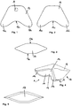
- Figures 1-3 show the blanks for the airbag cover of a front passenger airbag.
- This shows the FIG. 1 a lower blank 12, the FIG. 2 an upper blank 16 and the FIG. 3 another blank 18.
- Lower blank 12 and upper blank 16 are congruent with the exception that the lower blank 12 has a gas generator opening 14.
- there is an outflow opening which, for example, can be designed as an opening in the upper blank 16 (not shown).
- Lower blank 12 and upper blank 16 each have a first forwardly projecting portion 12a, 16a and a second forwardly projecting portion 12b, 16b.
- the concave edge 12c or 16c extends between these two sections.
- the further blank 18 is essentially lenticular, ie double-convex with a lower edge 18a and an upper edge 18b.
- FIG. 4 shows the airbag cover 10 of the passenger front airbag 5 in the finished sewn expanded state.
- the FIG. 5 shows the view from direction A in FIG. 4 .
- the further blank 18 is virtually identical to the baffle 11 and that the baffle has a concave shape such that when mounted a left and a right section 11b, 11c extend further into the interior of the motor vehicle than a central section 11a of the baffle 11.
- the baffle in the middle has its maximum height.
- Upper and lower blank 12, 16 form the side surfaces of the airbag cover.
- FIGS. 6 and 7 show an airbag cover 10, as just described as mounted on the instrument panel of a motor vehicle front passenger bag 5 in a fully expanded state. It can be seen that the lower blank 12 partially rests on the surface of the instrument panel 20 and that the airbag cover 10 extends from here into the interior of the motor vehicle in the direction of the occupant I.
- the baffle 11 of the expanded airbag shell is positioned completely above the instrument panel and thus also assigned exclusively to the head of the occupant I.
- a safety belt 30 which has a shoulder portion 32 and a pelvic portion 34.
- Shoulder portion 32 and pelvic portion 34 are separated by a belt tongue 36.
- This belt tongue is preferably designed so that it blocks when exceeding a predetermined tensile force in the webbing and thus decoupled shoulder portion and pelvic portion of the seat belt from each other.
- Such a belt tongue is for example in the EP 1 983 857 B1 , to the disclosure of which reference is hereby explicitly made.
- the length of the pelvic portion can not increase even when the Gurtkraftbegrenzung begins, so that the desired in-position holding the pelvis is still improved.
- a detection system (not shown) which detects if an occupant sitting in the passenger seat and generates a warning sound if an occupant is detected and this is not strapped.
- FIGS. 8 and 9 show that in the FIGS. 6 or 7 shown when immersing the occupant I in the airbag cover 10, namely in the baffle 11. It can be seen that the pelvis of the occupant I due to the pelvic portion 34 of the seat belt 30 is not substantially displaced, so that the upper body of the occupant I after insertion the belt force limiting substantially performs a forward tilting movement, so that the head is the foremost body part of the upper body and only this is caught by the front passenger bag 5.
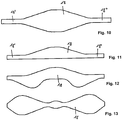
- FIGS. 10 to 13 show various alternative forms for further cutting 18. How to particular the FIGS. 10 and 11 takes, the further blank 18 side portions 18, 18 "have, which do not belong to the baffle, but which extend in the assembled and expanded state of the airbag cover substantially parallel to the vehicle longitudinal direction and thus form part of the side surfaces of the airbag cover.
- FIGS. 12 and 13 if one deduces that the further cut can be strongly contoured, whereby in particular a good adaptation to the surface shape of the instrument panel can be achieved.
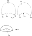
- FIGS. 14a to 14e show a second embodiment of a gas bag envelope based on their manufacturing process.
- This airbag cover also consists of three blanks ( Fig. 14a ), wherein two blanks 41, 42 are congruent, but not upper and lower, but rather left and right blanks.
- the two blanks 41, 42 are congruently formed in a kind of horseshoe shape and each have a recess.
- the third blank 43 is round in the embodiment shown.
- first blanks 41, 42 are placed against each other such that the indentations form a circular recess; In this case, the first blank 41 overlaps the second blank 42 in sections.
- Hidden lines are shown in dashed lines.
- the first two blanks are connected to each other by means of the first seams 45.
- These first seams shown in dash-dot form are shear seams ( Fig. 14b ).
- the circular recess is closed by means of the third blank 43, for which purpose it is sewn by means of the second seam 46.
- This seam is also a shear seam and shown in dotted lines. However, it is also possible to form this seam as a shaved seam ( Fig. 14c ).
- the resulting work piece is moved along in the FIG. 14c shown fold lines 49 (dotted darg Hor) folded ( Fig. 14d ) and by means of the third, designed as a shaved seam 47 (shown with the pattern dot-dot-dash) at the edge closed ( Fig. 14e ).
- the Figure 14e is a view from above.
- FIGS. 15 and 16 show a third embodiment of an airbag cover.
- This consists of two blanks, which are referred to as fourth and fifth blanks 51, 52 and, as in the first embodiment, upper and lower blanks.
- the blanks are not congruent, but the respective front edge 51c, 52c, is concave at the fourth blank 51 and wavy at the fifth blank 52.
- These two blanks also have forwardly projecting portions 51a, 51b; 52a, 52b.
- the two blanks are connected around, for example sewn.
Landscapes
- Engineering & Computer Science (AREA)
- Mechanical Engineering (AREA)
- Automation & Control Theory (AREA)
- Air Bags (AREA)
Description
- Die Erfindung betrifft einen Beifahrer-Frontgassack nach dem Oberbegriff des Anspruchs 1 sowie ein Fahrzeug mit einem solchen Beifahrer-Frontgassack nach Anspruch 10.
- Sogenannte Beifahrer-Frontgassäcke sind im Automobilbau weit verbreitet und dienen dem Schutz des Beifahrers, nämlich insbesondere dem Schutz seines Kopfes, beim einem Frontalzusammenstoß oder einem seitlich versetzten Frontalzusammenstoß. Ein solcher Beifahrer-Frontgassack ist in der Instrumententafel - meist in einem oberen Bereich - angeordnet und entfaltet sich bei Detektion eines Frontalaufpralls zwischen Instrumententafel/Windschutzscheibe und Insassen.
- Die Gassackhüllen bisheriger Beifahrer-Frontgassäcke, wie z.B. in der
EP 1 693 256 beschrieben, sind sehr großvolumig ausgelegt und decken hierbei den gesamten vor dem Beifahrer liegenden oberen Bereich der Instrumententafel ab. Hierdurch bieten sie sehr guten Schutz, da sowohl Kopf als auch Thoraxbereich vom Beifahrer-Frontgassack aufgefangen werden können. Neben diesem Vorteil, die ein großvolumiger Beifahrer-Frontgassack bietet, ergeben sich jedoch auch zahlreiche Nachteile: Aufgrund des großen Volumens muss ein entsprechend großer und starker Gasgenerator eingesetzt werden, was zunächst ein relativ hohes Gewicht bedeutet, was natürlich stets unerwünscht ist. Weiterhin müssen sich großvolumige Beifahrer-Frontgassäcke sehr schnell entfalten um rechtzeitig ihren vollständigen Entfaltungszustand zu erreichen. Hierdurch kann der Beifahrer-Frontgassack selbst zu einer Gefahr für den Beifahrer werden, wenn sich dieser nicht in seiner Standard-Sitzposition befindet. - Es wird ein großer Aufwand betrieben, um dieses Problem zu lösen, wie die hierzu veröffentlichte sehr umfangreiche Patentliteratur zeigt.
- Hiervon ausgehend stellt sich die vorliegende Erfindung die Aufgabe, einen Beifahrer-Frontgassack dahingehend weiterzubilden, dass die eben beschriebenen Nachteile behoben oder zumindest abgemildert werden.
- Diese Aufgabe wird durch einen Beifahrer-Frontgassack mit den Merkmalen des Anspruchs 1 gelöst. Ein Kraftfahrzeug mit einem solchen Beifahrer-Frontgassack ist in Anspruch 10 angegeben.
- Es hat sich durch Versuche herausgestellt, dass bei einem angegurteten Beifahrer derjenige Teil der Gassackhülle des Beifahrer-Frontgassackes, welcher dem Thoraxbereich zugeordnet ist, in vielen Fahrzeuggeometrien eine sehr viel kleinere Bedeutung für den Insassenschutz hat als derjenige Teil der Gassackhülle, welcher dem Kopfbereich oder dem Kopf-Schulterbereich zugeordnet ist. Dies liegt darin begründet, dass der Beckenabschnitt des angelegten Sicherheitsgurtes das Becken nahezu in seiner Ausgangsstellung hält, so dass die Bewegung des Oberkörpers des Beifahrers im Falle eines Frontalaufpralls nach Einsetzen der Gurtkraftbegrenzung im Wesentlichen eine Kippbewegung um das Becken ist. Die Oberkörper-Rückhaltefunktion kann durch die Auslegung des Kraftbegrenzers erreicht werden. Aufgrund der Tatsache, dass die Oberfläche der Instrumententafel vom Kopf-Brust-Bereich des Insassen relativ weit entfernt ist, ist der Beitrag der Rückhaltewirkung, welcher der Beifahrer-Frontgassack für den Thoraxbereich auch bei einsetzender Gurtkraftbegrenzung zur Verfügung stellt, oft gering.
- In vielen Ländern, insbesondere in Europa, ist die Anschnallquote auch der Beifahrer inzwischen so hoch, dass man bei Auslegung des Beifahrergassacks von einem angeschnallten Beifahrer ausgehen kann.
- Erfindungsgemäß ist die Prallfläche der Gassackhülle deshalb ausschließlich dem Kopfbereich oder dem Kopf- und Schulterbereich des Beifahrers zugeordnet. Somit kann die Gassackhülle des Beifahrer-Frontgassackes so ausgebildet sein, dass sie nur ein relativ kleines Volumen, vorzugsweise nämlich maximal 50 Liter, insbesondere vorzugsweise 35 bis 50 Liter einschließt. In speziellen Anwendungs- und Anforderungsfällen kann auch ein etwas größeres Gassackvolumen um 60 Liter notwendig sein. Dieses etwas größere Volumen (welches aber immer noch kleiner ist als das eines Standard-Beifahrer-Gassacks) kann insbesondere in folgenden Fällen notwendig sein: Zum einen, wenn das Gassackmodul im obersten Bereich der Instrumententafel nahe der Windschutzscheibe angeordnet ist (sogenannter "top mount") und zum anderen, wenn der Frontgassack ein sehr hohes Maß an Seitenschutz bei einem seitlich versetzen Frontalzusammenstoß bieten soll. Um dennoch auch bei einem seitlich versetzten Frontalzusammenstoß einen guten Schutz zu bieten, weist die Prallfläche der Gassackhülle des Beifahrer-Frontgassackes im vollständig expandierten Zustand eine konkave Form derart auf, dass sich ein linker und ein rechter Abschnitt der Prallfläche jeweils weiter in den Innenraum des Kraftfahrzeugs erstrecken als ein mittlerer Abschnitt.
- Durch das kleine Gassackvolumen ergibt sich eine erhebliche Gewichtsreduzierung und die Gefährdung eines sich außerhalb seiner Standard-Sitzposition befindenden Beifahrers wird deutlich reduziert.
- Wie bereits erwähnt, bietet der erfindungsgemäße Beifahrer-Frontgassack nur einem angegurteten Beifahrer idealen Schutz. Aufgrund der Tatsache, das in vielen Ländern, beispielsweise in Deutschland, die Anschnallquote sehr hoch ist, können die Vorteile, welche der erfindungsgemäße Beifahrer-Frontgassack insbesondere in Bezug auf out-of-position Situationen bietet, die Nachteile in Bezug auf Unfälle mit nicht angeschnalltem Insassen statistisch überwiegen.
- Um Unfallsituationen mit einem nicht angeschnallten Beifahrer praktisch ganz auszuschließen, ist es zu bevorzugen, wenn der erfindungsgemäße Beifahrer-Frontgassack nur bei Kraftfahrzeugen mit einem Warnsystem für einen nicht angegurteten Beifahrer eingebaut wird. Solche Warnsysteme sind bekannt und erzeugen bei nicht angeschnalltem Beifahrer ein akustisches Warnsignal.
- Bevorzugte Ausführungsformen, insbesondere hinsichtlich der schnitttechnischen Ausgestaltung der Gassackhülle, sind in den Ansprüchen 3 bis 7 angegeben.
- Die Erfindung wird nun anhand eines Ausführungsbeispiels mit Bezug auf die Figuren 1 bis 13 näher erläutert. Hierbei zeigen:
-
- Figur 1
- Einen unteren Zuschnitt,
- Figur 2
- einen oberen Zuschnitt,
- Figur 3
- einen weiteren Zuschnitt,
- Figur 4
- eine Gassackhülle, die aus den in den
Figuren 1 bis 3 gezeigten Zuschnitten zusammengesetzt ist, in einem vollständig expandierten Zustand, - Figur 5
- die Gassackhülle aus
Figur 4 in einer Draufsicht aus Richtung A, - Figur 6
- einen schematisierten Schnitt durch einen vorderen Bereich eines Kraftfahrzeugs mit einem Beifahrer-Frontgassack, dessen Gassackhülle im vollständig expandierten Zustand dargestellt ist,
- Figur 7
- das in
Figur 6 Gezeigte in einer Draufsicht aus Richtung B, jedoch ohne Fahrzeugsitz und Sicherheitsgurt, - Figur 8
- das in
Figur 6 Gezeigte beim Eintauchen des Insassen in die Gassackhülle des Frontgassacks, - Figur 9
- das in
Figur 8 Gezeigte in einer derFigur 4 entsprechenden Darstellung, - Figur 9a
- das in
Figur 9 Gezeigte im Falle eines seitlich versetzten Frontalzusammenstoßes, - Figuren 10 bis 13
- alternative Ausführungsformen des weiteren Zuschnitts,
- Figuren 14a bis 14e
- den Herstellungsprozess einer zweite Ausführungsform einer Gassackhülle,
- Figur 15
- zwei Zuschnitte für eine dritte Ausführungsform einer Gassackhülle und
- Figur 16
- die aus den beiden Zuschnitten der
Figur 15 bestehende Gassackhülle im expandierten Zustand. -
Figuren 1-3 zeigen die Zuschnitte für die Gassackhülle eines Beifahrer-Frontgassacks. Hierbei zeigt dieFigur 1 einen unteren Zuschnitt 12, dieFigur 2 einen oberen Zuschnitt 16 und dieFigur 3 einen weiteren Zuschnitt 18. Unterer Zuschnitt 12 und oberer Zuschnitt 16 sind deckungsgleich mit der Ausnahme, dass der untere Zuschnitt 12 eine Gasgeneratoröffnung 14 aufweist. In der Regel ist eine Ausströmöffnung vorhanden, welche beispielsweise als Öffnung im oberen Zuschnitt 16 ausgestaltet sein kann (nicht dargestellt). Unterer Zuschnitt 12 und oberer Zuschnitt 16 weisen jeweils einen ersten nach vorne ragenden Abschnitt 12a, 16a und einen zweiten nach vorne ragenden Abschnitt 12b, 16b auf. Zwischen diesen beiden Abschnitten erstreckt sich jeweils die konkave Kante 12c beziehungsweise 16c. Der weitere Zuschnitt 18 ist im Wesentlichen linsenförmig, also doppel-konvex mit einer unteren Kante 18a und einer oberen Kante 18b. - Das Zusammennähen der eben beschriebenen drei Zuschnitte erfolgt derart, dass die untere Kante 18a des weiteren Zuschnitts 18 mit der konkaven Kante 12c des unteren Zuschnitts 12 und die obere Kante 18b des weiteren Zuschnitts 18 mit der konkaven Kante 16c des oberen Zuschnitts 16 vernäht wird. Die verbleibenden Kantenabschnitte des unteren Zuschnitts 12 und des oberen Zuschnitts 16 werden miteinander vernäht, so dass die Gassackhülle 10 geschlossen ist und einen Gasraum umgibt. Anstatt Nähen können natürlich auch andere Verbindungstechniken, wie insbesondere Schweißen oder Kleben angewendet werden.
- Die
Figur 4 zeigt die Gassackhülle 10 des Beifahrer-Frontgassackes 5 im fertig vernähten expandierten Zustand. DieFigur 5 zeigt die Ansicht aus Richtung A inFigur 4 . Man sieht, dass der weitere Zuschnitt 18 praktisch identisch mit der Prallfläche 11 ist und dass die Prallfläche eine konkave Form derart aufweist, dass sich im montierten Zustand ein linker und ein rechter Abschnitt 11b, 11c weiter in den Innenraum des Kraftfahrzeugs erstrecken als ein mittlerer Abschnitt 11a der Prallfläche 11. Man erkennt weiterhin, dass aufgrund der Linsenform des weiteren Zuschnittes 18 die Prallfläche in der Mitte ihre maximale Höhe aufweist. Oberer und unterer Zuschnitt 12, 16 bilden die Seitenflächen der Gassackhülle. - Die
Figuren 6 und 7 zeigen eine Gassackhülle 10, wie sie eben beschrieben wurde als an der Instrumententafel eines Kraftfahrzeugs montierten Beifahrer-Frontgassack 5 in vollständig expandiertem Zustand. Man sieht, dass der untere Zuschnitt 12 abschnittsweise auf der Oberfläche der Instrumententafel 20 aufliegt und dass sich die Gassackhülle 10 von hier aus ins Innere des Kraftfahrzeugs in Richtung des Insassen I erstreckt. Hierbei ist die Prallfläche 11 der expandierten Gassackhülle vollständig oberhalb der Instrumententafel positioniert und somit auch ausschließlich dem Kopf des Insassen I zugeordnet. - Wie man der
Figur 6 entnimmt, befindet sich der zu schützende Insasse in einem angeschnallten Zustand, nämlich mittels eines Sicherheitsgurtes 30 welcher einen Schulterabschnitt 32 und einen Beckenabschnitt 34 aufweist. Schulterabschnitt 32 und Beckenabschnitt 34 sind durch eine Gurtzunge 36 voneinander getrennt. Diese Gurtzunge ist vorzugsweise so ausgebildet, dass sie bei Überschreiten einer vorbestimmten Zugkraft im Gurtband blockiert und somit Schulterabschnitt und Beckenabschnitt des Sicherheitsgurtes voneinander entkoppelt. Eine solche Gurtzunge ist beispielsweise in derEP 1 983 857 B1 beschrieben, auf deren Offenbarungsgehalt hiermit explizit verwiesen wird. Hierdurch kann sich die Länge des Beckenabschnitts auch bei einsetzender Gurtkraftbegrenzung nicht erhöhen, so dass das gewünschte In-Position-Halten des Beckens noch verbessert wird. - Um sicherzustellen, dass der Insasse angeschnallt ist, ist vorzugsweise ein Erkennungssystem (nicht dargestellt) vorhanden, welches erkennt, ob ein Insasse auf dem Beifahrersitz sitzt und einen Warnton erzeugt, falls ein Insasse erkannt wird und dieser nicht angeschnallt ist.
- Die
Figuren 8 und 9 zeigen das in denFiguren 6 beziehungsweise 7 Gezeigte bei Eintauchen des Insassen I in die Gassackhülle 10, nämlich in die Prallfläche 11. Man sieht, dass sich das Becken des Insassen I aufgrund des Beckenabschnittes 34 des Sicherheitsgurtes 30 im Wesentlichen nicht verschiebt, so dass der Oberkörper des Insassen I nach Einsetzen der Gurtkraftbegrenzung im Wesentlichen eine nach vorne gehende Kippbewegung durchführt, so dass der Kopf das vorderste Körperteil des Oberkörpers ist und nur dieser vom Beifahrer-Frontgassack 5 aufgefangen wird. - Aufgrund der konkaven Form der Prallfläche 11 wird der Kopf des Insassen auch dann sicher aufgefangen, wenn er aufgrund eines seitlich versetzten Aufpralles nicht exakt auf die Mitte der Prallfläche auftrifft, wie dies in
Figur 9a zu sehen ist. - Die
Figuren 10 bis 13 zeigen verschiedene alternative Formen für den weiteren Zuschnitt 18. Wie man insbesondere denFiguren 10 und 11 entnimmt, kann der weitere Zuschnitt 18 Seitenbereiche 18, 18" aufweisen, welche nicht zur Prallfläche gehören, sondern welche sich im montierten und expandierten Zustand der Gassackhülle im wesentlichen parallel zur Fahrzeuglängsrichtung erstrecken und somit einen Teil der Seitenflächen der Gassackhülle bilden. - Den
Figuren 12 und 13 entnimmt man, dass der weitere Zuschnitt stark konturiert sein kann, wodurch insbesondere eine gute Anpassung an die Oberflächenform der Instrumententafel erreicht werden kann. - Die
Figuren 14a bis 14e zeigen eine zweite Ausführungsform einer Gassackhülle anhand ihres Herstellungsprozesses. Auch diese Gassackhülle besteht aus drei Zuschnitten (Fig. 14a ), wobei zwei Zuschnitte 41, 42 deckungsgleich sind, jedoch nicht obere und untere, sondern eher linke und rechte Zuschnitte sind. Die beiden Zuschnitte 41, 42 sind deckungsgleich in einer Art Hufeisenform ausgebildet und weisen jeweils eine Einbuchtung auf. Der dritte Zuschnitt 43 ist im gezeigten Ausführungsbeispiel rund. - Zunächst werden die beiden ersten Zuschnitte 41, 42 derart aneinander gelegt, dass die Einbuchtungen eine kreisförmige Ausnehmung bilden; hierbei überlappt der erste Zuschnitt 41 den zweiten Zuschnitt 42 abschnittsweise. Verdeckte Linien sind gestrichelt dargestellt. In diesem Zustand werden die beiden ersten Zuschnitte mittels der ersten Nähte 45 miteinander verbunden. Diese gestrichpunktet dargestellten ersten Nähte sind Schernähte (
Fig. 14b ). - Nun wird die kreisförmige Ausnehmung mittels des dritten Zuschnitts 43 verschlossen, wozu dieser mittels der zweiten Naht 46 angenäht wird. Diese Naht ist ebenfalls eine Schernaht und gestrichpunktet dargestellt. Es ist jedoch auch möglich, diese Naht als Schälnaht auszubilden (
Fig. 14c ). - Das nun entstandene Werkstück wird entlang der in der
Figur 14c gezeigten Faltlinien 49 (gepunktet dargstellt) gefaltet (Fig. 14d ) und mittels der dritten, als Schälnaht ausgebildeten Naht 47 (mit dem Muster Punkt-Punkt-Strich dargestellt) randseitig geschlossen (Fig. 14e ). Hierdurch erhält die Prallfläche 11 die gewünschte konkave Form mit linkem Abschnitt 11b, rechtem Abschnitt 11c und mittlerem Abschnitt 11a. DieFigur 14e ist eine Ansicht von oben. - Die
Figuren 15 und 16 zeigen eine dritte Ausführungsform einer Gassackhülle. Diese besteht aus zwei Zuschnitten, welche als vierte und fünfte Zuschnitte 51, 52 bezeichnet sind und, ähnlich wie in der ersten Ausführungsform, obere und untere Zuschnitte sind. Die Zuschnitte sind nicht deckungsgleich, sondern die jeweils vordere Kante 51c, 52c, ist beim vierten Zuschnitt 51 konkav und beim fünften Zuschnitt 52 gewellt. Auch diese beiden Zuschnitte weisen nach vorne ragende Abschnitte 51a, 51b; 52a, 52b auf. Die beiden Zuschnitte werden ringsum verbunden, beispielsweise vernäht. Im expandieretn Zustand, wie er inFigur 16 angedeutet ist, ergibt sich eine konkave Prallfläche 11. -
- 5
- Beifahrer-Frontgassack
- 10
- Gassackhülle
- 11
- Prallfläche
- 11a
- mittlerer Abschnitt
- 11b
- linker Abschnitt
- 11c
- rechter Abschnitt
- 12
- unterer Zuschnitt
- 12a
- erster nach vorne ragender Abschnitt
- 12b
- zweiter nach vorne ragender Abschnitt
- 12c
- konkave Kante
- 14
- Gasgeneratoröffnung
- 16
- oberer Zuschnitt
- 16a
- erster nach vorne ragender Abschnitt
- 16b
- zweiter nach vorne ragender Abschnitt
- 16c
- konkave Kante
- 18
- weiterer Zuschnitt
- 18a
- untere Kante
- 18b
- obere Kante
- 20
- Instrumententafel
- 22
- Windschutzscheibe
- 25
- Fahrzeugsitz
- 30
- Sicherheitsgurt
- 32
- Schulterabschnitt
- 34
- Beckenabschnitt
- 36
- Gurtzunge
- 41
- erster Zuschnitt
- 42
- zweiter Zuschnitt
- 43
- dritter Zuschnitt
- 45
- erste Naht
- 46
- zweite Naht
- 47
- dritte Naht
- 49
- Faltlinie
- 51
- vierter Zuschnitt
- 51a
- erster nach vorne ragender Abschnitt
- 51b
- zweiter nach vorne ragender Abschnitt
- 51c
- vordere Kante
- 52
- fünfter Zuschnitt
- 52a
- erster nach vorne ragender Abschnitt
- 52b
- zweiter nach vorne ragender Abschnitt
- 52c
- vordere Kante
- I
- Insasse
Claims (11)
- Beifahrer-Frontgassack (5) zur Anordnung in der Instrumententafel (20) eines Kraftfahrzeugs,
mit einer Gassackhülle (10), welche eine Prallfläche (11) und sich von der Prallfläche (11) erstreckende Seitenflächen aufweist, wobei die Prallfläche (11) bei vollständig expandierter, von äußeren Kräften freier Gassackhülle (10) eine konkave Form derart aufweist, dass sich ein linker und ein rechter Abschnitt (11b, 11c) der Prallfläche (11) jeweils weiter in den Innenraum des Kraftfahrzeugs erstrecken als ein mittlerer Abschnitt (11a),
dadurch gekennzeichnet, dass die Prallfläche (11) ausschließlich dem Kopfbereich oder dem Kopf- und Schulterbereich des Beifahrers (I) zugeordnet ist und dass die vollständig expandierte Gassackhülle (10) ein Volumen von maximal 60 Liter umschließt. - Beifahrer-Frontgassack nach Anspruch 1, dadurch gekennzeichnet, dass die vollständig expandierte Gassackhülle (10) ein Volumen von 35 bis 50 Liter umschließt.
- Beifahrer-Frontgassack nach einem der vorangehenden Ansprüche, dadurch gekennzeichnet, dass die Seitenflächen wenigstens einen oberen und einen unteren Zuschnitt (12, 16) aufweisen, wobei wenigstens einer dieser beiden Zuschnitte (12, 16) jeweils eine konkave Kante (12c, 16c) aufweisen, welche der Prallfläche (11) ihre konkave Form geben.
- Beifahrer-Frontgassack nach Anspruch 3, dadurch gekennzeichnet, dass die Prallfläche (11) ein weiterer Zuschnitt (18) oder ein Teil eines weiteren Zuschnitts (18) ist, welcher zwischen oberem und unterem Zuschnitt (12, 16) gehalten ist.
- Beifahrer-Frontgassack nach Anspruch 4, dadurch gekenzeichnet, dass der weitere Zuschnitt (18) eine nicht konstante Höhe aufweist.
- Beifahrer-Frontgassack nach Anspruch 5, dadurch gekennzeichnet, dass der weitere Zuschnitt (18) im Bereich des mittleren Abschnitts der Prallfläche seine maximale Höhe aufweist.
- Beifahrer-Frontgassack nach einem der Ansprüche 3 bis 6, dadurch gekennzeichnet, dass der untere Zuschnitt (12) bei vollständig expandierter Gassackhülle zumindest abschnittsweise auf der Instrumententafel (20) aufliegt.
- Beifahrer-Frontgassack nach einem der Ansprüche 2 bis 7, dadurch gekennzeichnet, dass der untere Zuschnitt eine Öffnung (Gasgeneratoröffnung 14) für einen Inflator aufweist.
- Kraftfahrzeug mit einem Beifahrer-Frontgassack nach einem der vorangehenden Ansprüche mit
genau einem Beifahrer-Frontgassack (5), wobei dieser Beifahrer-Frontgassack eine Gassackhülle (10) aufweist, welche eine Prallfläche (11) und sich von der Prallfläche (11) erstreckende Seitenflächen aufweist, wobei die Prallfläche (11) ausschließlich dem Kopfbereich oder dem Kopf- und Schulterbereich des Beifahrers (I) zugeordnet ist und wobei die Prallfläche (11) bei vollständig expandierter, von äußeren Kräften freier Gassackhülle (10) eine konkave Form derart aufweist, dass sich ein linker und ein rechter Abschnitt (11b, 11c) der Prallfläche (11) jeweils weiter in den Innenraum des Kraftfahrzeugs erstrecken als ein mittlerer Abschnitt (11a) und einem Sicherheitsgurtsystem für den Beifahrer,
wobei sich bei vollständig expandierter Gassackhülle (10) die Prallfläche (11) vollständig oberhalb der Instrumententafel (20) befindet. - Kraftfahrzeug nach Anspruch 9, dadurch gekennzeichnet, dass es ein Erkennungssystem für einen nicht angeschnallten Beifahrer aufweiset, welches bei Erkennen eines nicht angeschnallten Beifahrers ein Warnsignal erzeugt.
- Kraftfahrzeug nach einem der Ansprüche 9 oder 10, dadurch gekennzeichnet, dass die Gurtzunge des Sicherheitsgurtsystems den Beckenabschnitt (34) und den Schulterabschnitt (32) des Sicherheitsgurtes (30) bei Überschreiten einer vorbestimmten Grenzkraft im Sicherheitsgurt voneinander entkoppelt.
Applications Claiming Priority (2)
| Application Number | Priority Date | Filing Date | Title |
|---|---|---|---|
| DE102009040118A DE102009040118A1 (de) | 2009-09-04 | 2009-09-04 | Beifahrer-Frontgassack und Kraftfahrzeug |
| PCT/EP2010/005382 WO2011026617A1 (de) | 2009-09-04 | 2010-09-02 | Beifahrer-frontgassack |
Publications (2)
| Publication Number | Publication Date |
|---|---|
| EP2473381A1 EP2473381A1 (de) | 2012-07-11 |
| EP2473381B1 true EP2473381B1 (de) | 2017-12-27 |
Family
ID=43242905
Family Applications (1)
| Application Number | Title | Priority Date | Filing Date |
|---|---|---|---|
| EP10754275.5A Active EP2473381B1 (de) | 2009-09-04 | 2010-09-02 | Beifahrer-frontgassack |
Country Status (9)
| Country | Link |
|---|---|
| US (1) | US8544882B2 (de) |
| EP (1) | EP2473381B1 (de) |
| JP (1) | JP2013503771A (de) |
| KR (1) | KR101443128B1 (de) |
| CN (1) | CN102481888A (de) |
| BR (1) | BR112012004924B1 (de) |
| DE (1) | DE102009040118A1 (de) |
| RU (1) | RU2518132C2 (de) |
| WO (1) | WO2011026617A1 (de) |
Families Citing this family (21)
| Publication number | Priority date | Publication date | Assignee | Title |
|---|---|---|---|---|
| DE102012007408B4 (de) | 2012-04-16 | 2023-08-03 | Autoliv Development Ab | Beifahrer-Frontgassack und Kraftfahrzeug mit einem solchen Beifahrer-Frontgassack |
| US8608199B2 (en) * | 2012-04-26 | 2013-12-17 | Trw Vehicle Safety Systems Inc. | Air bag with conical portion |
| JP6224915B2 (ja) * | 2013-05-20 | 2017-11-01 | タカタ株式会社 | エアバッグ及びエアバッグ装置 |
| US9162645B2 (en) | 2013-12-20 | 2015-10-20 | Ford Global Technologies, Llc | High pressure airbag for oblique impact modes |
| CN103802780B (zh) * | 2014-03-05 | 2016-01-27 | 延锋百利得(上海)汽车安全系统有限公司 | 一种安装于仪表板的安全气囊装置 |
| US10166946B2 (en) * | 2014-03-31 | 2019-01-01 | Autoliv Development Ab | Vehicular airbag device |
| US9561774B2 (en) | 2014-04-24 | 2017-02-07 | Ford Global Technologies, Llc | Winged driver airbag |
| US9969349B2 (en) | 2014-04-24 | 2018-05-15 | Ford Global Technologies, Llc | Passenger airbag with extended base |
| US9713998B2 (en) * | 2014-04-24 | 2017-07-25 | Ford Global Technologies, Llc | Corrugated passenger airbag |
| JP6409038B2 (ja) | 2016-09-30 | 2018-10-17 | 株式会社Subaru | 車両の乗員保護装置 |
| DE202016107171U1 (de) * | 2016-12-20 | 2018-03-21 | Dalphi Metal Espana, S.A. | Frontgassack |
| JP6750554B2 (ja) * | 2017-04-14 | 2020-09-02 | トヨタ自動車株式会社 | 助手席用エアバッグ装置及びエアバッグの折り畳み方法 |
| WO2018204429A1 (en) * | 2017-05-04 | 2018-11-08 | Trw Vehicle Safety Systems Inc. | Airbag with conical portion |
| US10814823B2 (en) | 2017-08-29 | 2020-10-27 | Ford Global Technologies, Llc | Vehicle energy absorber |
| KR20190101540A (ko) | 2018-02-23 | 2019-09-02 | 현대자동차주식회사 | 차량용 에어백 장치 |
| CN110871765B (zh) * | 2018-08-31 | 2022-08-30 | 奥托立夫开发公司 | 气囊装置 |
| CN112706719B (zh) * | 2019-10-25 | 2024-04-09 | 奥托立夫开发公司 | 安全气囊和车辆 |
| KR102898825B1 (ko) | 2019-12-13 | 2025-12-10 | 현대모비스 주식회사 | 차량용 에어백 장치 |
| KR102898820B1 (ko) | 2020-10-23 | 2025-12-10 | 현대모비스 주식회사 | 차량용 에어백 장치 |
| JP7736494B2 (ja) * | 2021-09-15 | 2025-09-09 | 株式会社Subaru | 車両用エアバッグ装置 |
| KR20240071137A (ko) | 2022-11-15 | 2024-05-22 | 현대모비스 주식회사 | 모빌리티용 에어백 장치 |
Family Cites Families (26)
| Publication number | Priority date | Publication date | Assignee | Title |
|---|---|---|---|---|
| SU1359177A1 (ru) * | 1986-04-21 | 1987-12-15 | Предприятие П/Я В-2725 | Гибка оградительна оболочка дл пользователей транспортным средством |
| DE3828072A1 (de) * | 1988-04-21 | 1989-11-02 | Ernst Hans Hellmut | Dreipunktsicherheitsgurt fuer kraftfahrzeuge |
| JPH0651458B2 (ja) * | 1989-10-23 | 1994-07-06 | 池田物産株式会社 | エアバッグ装置 |
| US5044663A (en) * | 1990-02-12 | 1991-09-03 | Solvay Automotive, Inc. | Blow molded airbag with fabric reinforcements |
| JPH0456655A (ja) * | 1990-06-27 | 1992-02-24 | Takata Kk | エアバッグ |
| US5626359A (en) * | 1993-12-02 | 1997-05-06 | Trw Vehicle Safety Systems, Inc. | Method and apparatus for controlling an actuatable restraining device in response to discrete control zones |
| US5529340A (en) * | 1995-08-14 | 1996-06-25 | Morton International, Inc. | Single piece pattern air bag |
| JP3035691U (ja) | 1996-09-12 | 1997-03-28 | 桂司 古川 | 自動車用エアーバッグ |
| US5975571A (en) * | 1997-07-17 | 1999-11-02 | Breed Automotive Technology, Inc. | Single piece air bag with improved stress distribution |
| US6019390A (en) * | 1998-04-30 | 2000-02-01 | Milliken & Company | Multiple panel airbag |
| JP3772548B2 (ja) * | 1998-09-11 | 2006-05-10 | タカタ株式会社 | エアバッグ装置 |
| DE19844427A1 (de) * | 1998-09-28 | 2000-04-06 | Oskar Bschorr | Reduzierung der Knallbelastung beim Auslösen eines Airbags |
| JP4608072B2 (ja) * | 2000-02-25 | 2011-01-05 | タカタ株式会社 | エアバッグ装置 |
| JP2002046562A (ja) * | 2000-08-04 | 2002-02-12 | Takata Corp | エアバッグ |
| US6672618B2 (en) * | 2000-10-17 | 2004-01-06 | Milliken & Company | Multiple panel airbag and method |
| KR100551297B1 (ko) * | 2003-07-04 | 2006-02-10 | 현대자동차주식회사 | 시트 벨트 경고 기능을 갖는 에어백 시스템 |
| US20050098994A1 (en) * | 2003-11-07 | 2005-05-12 | Takata Corporation | Airbag cushion with angled recess |
| US20060103118A1 (en) * | 2004-02-05 | 2006-05-18 | Takata Corporation | Twin airbag |
| JP2006232267A (ja) | 2005-02-22 | 2006-09-07 | Takata Corp | エアバッグクッション |
| US7475905B2 (en) * | 2005-03-31 | 2009-01-13 | Tk Holdings Inc. | Airbag module |
| JP4235975B2 (ja) * | 2005-06-10 | 2009-03-11 | オートリブ ディベロップメント エービー | エアバッグ装置及び、エアバッグの製造方法 |
| JP2007008219A (ja) * | 2005-06-28 | 2007-01-18 | Takata Corp | 乗員拘束装置 |
| DE102006005886B4 (de) * | 2006-02-09 | 2007-11-08 | Autoliv Development Ab | Gurtzunge für einen Sicherheitsgurt |
| JP5076408B2 (ja) * | 2006-09-05 | 2012-11-21 | タカタ株式会社 | エアバッグ、エアバッグ装置及び車両 |
| DE102007029650A1 (de) * | 2007-06-26 | 2009-01-08 | Volkswagen Ag | Vorrichtung zur Abfrage eines Fahrzeugsitz-Status |
| JP5016429B2 (ja) * | 2007-09-25 | 2012-09-05 | 日本プラスト株式会社 | エアバッグおよびエアバッグの製造方法 |
-
2009
- 2009-09-04 DE DE102009040118A patent/DE102009040118A1/de not_active Withdrawn
-
2010
- 2010-09-02 WO PCT/EP2010/005382 patent/WO2011026617A1/de not_active Ceased
- 2010-09-02 KR KR1020127005457A patent/KR101443128B1/ko active Active
- 2010-09-02 BR BR112012004924-0A patent/BR112012004924B1/pt active IP Right Grant
- 2010-09-02 US US13/393,252 patent/US8544882B2/en not_active Expired - Fee Related
- 2010-09-02 JP JP2012527234A patent/JP2013503771A/ja active Pending
- 2010-09-02 RU RU2012112876/11A patent/RU2518132C2/ru active
- 2010-09-02 CN CN201080039327XA patent/CN102481888A/zh active Pending
- 2010-09-02 EP EP10754275.5A patent/EP2473381B1/de active Active
Also Published As
| Publication number | Publication date |
|---|---|
| KR20120093832A (ko) | 2012-08-23 |
| BR112012004924B1 (pt) | 2019-04-09 |
| KR101443128B1 (ko) | 2014-09-22 |
| US20120205899A1 (en) | 2012-08-16 |
| DE102009040118A1 (de) | 2011-03-10 |
| EP2473381A1 (de) | 2012-07-11 |
| JP2013503771A (ja) | 2013-02-04 |
| RU2518132C2 (ru) | 2014-06-10 |
| RU2012112876A (ru) | 2013-10-10 |
| CN102481888A (zh) | 2012-05-30 |
| BR112012004924A2 (pt) | 2016-04-05 |
| WO2011026617A1 (de) | 2011-03-10 |
| US8544882B2 (en) | 2013-10-01 |
Similar Documents
| Publication | Publication Date | Title |
|---|---|---|
| EP2473381B1 (de) | Beifahrer-frontgassack | |
| DE102011051318B4 (de) | Interne airbag-vorrichtung | |
| DE4304919B4 (de) | Airbag-Vorrichtung im Bereich eines Dachrahmens eines Fahrzeugs | |
| EP1568544B2 (de) | Seitenaufprall-Rückhaltevorrichtung | |
| DE602005002099T2 (de) | Luftsack | |
| WO2019166268A1 (de) | Gassackmodul sowie fahrzeuginsassen-rückhaltesystem | |
| DE102010056342A1 (de) | Vorhanggassack für ein Fahrzeug | |
| DE102010019592A1 (de) | Beifahrer-Frontgassack-Einrichtung zum Einbau in das Armaturenbrett eines Kraftfahrzeugs | |
| DE112017000630T5 (de) | Sicherheits-Airbag | |
| DE60125745T2 (de) | Selbstzentrierender luftsack und herstellungsverfahren | |
| DE102017103826A1 (de) | Fahrzeuginsassen-Rückhaltevorrichtung und Verfahren zum Betreiben einer Fahrzeuginsassen-Rückhaltevorrichtung | |
| DE102004026313B4 (de) | Überkopf-Airbagsystem | |
| EP0592815A1 (de) | Kopfschutzvorrichtung für Insassen von Fahrzeugen | |
| DE29916526U1 (de) | Fahrzeuginsassen-Rückhaltevorrichtung | |
| EP3894272B1 (de) | Fahrzeugsitz | |
| DE102010054743A1 (de) | Sicherheitseinrichtung in einem Kraftfahrzeug | |
| EP1750977B1 (de) | Kraftfahrzeug mit einem kniegassack | |
| DE10257248A1 (de) | Kraftfahrzeug mit einer Karosseriestruktur und mit einer Seitenaufprallschutzeinrichtung | |
| EP3917809B1 (de) | Gassackmodul für ein fahrzeuginsassen-rückhaltesystem sowie verfahren zum betreiben eines fahrzeuginsassen-rückhaltesystems mit einem solchen gassackmodul | |
| DE102009016885A1 (de) | Airbagmodul und Fahrzeugsitz mit dem Airbagmodul | |
| DE29821621U1 (de) | Aufprall-Schutzvorrichtung für Kraftfahrzeuge | |
| DE102008010279A1 (de) | Fahrzeugsitz mit integriertem Airbag | |
| DE102013005387B4 (de) | Beifahrer-Frontgassack-Einrichtung | |
| DE10204486A1 (de) | Schutzeinrichtung für Insasssen von Kraftfahrzeugen | |
| DE102013021569A1 (de) | Insassenschutzvorrichtung für ein Fahrzeug und Fahrzeug |
Legal Events
| Date | Code | Title | Description |
|---|---|---|---|
| PUAI | Public reference made under article 153(3) epc to a published international application that has entered the european phase |
Free format text: ORIGINAL CODE: 0009012 |
|
| 17P | Request for examination filed |
Effective date: 20120404 |
|
| AK | Designated contracting states |
Kind code of ref document: A1 Designated state(s): AL AT BE BG CH CY CZ DE DK EE ES FI FR GB GR HR HU IE IS IT LI LT LU LV MC MK MT NL NO PL PT RO SE SI SK SM TR |
|
| DAX | Request for extension of the european patent (deleted) | ||
| GRAP | Despatch of communication of intention to grant a patent |
Free format text: ORIGINAL CODE: EPIDOSNIGR1 |
|
| STAA | Information on the status of an ep patent application or granted ep patent |
Free format text: STATUS: GRANT OF PATENT IS INTENDED |
|
| INTG | Intention to grant announced |
Effective date: 20170713 |
|
| GRAS | Grant fee paid |
Free format text: ORIGINAL CODE: EPIDOSNIGR3 |
|
| GRAA | (expected) grant |
Free format text: ORIGINAL CODE: 0009210 |
|
| STAA | Information on the status of an ep patent application or granted ep patent |
Free format text: STATUS: THE PATENT HAS BEEN GRANTED |
|
| AK | Designated contracting states |
Kind code of ref document: B1 Designated state(s): AL AT BE BG CH CY CZ DE DK EE ES FI FR GB GR HR HU IE IS IT LI LT LU LV MC MK MT NL NO PL PT RO SE SI SK SM TR |
|
| REG | Reference to a national code |
Ref country code: GB Ref legal event code: FG4D Free format text: NOT ENGLISH |
|
| REG | Reference to a national code |
Ref country code: CH Ref legal event code: EP |
|
| REG | Reference to a national code |
Ref country code: AT Ref legal event code: REF Ref document number: 957993 Country of ref document: AT Kind code of ref document: T Effective date: 20180115 |
|
| REG | Reference to a national code |
Ref country code: IE Ref legal event code: FG4D Free format text: LANGUAGE OF EP DOCUMENT: GERMAN |
|
| REG | Reference to a national code |
Ref country code: DE Ref legal event code: R096 Ref document number: 502010014517 Country of ref document: DE |
|
| PG25 | Lapsed in a contracting state [announced via postgrant information from national office to epo] |
Ref country code: LT Free format text: LAPSE BECAUSE OF FAILURE TO SUBMIT A TRANSLATION OF THE DESCRIPTION OR TO PAY THE FEE WITHIN THE PRESCRIBED TIME-LIMIT Effective date: 20171227 Ref country code: NO Free format text: LAPSE BECAUSE OF FAILURE TO SUBMIT A TRANSLATION OF THE DESCRIPTION OR TO PAY THE FEE WITHIN THE PRESCRIBED TIME-LIMIT Effective date: 20180327 Ref country code: FI Free format text: LAPSE BECAUSE OF FAILURE TO SUBMIT A TRANSLATION OF THE DESCRIPTION OR TO PAY THE FEE WITHIN THE PRESCRIBED TIME-LIMIT Effective date: 20171227 |
|
| REG | Reference to a national code |
Ref country code: NL Ref legal event code: MP Effective date: 20171227 |
|
| REG | Reference to a national code |
Ref country code: LT Ref legal event code: MG4D |
|
| PG25 | Lapsed in a contracting state [announced via postgrant information from national office to epo] |
Ref country code: LV Free format text: LAPSE BECAUSE OF FAILURE TO SUBMIT A TRANSLATION OF THE DESCRIPTION OR TO PAY THE FEE WITHIN THE PRESCRIBED TIME-LIMIT Effective date: 20171227 Ref country code: GR Free format text: LAPSE BECAUSE OF FAILURE TO SUBMIT A TRANSLATION OF THE DESCRIPTION OR TO PAY THE FEE WITHIN THE PRESCRIBED TIME-LIMIT Effective date: 20180328 Ref country code: BG Free format text: LAPSE BECAUSE OF FAILURE TO SUBMIT A TRANSLATION OF THE DESCRIPTION OR TO PAY THE FEE WITHIN THE PRESCRIBED TIME-LIMIT Effective date: 20180327 Ref country code: HR Free format text: LAPSE BECAUSE OF FAILURE TO SUBMIT A TRANSLATION OF THE DESCRIPTION OR TO PAY THE FEE WITHIN THE PRESCRIBED TIME-LIMIT Effective date: 20171227 |
|
| PG25 | Lapsed in a contracting state [announced via postgrant information from national office to epo] |
Ref country code: NL Free format text: LAPSE BECAUSE OF FAILURE TO SUBMIT A TRANSLATION OF THE DESCRIPTION OR TO PAY THE FEE WITHIN THE PRESCRIBED TIME-LIMIT Effective date: 20171227 |
|
| PG25 | Lapsed in a contracting state [announced via postgrant information from national office to epo] |
Ref country code: CY Free format text: LAPSE BECAUSE OF FAILURE TO SUBMIT A TRANSLATION OF THE DESCRIPTION OR TO PAY THE FEE WITHIN THE PRESCRIBED TIME-LIMIT Effective date: 20171227 Ref country code: EE Free format text: LAPSE BECAUSE OF FAILURE TO SUBMIT A TRANSLATION OF THE DESCRIPTION OR TO PAY THE FEE WITHIN THE PRESCRIBED TIME-LIMIT Effective date: 20171227 Ref country code: ES Free format text: LAPSE BECAUSE OF FAILURE TO SUBMIT A TRANSLATION OF THE DESCRIPTION OR TO PAY THE FEE WITHIN THE PRESCRIBED TIME-LIMIT Effective date: 20171227 Ref country code: CZ Free format text: LAPSE BECAUSE OF FAILURE TO SUBMIT A TRANSLATION OF THE DESCRIPTION OR TO PAY THE FEE WITHIN THE PRESCRIBED TIME-LIMIT Effective date: 20171227 Ref country code: SK Free format text: LAPSE BECAUSE OF FAILURE TO SUBMIT A TRANSLATION OF THE DESCRIPTION OR TO PAY THE FEE WITHIN THE PRESCRIBED TIME-LIMIT Effective date: 20171227 |
|
| PG25 | Lapsed in a contracting state [announced via postgrant information from national office to epo] |
Ref country code: PL Free format text: LAPSE BECAUSE OF FAILURE TO SUBMIT A TRANSLATION OF THE DESCRIPTION OR TO PAY THE FEE WITHIN THE PRESCRIBED TIME-LIMIT Effective date: 20171227 Ref country code: IS Free format text: LAPSE BECAUSE OF FAILURE TO SUBMIT A TRANSLATION OF THE DESCRIPTION OR TO PAY THE FEE WITHIN THE PRESCRIBED TIME-LIMIT Effective date: 20180427 Ref country code: IT Free format text: LAPSE BECAUSE OF FAILURE TO SUBMIT A TRANSLATION OF THE DESCRIPTION OR TO PAY THE FEE WITHIN THE PRESCRIBED TIME-LIMIT Effective date: 20171227 Ref country code: SM Free format text: LAPSE BECAUSE OF FAILURE TO SUBMIT A TRANSLATION OF THE DESCRIPTION OR TO PAY THE FEE WITHIN THE PRESCRIBED TIME-LIMIT Effective date: 20171227 Ref country code: RO Free format text: LAPSE BECAUSE OF FAILURE TO SUBMIT A TRANSLATION OF THE DESCRIPTION OR TO PAY THE FEE WITHIN THE PRESCRIBED TIME-LIMIT Effective date: 20171227 |
|
| REG | Reference to a national code |
Ref country code: FR Ref legal event code: PLFP Year of fee payment: 9 |
|
| PG25 | Lapsed in a contracting state [announced via postgrant information from national office to epo] |
Ref country code: MT Free format text: LAPSE BECAUSE OF FAILURE TO SUBMIT A TRANSLATION OF THE DESCRIPTION OR TO PAY THE FEE WITHIN THE PRESCRIBED TIME-LIMIT Effective date: 20171227 |
|
| REG | Reference to a national code |
Ref country code: DE Ref legal event code: R097 Ref document number: 502010014517 Country of ref document: DE |
|
| PLBE | No opposition filed within time limit |
Free format text: ORIGINAL CODE: 0009261 |
|
| STAA | Information on the status of an ep patent application or granted ep patent |
Free format text: STATUS: NO OPPOSITION FILED WITHIN TIME LIMIT |
|
| PG25 | Lapsed in a contracting state [announced via postgrant information from national office to epo] |
Ref country code: DK Free format text: LAPSE BECAUSE OF FAILURE TO SUBMIT A TRANSLATION OF THE DESCRIPTION OR TO PAY THE FEE WITHIN THE PRESCRIBED TIME-LIMIT Effective date: 20171227 |
|
| 26N | No opposition filed |
Effective date: 20180928 |
|
| PG25 | Lapsed in a contracting state [announced via postgrant information from national office to epo] |
Ref country code: SI Free format text: LAPSE BECAUSE OF FAILURE TO SUBMIT A TRANSLATION OF THE DESCRIPTION OR TO PAY THE FEE WITHIN THE PRESCRIBED TIME-LIMIT Effective date: 20171227 |
|
| PG25 | Lapsed in a contracting state [announced via postgrant information from national office to epo] |
Ref country code: MC Free format text: LAPSE BECAUSE OF FAILURE TO SUBMIT A TRANSLATION OF THE DESCRIPTION OR TO PAY THE FEE WITHIN THE PRESCRIBED TIME-LIMIT Effective date: 20171227 |
|
| REG | Reference to a national code |
Ref country code: CH Ref legal event code: PL |
|
| REG | Reference to a national code |
Ref country code: BE Ref legal event code: MM Effective date: 20180930 |
|
| REG | Reference to a national code |
Ref country code: IE Ref legal event code: MM4A |
|
| PG25 | Lapsed in a contracting state [announced via postgrant information from national office to epo] |
Ref country code: LU Free format text: LAPSE BECAUSE OF NON-PAYMENT OF DUE FEES Effective date: 20180902 |
|
| PG25 | Lapsed in a contracting state [announced via postgrant information from national office to epo] |
Ref country code: IE Free format text: LAPSE BECAUSE OF NON-PAYMENT OF DUE FEES Effective date: 20180902 |
|
| PG25 | Lapsed in a contracting state [announced via postgrant information from national office to epo] |
Ref country code: LI Free format text: LAPSE BECAUSE OF NON-PAYMENT OF DUE FEES Effective date: 20180930 Ref country code: CH Free format text: LAPSE BECAUSE OF NON-PAYMENT OF DUE FEES Effective date: 20180930 Ref country code: BE Free format text: LAPSE BECAUSE OF NON-PAYMENT OF DUE FEES Effective date: 20180930 |
|
| PGFP | Annual fee paid to national office [announced via postgrant information from national office to epo] |
Ref country code: FR Payment date: 20190927 Year of fee payment: 10 |
|
| REG | Reference to a national code |
Ref country code: AT Ref legal event code: MM01 Ref document number: 957993 Country of ref document: AT Kind code of ref document: T Effective date: 20180902 |
|
| PGFP | Annual fee paid to national office [announced via postgrant information from national office to epo] |
Ref country code: GB Payment date: 20190926 Year of fee payment: 10 |
|
| PG25 | Lapsed in a contracting state [announced via postgrant information from national office to epo] |
Ref country code: AT Free format text: LAPSE BECAUSE OF NON-PAYMENT OF DUE FEES Effective date: 20180902 |
|
| PG25 | Lapsed in a contracting state [announced via postgrant information from national office to epo] |
Ref country code: TR Free format text: LAPSE BECAUSE OF FAILURE TO SUBMIT A TRANSLATION OF THE DESCRIPTION OR TO PAY THE FEE WITHIN THE PRESCRIBED TIME-LIMIT Effective date: 20171227 |
|
| PG25 | Lapsed in a contracting state [announced via postgrant information from national office to epo] |
Ref country code: HU Free format text: LAPSE BECAUSE OF FAILURE TO SUBMIT A TRANSLATION OF THE DESCRIPTION OR TO PAY THE FEE WITHIN THE PRESCRIBED TIME-LIMIT; INVALID AB INITIO Effective date: 20100902 Ref country code: PT Free format text: LAPSE BECAUSE OF FAILURE TO SUBMIT A TRANSLATION OF THE DESCRIPTION OR TO PAY THE FEE WITHIN THE PRESCRIBED TIME-LIMIT Effective date: 20171227 |
|
| PG25 | Lapsed in a contracting state [announced via postgrant information from national office to epo] |
Ref country code: SE Free format text: LAPSE BECAUSE OF FAILURE TO SUBMIT A TRANSLATION OF THE DESCRIPTION OR TO PAY THE FEE WITHIN THE PRESCRIBED TIME-LIMIT Effective date: 20171227 Ref country code: MK Free format text: LAPSE BECAUSE OF NON-PAYMENT OF DUE FEES Effective date: 20171227 |
|
| PG25 | Lapsed in a contracting state [announced via postgrant information from national office to epo] |
Ref country code: AL Free format text: LAPSE BECAUSE OF FAILURE TO SUBMIT A TRANSLATION OF THE DESCRIPTION OR TO PAY THE FEE WITHIN THE PRESCRIBED TIME-LIMIT Effective date: 20171227 |
|
| GBPC | Gb: european patent ceased through non-payment of renewal fee |
Effective date: 20200902 |
|
| PG25 | Lapsed in a contracting state [announced via postgrant information from national office to epo] |
Ref country code: FR Free format text: LAPSE BECAUSE OF NON-PAYMENT OF DUE FEES Effective date: 20200930 |
|
| PG25 | Lapsed in a contracting state [announced via postgrant information from national office to epo] |
Ref country code: GB Free format text: LAPSE BECAUSE OF NON-PAYMENT OF DUE FEES Effective date: 20200902 |
|
| P01 | Opt-out of the competence of the unified patent court (upc) registered |
Effective date: 20230507 |
|
| PGFP | Annual fee paid to national office [announced via postgrant information from national office to epo] |
Ref country code: DE Payment date: 20240926 Year of fee payment: 15 |