EP2473433B1 - Palonnier pour conteneurs destiné à lever et centrer des conteneurs - Google Patents
Palonnier pour conteneurs destiné à lever et centrer des conteneurs Download PDFInfo
- Publication number
- EP2473433B1 EP2473433B1 EP10814033.6A EP10814033A EP2473433B1 EP 2473433 B1 EP2473433 B1 EP 2473433B1 EP 10814033 A EP10814033 A EP 10814033A EP 2473433 B1 EP2473433 B1 EP 2473433B1
- Authority
- EP
- European Patent Office
- Prior art keywords
- containers
- base frame
- container
- container yoke
- boxes
- Prior art date
- Legal status (The legal status is an assumption and is not a legal conclusion. Google has not performed a legal analysis and makes no representation as to the accuracy of the status listed.)
- Active
Links
Images




Classifications
-
- B—PERFORMING OPERATIONS; TRANSPORTING
- B66—HOISTING; LIFTING; HAULING
- B66C—CRANES; LOAD-ENGAGING ELEMENTS OR DEVICES FOR CRANES, CAPSTANS, WINCHES, OR TACKLES
- B66C1/00—Load-engaging elements or devices attached to lifting or lowering gear of cranes or adapted for connection therewith for transmitting lifting forces to articles or groups of articles
- B66C1/10—Load-engaging elements or devices attached to lifting or lowering gear of cranes or adapted for connection therewith for transmitting lifting forces to articles or groups of articles by mechanical means
- B66C1/101—Load-engaging elements or devices attached to lifting or lowering gear of cranes or adapted for connection therewith for transmitting lifting forces to articles or groups of articles by mechanical means for containers
- B66C1/102—Load-engaging elements or devices attached to lifting or lowering gear of cranes or adapted for connection therewith for transmitting lifting forces to articles or groups of articles by mechanical means for containers for two or more containers end to end
-
- B—PERFORMING OPERATIONS; TRANSPORTING
- B66—HOISTING; LIFTING; HAULING
- B66C—CRANES; LOAD-ENGAGING ELEMENTS OR DEVICES FOR CRANES, CAPSTANS, WINCHES, OR TACKLES
- B66C1/00—Load-engaging elements or devices attached to lifting or lowering gear of cranes or adapted for connection therewith for transmitting lifting forces to articles or groups of articles
- B66C1/10—Load-engaging elements or devices attached to lifting or lowering gear of cranes or adapted for connection therewith for transmitting lifting forces to articles or groups of articles by mechanical means
- B66C1/62—Load-engaging elements or devices attached to lifting or lowering gear of cranes or adapted for connection therewith for transmitting lifting forces to articles or groups of articles by mechanical means comprising article-engaging members of a shape complementary to that of the articles to be handled
- B66C1/66—Load-engaging elements or devices attached to lifting or lowering gear of cranes or adapted for connection therewith for transmitting lifting forces to articles or groups of articles by mechanical means comprising article-engaging members of a shape complementary to that of the articles to be handled for engaging holes, recesses, or abutments on articles specially provided for facilitating handling thereof
- B66C1/663—Load-engaging elements or devices attached to lifting or lowering gear of cranes or adapted for connection therewith for transmitting lifting forces to articles or groups of articles by mechanical means comprising article-engaging members of a shape complementary to that of the articles to be handled for engaging holes, recesses, or abutments on articles specially provided for facilitating handling thereof for containers
Definitions
- the present invention relates to container yokes intended for steering-in toward, locking to and lifting of containers.
- the invention particularly relates to container yokes of the twin-lift type for simultaneous lifting of two containers placed in a row one after the other, that is, with a respective short side or end portion facing each other.
- the invention especially relates to container yokes that during the lifting displace, preferably centre, the two containers in relation to each other.
- Containers are usually handled by different types of lifting devices in the form of industrial trucks and cranes, etc.
- lifting yokes intended for, for instance, cranes and that can handle more than one container simultaneously.
- twin-lift yokes that simultaneously manage to grip and couple two containers that are placed one after the other, i.e., containers that are placed with a respective end portion facing each other, and lift them both in a single lifting step.
- Lifting yokes that can lift double containers are per se previously known.
- SE527325 discloses, for instance, a container yoke intended to lift two containers placed one after the other, where at least one pair of locking devices or saddles, which are placed at the centre portion of the yoke and intended to grip into and couple/lock in the locking members placed at the short sides of the containers facing each other, are laterally displaceably arranged in relation to the base frame of the container yoke.
- these saddles have to, by the crane operator, be manually steered in over the corner boxes of the containers by means of, for instance, hydraulic control systems, which requires fine manoeuvring and great skills of the crane operator and is time-consuming.
- US 5280980 shows a container spreader for simultaneous lifting of two consecutively placed containers.
- the purpose of the invention is to facilitate gripping of two containers with the gable end against each other, standing misaligned to one another, such as on uneven ground.
- a suspension system comprising a number of spring units disposed in different directions (parallel and transverse to the longitudinal direction of the base frame) to achieve a self-adjusting device which strives to place the lifting containers in a predetermined position.
- DE 19516520 A1 d iscloses a device that has mountings in the middle of the adjustable length lifting beam which can be guided to vertically and horizontally coordinated positions along non-straight line paths.
- the mountings are moved by swivelling levers, sliding cylinders and guides.
- the mountings can be at least partially adjusted in vertical position against a force generated from a mechanical or gas spring, hydraulic cylinder or similar.
- the mountings are correctly positioned with, and are fixed by swivel pins to, the corners of the containers.
- the middle mountings can be swivelled away when handling a single container.
- Prior art within this area does accordingly not solve the problem of, in a fast, simple and automatic way, reliably gripping, locking and lifting two containers, placed one after the other, that happens to be placed rotated or displaced in relation to each other and then automatically centring the containers during the lifting as well as putting them down in a corrected and optimal way in relation to each other.
- An object of the invention is to solve the problems mentioned above and to suggest a container yoke, of the kind mentioned by way of introduction, which in a fast, simple and auto-seeking way reliably directs itself and grips, locks and lifts at least two containers, placed one after the other, even if they are placed rotated or displaced in relation to each other, and to automatically centre the containers in relation to each other during the lifting so that they are put down in a corrected way.
- An additional object of the invention is that the saddles and/or lock members of the container yoke should be freely movable or floating so that the alignment of the lock members of the container yoke to the corner boxes of the respective container should be effectable without manual fine manoeuvring by the driver.
- Yet an object of the invention is that the last alignment of the container yoke and the lock members thereof to at least some of the corner boxes of the containers takes place automatically.
- An additional object of the invention is that the centring of the two containers takes place in a mechanical way.
- Yet an object of the invention is that the mechanical centring takes place by means of hydraulics.
- the invention relates to a container yoke of the twin-lift type that, without accurate fine manoeuvring or detailed control by the driver, during the final phase of the alignment toward, the gripping of and the locking to two containers, directs the lock members of the saddles to the corner boxes of the two containers by means of mechanical search levers.
- the locking members at the outer transverse beams of the container yoke first engage with the corner boxes placed at the end wall portions or short sides of the containers facing away from each other and the container yoke in its entirety is thereby directed over the two containers.
- the centred lock members of the container yoke are lowered somewhat so that they engage with the corner boxes of the containers placed at the end wall portions or short sides facing each other. All lock members are brought to lock on one and the same occasion or in another suitable order.
- the container yoke centres the two containers in relation to each other so that they in the subsequent putting down of the containers onto a substratum, or onto other containers, are placed centred and correctly aligned with each other. Consequently, in the coupling phase, the container yoke and the saddles are freely floating and auto-seeking and, without help, automatically steer in the saddles and lock members of the container yoke in the horizontal direction toward the corner boxes of the containers. In this way, the steering-in step of the container yoke is speeded up and the lifting and handling of containers is rendered more effective, which makes the handling more cost-effective.
- the container yoke can lift containers of different lengths and can also be arranged to be able to lift a single container.
- the present invention relates to a container yoke of the twin-lift type intended to be able to lift two containers placed one after the other simultaneously and, without the detailed control or fine manoeuvring of the driver, laterally automatically direct the centred saddles and their lock members toward the corner boxes placed at the end wall portions of the two containers facing each other.
- FIG 1 shows how a lifting yoke 1 according to the invention has gripped, coupled and locked to two containers 2,3 placed in a row one after the other.
- the container yoke 1 consists of a base frame 4 in which two beams 5,6 are displaceably arranged. At the outer ends of the beams 5,6, cross beams 7,8 are arranged, which, at the outermost ends thereof, are provided with lock members 9, so-called twistlocks.
- two so-called saddles 10,11 are arranged at the centre portion of the base frame 4.
- Each saddle 10,11 consists of two twinlift boxes 14,15 (see Figure 6 ) that are coupled and articulately mounted to each other and to the base frame 4 by means of a link lever system.
- Link levers 12,13 allow the saddles 10,11 to move to a limited extent, or be angled, laterally, i.e., transverse to the imaginary longitudinal axis of the base frame 4.
- the locking members 9 placed in the twinlift boxes 14,15 can, to a limited extent, also be raised and lowered in the vertical direction in relation to the base frame 4.
- the containers 2,3 are shown in the figure during a lift and are here centred in relation to each other.
- the connections to a crane or another suitable lifting device have been omitted in the figure for the sake of clarity.
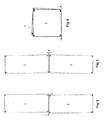
- Figures 2-4 show different examples of how containers 2,3 may happen to stand placed in relation to each other and still be gripped, locked and centred by means of the present invention.
- Figure 2 it is shown from above, e.g., how two containers 2,3 are standing laterally displaced in relation to each other.
- Figure 3 it is shown from above how the containers 2,3 are placed at an angular displacement ⁇ in relation to each other
- Figure 4 it is shown from the side how two containers 2,3 are standing rotated in relation to each other.
- the containers 2,3, can, thanks to the floating and movable saddle construction, easily be gripped, lifted and centred by the container yoke 1 according to the invention.
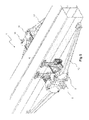
- Figure 5 shows in a view obliquely from above in more detail a container yoke 1 according to the invention having a base frame 4 and two saddles 10,11 placed one after the other in the longitudinal direction of the container yoke 1, and that, by the suspension thereof in link levers 12,13, are displaceable and/or angleable laterally transverse to the longitudinal axis of the container yoke 1.
- the saddles 10,11, and the lock members 9 thereof are somewhat laterally displaced in relation to each other.
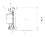
- FIG 6 shows, in a cross-section through the base frame 4 of the container yoke 1, more in detail the components and link levers that are included in one of the saddles 11.
- the locking members 9 are arranged in so-called twinlift boxes 14,15, which are suspended in a respective system of parallel levers wherein an upper link lever 16 attaches the upper part of the twinlift box 14 to the base frame of the container yoke 4 while a lower link lever 17 attaches the lower part of the twinlift box 14 to one end of a vertical link lever 18 in a fulcrum 19a and that at the other end thereof is articulately fixed in the base frame 4 (see also Figures 11 and 12 ).
- both twinlift boxes 14,15 are mechanically coupled to each other, which provides a constant distance between the twinlift boxes 14,15 and the locking members 9a,b irrespective of the lateral position of the saddle 10,11 in relation to the base frame 4.
- the twinlift boxes 14,15 are provided with a respective searching lever 21,22, which makes that, when the twinlift boxes 14,15 and the locking members 9a,b are lowered and not immediately hit the corner box 23,24 of a container 2,3, at least one of the searching levers 21,22 will still always hit a corner or edge of the container 2,3.
- the searching lever 21,22 causes a pulling or pushing force on the nearest twinlift box 14,15, thereby displacing and/or angling the saddle 10,11 laterally outward and away from the base frame 4 of the container yoke 1, so that the locking members 9a,b, e.g. by means of cylinders 26, can be lowered into the lock openings of the corner boxes 23,24 and lock the container 3.
- the horizontal stay 20 then pulls and/or angles the other twinlift box 12,13 inward toward the base frame 4.
- the twinlift boxes 12,13 perform in practice a pendulum motion and the locking members 9 are parallel-moved laterally.
- the lower horizontal transverse stay 20 is provided with a fixed holder-on 25 arranged preferably in the middle of the stay 20.
- two actuators are arranged in the form of hydraulic cylinders 27,28 having piston rods (see Figure 11 ) that are mounted in the base frame 4 of the container yoke 1.
- the outer ends of the piston rods of the cylinders 27,28 are not fixedly coupled, neither to the base frame 4 nor to the stay 20, but when the piston rods are pushed out of the cylinders 27,28 they engage against and presses against said holder-on 25 and thereby displace the horizontal transverse stay 20 and by that the twinlift boxes 14,15 to an centre or vertical position, i.e., a centred position of the saddles 10,11 and/or locking members 9 in relation to the base frame 4.
- the saddle 10,11 and the twinlift boxes 14,15 need to be floating, e.g.
- the piston rods are retracted in the cylinders 27,28, which gives room for the lateral swinging and/or angulation of the saddles 10,11 in relation to the longitudinal axis of the base frame 4.
- the two piston rods are pressed out of the cylinders 27,28 toward the holder-on 25 wherein the horizontal transverse stay 20, and thereby the saddles 10,11 and the lock members 9 thereof, will be centred to said centre or vertical position wherein the two containers 2,3 also will be centred aligned with each other. It is naturally possible, if it would prove advantageous, that the piston rods are pressed out differently much to provide a lateral movement of the containers in another way than with the purpose of centring them.
- the cylinder 26 is arranged between the upper part of the twinlift boxes 14,15 and a lower point of attachment 29 at the base frame 4, by which cylinder 26 lifting and lowering of the twinlift boxes 14,15 and the locking members 9 can be provided.
- the container yoke 1 can first grip and lock to the containers 2,3 at the outer end portions thereof facing away from each other, and not until then to the end portions of the containers 2,3 facing each other.
- Figure 7 shows in a view the container yoke 1 gripping two containers 2,3 placed one after the other, as seen from the end portions of the containers 2,3, wherein it is seen how the saddles 10,11 and/or the locking members 9 have been displaced or angled laterally in relation to each other to be coupleable to the two containers 2,3 simultaneously.
- the outer coupling parts of the container yoke 1 are removed for the sake of clarity.
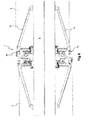
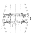
- Figure 8 shows the same position of the saddles 10,11 as in Figure 7 , but from above.
- the containers 2,3 are standing displaced and/or angled laterally in relation to each other and how outer stays 12,13 are articulately arranged between the base frame 4 and the twinlift box 14,15 of the respective saddle 10,11 to allow lateral movement and/or angulation of the saddle 11.
- Figure 9 shows the same position as Figures 7 and 8 , but from below.
- the two saddles 10,11 and the placement of their lower link levers and cylinders are seen.
- the placement of the components shows how the saddles 10,11 have reached and assumed and a respective lateral end position and accordingly the saddles 10,11 are here maximally displaced and/or angled in relation to each other.
- the piston rods 30,31 will press against the holder-on 25 of the intermediate stay 20 and thereby act on the saddles 10,11 to assume a centred and vertical position in relation to the base frame 4.
- Figure 10 shows how the container yoke 1, after initiated lifting, has centred the two containers in relation to each other.
- the cylinders 27,28 have here been supplied with hydraulic oil and the piston rods 30,31 have been pushed out to an outer position and press on both sides of the holder-on 25 of the intermediate stay 20, thereby pressing the saddles 10,11 and the locking members 9 into a centred position.
- FIG 11 shows more clearly the principle of the present invention.
- the saddle 10 is shown in its floating state having two cylinders 27,28 for the centring function. Arrows indicate how link levers and stays can turn around the joints and fixing points thereof.
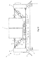
- Figure 12 shows principally an alternative embodiment of the invention.
- the saddle 11 in its floating state has only a single actuator, a hydraulic double cylinder 32, arranged for the centring function.
- the lower horizontal transverse stay 20 is provided with two fixed holder-ons 33,34.
- the hydraulic cylinder 32 is mounted against the base frame 4 of the container yoke 1.
- the cylinder 32 is double-acting and has a piston rod 35,36 directed in each direction. These two piston rods 35,36 can engage with and press against said holder-ons 33,34.
- the piston rods 35,36 are entirely or partly retracted in the cylinder 32, which gives room for the lateral swinging and/or angulation of the saddle 11 in relation to the longitudinal axis of the base frame 4.
- the two piston rods 35,36 are brought to project out of the cylinder 32 toward the respective holder-on 33,34 wherein the horizontal transverse stay 20 will be centred to an centre or vertical position and the two containers 2,3 will be centred aligned with each other.
- the function of the container yoke when gripping containers 2,3 that are standing displaced, with angular displacement or rotated in relation to each other, is accordingly that one or both saddles 10,11 and the locking members 9 arranged therein are displaced and/or angled in relation to each other and/or in relation to the container yoke 1 and in a direction transverse to the longitudinal axis of the container yoke.
- the displacement and/or the angulation are principally accomplished mechanically by means of search levers 21,22 and the saddles 10,11 thus move freely during the steering-in.
- the hydraulic cylinders may, for instance, be exchanged for other types of actuation devices such as electric, pneumatic, magnetic or similar actuators.
- any actuators of a known type may be used.
- centring the containers in a lift it is also naturally possible to use the technique according to the invention to steer the containers into a certain desired position in relation to each other.
- centring or steering could also be achieved without the cylinders operating actively, i.e., the centring could be achieved by the containers by themselves turning into an centre position since they will strive toward an equilibrium position in the middle of the construction, alternatively that this function could be facilitated by, for instance, some resilient member.
Landscapes
- Engineering & Computer Science (AREA)
- Mechanical Engineering (AREA)
- Load-Engaging Elements For Cranes (AREA)
Claims (9)
- Palonnier pour conteneurs (1) pour le levage simultané de deux conteneurs (2,3) l'un placé après l'autre, comprenant un cadre de base (4), des poutres transversales extérieures (7,8) disposées sur le cadre de base (4) et pourvues d'éléments de verrouillage (9) destinés à s'engager dans, et à verrouiller aux parties d'extrémité extérieures des deux conteneurs (2,3) l'une située à l'opposé de l'autre, ainsi qu'au moins deux selles essentiellement centrées (10,11) arrangées au niveau du cadre de base (4) et pourvues de boîtes à levage jumelé "twin-lift" (14,15) ayant des éléments de verrouillage supplémentaires (9) destinés à s'engager dans, et à verrouiller les conteneurs (2,3) à leurs parties d'extrémité extérieures l'une située à l'opposé de l'autre, les éléments de verrouillage (9) de l'une des selles (10) verrouillant l'un des conteneurs (2,3), et les éléments de verrouillage (9) de l'autre selle (11) verrouillant l'autre conteneur (2,3), et des leviers de recherche (21,22) étant agencés pour viser les éléments de verrouillage (9) aux boîtes de coin (23,24) des conteneurs et pour les mettre en engagement avec celles-ci,
caractérisé en- ce que les boîtes à levage jumelé "twin-lift" (14,15) d'une selle respective sont couplées et montées de manière articulée les unes aux autres et au cadre de base (4) au moyen d'un système de leviers parallèles comprenant un étançon inférieur transversal et horizontal (20) pour le déplacement des boîtes à levage jumelé "twin-lift" (14,15) à la partie centrale du cadre de base (4) transversalement à la direction longitudinale du cadre de base (4),- ce que l'étançon inférieur transversal et horizontal (20) est pourvu d'au moins un support fixé (25,33,34),- ce qu'au moins un actionneur (27,28,32) dans le cadre de base (4) est agencé, pendant une phase, de manière à ne pas être en contact mécanique avec l'étançon inférieur transversal et horizontal (20) et laisser le support (25,33,34) et ainsi l'étançon inférieur transversal et horizontal (20) osciller/flotter librement transversalement à la direction longitudinale du cadre de base (4), et- ce que l'actionneur (27,28,32) est agencé, pendant une autre phase, de manière à s'engager mécaniquement avec ledit support (25,33,34) et presser contre celui-ci pour produire un déplacement mécanique de l'étançon inférieur transversal et horizontal (20) et ainsi des selles (10,11) et des conteneurs levés (2,3) dans une position désirée par rapport au cadre de base (4), par exemple afin d'obtenir un centrage des selles (10,11) et des conteneurs (2,3). - Palonnier pour conteneurs selon la revendication 1,
caractérisé en
ce que le support fixé (25) est disposé préférablement dans le centre de l'étançon inférieur transversal et horizontal (20). - Palonnier pour conteneurs selon la revendication 1 ou 2,
caractérisé en
ce que deux actionneurs (27,28) sont disposés dans le cadre de base (4) du palonnier pour conteneurs sur chaque côté du support (25) agencé, par l'intermédiaire des tiges de piston (30,31), pour presser contre le support (25) de l'étançon inférieur transversal et horizontal (20) à partir de deux directions, ainsi déplacer les selles (10,11) par rapport au cadre de base (4). - Palonnier pour conteneurs selon la revendication 1,
caractérisé en
ce que deux supports fixés (33,34) sont disposés sur l'étançon inférieur transversal et horizontal (20). - Palonnier pour conteneurs selon la revendication 1 ou 4,
caractérisé en
ce qu'un seul actionneur (32) est disposé au cadre de base (4) pour s'engager avec lesdits supports (33,34) et presser contre ceux-ci. - Palonnier pour conteneurs selon la revendication 1, 4 ou 5,
caractérisé en
ce que l'actionneur (32) est un cylindre à double action ayant une tige de piston (35,36) orientée dans chaque direction. - Palonnier pour conteneurs selon l'une quelconque des revendications précédentes,
caractérisé en
ce que les deux boîtes à levage jumelé "twin-lift" (14,15) sont mécaniquement couplées l'une à l'autre, ce qui fournit une distance constante entre les boîtes à levage jumelé "twin-lift" (14,15) et les éléments de verrouillage (9a,b) sans tenir compte de la position latérale de la selle (10,11) par rapport au base de cadre (4). - Palonnier pour conteneurs selon l'une quelconque des revendications précédentes,
caractérisé en
ce que les actionneurs (27,28,32) sont disposés au-dessous du cadre de base (4). - Palonnier pour conteneurs selon l'une quelconque des revendications précédentes,
caractérisé en
ce que les actionneurs (27,28,32) sont des cylindres hydrauliques.
Priority Applications (1)
| Application Number | Priority Date | Filing Date | Title |
|---|---|---|---|
| PL10814033T PL2473433T3 (pl) | 2009-09-04 | 2010-09-06 | Jarzmo kontenera do podnoszenia i wyśrodkowania kontenerów |
Applications Claiming Priority (2)
| Application Number | Priority Date | Filing Date | Title |
|---|---|---|---|
| SE0950636A SE534186C2 (sv) | 2009-09-04 | 2009-09-04 | Containerok för lyftning och centrering av containrar |
| PCT/SE2010/050945 WO2011028172A1 (fr) | 2009-09-04 | 2010-09-06 | Palonnier pour conteneurs destiné à lever et centrer des conteneurs |
Publications (3)
| Publication Number | Publication Date |
|---|---|
| EP2473433A1 EP2473433A1 (fr) | 2012-07-11 |
| EP2473433A4 EP2473433A4 (fr) | 2013-07-24 |
| EP2473433B1 true EP2473433B1 (fr) | 2014-11-26 |
Family
ID=43649526
Family Applications (1)
| Application Number | Title | Priority Date | Filing Date |
|---|---|---|---|
| EP10814033.6A Active EP2473433B1 (fr) | 2009-09-04 | 2010-09-06 | Palonnier pour conteneurs destiné à lever et centrer des conteneurs |
Country Status (9)
| Country | Link |
|---|---|
| US (1) | US8585108B2 (fr) |
| EP (1) | EP2473433B1 (fr) |
| CN (1) | CN102482062B (fr) |
| BR (1) | BR112012004981B1 (fr) |
| IN (1) | IN2012DN02622A (fr) |
| MY (1) | MY167200A (fr) |
| PL (1) | PL2473433T3 (fr) |
| SE (1) | SE534186C2 (fr) |
| WO (1) | WO2011028172A1 (fr) |
Families Citing this family (7)
| Publication number | Priority date | Publication date | Assignee | Title |
|---|---|---|---|---|
| FI126621B (fi) * | 2012-05-22 | 2017-03-15 | Oy Langh Ship Ab | Nostoteline tavarankuljetusyksikön nostamiseksi |
| MY198132A (en) | 2016-02-01 | 2023-08-07 | Elme Spreader Ab | Spreader for lifting intermodal container |
| CN106744259A (zh) * | 2016-12-22 | 2017-05-31 | 中国化学工程第三建设有限公司 | 一种多功能吊装护角器及其吊装设备、钢结构的方法 |
| WO2018150153A1 (fr) * | 2017-02-17 | 2018-08-23 | Block Container Systems Limited | Levage de conteneurs d'expédition |
| CN111017703B (zh) * | 2019-12-20 | 2021-10-29 | 三一海洋重工有限公司 | 集装箱吊具及起重机 |
| CN111606214B (zh) * | 2020-06-04 | 2021-02-23 | 西南交通大学 | 一种集装箱用门式起重机 |
| CN118288083B (zh) * | 2024-06-06 | 2024-09-27 | 河南卫华重型机械股份有限公司 | 一种窄长箱梁加工用快速定位夹具 |
Family Cites Families (12)
| Publication number | Priority date | Publication date | Assignee | Title |
|---|---|---|---|---|
| US5280980A (en) * | 1992-12-24 | 1994-01-25 | Earl's Industries Ltd. | Self-aligning twin container spreader |
| DE19516520A1 (de) | 1995-05-05 | 1996-11-07 | Gerhard Geis | Zwillingshebegerät für Container |
| US6145903A (en) * | 1996-04-25 | 2000-11-14 | Stinis Beheer B.V. | Hoisting frame and method for hoisting containers |
| JP3219711B2 (ja) | 1997-01-16 | 2001-10-15 | 三菱重工業株式会社 | コンテナ吊用スプレッダ |
| DE19957823C2 (de) | 1999-11-19 | 2001-10-25 | Atecs Mannesmann Ag | Vorrichtung zum automatisierten Umschlag von Lasten |
| US6863325B1 (en) * | 2000-02-25 | 2005-03-08 | Natsteel Engineering Pte. Ltd. | Lifting device |
| WO2001089979A1 (fr) * | 2000-05-24 | 2001-11-29 | Stinis Beheer B.V. | Dispositif de prise de recipient muni d'elements de contact destines au freinage |
| EP1503951A1 (fr) * | 2002-05-10 | 2005-02-09 | NatSteel Engineering Pte. Ltd. | Systeme de manutention de conteneurs |
| ES2328473T3 (es) * | 2002-06-10 | 2009-11-13 | Stinis Beheer B.V. | Bastidor elevador y metodo de utilizacion. |
| SE527325C2 (sv) * | 2004-07-05 | 2006-02-14 | Elmhults Konstruktions Ab | Containerok |
| KR101125039B1 (ko) * | 2009-12-24 | 2012-03-22 | 한국과학기술원 | 크레인용 스프레더와 이를 구비한 크레인, 크레인을 탑재한 선박 및 크레인용 스프레더의 자동 랜딩 방법 |
| SE535156C2 (sv) * | 2010-01-14 | 2012-05-02 | Elme Spreader Ab | Linstyrt containerok |
-
2009
- 2009-09-04 SE SE0950636A patent/SE534186C2/sv not_active IP Right Cessation
-
2010
- 2010-09-06 MY MYPI2012000945A patent/MY167200A/en unknown
- 2010-09-06 WO PCT/SE2010/050945 patent/WO2011028172A1/fr not_active Ceased
- 2010-09-06 US US13/393,819 patent/US8585108B2/en not_active Expired - Fee Related
- 2010-09-06 EP EP10814033.6A patent/EP2473433B1/fr active Active
- 2010-09-06 CN CN201080039250.6A patent/CN102482062B/zh not_active Expired - Fee Related
- 2010-09-06 PL PL10814033T patent/PL2473433T3/pl unknown
- 2010-09-06 BR BR112012004981-0A patent/BR112012004981B1/pt not_active IP Right Cessation
-
2012
- 2012-03-26 IN IN2622DEN2012 patent/IN2012DN02622A/en unknown
Also Published As
| Publication number | Publication date |
|---|---|
| SE534186C2 (sv) | 2011-05-24 |
| SE0950636A1 (sv) | 2011-03-05 |
| IN2012DN02622A (fr) | 2015-09-04 |
| WO2011028172A1 (fr) | 2011-03-10 |
| EP2473433A4 (fr) | 2013-07-24 |
| BR112012004981B1 (pt) | 2021-08-31 |
| MY167200A (en) | 2018-08-13 |
| BR112012004981A2 (pt) | 2020-09-24 |
| EP2473433A1 (fr) | 2012-07-11 |
| PL2473433T3 (pl) | 2015-05-29 |
| US8585108B2 (en) | 2013-11-19 |
| CN102482062B (zh) | 2014-07-30 |
| CN102482062A (zh) | 2012-05-30 |
| US20120212004A1 (en) | 2012-08-23 |
Similar Documents
| Publication | Publication Date | Title |
|---|---|---|
| EP2473433B1 (fr) | Palonnier pour conteneurs destiné à lever et centrer des conteneurs | |
| CN101475045B (zh) | 一种造船过程中舵叶的吊装方法 | |
| EP3297945B1 (fr) | Outil de levage à bride | |
| EP1855982B1 (fr) | Appareil de levage et de positionnement | |
| US7178846B2 (en) | Device and method for handling containers | |
| NO333885B1 (no) | Anordning ved løfteramme | |
| JP2902589B2 (ja) | 吊りクランプ | |
| CA3072441A1 (fr) | Systeme et methode de levage d'etagere | |
| EP1033342A2 (fr) | Pince de levage pour transporter des bobines de bande métallique | |
| US8814238B2 (en) | Clamping apparatus | |
| EP2483481A1 (fr) | Dispositif d'inclinaison de pieu | |
| JPH10507435A (ja) | 荷重昇降装置 | |
| KR20200054735A (ko) | 선박 대조블록 용접용 대조블록 위치 정렬장치 | |
| WO2010007514A2 (fr) | Matériel de raccordement rapide de charges, en particulier des contenants | |
| CN109531541B (zh) | 一种桁架机器人用夹持装置 | |
| JP2025009828A (ja) | デリックバラストを持つクレーン | |
| US9162852B2 (en) | Method for controlling a concrete mix casting equipment dismountably attached to a crane and a concrete mix casting equipment dismountably attached to a crane | |
| CN106744509A (zh) | 工件精密吊装装置及其工作方法 | |
| CN206427979U (zh) | 工件精密吊装装置 | |
| RU2610770C1 (ru) | Траверса | |
| IT202000025243A1 (it) | Piattaforma di supporto regolabile | |
| CN218988620U (zh) | 一种小型平衡吊装车 | |
| CN218809890U (zh) | 一种缸体抓手装置 | |
| EP1603823B1 (fr) | Repartiteur de levage lateral pour conteneur | |
| US11788676B2 (en) | Docking station for a head block assembly |
Legal Events
| Date | Code | Title | Description |
|---|---|---|---|
| PUAI | Public reference made under article 153(3) epc to a published international application that has entered the european phase |
Free format text: ORIGINAL CODE: 0009012 |
|
| 17P | Request for examination filed |
Effective date: 20120308 |
|
| AK | Designated contracting states |
Kind code of ref document: A1 Designated state(s): AL AT BE BG CH CY CZ DE DK EE ES FI FR GB GR HR HU IE IS IT LI LT LU LV MC MK MT NL NO PL PT RO SE SI SK SM TR |
|
| DAX | Request for extension of the european patent (deleted) | ||
| REG | Reference to a national code |
Ref country code: DE Ref legal event code: R079 Ref document number: 602010020594 Country of ref document: DE Free format text: PREVIOUS MAIN CLASS: B66C0001660000 Ipc: B66C0001100000 |
|
| A4 | Supplementary search report drawn up and despatched |
Effective date: 20130621 |
|
| RIC1 | Information provided on ipc code assigned before grant |
Ipc: B66C 1/10 20060101AFI20130617BHEP Ipc: B66C 1/66 20060101ALI20130617BHEP |
|
| 17Q | First examination report despatched |
Effective date: 20140124 |
|
| GRAP | Despatch of communication of intention to grant a patent |
Free format text: ORIGINAL CODE: EPIDOSNIGR1 |
|
| INTG | Intention to grant announced |
Effective date: 20140717 |
|
| GRAS | Grant fee paid |
Free format text: ORIGINAL CODE: EPIDOSNIGR3 |
|
| GRAA | (expected) grant |
Free format text: ORIGINAL CODE: 0009210 |
|
| AK | Designated contracting states |
Kind code of ref document: B1 Designated state(s): AL AT BE BG CH CY CZ DE DK EE ES FI FR GB GR HR HU IE IS IT LI LT LU LV MC MK MT NL NO PL PT RO SE SI SK SM TR |
|
| REG | Reference to a national code |
Ref country code: GB Ref legal event code: FG4D |
|
| REG | Reference to a national code |
Ref country code: CH Ref legal event code: EP |
|
| REG | Reference to a national code |
Ref country code: AT Ref legal event code: REF Ref document number: 698034 Country of ref document: AT Kind code of ref document: T Effective date: 20141215 |
|
| REG | Reference to a national code |
Ref country code: IE Ref legal event code: FG4D |
|
| REG | Reference to a national code |
Ref country code: DE Ref legal event code: R096 Ref document number: 602010020594 Country of ref document: DE Effective date: 20150108 |
|
| REG | Reference to a national code |
Ref country code: NL Ref legal event code: T3 |
|
| REG | Reference to a national code |
Ref country code: AT Ref legal event code: MK05 Ref document number: 698034 Country of ref document: AT Kind code of ref document: T Effective date: 20141126 |
|
| REG | Reference to a national code |
Ref country code: LT Ref legal event code: MG4D |
|
| PG25 | Lapsed in a contracting state [announced via postgrant information from national office to epo] |
Ref country code: ES Free format text: LAPSE BECAUSE OF FAILURE TO SUBMIT A TRANSLATION OF THE DESCRIPTION OR TO PAY THE FEE WITHIN THE PRESCRIBED TIME-LIMIT Effective date: 20141126 Ref country code: PT Free format text: LAPSE BECAUSE OF FAILURE TO SUBMIT A TRANSLATION OF THE DESCRIPTION OR TO PAY THE FEE WITHIN THE PRESCRIBED TIME-LIMIT Effective date: 20150326 Ref country code: IS Free format text: LAPSE BECAUSE OF FAILURE TO SUBMIT A TRANSLATION OF THE DESCRIPTION OR TO PAY THE FEE WITHIN THE PRESCRIBED TIME-LIMIT Effective date: 20150326 Ref country code: LT Free format text: LAPSE BECAUSE OF FAILURE TO SUBMIT A TRANSLATION OF THE DESCRIPTION OR TO PAY THE FEE WITHIN THE PRESCRIBED TIME-LIMIT Effective date: 20141126 Ref country code: NO Free format text: LAPSE BECAUSE OF FAILURE TO SUBMIT A TRANSLATION OF THE DESCRIPTION OR TO PAY THE FEE WITHIN THE PRESCRIBED TIME-LIMIT Effective date: 20150226 |
|
| PG25 | Lapsed in a contracting state [announced via postgrant information from national office to epo] |
Ref country code: SE Free format text: LAPSE BECAUSE OF FAILURE TO SUBMIT A TRANSLATION OF THE DESCRIPTION OR TO PAY THE FEE WITHIN THE PRESCRIBED TIME-LIMIT Effective date: 20141126 Ref country code: HR Free format text: LAPSE BECAUSE OF FAILURE TO SUBMIT A TRANSLATION OF THE DESCRIPTION OR TO PAY THE FEE WITHIN THE PRESCRIBED TIME-LIMIT Effective date: 20141126 Ref country code: AT Free format text: LAPSE BECAUSE OF FAILURE TO SUBMIT A TRANSLATION OF THE DESCRIPTION OR TO PAY THE FEE WITHIN THE PRESCRIBED TIME-LIMIT Effective date: 20141126 Ref country code: GR Free format text: LAPSE BECAUSE OF FAILURE TO SUBMIT A TRANSLATION OF THE DESCRIPTION OR TO PAY THE FEE WITHIN THE PRESCRIBED TIME-LIMIT Effective date: 20150227 Ref country code: LV Free format text: LAPSE BECAUSE OF FAILURE TO SUBMIT A TRANSLATION OF THE DESCRIPTION OR TO PAY THE FEE WITHIN THE PRESCRIBED TIME-LIMIT Effective date: 20141126 Ref country code: CY Free format text: LAPSE BECAUSE OF FAILURE TO SUBMIT A TRANSLATION OF THE DESCRIPTION OR TO PAY THE FEE WITHIN THE PRESCRIBED TIME-LIMIT Effective date: 20141126 |
|
| REG | Reference to a national code |
Ref country code: PL Ref legal event code: T3 |
|
| PG25 | Lapsed in a contracting state [announced via postgrant information from national office to epo] |
Ref country code: DK Free format text: LAPSE BECAUSE OF FAILURE TO SUBMIT A TRANSLATION OF THE DESCRIPTION OR TO PAY THE FEE WITHIN THE PRESCRIBED TIME-LIMIT Effective date: 20141126 Ref country code: CZ Free format text: LAPSE BECAUSE OF FAILURE TO SUBMIT A TRANSLATION OF THE DESCRIPTION OR TO PAY THE FEE WITHIN THE PRESCRIBED TIME-LIMIT Effective date: 20141126 Ref country code: EE Free format text: LAPSE BECAUSE OF FAILURE TO SUBMIT A TRANSLATION OF THE DESCRIPTION OR TO PAY THE FEE WITHIN THE PRESCRIBED TIME-LIMIT Effective date: 20141126 Ref country code: SK Free format text: LAPSE BECAUSE OF FAILURE TO SUBMIT A TRANSLATION OF THE DESCRIPTION OR TO PAY THE FEE WITHIN THE PRESCRIBED TIME-LIMIT Effective date: 20141126 Ref country code: RO Free format text: LAPSE BECAUSE OF FAILURE TO SUBMIT A TRANSLATION OF THE DESCRIPTION OR TO PAY THE FEE WITHIN THE PRESCRIBED TIME-LIMIT Effective date: 20141126 |
|
| REG | Reference to a national code |
Ref country code: DE Ref legal event code: R097 Ref document number: 602010020594 Country of ref document: DE |
|
| PLBE | No opposition filed within time limit |
Free format text: ORIGINAL CODE: 0009261 |
|
| STAA | Information on the status of an ep patent application or granted ep patent |
Free format text: STATUS: NO OPPOSITION FILED WITHIN TIME LIMIT |
|
| 26N | No opposition filed |
Effective date: 20150827 |
|
| PG25 | Lapsed in a contracting state [announced via postgrant information from national office to epo] |
Ref country code: SI Free format text: LAPSE BECAUSE OF FAILURE TO SUBMIT A TRANSLATION OF THE DESCRIPTION OR TO PAY THE FEE WITHIN THE PRESCRIBED TIME-LIMIT Effective date: 20141126 |
|
| PG25 | Lapsed in a contracting state [announced via postgrant information from national office to epo] |
Ref country code: LU Free format text: LAPSE BECAUSE OF FAILURE TO SUBMIT A TRANSLATION OF THE DESCRIPTION OR TO PAY THE FEE WITHIN THE PRESCRIBED TIME-LIMIT Effective date: 20150906 Ref country code: MC Free format text: LAPSE BECAUSE OF FAILURE TO SUBMIT A TRANSLATION OF THE DESCRIPTION OR TO PAY THE FEE WITHIN THE PRESCRIBED TIME-LIMIT Effective date: 20141126 |
|
| REG | Reference to a national code |
Ref country code: CH Ref legal event code: PL |
|
| GBPC | Gb: european patent ceased through non-payment of renewal fee |
Effective date: 20150906 |
|
| REG | Reference to a national code |
Ref country code: IE Ref legal event code: MM4A |
|
| REG | Reference to a national code |
Ref country code: FR Ref legal event code: ST Effective date: 20160531 |
|
| PG25 | Lapsed in a contracting state [announced via postgrant information from national office to epo] |
Ref country code: CH Free format text: LAPSE BECAUSE OF NON-PAYMENT OF DUE FEES Effective date: 20150930 Ref country code: LI Free format text: LAPSE BECAUSE OF NON-PAYMENT OF DUE FEES Effective date: 20150930 Ref country code: IE Free format text: LAPSE BECAUSE OF NON-PAYMENT OF DUE FEES Effective date: 20150906 Ref country code: GB Free format text: LAPSE BECAUSE OF NON-PAYMENT OF DUE FEES Effective date: 20150906 |
|
| PG25 | Lapsed in a contracting state [announced via postgrant information from national office to epo] |
Ref country code: FR Free format text: LAPSE BECAUSE OF NON-PAYMENT OF DUE FEES Effective date: 20150930 |
|
| PG25 | Lapsed in a contracting state [announced via postgrant information from national office to epo] |
Ref country code: MT Free format text: LAPSE BECAUSE OF FAILURE TO SUBMIT A TRANSLATION OF THE DESCRIPTION OR TO PAY THE FEE WITHIN THE PRESCRIBED TIME-LIMIT Effective date: 20141126 |
|
| PG25 | Lapsed in a contracting state [announced via postgrant information from national office to epo] |
Ref country code: BG Free format text: LAPSE BECAUSE OF FAILURE TO SUBMIT A TRANSLATION OF THE DESCRIPTION OR TO PAY THE FEE WITHIN THE PRESCRIBED TIME-LIMIT Effective date: 20141126 Ref country code: SM Free format text: LAPSE BECAUSE OF FAILURE TO SUBMIT A TRANSLATION OF THE DESCRIPTION OR TO PAY THE FEE WITHIN THE PRESCRIBED TIME-LIMIT Effective date: 20141126 Ref country code: HU Free format text: LAPSE BECAUSE OF FAILURE TO SUBMIT A TRANSLATION OF THE DESCRIPTION OR TO PAY THE FEE WITHIN THE PRESCRIBED TIME-LIMIT; INVALID AB INITIO Effective date: 20100906 |
|
| PG25 | Lapsed in a contracting state [announced via postgrant information from national office to epo] |
Ref country code: TR Free format text: LAPSE BECAUSE OF FAILURE TO SUBMIT A TRANSLATION OF THE DESCRIPTION OR TO PAY THE FEE WITHIN THE PRESCRIBED TIME-LIMIT Effective date: 20141126 |
|
| PG25 | Lapsed in a contracting state [announced via postgrant information from national office to epo] |
Ref country code: BE Free format text: LAPSE BECAUSE OF FAILURE TO SUBMIT A TRANSLATION OF THE DESCRIPTION OR TO PAY THE FEE WITHIN THE PRESCRIBED TIME-LIMIT Effective date: 20141126 |
|
| PG25 | Lapsed in a contracting state [announced via postgrant information from national office to epo] |
Ref country code: MK Free format text: LAPSE BECAUSE OF FAILURE TO SUBMIT A TRANSLATION OF THE DESCRIPTION OR TO PAY THE FEE WITHIN THE PRESCRIBED TIME-LIMIT Effective date: 20141126 |
|
| PG25 | Lapsed in a contracting state [announced via postgrant information from national office to epo] |
Ref country code: AL Free format text: LAPSE BECAUSE OF FAILURE TO SUBMIT A TRANSLATION OF THE DESCRIPTION OR TO PAY THE FEE WITHIN THE PRESCRIBED TIME-LIMIT Effective date: 20141126 |
|
| PGFP | Annual fee paid to national office [announced via postgrant information from national office to epo] |
Ref country code: IT Payment date: 20210924 Year of fee payment: 12 Ref country code: FI Payment date: 20210921 Year of fee payment: 12 |
|
| PGFP | Annual fee paid to national office [announced via postgrant information from national office to epo] |
Ref country code: PL Payment date: 20210806 Year of fee payment: 12 |
|
| PG25 | Lapsed in a contracting state [announced via postgrant information from national office to epo] |
Ref country code: FI Free format text: LAPSE BECAUSE OF NON-PAYMENT OF DUE FEES Effective date: 20220906 |
|
| PG25 | Lapsed in a contracting state [announced via postgrant information from national office to epo] |
Ref country code: IT Free format text: LAPSE BECAUSE OF NON-PAYMENT OF DUE FEES Effective date: 20220906 |
|
| PG25 | Lapsed in a contracting state [announced via postgrant information from national office to epo] |
Ref country code: PL Free format text: LAPSE BECAUSE OF NON-PAYMENT OF DUE FEES Effective date: 20220906 |
|
| PGFP | Annual fee paid to national office [announced via postgrant information from national office to epo] |
Ref country code: NL Payment date: 20250717 Year of fee payment: 16 |
|
| PGFP | Annual fee paid to national office [announced via postgrant information from national office to epo] |
Ref country code: DE Payment date: 20250820 Year of fee payment: 16 |