EP2473747B1 - Rivet aveugle - Google Patents
Rivet aveugle Download PDFInfo
- Publication number
- EP2473747B1 EP2473747B1 EP10752221.1A EP10752221A EP2473747B1 EP 2473747 B1 EP2473747 B1 EP 2473747B1 EP 10752221 A EP10752221 A EP 10752221A EP 2473747 B1 EP2473747 B1 EP 2473747B1
- Authority
- EP
- European Patent Office
- Prior art keywords
- rivet
- blind
- ribs
- flange
- assembly
- Prior art date
- Legal status (The legal status is an assumption and is not a legal conclusion. Google has not performed a legal analysis and makes no representation as to the accuracy of the status listed.)
- Active
Links
Images


Classifications
-
- F—MECHANICAL ENGINEERING; LIGHTING; HEATING; WEAPONS; BLASTING
- F16—ENGINEERING ELEMENTS AND UNITS; GENERAL MEASURES FOR PRODUCING AND MAINTAINING EFFECTIVE FUNCTIONING OF MACHINES OR INSTALLATIONS; THERMAL INSULATION IN GENERAL
- F16B—DEVICES FOR FASTENING OR SECURING CONSTRUCTIONAL ELEMENTS OR MACHINE PARTS TOGETHER, e.g. NAILS, BOLTS, CIRCLIPS, CLAMPS, CLIPS OR WEDGES; JOINTS OR JOINTING
- F16B19/00—Bolts without screw-thread; Pins, including deformable elements; Rivets
- F16B19/04—Rivets; Spigots or the like fastened by riveting
- F16B19/08—Hollow rivets; Multi-part rivets
- F16B19/10—Hollow rivets; Multi-part rivets fastened by expanding mechanically
- F16B19/1027—Multi-part rivets
- F16B19/1036—Blind rivets
- F16B19/1045—Blind rivets fastened by a pull - mandrel or the like
-
- B—PERFORMING OPERATIONS; TRANSPORTING
- B21—MECHANICAL METAL-WORKING WITHOUT ESSENTIALLY REMOVING MATERIAL; PUNCHING METAL
- B21J—FORGING; HAMMERING; PRESSING METAL; RIVETING; FORGE FURNACES
- B21J15/00—Riveting
- B21J15/02—Riveting procedures
- B21J15/04—Riveting hollow rivets mechanically
- B21J15/043—Riveting hollow rivets mechanically by pulling a mandrel
-
- B—PERFORMING OPERATIONS; TRANSPORTING
- B21—MECHANICAL METAL-WORKING WITHOUT ESSENTIALLY REMOVING MATERIAL; PUNCHING METAL
- B21J—FORGING; HAMMERING; PRESSING METAL; RIVETING; FORGE FURNACES
- B21J15/00—Riveting
- B21J15/10—Riveting machines
- B21J15/36—Rivet sets, i.e. tools for forming heads; Mandrels for expanding parts of hollow rivets
- B21J15/365—Mandrels for expanding parts of hollow rivets
-
- Y—GENERAL TAGGING OF NEW TECHNOLOGICAL DEVELOPMENTS; GENERAL TAGGING OF CROSS-SECTIONAL TECHNOLOGIES SPANNING OVER SEVERAL SECTIONS OF THE IPC; TECHNICAL SUBJECTS COVERED BY FORMER USPC CROSS-REFERENCE ART COLLECTIONS [XRACs] AND DIGESTS
- Y10—TECHNICAL SUBJECTS COVERED BY FORMER USPC
- Y10T—TECHNICAL SUBJECTS COVERED BY FORMER US CLASSIFICATION
- Y10T29/00—Metal working
- Y10T29/49—Method of mechanical manufacture
- Y10T29/49826—Assembling or joining
- Y10T29/49947—Assembling or joining by applying separate fastener
- Y10T29/49954—Fastener deformed after application
- Y10T29/49956—Riveting
Definitions
- the present invention relates to blind rivets, and relates particularly to a blind rivet having a mandrel with a deformable mandrel head.
- blind rivets which are well known in the art, are used to attach two pieces of material together by means of access to one side of the material.
- Figures 1 a-d illustrate a blind rivet 100, known as a break stem rivet, used to join together two pieces of material 102.
- the blind rivet 100 has a cylindrical rivet body portion 104 with a flange 106 at one end.
- a mandrel 107 which has an elongated mandrel stem 108 and a head portion 110 at one end, is fed through the rivet body portion 104 such that the head portion 110 of the mandrel 107 engages the opposite end of the rivet body portion 104 to that from which the flange 106 extends.
- the blind rivet 100 is fed through two overlapping apertures in the pieces of material 102 to be joined together such that the flange 106 engages one of the pieces of material 102.
- a force F1 is applied to the mandrel stem 108 in a direction away from the pieces of material 102, and a force F2 is also applied to the flange portion 106 in an opposite direction to that of force F1.
- the force F1 applied to the mandrel stem 108 causes the mandrel head 110 to exert a force on the rivet body portion 104 of the blind rivet 100.
- Such a force causes deformation of the rivet body portion 104 as the mandrel head 110 is pulled towards the pieces of material 102 being joined together, resulting in the creation of an additional flange portion 114.
- the mandrel head 110 is pulled through the rivet body portion 104 of the blind rivet 100 until the additional flange portion 114 engages the material 102.
- the mandrel head 110 is made of harder material than the mandrel stem 108 such that the mandrel stem 108 breaks away from the mandrel head 110 on further application of the force F1 after the additional flange portion 114 engages the material 102. Following this process the two pieces of material 102 are therefore joined together and held in place by the flange 106 and additional flange portion 114.
- Pull through blind rivets are also known in the art. Pull through rivets differ from break stem rivets described also in that the mandrel stem does not break away from the mandrel head, and the mandrel head is pulled entirely through the rivet body portion of the blind rivet, and is disposed of with the mandrel stem.
- U.S. Patent No. 4,497,603 discloses such a pull through blind rivet.
- JP 8 086304 A shows the features of the preamble of claim 1.
- a problem with conventional break stem and pull through blind rivets is that it is difficult to reliably join pieces of material having dissimilar sized apertures extending therethrough.
- the rivet body portion 104 of the blind rivet 100 would not engage the entirety of the inner surface defined by the wider aperture. This may then allow the piece of material having the slightly wider aperture to move in a transverse direction.
- this problem would be rectified by drilling a wider aperture in the piece of material 102 having the smaller aperture such that the apertures in the two pieces of material 102 to be joined are of substantially the same size. This complicates and increases the cost of a manufacturing process.
- Preferred embodiments of the present invention seek to overcome one or more of the above disadvantages of the prior art.
- a deformable mandrel head provides the advantage that a blind rivet can be used to fixably attach pieces of material together having dissimilar sized apertures extending therethrough.
- said mandrel head has a tapering cross section.
- said mandrel head has a substantially part-conical cross-section. This allows the mandrel head to slightly enter the rivet body portion prior to its deformation providing the advantage that the rivet body portion is evenly deformed around the aperture extending through it.
- said elongated portion has a plurality of first ribs arranged on an outer surface thereof for engaging an aperture in a work piece. This increases the grip of the rivet on the work piece thereby providing the advantage of minimizing rotation of the work piece relative to the rivet and vice versa.
- a plurality of said first ribs extends substantially parallel to a longitudinal axis of said elongated portion.
- said flange has a plurality of second ribs arranged thereon for engaging an edge of an aperture in a work piece. This increases the grip of the rivet on the work piece thereby providing the advantage of minimizing rotation of the work piece relative to the rivet and vice versa.
- a plurality of said second ribs extend transversely to a longitudinal axis of said elongated portion.
- said bore extends the entire length of said elongated portion.
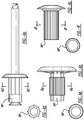
- FIG. 2 illustrates a pull through blind rivet 200 embodying the present invention.
- the blind rivet 200 has a cylindrical rivet body portion 202 having a bore 204 extending entirely through it along an axis 206.
- the rivet body portion 202 has a flange portion 208 extending from it at one end, and has a partially ribbed outer surface 210.
- the flange portion 208 also has a ribbed surface 212 on the side of the flange facing the direction of the rivet body portion 202.
- a mandrel 214 having an elongated mandrel stem 216 and a deformable mandrel head 218 extends through the bore 204 in the rivet body portion 202.
- the mandrel head 218 is wider than the bore 204 extending through the rivet body portion 202.
- the mandrel is secured to the rivet body prior to setting by an interference fit between the stem and the bore of the rivet body.
- the pieces of material 220, 222 having large and small apertures 221, 223, respectively extending therethrough, are placed in engagement with one another such that the apertures extending therethrough are aligned.
- the blind rivet 200 is then fed through the aligned apertures in the pieces of material 220, 222 such that the flange portion 208 abuts the surface of the material 222 having the smaller of the two apertures.
- a force F1 is then applied to the mandrel stem 216 in a direction away from the rivet body portion 202 along axis 206, and a force F2 is applied to the flange portion 208 in the direction of the rivet body portion 202 in a direction opposite to that of force F1.
- the force F1 pulls the mandrel stem 216 away from the rivet body portion 202 and causes the mandrel head 218 to be pulled into the bore 204 extending through the rivet body portion 202.
- the tapered surface on the side of the mandrel head 218 adjacent the mandrel stem 216 is brought into engagement with the rivet body portion 202 as the mandrel 214 is pulled away from the rivet body portion 202.
- Figure 3c illustrates the mandrel head 218 having deformed a sufficient amount to fit through the larger aperture in material piece 220.
- the mandrel body portion 202 deforms further such that it is brought into engagement with the inner surface defined by the aperture in material piece 220.
- the mandrel head 218 As the mandrel head 218 is pulled further through the bore 204 in the rivet body portion 202, the mandrel head 218 deforms further such that it can fit through the smaller aperture in material piece 222, which is narrower than the width of the mandrel head 218 after being pulled through the larger aperture in material piece 220.
- the mandrel head 218 is therefore deformed a sufficient amount such that it may be pulled through the smaller aperture in material piece 222, and as it is pulled through this aperture, the mandrel body portion 202 is again further deformed such that it is brought into engagement with the inner surface defined by the smaller aperture in material piece 222.
- the mandrel stem 216 and mandrel head 218 are then pulled such that they are completely separated from the rivet body portion 202 as illustrated in Figure 3d .
- the two pieces of material 220, 222 are joined together in such a way that they can not move relative to each other.
- the ribs 210 (see Figure 2 ) on the outer surface of the rivet body portion 202 engage the inner surfaces of the apertures in both material pieces 220, 222 so as to increase the grip of the rivet body portion 202 on the pieces of material 220, 222 and thereby prevent rotation of the joined pieces of material 220, 222 about the rivet body portion 202.
- the outer surface of the rivet body portion 202, and therefore the flange 208 extending from it deform in such a way that the ribbed surface 212 (see Figure 2 ) of the flange 208 is forced against the material piece 222 thereby preventing rotation of the rivet body portion 202 relative to the material piece 222.
- the rivet body is thereby permanently fastened to the workpieces during normal use.
- the blind rivet 200 is able to form a joint between the two pieces of material which has earth or grounding continuity.
- workpiece 220 is a conductive metal eyelet attached to an electrical wire and workpiece 222 is a stamped steel panel of an automotive vehicle or electronic cabinet, such as a computer or server chassis.
- the panel workpiece 222 acts as a grounded electrical conductor if electricity flows to it from conductive eyelet 220.
- workpiece 222 may be the eyelet and workpiece 220 may be the grounding panel whereby ribs 212 of flange 208 dig into and deter eyelet 222 from rotation. In these examples, it is desireable to deter rotation of the conductive eyelet relative to the adjacent panel by way of the blind rivet ribs 210 and 212.
- Figure 4 illustrates various other rivet body portion 202 outer surface configurations.
- Figures 4a and 4d illustrate a rivet body portion 202' having a partially splined outer surface
- Figures 4b, 4c, 4e and 4f illustrate a rivet body portion having a partially (202") and entirely (202"') ribbed outer surface, respectively.
- the outer surface of the rivet body section is free of discontinuities (i.e., circular-cylindrically smooth) between the axially elongated ribs on the body section and the laterally elongated ribs on the underside of the flange.
- blind rivet of the present invention may be used to join more than two pieces of material together.
Landscapes
- Engineering & Computer Science (AREA)
- Mechanical Engineering (AREA)
- General Engineering & Computer Science (AREA)
- Insertion Pins And Rivets (AREA)
- Connection Of Plates (AREA)
Claims (15)
- Ensemble de rivet aveugle comprenant :un corps de rivet (202) incluant une section médiane présentant un trou débouchant sensiblement cylindrique (204) au moins avant la pose du rivet aveugle, une bride (208) s'étendant latéralement depuis une extrémité d'outil de la section médiane et un ensemble de nervures (212) s'étendant depuis un côté inférieur de la bride ;un mandrin (214) incluant une tige axialement allongée (216) et une tête latéralement agrandie (218) s'étendant de manière adjacente à une extrémité de la tige, la tige s'étendant par le trou du corps de rivet avant la pose du rivet aveugle, caractérisé en ce que la tête se déforme pendant la pose du rivet aveugle lorsqu'elle est tirée complètement par le corps de rivet ; etau moins deux pièces de travail (220, 222) fixées ensemble par le rivet, des ouvertures internes des pièces de travail (221, 223) ayant des dimensions latérales alignées mais intentionnellement différentes, la bride butant contre une surface de la pièce de travail (222) présentant une dimension plus petite des dimensions latérales.
- Ensemble de rivet aveugle selon la revendication 1, comprenant en outre une surface extérieure de la section médiane du corps de rivet qui est latéralement étendue de manière axialement étagée pour remplir les ouvertures internes lorsque la tête de mandrin est tirée par le corps de rivet.
- Ensemble de rivet aveugle selon la revendication 2, dans lequel au moins l'une des pièces de travail agit comme une masse et conduit de l'électricité.
- Ensemble de rivet aveugle selon la revendication 2, dans lequel l'une des pièces de travail est un oeillet électrique et est empêchée de tourner par engagement de celui-ci par les nervures.
- Ensemble de rivet aveugle selon la revendication 2, comprenant en outre un second ensemble de nervures axialement allongées (210) faisant saillie d'une surface extérieure du corps de rivet au moins avant la pose du rivet.
- Ensemble de rivet aveugle selon la revendication 5, dans lequel la surface extérieure du corps de rivet (202) est lisse de manière cylindrique et circulaire et exempte de discontinuités entre le second ensemble de nervures axialement allongées (210) et les nervures (212) sur la bride.
- Ensemble de rivet aveugle selon la revendication 5, dans lequel le second ensemble de nervures axialement allongées (210) est parallèle à un axe de mandrin allongé avant la pose du rivet.
- Ensemble de rivet aveugle selon la revendication 1, comprenant en outre un second ensemble de nervures allongées axialement en saillie radiale du corps de rivet aveugle parallèle à un axe de mandrin allongé avant la pose du rivet, le second ensemble de nervures engagent les ouvertures des pièces de travail.
- Ensemble de rivet aveugle selon la revendication 2, dans lequel la bride et une section arrière latéralement étendue (224) du corps de rivet s'étendent axialement au-delà des surfaces extérieures des pièces de travail fixées après la pose du rivet, les nervures de la bride engageant l'une pièce adjacente des pièces de travail pour empêcher le mouvement de rotation entre elles.
- Ensemble de rivet aveugle selon la revendication 1, dans lequel la section médiane du corps de rivet a un étage axial dans une surface extérieure de celle-ci entre une section arrière aveugle étendue latéralement (224) et la bride après la pose du rivet.
- Ensemble de rivet aveugle selon la revendication 1, dans lequel chacune des nervures (212) est anglée de sorte à faire saillie axialement d'une plus grande distance de la bride plus près de la section médiane et les nervures de la bride touchent aussi contre la section médiane du corps de rivet.
- Ensemble de rivet aveugle selon la revendication 1, dans lequel l'extrémité aveugle du corps de rivet fait saillie vers l'extérieur et l'arrière loin de la bride et de la section médiane après la pose du rivet.
- Ensemble de rivet aveugle selon la revendication 1, dans lequel le mandrin (214) est fixé au corps de rivet par un ajustement serré avant la pose du rivet.
- Ensemble de rivet aveugle selon la revendication 1, comprenant en outre des nervures axialement allongées (210) parallèles à un axe de mandrin allongé avant la pose du rivet et chacune des nervures présentant une forme de section transversale triangulaire avant la pose du rivet.
- Ensemble de rivet aveugle selon la revendication 1, comprenant en outre :une surface extérieure de la section médiane du corps de rivet qui est latéralement étendue de manière axialement étagée pour remplir une ouverture plus grande (221) des ouvertures internes suivies par la plus petite (223) des ouvertures internes lorsque la tête de mandrin (218) est tirée par le corps de rivet ; etune extrémité aveugle latéralement étendue (224) du corps de rivet aveugle s'étendant axialement au-delà de la surface extérieure adjacente de pièces de travail fixées après la pose du rivet ;dans lequel l'extrémité aveugle du corps de rivet fait saillie vers l'extérieur et l'arrière loin de la bride et de la section médiane après la pose du rivet et le mandrin (214) est fixé au corps de rivet par un ajustement serré avant la pose du rivet.
Applications Claiming Priority (2)
| Application Number | Priority Date | Filing Date | Title |
|---|---|---|---|
| US23627009P | 2009-08-24 | 2009-08-24 | |
| PCT/US2010/046111 WO2011028440A1 (fr) | 2009-08-24 | 2010-08-20 | Rivet aveugle |
Publications (2)
| Publication Number | Publication Date |
|---|---|
| EP2473747A1 EP2473747A1 (fr) | 2012-07-11 |
| EP2473747B1 true EP2473747B1 (fr) | 2016-03-23 |
Family
ID=43126898
Family Applications (1)
| Application Number | Title | Priority Date | Filing Date |
|---|---|---|---|
| EP10752221.1A Active EP2473747B1 (fr) | 2009-08-24 | 2010-08-20 | Rivet aveugle |
Country Status (5)
| Country | Link |
|---|---|
| US (1) | US20120210557A1 (fr) |
| EP (1) | EP2473747B1 (fr) |
| JP (1) | JP2013502551A (fr) |
| CN (1) | CN202811735U (fr) |
| WO (1) | WO2011028440A1 (fr) |
Cited By (2)
| Publication number | Priority date | Publication date | Assignee | Title |
|---|---|---|---|---|
| DE102019111863A1 (de) * | 2019-05-07 | 2020-11-12 | Paxos Consulting & Engineering GmbH & Co. KG | Blindniet zur Befestigung von länglichen Elementen an einem Bauteil |
| DE102022127719A1 (de) * | 2022-10-20 | 2024-04-25 | Bayerische Motoren Werke Aktiengesellschaft | Dornbruchblindniet und Verfahren zum Herstellen einer elektrisch leitenden Nietverbindung |
Families Citing this family (12)
| Publication number | Priority date | Publication date | Assignee | Title |
|---|---|---|---|---|
| US20120034045A1 (en) * | 2010-08-06 | 2012-02-09 | Allfast Fastening Systems, Inc. | Temporary Rivet |
| JP2012077769A (ja) * | 2010-09-30 | 2012-04-19 | Nippon Pop Rivets & Fasteners Ltd | ブラインドリベット及びその締結方法 |
| EP2689867A1 (fr) * | 2012-07-27 | 2014-01-29 | GESIPA Blindniettechnik GmbH | Élément de liaison et appareil de fixation pour un élément de liaison |
| JP6197413B2 (ja) * | 2013-07-03 | 2017-09-20 | 株式会社ジェイテクト | 保持器および保持器の製造方法 |
| JP6294749B2 (ja) * | 2014-04-24 | 2018-03-14 | 盟和産業株式会社 | 中空ボード |
| DE102014208513B4 (de) * | 2014-05-07 | 2021-01-21 | Bayerische Motoren Werke Aktiengesellschaft | Verfahren zur Befestigung mehrerer Werkstücke mittels eines hohlen Nietelements |
| KR20190039711A (ko) * | 2016-08-12 | 2019-04-15 | 일리노이즈 툴 워크스 인코포레이티드 | 리벳 파스너 조립체 |
| EP3732381B8 (fr) * | 2017-12-27 | 2026-03-04 | Allfast Fastening Systems, LLC | Élément de fixation par agrafage |
| KR102673304B1 (ko) * | 2019-06-28 | 2024-06-10 | 현대자동차주식회사 | 차량용 사이드실 |
| US11585363B1 (en) * | 2019-10-28 | 2023-02-21 | National Technology & Engineering Solutions Of Sandia, Llc | Wire rivet |
| CN110762100A (zh) * | 2019-11-28 | 2020-02-07 | 眉山中车紧固件科技有限公司 | 一种用于导电材料紧固连接的拉铆钉 |
| CN115234562A (zh) * | 2022-07-28 | 2022-10-25 | 湖北博士隆科技有限公司 | 折叠式全铝接电螺柱 |
Citations (3)
| Publication number | Priority date | Publication date | Assignee | Title |
|---|---|---|---|---|
| JPH1113723A (ja) * | 1997-06-20 | 1999-01-22 | Ricoh Co Ltd | リベット締結用構造体 |
| JP2004286088A (ja) * | 2003-03-20 | 2004-10-14 | Nippon Pop Rivets & Fasteners Ltd | 締結具 |
| WO2006128652A1 (fr) * | 2005-05-31 | 2006-12-07 | Sumanjit Singh | Rivet |
Family Cites Families (21)
| Publication number | Priority date | Publication date | Assignee | Title |
|---|---|---|---|---|
| FR724509A (fr) * | 1931-10-14 | 1932-04-28 | Liore Et Olivier Ets | Dispositif de rivetage |
| US4164807A (en) * | 1974-03-19 | 1979-08-21 | King John O Jun | Method of forming a coldworked joint |
| US4405273A (en) * | 1977-07-19 | 1983-09-20 | Huck Manufacturing Company | Blind fasteners |
| US4497603A (en) | 1982-06-28 | 1985-02-05 | Usm Corporation | Pull through blind rivet |
| JPH0266707U (fr) * | 1988-11-01 | 1990-05-21 | ||
| JPH08128425A (ja) * | 1994-11-02 | 1996-05-21 | Mitsubishi Chem Corp | リベットの施工方法および当該施工方法で得られた建築資材 |
| JPH0886304A (ja) * | 1994-09-19 | 1996-04-02 | Hitachi Ltd | リブ付きブラインドリベット |
| DE19646668A1 (de) * | 1996-11-12 | 1998-05-14 | Sfs Ind Holding Ag | In ein Sackloch einsetzbares Befestigungselement |
| JP2001027212A (ja) * | 1999-07-12 | 2001-01-30 | Nissin Electric Co Ltd | 導通用リベット |
| JP4365991B2 (ja) * | 2000-05-29 | 2009-11-18 | 三菱化学株式会社 | 電池接続構造 |
| US6746192B2 (en) * | 2001-12-27 | 2004-06-08 | Textron Inc. | Anti-rotation tacking rivet having ribs |
| JP2003322124A (ja) * | 2002-04-26 | 2003-11-14 | Nippon Pop Rivets & Fasteners Ltd | ブラインドリベット及び締結方法 |
| AU2003266340A1 (en) * | 2002-09-04 | 2004-03-29 | Newfrey Llc | Fastening element, particularly for blind rivets |
| JP4357818B2 (ja) * | 2002-09-13 | 2009-11-04 | 株式会社リコー | 部材締結方法およびこの方法に用いる構造体 |
| US6817079B2 (en) * | 2002-11-20 | 2004-11-16 | Falcon Fasteners Reg'd | Method of riveting a headed fastener |
| US7722303B2 (en) * | 2005-02-11 | 2010-05-25 | Newfrey Llc | Frangible blind rivet |
| US7173206B2 (en) * | 2005-04-22 | 2007-02-06 | Tyco Electronics Canada Ltd. | Sealed soft switch assemblies |
| US20070044292A1 (en) * | 2005-08-30 | 2007-03-01 | Robin Stevenson | Method for blind rivet welding |
| US7352176B1 (en) * | 2006-08-10 | 2008-04-01 | Sandia Corporation | Rotating concave eddy current probe |
| US7824141B2 (en) * | 2007-08-03 | 2010-11-02 | Newfrey Llc | Blind rivet |
| US8096742B2 (en) * | 2007-08-03 | 2012-01-17 | Newfrey Llc | Blind rivet |
-
2010
- 2010-08-20 EP EP10752221.1A patent/EP2473747B1/fr active Active
- 2010-08-20 CN CN2010900012610U patent/CN202811735U/zh not_active Expired - Lifetime
- 2010-08-20 JP JP2012526856A patent/JP2013502551A/ja active Pending
- 2010-08-20 WO PCT/US2010/046111 patent/WO2011028440A1/fr not_active Ceased
- 2010-08-20 US US13/391,963 patent/US20120210557A1/en not_active Abandoned
Patent Citations (3)
| Publication number | Priority date | Publication date | Assignee | Title |
|---|---|---|---|---|
| JPH1113723A (ja) * | 1997-06-20 | 1999-01-22 | Ricoh Co Ltd | リベット締結用構造体 |
| JP2004286088A (ja) * | 2003-03-20 | 2004-10-14 | Nippon Pop Rivets & Fasteners Ltd | 締結具 |
| WO2006128652A1 (fr) * | 2005-05-31 | 2006-12-07 | Sumanjit Singh | Rivet |
Cited By (2)
| Publication number | Priority date | Publication date | Assignee | Title |
|---|---|---|---|---|
| DE102019111863A1 (de) * | 2019-05-07 | 2020-11-12 | Paxos Consulting & Engineering GmbH & Co. KG | Blindniet zur Befestigung von länglichen Elementen an einem Bauteil |
| DE102022127719A1 (de) * | 2022-10-20 | 2024-04-25 | Bayerische Motoren Werke Aktiengesellschaft | Dornbruchblindniet und Verfahren zum Herstellen einer elektrisch leitenden Nietverbindung |
Also Published As
| Publication number | Publication date |
|---|---|
| US20120210557A1 (en) | 2012-08-23 |
| CN202811735U (zh) | 2013-03-20 |
| EP2473747A1 (fr) | 2012-07-11 |
| WO2011028440A1 (fr) | 2011-03-10 |
| JP2013502551A (ja) | 2013-01-24 |
Similar Documents
| Publication | Publication Date | Title |
|---|---|---|
| EP2473747B1 (fr) | Rivet aveugle | |
| US9003634B2 (en) | Blind rivet and fastening method thereof | |
| US4969785A (en) | Fastener mandrel and method | |
| EP3177530B1 (fr) | Agencement constitué d'un manchon de remplissage de trou et d'une rondelle, et destiné à l'installation d'un boulon | |
| CA2537081C (fr) | Contre-ecrou | |
| EP0887565A2 (fr) | Ecrou aveugle avec filetage | |
| KR20180096487A (ko) | 억지 끼워맞춤 패스너들을 위한 테이퍼형 인입부 | |
| US7717659B2 (en) | Zero-clearance bolted joint | |
| US8529177B2 (en) | Integrated pin/sleeve blind fastener | |
| MXPA00008522A (es) | Tuerca de torca predominante cero. | |
| US7677852B2 (en) | Multi-lobular lockbolt | |
| CN108350919A (zh) | 具有高机械强度的自冲铆钉 | |
| US5697141A (en) | Method of securing members together | |
| EP0728950A1 (fr) | Procédé pour la fixation de deux éléments et dispositif de fixation associé | |
| AU2024278347A1 (en) | Multi-piece fastener comprising a tapered threaded portion and method of fastening | |
| AU2019428302B2 (en) | Blind fastener and method of installation thereof | |
| CN114450493B (zh) | 具有压缩限制器肩部的铆钉螺母 | |
| JP4313914B2 (ja) | 締結具及び締結方法 | |
| US11739780B2 (en) | Functional element | |
| US20220235811A1 (en) | Self-Punching Functional Element, Component Assembly and Method of Manufacturing a Component Assembly | |
| EP3969764B1 (fr) | Éléments de fixation en aveugle et procédés de fixation | |
| CA2000615A1 (fr) | Element tubulaire emboutissable | |
| GB2420835A (en) | Swaged rivet | |
| EP0825353A2 (fr) | Ensemble de rivet aveugle | |
| JPH09303359A (ja) | 結合部材及びその結合方法 |
Legal Events
| Date | Code | Title | Description |
|---|---|---|---|
| PUAI | Public reference made under article 153(3) epc to a published international application that has entered the european phase |
Free format text: ORIGINAL CODE: 0009012 |
|
| 17P | Request for examination filed |
Effective date: 20120515 |
|
| AK | Designated contracting states |
Kind code of ref document: A1 Designated state(s): AL AT BE BG CH CY CZ DE DK EE ES FI FR GB GR HR HU IE IS IT LI LT LU LV MC MK MT NL NO PL PT RO SE SI SK SM TR |
|
| DAX | Request for extension of the european patent (deleted) | ||
| RIC1 | Information provided on ipc code assigned before grant |
Ipc: B21J 15/04 20060101ALI20150806BHEP Ipc: F16B 19/10 20060101AFI20150806BHEP Ipc: B21J 15/36 20060101ALI20150806BHEP |
|
| GRAP | Despatch of communication of intention to grant a patent |
Free format text: ORIGINAL CODE: EPIDOSNIGR1 |
|
| INTG | Intention to grant announced |
Effective date: 20150929 |
|
| GRAS | Grant fee paid |
Free format text: ORIGINAL CODE: EPIDOSNIGR3 |
|
| GRAA | (expected) grant |
Free format text: ORIGINAL CODE: 0009210 |
|
| AK | Designated contracting states |
Kind code of ref document: B1 Designated state(s): AL AT BE BG CH CY CZ DE DK EE ES FI FR GB GR HR HU IE IS IT LI LT LU LV MC MK MT NL NO PL PT RO SE SI SK SM TR |
|
| REG | Reference to a national code |
Ref country code: GB Ref legal event code: FG4D |
|
| REG | Reference to a national code |
Ref country code: CH Ref legal event code: EP |
|
| REG | Reference to a national code |
Ref country code: AT Ref legal event code: REF Ref document number: 783460 Country of ref document: AT Kind code of ref document: T Effective date: 20160415 |
|
| REG | Reference to a national code |
Ref country code: IE Ref legal event code: FG4D |
|
| RAP2 | Party data changed (patent owner data changed or rights of a patent transferred) |
Owner name: NEWFREY LLC |
|
| REG | Reference to a national code |
Ref country code: DE Ref legal event code: R096 Ref document number: 602010031435 Country of ref document: DE |
|
| REG | Reference to a national code |
Ref country code: FR Ref legal event code: PLFP Year of fee payment: 7 |
|
| REG | Reference to a national code |
Ref country code: LT Ref legal event code: MG4D |
|
| REG | Reference to a national code |
Ref country code: NL Ref legal event code: MP Effective date: 20160323 |
|
| PG25 | Lapsed in a contracting state [announced via postgrant information from national office to epo] |
Ref country code: FI Free format text: LAPSE BECAUSE OF FAILURE TO SUBMIT A TRANSLATION OF THE DESCRIPTION OR TO PAY THE FEE WITHIN THE PRESCRIBED TIME-LIMIT Effective date: 20160323 Ref country code: GR Free format text: LAPSE BECAUSE OF FAILURE TO SUBMIT A TRANSLATION OF THE DESCRIPTION OR TO PAY THE FEE WITHIN THE PRESCRIBED TIME-LIMIT Effective date: 20160624 Ref country code: NO Free format text: LAPSE BECAUSE OF FAILURE TO SUBMIT A TRANSLATION OF THE DESCRIPTION OR TO PAY THE FEE WITHIN THE PRESCRIBED TIME-LIMIT Effective date: 20160623 Ref country code: HR Free format text: LAPSE BECAUSE OF FAILURE TO SUBMIT A TRANSLATION OF THE DESCRIPTION OR TO PAY THE FEE WITHIN THE PRESCRIBED TIME-LIMIT Effective date: 20160323 |
|
| REG | Reference to a national code |
Ref country code: AT Ref legal event code: MK05 Ref document number: 783460 Country of ref document: AT Kind code of ref document: T Effective date: 20160323 |
|
| PG25 | Lapsed in a contracting state [announced via postgrant information from national office to epo] |
Ref country code: LV Free format text: LAPSE BECAUSE OF FAILURE TO SUBMIT A TRANSLATION OF THE DESCRIPTION OR TO PAY THE FEE WITHIN THE PRESCRIBED TIME-LIMIT Effective date: 20160323 Ref country code: SE Free format text: LAPSE BECAUSE OF FAILURE TO SUBMIT A TRANSLATION OF THE DESCRIPTION OR TO PAY THE FEE WITHIN THE PRESCRIBED TIME-LIMIT Effective date: 20160323 Ref country code: LT Free format text: LAPSE BECAUSE OF FAILURE TO SUBMIT A TRANSLATION OF THE DESCRIPTION OR TO PAY THE FEE WITHIN THE PRESCRIBED TIME-LIMIT Effective date: 20160323 Ref country code: NL Free format text: LAPSE BECAUSE OF FAILURE TO SUBMIT A TRANSLATION OF THE DESCRIPTION OR TO PAY THE FEE WITHIN THE PRESCRIBED TIME-LIMIT Effective date: 20160323 |
|
| PG25 | Lapsed in a contracting state [announced via postgrant information from national office to epo] |
Ref country code: EE Free format text: LAPSE BECAUSE OF FAILURE TO SUBMIT A TRANSLATION OF THE DESCRIPTION OR TO PAY THE FEE WITHIN THE PRESCRIBED TIME-LIMIT Effective date: 20160323 Ref country code: IS Free format text: LAPSE BECAUSE OF FAILURE TO SUBMIT A TRANSLATION OF THE DESCRIPTION OR TO PAY THE FEE WITHIN THE PRESCRIBED TIME-LIMIT Effective date: 20160723 Ref country code: PL Free format text: LAPSE BECAUSE OF FAILURE TO SUBMIT A TRANSLATION OF THE DESCRIPTION OR TO PAY THE FEE WITHIN THE PRESCRIBED TIME-LIMIT Effective date: 20160323 |
|
| PG25 | Lapsed in a contracting state [announced via postgrant information from national office to epo] |
Ref country code: PT Free format text: LAPSE BECAUSE OF FAILURE TO SUBMIT A TRANSLATION OF THE DESCRIPTION OR TO PAY THE FEE WITHIN THE PRESCRIBED TIME-LIMIT Effective date: 20160725 Ref country code: SM Free format text: LAPSE BECAUSE OF FAILURE TO SUBMIT A TRANSLATION OF THE DESCRIPTION OR TO PAY THE FEE WITHIN THE PRESCRIBED TIME-LIMIT Effective date: 20160323 Ref country code: CZ Free format text: LAPSE BECAUSE OF FAILURE TO SUBMIT A TRANSLATION OF THE DESCRIPTION OR TO PAY THE FEE WITHIN THE PRESCRIBED TIME-LIMIT Effective date: 20160323 Ref country code: ES Free format text: LAPSE BECAUSE OF FAILURE TO SUBMIT A TRANSLATION OF THE DESCRIPTION OR TO PAY THE FEE WITHIN THE PRESCRIBED TIME-LIMIT Effective date: 20160323 Ref country code: SK Free format text: LAPSE BECAUSE OF FAILURE TO SUBMIT A TRANSLATION OF THE DESCRIPTION OR TO PAY THE FEE WITHIN THE PRESCRIBED TIME-LIMIT Effective date: 20160323 Ref country code: AT Free format text: LAPSE BECAUSE OF FAILURE TO SUBMIT A TRANSLATION OF THE DESCRIPTION OR TO PAY THE FEE WITHIN THE PRESCRIBED TIME-LIMIT Effective date: 20160323 Ref country code: RO Free format text: LAPSE BECAUSE OF FAILURE TO SUBMIT A TRANSLATION OF THE DESCRIPTION OR TO PAY THE FEE WITHIN THE PRESCRIBED TIME-LIMIT Effective date: 20160323 |
|
| PG25 | Lapsed in a contracting state [announced via postgrant information from national office to epo] |
Ref country code: IT Free format text: LAPSE BECAUSE OF FAILURE TO SUBMIT A TRANSLATION OF THE DESCRIPTION OR TO PAY THE FEE WITHIN THE PRESCRIBED TIME-LIMIT Effective date: 20160323 Ref country code: BE Free format text: LAPSE BECAUSE OF FAILURE TO SUBMIT A TRANSLATION OF THE DESCRIPTION OR TO PAY THE FEE WITHIN THE PRESCRIBED TIME-LIMIT Effective date: 20160323 |
|
| REG | Reference to a national code |
Ref country code: DE Ref legal event code: R097 Ref document number: 602010031435 Country of ref document: DE |
|
| PLBE | No opposition filed within time limit |
Free format text: ORIGINAL CODE: 0009261 |
|
| STAA | Information on the status of an ep patent application or granted ep patent |
Free format text: STATUS: NO OPPOSITION FILED WITHIN TIME LIMIT |
|
| PG25 | Lapsed in a contracting state [announced via postgrant information from national office to epo] |
Ref country code: DK Free format text: LAPSE BECAUSE OF FAILURE TO SUBMIT A TRANSLATION OF THE DESCRIPTION OR TO PAY THE FEE WITHIN THE PRESCRIBED TIME-LIMIT Effective date: 20160323 |
|
| PG25 | Lapsed in a contracting state [announced via postgrant information from national office to epo] |
Ref country code: BG Free format text: LAPSE BECAUSE OF FAILURE TO SUBMIT A TRANSLATION OF THE DESCRIPTION OR TO PAY THE FEE WITHIN THE PRESCRIBED TIME-LIMIT Effective date: 20160623 |
|
| 26N | No opposition filed |
Effective date: 20170102 |
|
| PG25 | Lapsed in a contracting state [announced via postgrant information from national office to epo] |
Ref country code: MC Free format text: LAPSE BECAUSE OF FAILURE TO SUBMIT A TRANSLATION OF THE DESCRIPTION OR TO PAY THE FEE WITHIN THE PRESCRIBED TIME-LIMIT Effective date: 20160323 |
|
| REG | Reference to a national code |
Ref country code: CH Ref legal event code: PL |
|
| PG25 | Lapsed in a contracting state [announced via postgrant information from national office to epo] |
Ref country code: CH Free format text: LAPSE BECAUSE OF NON-PAYMENT OF DUE FEES Effective date: 20160831 Ref country code: LI Free format text: LAPSE BECAUSE OF NON-PAYMENT OF DUE FEES Effective date: 20160831 |
|
| PG25 | Lapsed in a contracting state [announced via postgrant information from national office to epo] |
Ref country code: SI Free format text: LAPSE BECAUSE OF FAILURE TO SUBMIT A TRANSLATION OF THE DESCRIPTION OR TO PAY THE FEE WITHIN THE PRESCRIBED TIME-LIMIT Effective date: 20160323 |
|
| REG | Reference to a national code |
Ref country code: IE Ref legal event code: MM4A |
|
| REG | Reference to a national code |
Ref country code: FR Ref legal event code: PLFP Year of fee payment: 8 |
|
| PG25 | Lapsed in a contracting state [announced via postgrant information from national office to epo] |
Ref country code: IE Free format text: LAPSE BECAUSE OF NON-PAYMENT OF DUE FEES Effective date: 20160820 |
|
| PG25 | Lapsed in a contracting state [announced via postgrant information from national office to epo] |
Ref country code: LU Free format text: LAPSE BECAUSE OF NON-PAYMENT OF DUE FEES Effective date: 20160820 |
|
| PG25 | Lapsed in a contracting state [announced via postgrant information from national office to epo] |
Ref country code: HU Free format text: LAPSE BECAUSE OF FAILURE TO SUBMIT A TRANSLATION OF THE DESCRIPTION OR TO PAY THE FEE WITHIN THE PRESCRIBED TIME-LIMIT; INVALID AB INITIO Effective date: 20100820 Ref country code: CY Free format text: LAPSE BECAUSE OF FAILURE TO SUBMIT A TRANSLATION OF THE DESCRIPTION OR TO PAY THE FEE WITHIN THE PRESCRIBED TIME-LIMIT Effective date: 20160323 |
|
| PG25 | Lapsed in a contracting state [announced via postgrant information from national office to epo] |
Ref country code: MK Free format text: LAPSE BECAUSE OF FAILURE TO SUBMIT A TRANSLATION OF THE DESCRIPTION OR TO PAY THE FEE WITHIN THE PRESCRIBED TIME-LIMIT Effective date: 20160323 Ref country code: TR Free format text: LAPSE BECAUSE OF FAILURE TO SUBMIT A TRANSLATION OF THE DESCRIPTION OR TO PAY THE FEE WITHIN THE PRESCRIBED TIME-LIMIT Effective date: 20160323 Ref country code: MT Free format text: LAPSE BECAUSE OF NON-PAYMENT OF DUE FEES Effective date: 20160831 |
|
| REG | Reference to a national code |
Ref country code: FR Ref legal event code: PLFP Year of fee payment: 9 |
|
| PG25 | Lapsed in a contracting state [announced via postgrant information from national office to epo] |
Ref country code: AL Free format text: LAPSE BECAUSE OF FAILURE TO SUBMIT A TRANSLATION OF THE DESCRIPTION OR TO PAY THE FEE WITHIN THE PRESCRIBED TIME-LIMIT Effective date: 20160323 |
|
| P01 | Opt-out of the competence of the unified patent court (upc) registered |
Effective date: 20230912 |
|
| PGFP | Annual fee paid to national office [announced via postgrant information from national office to epo] |
Ref country code: GB Payment date: 20240822 Year of fee payment: 15 |
|
| PGFP | Annual fee paid to national office [announced via postgrant information from national office to epo] |
Ref country code: FR Payment date: 20240821 Year of fee payment: 15 |
|
| PGFP | Annual fee paid to national office [announced via postgrant information from national office to epo] |
Ref country code: DE Payment date: 20250819 Year of fee payment: 16 |