EP2474372A2 - Microstructure super hydrophobe - Google Patents
Microstructure super hydrophobe Download PDFInfo
- Publication number
- EP2474372A2 EP2474372A2 EP12150561A EP12150561A EP2474372A2 EP 2474372 A2 EP2474372 A2 EP 2474372A2 EP 12150561 A EP12150561 A EP 12150561A EP 12150561 A EP12150561 A EP 12150561A EP 2474372 A2 EP2474372 A2 EP 2474372A2
- Authority
- EP
- European Patent Office
- Prior art keywords
- super
- protrusions
- hydrophobic
- microstructure
- base body
- Prior art date
- Legal status (The legal status is an assumption and is not a legal conclusion. Google has not performed a legal analysis and makes no representation as to the accuracy of the status listed.)
- Withdrawn
Links
Images




Classifications
-
- B—PERFORMING OPERATIONS; TRANSPORTING
- B08—CLEANING
- B08B—CLEANING IN GENERAL; PREVENTION OF FOULING IN GENERAL
- B08B17/00—Methods preventing fouling
- B08B17/02—Preventing deposition of fouling or of dust
- B08B17/06—Preventing deposition of fouling or of dust by giving articles subject to fouling a special shape or arrangement
- B08B17/065—Preventing deposition of fouling or of dust by giving articles subject to fouling a special shape or arrangement the surface having a microscopic surface pattern to achieve the same effect as a lotus flower
-
- B—PERFORMING OPERATIONS; TRANSPORTING
- B82—NANOTECHNOLOGY
- B82Y—SPECIFIC USES OR APPLICATIONS OF NANOSTRUCTURES; MEASUREMENT OR ANALYSIS OF NANOSTRUCTURES; MANUFACTURE OR TREATMENT OF NANOSTRUCTURES
- B82Y10/00—Nanotechnology for information processing, storage or transmission, e.g. quantum computing or single electron logic
-
- B—PERFORMING OPERATIONS; TRANSPORTING
- B82—NANOTECHNOLOGY
- B82Y—SPECIFIC USES OR APPLICATIONS OF NANOSTRUCTURES; MEASUREMENT OR ANALYSIS OF NANOSTRUCTURES; MANUFACTURE OR TREATMENT OF NANOSTRUCTURES
- B82Y40/00—Manufacture or treatment of nanostructures
-
- G—PHYSICS
- G03—PHOTOGRAPHY; CINEMATOGRAPHY; ANALOGOUS TECHNIQUES USING WAVES OTHER THAN OPTICAL WAVES; ELECTROGRAPHY; HOLOGRAPHY
- G03F—PHOTOMECHANICAL PRODUCTION OF TEXTURED OR PATTERNED SURFACES, e.g. FOR PRINTING, FOR PROCESSING OF SEMICONDUCTOR DEVICES; MATERIALS THEREFOR; ORIGINALS THEREFOR; APPARATUS SPECIALLY ADAPTED THEREFOR
- G03F7/00—Photomechanical, e.g. photolithographic, production of textured or patterned surfaces, e.g. printing surfaces; Materials therefor, e.g. comprising photoresists; Apparatus specially adapted therefor
- G03F7/0002—Lithographic processes using patterning methods other than those involving the exposure to radiation, e.g. by stamping
-
- Y—GENERAL TAGGING OF NEW TECHNOLOGICAL DEVELOPMENTS; GENERAL TAGGING OF CROSS-SECTIONAL TECHNOLOGIES SPANNING OVER SEVERAL SECTIONS OF THE IPC; TECHNICAL SUBJECTS COVERED BY FORMER USPC CROSS-REFERENCE ART COLLECTIONS [XRACs] AND DIGESTS
- Y10—TECHNICAL SUBJECTS COVERED BY FORMER USPC
- Y10T—TECHNICAL SUBJECTS COVERED BY FORMER US CLASSIFICATION
- Y10T428/00—Stock material or miscellaneous articles
- Y10T428/24—Structurally defined web or sheet [e.g., overall dimension, etc.]
- Y10T428/24355—Continuous and nonuniform or irregular surface on layer or component [e.g., roofing, etc.]
Definitions
- the present invention relates to a microstructure and, in particular, to a super-hydrophobic microstructure.
- plants are always exposed to various kinds of contaminants such as dusts, mud, or organics (e.g. bacteria or funguses).
- the leaves of some plants have inherent complex nano/micro structures for self-cleaning and preventing the infection by bacteria or pathogens. Once the leaves have been polluted, a big rain can surely wash the contaminants away, and the leaves are well cleaned.
- One of the famous examples is the lotus effect.
- the lotus effect was disclosed by Germany botanists, Barthlott and Neinhuis, on 1997 when studying the lotus leaf phenomenon. They used an SEM (scanning electron microscope) to observe the surface 1 of a lotus leaf (as shown in FIG. 1A ). It is discovered that the epidermal cell of the surface 1 includes 5-15 ⁇ m pillars, and a layer of wax crystal (about 100nm) covers the surface 1.
- this surface is hydrophilic; otherwise, if the contact angle ⁇ between a water droplet and a surface is greater than 90 degrees, this surface is hydrophobic. Moreover, if the contact angle ⁇ between a water droplet and a surface is greater than 150 degrees, this surface is super-hydrophobic. In FIG. 1B , since the contact angle ⁇ is smaller than 90 degrees, this surface is hydrophilic.
- a large contact angle ⁇ can be provided by the surface 1, so that the water droplet forms a ball shape.
- the advancing contact angle ⁇ between the water droplet and the surface 1 can be up to 150 degrees, which means the surface 1 of the lotus leaf is super-hydrophobic.
- the surface 1 is slightly tilted, the water droplet may roll along the tilted surface 1 and thus carry the dust and mud particles away, thereby achieving the self-cleaning effect.
- the MEMS micro-electro-mechanical system
- the MEMS can be applied to manufacture the hydrophobic material and structure on the surface of an object.
- the MEMS can imitate and configure the pillar structure of the lotus leaf. Accordingly, the MEMS can sufficiently increase the surface roughness so as to decrease the contact area between the water droplet and the object surface, thereby increasing the contact angle ⁇ therebetween.
- the pillar structure can not be easily manufactured so it is unable to be applied to mass production.
- the conventional method is to form rough surface or pillar structure on the material by MEMS technology.
- this method is only suitable for the laboratory research about the hydrophobic effect, but can not be applied to mass production.
- the mass production of the microstructure can be achieved by micro imprinting, and the mold 1a with the pattern of the rough surface or pillar structure is necessary as shown in FIG. 1D .
- the mold 1a which has a lot of micro-scaled holes, is hard to be prepared, and it certainly includes non-connected holes. Since the non-connected holes of the mold 1a usually contain air, the applied material can not fully fill the holes of the mold 1a during the imprinting process.
- the manufactured surface by imprinting may not fit the original design.
- the pattern of the mold that imitates the rough surface or pillar structure of the natural lotus leaf is not configured with the taper angle as the normal mold, so that the structure may be destroyed during the imprinting process.
- the strength of the pillar structure is insufficient, so it may not survive from the additional processes.
- the pillar structure can be easily broken as a slight lateral or vertical force is applied, and the super-hydrophobic effect is damaged too.
- the super-hydrophobic structure with the pillars is made as a thin film (like a sticker) and then fixed on the object surface, it is also need to apply force on the super-hydrophobic film. Due to the bad strength of the pillar structure, the super-hydrophobic film may not survive from additional processes, so the additional processes become impossible.
- the pillar structure may lose its hydrophobic ability under some conditions. For example, a static water droplet standing on the rough or pillar structure surface may have the hydrophobic feature because the contact area between the water droplet and the structure surface is sufficiently decreased. However, if the pillar structure is an open structure, which allows the airflow in the pillars, the water droplet (falling from a high point to the pillar structure 1b) may push the air between the pillars out. This may wet the pillar structure 1b (see FIG. 1E ) and cause the loss of hydrophobic ability thereof.
- an objective of the present invention is to provide a super-hydrophobic microstructure that has higher structural strength and lower cost, and is easy to be manufactured.
- the present invention discloses a super-hydrophobic microstructure.
- the super-hydrophobic microstructure includes a base body, and a plurality of protrusions with different heights are formed on the base body. Some of the protrusions with different heights form at least one closed curve as viewing from the top view.
- the protrusions comprises at least a first protrusion with a first height and at least a second protrusion with a second height, and the first height is greater than the second height.
- the protrusions are long-shaped and connect with each other.
- At least one of the protrusions has a breaking portion.
- At least one of the protrusions has a linear shape, a curved shape or a bend-line shape.
- the closed curve is polygonal, arc-shaped, circular, or irregular.
- the base body is manufactured by nano/micro-imprint lithography.
- the base body is flexible.
- the present invention also discloses a super-hydrophobic microstructure for providing a super-hydrophobic function when a water droplet is disposed thereon.
- the super-hydrophobic microstructure includes a base body, and a plurality of protrusions with different heights are formed on a surface of the base body. When the water droplet contacts with the protrusions but does not contact with the surface, the water droplet and the protrusions form a closed space.
- the super-hydrophobic structure of the present invention has a base body configured with a plurality of protrusions with different heights, which form a closed curve as viewing from the top view. Accordingly, when a water droplet falls from a high point to the super-hydrophobic microstructure, the closed space formed by the water droplet and the protrusions can provide an air spring effect to bounce the water droplet away. Thus, the water droplet can not stay on the surface of the base body so as to achieve the super-hydrophobic effect of the invention. Besides, the protrusions with different heights can disperse the impact of the falling water droplet, so that the super-hydrophobic effect can be further enhanced.
- the base body of the super-hydrophobic microstructure has the protrusions with different heights and the protrusions are connected, so that the mold for the imprinting process does not have the isolated holes.
- the air contained inside the mold can be totally pushed out so as to fabricate the precise super-hydrophobic microstructure.
- this manufacturing method is suitable for mass production and can decrease the manufacturing cost.
- the protrusions with different heights are connected and form a closed curve, the structural strength of the super-hydrophobic microstructure can be improved.
- the protrusions with different heights can form multiple layers of closed spaces, so that it can provide multilayer air spring effect, which can further enhance the super-hydrophobic effect.
- FIG. 1A is a picture of the surface of a lotus leaf observed by SEM
- FIG. 1B is a schematic diagram showing the contact angle while a water droplet rests on the surface of an object
- FIG. 1C is a picture of a water droplet resting on the surface of a lotus leaf
- FIG. 1D is a schematic diagram of a mold for pillar structure
- FIG. 1E is a schematic diagram of a water droplet resting on the pillar structure
- FIG. 2 is a schematic diagram of a super-hydrophobic microstructure according to a preferred embodiment of the present invention
- FIG. 3A is a top view of the super-hydrophobic microstructure of FIG. 2 ;
- FIGS. 3B to 3D are top views of different aspects of the super-hydrophobic microstructure
- FIG. 4 is a schematic diagram showing a water droplet resting on a super-hydrophobic microstructure 2;
- FIGS. 5A to 5C are schematic diagrams showing different aspects of the super-hydrophobic microstructure of the present invention.
- FIG. 2 is a schematic diagram of a super-hydrophobic microstructure 2 according to a preferred embodiment of the present invention.
- the super-hydrophobic microstructure 2 can be applied to buildings, daily-use articles, medical products, or electronic products for hydrophobic, water-proof, or anti-dust.
- the super-hydrophobic microstructure 2 can be applied to the wall of buildings to provide water-proof and hydrophobic functions; it can also be applied to the urinal or toilet to prevent urine from remaining thereon; it can further be applied to the windscreen of vehicle to facilitate the water wiper; otherwise, it can be applied to the screen of mobile phone for provide water-proof function.
- the application of the super-hydrophobic microstructure 2 is not limited.
- the method for disposed the super-hydrophobic microstructure 2 on the surface of an object is also not limited.
- the super-hydrophobic microstructure 2 can be disposed on the surface of an object by adhering or attaching so as to provide the desired hydrophobic, water-proof, and anti-dust functions.
- the super-hydrophobic microstructure 2 includes a base body 21.
- the base body 21 can be integrally formed by nano/micro-imprint lithography, so it is suitable for mass production.
- the material of the base body 21 may include, for example, PDMS (poly-dimethylsiloxane), PMMA (poly-methylmethacrylate), PVC (polyvinylchloride), or PE (Polyethylene).
- the base body 21 is made of PDMS for example.
- the base body 21 can be flexible.
- the super-hydrophobic microstructure 2 can be disposed on a planar object or a non-planar curved surface. Thus, the object with curved surface can be equipped with the hydrophobic, water-proof, and/or anti-dust function.
- a plurality of protrusions with different heights are formed on the base body 21, and the protrusions are long-shaped and connect with each other.
- at least one of the protrusions has a linear shape, a curved shape or a bend-line shape, and at least one of the protrusions has a breaking portion.
- the shape of the protrusion is a linear line, a curved line or a bend line.
- the linear or curved lines may have a breaking portion and thus be discontinuous.
- the base body 21 can also be a non-periodical and non-uniform structure.
- the protrusions include at least a first protrusion 221 and at least a second protrusion 222.
- the base body 21 includes a plurality of first protrusions 221 and a plurality of second protrusions 222.
- the first protrusion 221 has a first height H1 while the second protrusion 222 has a second height H2, and the first height H1 is greater than the second height H2.
- the first protrusions 221 are the highest protrusions on the base body 21, and their height is at least 10 ⁇ m. In this case, the height of the first protrusions 221 is 20 ⁇ m.
- the distance D between two first protrusions 221 is between 20 to 100 ⁇ m.
- the distance D between two first protrusions 221 is 35 ⁇ m.
- the first protrusions 221 and the second protrusions 222 may be formed with the cross-section shaped as trapezoid, square, rectangle, triangle, or curve.
- the cross-section of the first protrusions 221 and the second protrusions 222 is, for example but not limited to, trapezoid.
- FIG. 3A is a top view of the super-hydrophobic microstructure 2 of FIG. 2 .
- the first protrusions 221 and the second protrusions 222 are all linear lines and connected with each other.
- the second protrusions 222 are interrupted by and first protrusions 221 and thus have breaking portions (discontinuous).
- breaking portions it is possible to configure the breaking portions on the first protrusions 221.
- the protrusions 221 and 222 with different heights can form at least one closed curve S as viewing from the top view.
- the closed curve S can be arc-shaped, circular, irregular, or polygonal (e.g. square, rectangular, normal hexangular (honey comb)).
- the first protrusions 221 and the second protrusions 222 form a closed curve S, which is rectangular as shown in FIG. 3A .
- the first protrusions 221 and the second protrusions 222 form a closed curve S, which is square.
- the first protrusions 221 and the second protrusions 222 form a closed curve S, which is also rectangular.
- the closed curves S in FIGS. 3A and 3C are both rectangular, two ends of the second protrusion 222 of FIG. 3C are all cut by the first protrusions 221, and the second protrusion 222 does not extend to the other side of the connected first protrusions 221.
- the first protrusions 221 and the second protrusions 222 form a closed curve S, which is a honey comb.
- the shape of the closed curve formed by the protrusions with different heights is not limited, and the most important condition is to form a closed curve by the protrusion as viewing from the top.
- the region enclosed by the dotted lines of the closed curve represents the area of a single structure
- the solid fraction can be obtained by dividing the area defined between the dotted lines and the solid lines of the closed curve with the area of the single structure.
- the solid fraction is between 0 and 0.2.
- FIG. 4 is a sectional view showing a water droplet 3 resting on the super-hydrophobic microstructure 2 along the line A-A of FIG. 2 .
- a recess portion can be configured by the first protrusions 221 and the second protrusions 222.
- the air inside the recess can not flow to other recess.
- the water droplet 3 falls from a high point to contact with the protrusions 221 and 222 of the super-hydrophobic microstructure 2 but not contact with the surface G, the water droplet 3 firstly covers the recess configured by the closed curve S. Accordingly, the air inside the recess is compressed, and the water droplet 3 and the protrusions 221 and 222 form a closed space C.
- the air inside the closed space C like a spring, can bounce the water droplet 3 out. This is called an air spring effect.
- the super-hydrophobic microstructure 2 can bounce the water droplet 3 out due to the air spring effect of the enclosed space C, so that no water droplet can stay on the surface of the super-hydrophobic microstructure 2.
- the contact angle of the super-hydrophobic microstructure 2 of the present invention is more than 150 degrees (about 160 degrees) so as to provide the super-hydrophobic effect.
- the rolling angle of the super-hydrophobic microstructure 2 is about 4 degrees, so that it is possible to roll the water droplets on the super-hydrophobic microstructure 2 by slightly tilting the super-hydrophobic microstructure 2.
- the rolling water droplets can carry the dust and mud particles away, thereby achieving the self-cleaning effect.
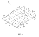
- FIG. 5A is a schematic diagram showing a super-hydrophobic microstructure 2a which is another aspect of the present invention.
- the base body 21 a of the super-hydrophobic microstructure 2a further includes at least a third protrusion 223a.
- the base body 21a includes a plurality of third protrusions 223a.
- the third protrusion 223a is disposed between two second protrusions 222, and the two ends of the third protrusion 223a are connected with the first protrusions 221.
- the third protrusion 223a has a third height H3, which is smaller than the second height H2 of the second protrusion 222.
- the third protrusion 223a is disposed between two second protrusions 222 and connected with the first protrusions 221. As viewing from the top, two first protrusions 221, one second protrusion 222 and one third protrusion 223a form another closed curve Sa. In other embodiment, the first protrusions 221 and the third protrusions 223a may form another closed curve; the second protrusions 222 and the third protrusions 223a may form another closed curve; otherwise, at least one first protrusion 221, at least one second protrusion 222 and at least one third protrusion 223a may form another closed curve.
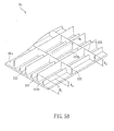
- FIG. 5B is a schematic diagram showing a super-hydrophobic microstructure 2b which is another aspect of the present invention.
- each third protrusion 223a is disposed between two first protrusions 221, and two ends of the third protrusion 223a are connected with the second protrusions 222.
- one first protrusion 221, two second protrusions 222 and one third protrusion 223b form another closed curve Sb.
- FIG. 5C is a schematic diagram showing a super-hydrophobic microstructure 2c which is another aspect of the present invention.
- the difference between the super-hydrophobic microstructures 2c and 2b is in that two second protrusions 222c are disposed between adjacent two first protrusions 221, two ends of one third protrusion 223c are connected with the first protrusion 221 and the second protrusion 222c, respectively, and the two ends of another third protrusion 223c are connected with two second protrusions 222c.
- two second protrusions 222c and two third protrusions 223c form another closed curve Sc
- a first protrusion 221, a second protrusion 222c and two third protrusions 223c form another closed curve Sc.
- the super-hydrophobic structure of the present invention has a base body configured with a plurality of protrusions with different heights, which form a closed curve as viewing from the top view. Accordingly, when a water droplet falls from a high point to the super-hydrophobic microstructure, the closed space formed by the water droplet and the protrusions can provide an air spring effect to bounce the water droplet away. Thus, the water droplet can not stay on the surface of the base body so as to achieve the super-hydrophobic effect of the invention. Besides, the protrusions with different heights can disperse the impact of the falling water droplet, so that the super-hydrophobic effect can be further enhanced.
- the base body of the super-hydrophobic microstructure has the protrusions with different heights and the protrusions are connected, so that the mold for the imprinting process does not have the isolated holes.
- the air contained inside the mold can be totally pushed out so as to fabricate the precise super-hydrophobic microstructure.
- this manufacturing method is suitable for mass production and can decrease the manufacturing cost.
- the protrusions with different heights are connected and form a closed curve, the structural strength of the super-hydrophobic microstructure can be improved.
- the protrusions with different heights can form multiple layers of closed spaces, so that it can provide multilayer air spring effect, which can further enhance the super-hydrophobic effect.
Landscapes
- Engineering & Computer Science (AREA)
- Nanotechnology (AREA)
- Chemical & Material Sciences (AREA)
- Crystallography & Structural Chemistry (AREA)
- Physics & Mathematics (AREA)
- Theoretical Computer Science (AREA)
- Mathematical Physics (AREA)
- Condensed Matter Physics & Semiconductors (AREA)
- General Physics & Mathematics (AREA)
- Manufacturing & Machinery (AREA)
- Laminated Bodies (AREA)
- Toys (AREA)
- Artificial Fish Reefs (AREA)
Applications Claiming Priority (1)
| Application Number | Priority Date | Filing Date | Title |
|---|---|---|---|
| TW100100970A TWI481545B (zh) | 2011-01-11 | 2011-01-11 | 超疏水性微結構 |
Publications (2)
| Publication Number | Publication Date |
|---|---|
| EP2474372A2 true EP2474372A2 (fr) | 2012-07-11 |
| EP2474372A3 EP2474372A3 (fr) | 2013-05-29 |
Family
ID=45507473
Family Applications (1)
| Application Number | Title | Priority Date | Filing Date |
|---|---|---|---|
| EP12150561.4A Withdrawn EP2474372A3 (fr) | 2011-01-11 | 2012-01-10 | Microstructure super hydrophobe |
Country Status (4)
| Country | Link |
|---|---|
| US (1) | US20120177881A1 (fr) |
| EP (1) | EP2474372A3 (fr) |
| CN (1) | CN102583214A (fr) |
| TW (1) | TWI481545B (fr) |
Cited By (5)
| Publication number | Priority date | Publication date | Assignee | Title |
|---|---|---|---|---|
| CN104897760A (zh) * | 2014-03-05 | 2015-09-09 | 中强光电股份有限公司 | 亲水膜片及其制造方法以及具有亲水膜片的生物感测器 |
| ES2725999A1 (es) * | 2018-03-28 | 2019-10-01 | Bsh Electrodomesticos Espana Sa | Cuerpo de polimero termoplastico con una estructura superficial, proceso para su fabricacion, y aparato domestico que comprende el cuerpo de polimero termoplastico |
| WO2020247434A1 (fr) * | 2019-06-04 | 2020-12-10 | Massachusetts Institute Of Technology | Procédés de redirection de gouttelettes, et systèmes et utilisations associés |
| EP3996151A1 (fr) | 2020-11-09 | 2022-05-11 | Adam Podgorski | Structure d'appoint pour une cellule photovoltaïque |
| US20220395859A1 (en) * | 2019-10-29 | 2022-12-15 | Kyocera Corporation | Coating film, automobile, and coating method |
Families Citing this family (21)
| Publication number | Priority date | Publication date | Assignee | Title |
|---|---|---|---|---|
| KR20120113532A (ko) * | 2011-04-05 | 2012-10-15 | 삼성전자주식회사 | 초소수성 구조물 |
| KR101866501B1 (ko) | 2011-09-28 | 2018-06-12 | 삼성전자주식회사 | 초소수성 전자기장 차폐재 및 그 제조방법 |
| NL2015033A (en) | 2014-07-25 | 2016-06-27 | Asml Netherlands Bv | An Immersion Lithographic Apparatus, and a Device Manufacturing Method. |
| US10907262B2 (en) | 2014-10-20 | 2021-02-02 | Ecole Polytechnique Federale De Lausanne (Epfl) | Membrane-less electrolyzer |
| CN106892577B (zh) * | 2015-12-21 | 2020-05-19 | 法国圣戈班玻璃公司 | 疏水组件及其形成方法、车窗 |
| CN107285272A (zh) * | 2016-03-30 | 2017-10-24 | 李森墉 | 兼具莲花与补光效应的多功能微结构 |
| CN106702725A (zh) * | 2016-11-30 | 2017-05-24 | 北京赛特超润界面科技有限公司 | 一种超疏水功能材料及其制备方法 |
| US11326138B2 (en) | 2017-05-01 | 2022-05-10 | University Of Kentucky Research Foundation | Cell culture device and methods of use thereof |
| CN107032284B (zh) * | 2017-05-04 | 2018-12-28 | 北京航空航天大学 | 一种仿瓶子草液膜快速搬运表面织构 |
| CN109959980B (zh) * | 2017-12-26 | 2020-09-08 | 清华大学 | 疏水镜子以及使用该疏水镜子的汽车 |
| CN109955785A (zh) * | 2017-12-26 | 2019-07-02 | 清华大学 | 疏水镜子以及使用该疏水镜子的汽车 |
| CN109958380B (zh) * | 2017-12-26 | 2021-04-02 | 清华大学 | 疏水窗户以及使用该疏水窗户的房子和汽车 |
| CN109957345B (zh) * | 2017-12-26 | 2020-09-25 | 清华大学 | 疏水膜 |
| CN109957131B (zh) * | 2017-12-26 | 2020-09-29 | 清华大学 | 疏水膜 |
| CN109958379B (zh) | 2017-12-26 | 2021-01-05 | 清华大学 | 疏水窗户以及使用该疏水窗户的房子和汽车 |
| CN110054799B (zh) * | 2019-05-07 | 2021-03-26 | 大连理工大学 | 一种可实现液滴饼状弹跳功能的超疏水半球阵列 |
| SE544449C2 (en) | 2019-12-23 | 2022-05-31 | Stora Enso Oyj | Method for manufacture of a patterned liquid repellent nanocellulosic film |
| KR102924991B1 (ko) * | 2020-05-07 | 2026-02-06 | 한국전기연구원 | 나노패턴을 갖는 투명 소수성 필름 제조방법 |
| DE202023000325U1 (de) | 2023-02-13 | 2024-05-17 | IMOS Gubela Gesellschaft mit beschränkter Haftung | Superhydrophobe modulare Struktur |
| EP4414092A1 (fr) | 2023-02-13 | 2024-08-14 | IMOS Gubela GmbH | Élément de microstructure modulaire |
| CN119551628A (zh) * | 2024-11-07 | 2025-03-04 | 同济大学 | 一种具备多层级微纳结构的疏水表面 |
Family Cites Families (7)
| Publication number | Priority date | Publication date | Assignee | Title |
|---|---|---|---|---|
| CN1323025C (zh) * | 2005-11-22 | 2007-06-27 | 华中科技大学 | 具有双微观结构的超疏水表面的制作方法 |
| US9134471B2 (en) * | 2006-06-28 | 2015-09-15 | 3M Innovative Properties Company | Oriented polymeric articles and method |
| KR101033273B1 (ko) * | 2008-03-27 | 2011-05-09 | 서울대학교산학협력단 | 초소수성 폴리머 구조물의 제조 |
| US20100112286A1 (en) * | 2008-11-03 | 2010-05-06 | Bahadur Vaibhav A | Superhydrophobic surfaces |
| CN102387915A (zh) * | 2009-02-17 | 2012-03-21 | 伊利诺伊大学评议会 | 柔性微结构超疏水材料 |
| CN101817500B (zh) * | 2010-03-24 | 2014-04-09 | 江苏大学 | 亲水材料表面超疏水功能转换的微结构设计和方法 |
| US9085019B2 (en) * | 2010-10-28 | 2015-07-21 | 3M Innovative Properties Company | Superhydrophobic films |
-
2011
- 2011-01-11 TW TW100100970A patent/TWI481545B/zh not_active IP Right Cessation
- 2011-11-18 CN CN2011103693484A patent/CN102583214A/zh active Pending
-
2012
- 2012-01-10 US US13/347,113 patent/US20120177881A1/en not_active Abandoned
- 2012-01-10 EP EP12150561.4A patent/EP2474372A3/fr not_active Withdrawn
Non-Patent Citations (1)
| Title |
|---|
| None |
Cited By (5)
| Publication number | Priority date | Publication date | Assignee | Title |
|---|---|---|---|---|
| CN104897760A (zh) * | 2014-03-05 | 2015-09-09 | 中强光电股份有限公司 | 亲水膜片及其制造方法以及具有亲水膜片的生物感测器 |
| ES2725999A1 (es) * | 2018-03-28 | 2019-10-01 | Bsh Electrodomesticos Espana Sa | Cuerpo de polimero termoplastico con una estructura superficial, proceso para su fabricacion, y aparato domestico que comprende el cuerpo de polimero termoplastico |
| WO2020247434A1 (fr) * | 2019-06-04 | 2020-12-10 | Massachusetts Institute Of Technology | Procédés de redirection de gouttelettes, et systèmes et utilisations associés |
| US20220395859A1 (en) * | 2019-10-29 | 2022-12-15 | Kyocera Corporation | Coating film, automobile, and coating method |
| EP3996151A1 (fr) | 2020-11-09 | 2022-05-11 | Adam Podgorski | Structure d'appoint pour une cellule photovoltaïque |
Also Published As
| Publication number | Publication date |
|---|---|
| US20120177881A1 (en) | 2012-07-12 |
| TW201228922A (en) | 2012-07-16 |
| EP2474372A3 (fr) | 2013-05-29 |
| TWI481545B (zh) | 2015-04-21 |
| CN102583214A (zh) | 2012-07-18 |
Similar Documents
| Publication | Publication Date | Title |
|---|---|---|
| EP2474372A2 (fr) | Microstructure super hydrophobe | |
| TWI296862B (en) | Polymeric matrix substrate | |
| US8137751B2 (en) | Hierarchical structures for superhydrophobic surfaces and methods of making | |
| KR101456504B1 (ko) | 기판 표면의 젖음성 개질방법 | |
| KR101966263B1 (ko) | 고압 안정성, 광학 투과도 및 자가 회복 특징을 갖는 미끄러운 표면 | |
| US20110300345A1 (en) | Surface Having Superhydrophobic Region And Superhydrophilic Region | |
| AU2020202234A1 (en) | Polymer membranes having open through holes, and method of fabrication thereof | |
| Yeo et al. | Robust hydrophobic surfaces with various micropillar arrays | |
| KR20160118213A (ko) | 나노 구조화된 표면을 갖는 제조 물품 | |
| US20160207083A1 (en) | Liquid-repellent surfaces made of any materials | |
| AU2011282218A1 (en) | Hierarchically structured surfaces to control wetting characteristics | |
| JP2013543990A (ja) | 超疎水性フィルム構造体 | |
| KR20110139228A (ko) | 플렉서블 마이크로구조화 초소수성 재료 | |
| WO2016122959A2 (fr) | Procédé de fabrication de microstructures rentrantes | |
| EP3642153B1 (fr) | Article transparent nanostructuré aux propriétés à la fois hydrophobes et antibuée, et procédés de fabrication | |
| KR20060003006A (ko) | 울트라포빅 표면을 갖는 캐리어 | |
| KR102559210B1 (ko) | 흡인을 갖는 패터닝된 표면 | |
| US20170282127A1 (en) | Etching mask, manufacturing method therefor, porous membrane manufacturing method using etching mask, porous membrane, fine dust-blocking mask including porous membrane, and manufacturing method for surface enhanced raman scattering active substrate | |
| JP2005525923A (ja) | 表面 | |
| KR20190027144A (ko) | 저응착을 위한 표면 패턴 구조를 갖는 초발수 필름 및 이의 제조 방법 | |
| Park et al. | Multifunctional micro/nanostructured interfaces, fabrication technologies, wetting control, and future prospects | |
| US20220088836A1 (en) | A component for liquid handling with self-cleaning properties | |
| KR101669734B1 (ko) | 초소수성 시트 및 이의 제조 방법 | |
| EP1553049A3 (fr) | Procédé de fabrication des structures micro-mécaniques par moulage | |
| KR102452838B1 (ko) | 수분 포집 및 제거 장치 |
Legal Events
| Date | Code | Title | Description |
|---|---|---|---|
| PUAI | Public reference made under article 153(3) epc to a published international application that has entered the european phase |
Free format text: ORIGINAL CODE: 0009012 |
|
| AK | Designated contracting states |
Kind code of ref document: A2 Designated state(s): AL AT BE BG CH CY CZ DE DK EE ES FI FR GB GR HR HU IE IS IT LI LT LU LV MC MK MT NL NO PL PT RO RS SE SI SK SM TR |
|
| AX | Request for extension of the european patent |
Extension state: BA ME |
|
| PUAL | Search report despatched |
Free format text: ORIGINAL CODE: 0009013 |
|
| AK | Designated contracting states |
Kind code of ref document: A3 Designated state(s): AL AT BE BG CH CY CZ DE DK EE ES FI FR GB GR HR HU IE IS IT LI LT LU LV MC MK MT NL NO PL PT RO RS SE SI SK SM TR |
|
| AX | Request for extension of the european patent |
Extension state: BA ME |
|
| RIC1 | Information provided on ipc code assigned before grant |
Ipc: B08B 17/06 20060101AFI20130425BHEP Ipc: G03F 7/00 20060101ALI20130425BHEP |
|
| 17P | Request for examination filed |
Effective date: 20131127 |
|
| RBV | Designated contracting states (corrected) |
Designated state(s): AL AT BE BG CH CY CZ DE DK EE ES FI FR GB GR HR HU IE IS IT LI LT LU LV MC MK MT NL NO PL PT RO RS SE SI SK SM TR |
|
| STAA | Information on the status of an ep patent application or granted ep patent |
Free format text: STATUS: THE APPLICATION IS DEEMED TO BE WITHDRAWN |
|
| 18D | Application deemed to be withdrawn |
Effective date: 20150801 |