EP4414092A1 - Élément de microstructure modulaire - Google Patents
Élément de microstructure modulaire Download PDFInfo
- Publication number
- EP4414092A1 EP4414092A1 EP24401006.2A EP24401006A EP4414092A1 EP 4414092 A1 EP4414092 A1 EP 4414092A1 EP 24401006 A EP24401006 A EP 24401006A EP 4414092 A1 EP4414092 A1 EP 4414092A1
- Authority
- EP
- European Patent Office
- Prior art keywords
- elements
- component
- main extension
- microstructure elements
- extension plane
- Prior art date
- Legal status (The legal status is an assumption and is not a legal conclusion. Google has not performed a legal analysis and makes no representation as to the accuracy of the status listed.)
- Pending
Links
- 238000004519 manufacturing process Methods 0.000 claims abstract description 12
- 239000007788 liquid Substances 0.000 claims description 11
- 238000006116 polymerization reaction Methods 0.000 claims description 11
- 238000004049 embossing Methods 0.000 claims description 8
- 238000000034 method Methods 0.000 claims description 8
- 239000000463 material Substances 0.000 claims description 4
- 238000000465 moulding Methods 0.000 claims description 3
- 239000000758 substrate Substances 0.000 claims description 3
- -1 ACRYLIC Substances 0.000 claims description 2
- 239000004696 Poly ether ether ketone Substances 0.000 claims description 2
- JUPQTSLXMOCDHR-UHFFFAOYSA-N benzene-1,4-diol;bis(4-fluorophenyl)methanone Chemical compound OC1=CC=C(O)C=C1.C1=CC(F)=CC=C1C(=O)C1=CC=C(F)C=C1 JUPQTSLXMOCDHR-UHFFFAOYSA-N 0.000 claims description 2
- 238000000748 compression moulding Methods 0.000 claims description 2
- 229920001903 high density polyethylene Polymers 0.000 claims description 2
- 238000001746 injection moulding Methods 0.000 claims description 2
- 230000003287 optical effect Effects 0.000 claims description 2
- 229920003229 poly(methyl methacrylate) Polymers 0.000 claims description 2
- 229920002530 polyetherether ketone Polymers 0.000 claims description 2
- 239000004926 polymethyl methacrylate Substances 0.000 claims description 2
- 239000011347 resin Substances 0.000 claims description 2
- 229920005989 resin Polymers 0.000 claims description 2
- 239000002184 metal Substances 0.000 claims 1
- 230000003075 superhydrophobic effect Effects 0.000 abstract description 7
- 230000000694 effects Effects 0.000 description 12
- XLYOFNOQVPJJNP-UHFFFAOYSA-N water Substances O XLYOFNOQVPJJNP-UHFFFAOYSA-N 0.000 description 7
- 238000009736 wetting Methods 0.000 description 7
- 230000002209 hydrophobic effect Effects 0.000 description 5
- 238000004140 cleaning Methods 0.000 description 4
- 230000000737 periodic effect Effects 0.000 description 4
- 230000015572 biosynthetic process Effects 0.000 description 3
- 239000003595 mist Substances 0.000 description 3
- 239000000178 monomer Substances 0.000 description 3
- 239000002245 particle Substances 0.000 description 3
- LFQSCWFLJHTTHZ-UHFFFAOYSA-N Ethanol Chemical compound CCO LFQSCWFLJHTTHZ-UHFFFAOYSA-N 0.000 description 2
- 235000006508 Nelumbo nucifera Nutrition 0.000 description 2
- 240000002853 Nelumbo nucifera Species 0.000 description 2
- 235000006510 Nelumbo pentapetala Nutrition 0.000 description 2
- 238000009833 condensation Methods 0.000 description 2
- 230000005494 condensation Effects 0.000 description 2
- 238000010276 construction Methods 0.000 description 2
- 238000009826 distribution Methods 0.000 description 2
- 239000005871 repellent Substances 0.000 description 2
- 230000000717 retained effect Effects 0.000 description 2
- 238000010146 3D printing Methods 0.000 description 1
- 229920000297 Rayon Polymers 0.000 description 1
- 238000005452 bending Methods 0.000 description 1
- 239000011248 coating agent Substances 0.000 description 1
- 238000000576 coating method Methods 0.000 description 1
- 230000001427 coherent effect Effects 0.000 description 1
- 238000005520 cutting process Methods 0.000 description 1
- 230000006735 deficit Effects 0.000 description 1
- 230000001419 dependent effect Effects 0.000 description 1
- 230000005284 excitation Effects 0.000 description 1
- 230000005661 hydrophobic surface Effects 0.000 description 1
- 230000000977 initiatory effect Effects 0.000 description 1
- 238000001459 lithography Methods 0.000 description 1
- 238000001393 microlithography Methods 0.000 description 1
- 238000001127 nanoimprint lithography Methods 0.000 description 1
- 239000004033 plastic Substances 0.000 description 1
- 229920003023 plastic Polymers 0.000 description 1
- 229920000642 polymer Polymers 0.000 description 1
- 239000011148 porous material Substances 0.000 description 1
- 238000007639 printing Methods 0.000 description 1
- 239000002964 rayon Substances 0.000 description 1
- 239000007787 solid Substances 0.000 description 1
- 230000003595 spectral effect Effects 0.000 description 1
- 239000000126 substance Substances 0.000 description 1
- 238000013022 venting Methods 0.000 description 1
Images





Classifications
-
- B—PERFORMING OPERATIONS; TRANSPORTING
- B08—CLEANING
- B08B—CLEANING IN GENERAL; PREVENTION OF FOULING IN GENERAL
- B08B17/00—Methods preventing fouling
- B08B17/02—Preventing deposition of fouling or of dust
- B08B17/06—Preventing deposition of fouling or of dust by giving articles subject to fouling a special shape or arrangement
- B08B17/065—Preventing deposition of fouling or of dust by giving articles subject to fouling a special shape or arrangement the surface having a microscopic surface pattern to achieve the same effect as a lotus flower
Definitions
- EP 2 636 501 B1 (Owner: Mitsubishi Rayon Co Ltd., priority date: 26 May 2011 ) presents a roll-to-roll molding and curing process for microstructured objects.
- EP 2 636 501 B1 (Owner: Mitsubishi Rayon Co Ltd., priority date: 26 May 2011 ) presents a roll-to-roll molding and curing process for microstructured objects.
- US 2007/0259156 A1 (inventor: Roger Kempers et. al., filing date: May 3, 2006 ) a 3-D printing process is proposed, especially for randomly distributed distances.
- a self-cleaning effect can be achieved by the beading of large liquid drops, and on the other hand, the formation of condensation and mist on surfaces with microstructures can be avoided in order to prevent fogging and the impairment of visibility through the treated surfaces or in reflection from them.
- the invention is based on the object of creating a superhydrophobic structure which can be easily produced by mass production, which is easy to demold, which is easy to replicate and which has a modular structure.
- Hydrophobic structures form a wetting angle of greater than 90° with a water droplet. Structures on which a water droplet forms a wetting angle of greater than 105° are defined as superhydrophobic.
- the wetting angle is the angle that the surface of a liquid droplet forms with the surface of a solid. The volume of the droplet filled with liquid is included in the wetting angle.
- a component according to the invention has a base body.
- the base body can be, for example, a film, a transparent and/or a reflective object.
- the base body is preferably approximately flat. This means that an extension of the base body in one spatial direction is at least a factor of 5 smaller than an extension in the other two spatial directions.
- the two Spatial directions in which the extension of the base body is greatest span a main extension plane.
- main extension plane refers to the unrolled flat state.
- the z-direction is considered to be the direction perpendicular to the main extension plane.
- a zero point of the z-axis is the minimum of all intersection edges of the microstructure elements with the base body.
- microstructure elements rise from the base body perpendicular to the main extension plane or alternatively form depressions in the base body. These microstructure elements increase the contact angle with a liquid drop, in particular with a water drop, and thus give the component according to the invention superhydrophobic properties.
- the microstructure elements are spatially separated from one another. They therefore do not form a coherent unit. With roundings, the component according to the invention can be produced more easily and in a stable form in a two-photon polymerization process, which is described below.
- the component is designed to be modular, i.e. several individual elements are put together as if according to the modular principle.
- the individual elements are therefore constructed in the same way and form the component according to the invention by being repeated multiple times in a row.
- the repeating individual elements are constructed as simply as possible.
- substructures of the microstructure elements can be dispensed with.
- the number of individual microstructure elements on an individual element can be limited.
- an individual element has fewer than fifteen individual microstructure elements, particularly preferably fewer than ten.
- This modular construction is also promoted by the fact that a repeating periodic function is selected to represent differences in the ends of the microstructure elements that are remote from the base body in the z direction.
- the different distances between the ends of the microstructure elements in the z direction increase the contact angle of the liquid drops, increase the water-repellent effect and reduce the contact area between the drops and the microstructure elements.
- the microstructure elements can take on one or more shapes, selected from the group of cylindrical or conical (truncated) structures or have the shape of a polygon extending perpendicular to the main plane of extension.
- the microstructure elements can have a constant diameter or a constant lateral dimension in their course perpendicular to the main plane of extension, or they can taper.
- Tapered structures have the advantage that they are easier to demold during embossing or injection-compression molding. Examples of these are cylindrical columns or pointed, pyramidal needles. With tapered structures, an even larger wetting angle is possible provided the surface tension of the drop is not destroyed. Structures in which the lateral dimension in the z direction is constant have greater stability. Cylindrical or conical structures are easier to produce due to the symmetry.
- Structures with a polygonal projection into the main plane of extension have the advantage that negative impressions look the same as positive shapes. This means that, unlike with cylindrical microstructure elements, elevations in the negative also become holes, but the checkerboard pattern is retained. This is particularly advantageous if a base area in the main plane of extension is to be divided exactly in half between the elevations of the microstructure elements and the valleys, which is then also retained in the negative.
- all microstructure elements have the same height, which is defined as the extension between the point of contact with the base body and the end remote from the base body, but due to a curvature or curvature of a surface of the base body, they end at a different height distance from the main extension plane, i.e. at a different point in the z-direction that runs perpendicular to the main extension plane.
- the curvature or curvature of the surface can be described as a periodic function. Examples of such functions are, in the simplest case, sinusoidal surfaces. Since, according to Fourier's theorem, all periodic functions can be represented as series of sine functions, and the limitations then lie in the production, harmonics are of course also included.
- microstructure elements are located at different phase positions of the curved surface.
- the change in the base body over the diameter of the microstructure element is neglected when measuring the height. In production, however, this is compensated for by the two-photon polymerization similar to 3D printing.
- different end points on a flat surface of the base body are defined by different heights of the Microstructure elements are achieved.
- This can be achieved, for example, by individually producing each individual microstructure element on the base body, for example by means of two-photon polymerization.
- the microstructure elements can be attached with a sinusoidal height distribution above the base body.
- the height of the microstructure elements differs by the phase position on the base body. The height therefore follows a periodic function, in particular a sine function. This can also be a function f(x,y) that repeats periodically in two spatial directions. If the wavelengths in the x and y directions are different, a preferred direction can be specified in which the liquid drops should roll off.
- the lateral dimension of the microstructure elements is between 2 ⁇ m and 10 ⁇ m.
- the lateral dimension is defined as the largest extension of a microstructure element in a plane coplanar to the main extension plane. Unless otherwise stated, the lateral dimension is the mean height of the cutting edge of the microstructure element with the surface of the base body.
- the term "lateral dimension" means the diameter, in the case of rectangular microstructure elements, the largest edge length.
- heights of the microstructure elements between 8 ⁇ m and 20 ⁇ m have proven to be suitable. Heights of around 10 ⁇ m are particularly suitable, which may vary by the amplitude of the periodically repeating function.
- the microstructure elements are spaced apart by between 1 and 30 ⁇ m, preferably between 8 and 15 ⁇ m, particularly preferably between 10 ⁇ m.
- the distance between two microstructure elements is defined as the shortest lateral distance along a vector that lies in the main plane of extension, for example along the x or y vector or along a linear combination thereof, between two edges that form the respective microstructure elements with the surface of the base body.
- a self-cleaning effect can be achieved at distances between 5 and 30 ⁇ m in that liquid droplets that run off and are directed to the edge of the component carry dirt particles with them.
- the distances between the microstructure elements vary according to one embodiment. This can be achieved, for example, by a predetermined mean distance and a predetermined standard deviation of the distance. The distances are then normally distributed and statistical.
- the distances between the microstructure elements can also have a gradient structure, for example, have larger values at one edge of the component than at an end further away from it. This allows water drops to be deflected in a targeted direction. Other targeted and defined distributions of the microstructure elements are also conceivable.
- Materials from which components according to the invention are manufactured include PMMA, ACRYLIC, PP, PE-HD or PEEK.
- a concrete example of the parameters of a component according to the invention is a sinusoidally curved base body with a wavelength of 30 ⁇ m and a curvature amplitude of 3 ⁇ m with columnar cylindrical microstructure elements that are arranged at a distance of 10 ⁇ m and have a constant diameter of 5 ⁇ m over the height.
- the difference between the height of two adjacent microstructure elements is up to 3 ⁇ m.
- Components according to the invention can be used, for example, as films, on optical elements, for example in road traffic or for shower cubicles or in humid environments.
- the invention provides for providing several individual elements, arranging the individual elements in a pattern and then assembling them.
- One possible method for producing the individual elements or a master for the individual elements that are to be replicated is two-photon lithography or two-photon polymerization. This takes advantage of the fact that very high intensities or a very high photon density are required to double the frequency of an excitation source, for example a laser in the visible or near-infrared spectral range. This photon density is only achieved in the focus of an ultra-short laser pulse in the femtosecond range. Instead of the resin hardening along the entire light path, it is possible for the hardening to be concentrated at a precise point. In the non-hardened areas, i.e. in the places where the necessary intensity to generate the resonance frequency of the photoinitiator, i.e.
- the uncured monomer is removed by rinsing with ethanol, for example. This makes it possible to form the microstructure elements at different heights with the required accuracy.
- Systems and monomers as well as photoinitiators for carrying out two-photon polymerization are commercially available.
- Both positive and negative forms can also be produced from individual elements produced by two-photon polymerization by means of metallic coating and single or multiple galvanic molding, from which individual elements can then be produced by means of embossing, injection molding or nanoimprinting processes.
- Roll-to-roll processes are also conceivable in which the individual elements are repeatedly applied to a roller and transferred in negative to a substrate, e.g. a film or its not yet cured monomers, but after initiation of polymerization.
- the transfer of the microstructures to a liquid substrate, i.e. to not yet cured polymers, can also be carried out using a fixed frame.
- the main extension plane is spanned by the vector of the roller or roll axis and a tangential vector on a support line of the roller.
- the main extension plane is thus virtually rolled up on the roller to form a main extension surface.
- the roller can be moved in a z-direction perpendicular to the main extension plane.
- the movement can be carried out by means of a linear motor.
- the movement can be carried out in such a way that an existing curvature is compensated.
- the movement of the roller can thus amplify height differences.
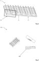
- FIG. 1 an individual element 13 of a component according to the invention is shown in two different views.
- the individual element 13 has a base body 3 with a surface 7 that is sinusoidally curved in one direction. Viewed from the macrostructure, the base body 3 is approximately flat.
- a main extension plane 11 can be defined, here for example the flat surface on a side of the base body 3 facing away from the curved surface 7.
- Several microstructure elements 5 are arranged on the base body at regular intervals 25 from one another. These intervals are, for example, 15 ⁇ m.
- this center line runs parallel to the main extension plane 11.
- the individual microstructure elements 5 run along a normal vector of this main extension plane 11.
- the microstructure elements 5 are arranged in a different phase position 17.
- the distances 21 of the end surfaces of the microstructure elements 5 from the main extension plane 11 differ by the difference 27.
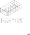
- Figure 2 shows how several individual elements 13 form a component 1 according to the invention.
- An individual element 13 is delimited in the frame.
- the base body 3 forms a seamless unit.
- the main extension plane 11 runs continuously.
- FIG 3 a negative impression of an individual element 113 according to the invention with a sinusoidally curved surface of the base body is shown. A drop of water is drained away at the points where material is present. The surface tension of the water prevents the liquid drop from flowing into the microstructure elements designed as pores.
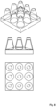
- Fig.4 shows an embodiment of an individual element 213 according to the invention with a flat base body 203 and rounded conical microstructure elements 205, the height 219 of which follows a sine function.
- This embodiment shows a self-cleaning effect, since the water drop is repelled from the surface and guided away from the surface of the component according to the invention over an edge 229 and takes dirt particles with it as a drop.
- the different heights and the rounding of the microstructure elements additionally increase the contact angle.
- Figure 5 is a negative impression of the individual element according to the invention from Figure 4 .
- FIG 6 an individual element 313 according to the invention is shown, in which the microstructure elements 305 are conical and are located on a sinusoidally curved surface 307 of the base body 303.
- the Figure 7 represented negative form to Figure 6 is particularly suitable for preventing the formation of fog, as any droplets that form are broken up.
- FIGS. 8 and 9 represent an embodiment of the invention in positive or negative impression, in which the surface of the base body is sinusoidally curved in two directions.
Applications Claiming Priority (2)
| Application Number | Priority Date | Filing Date | Title |
|---|---|---|---|
| DE202023000325.3U DE202023000325U1 (de) | 2023-02-13 | 2023-02-13 | Superhydrophobe modulare Struktur |
| DE102023001224.6A DE102023001224B3 (de) | 2023-02-13 | 2023-03-29 | Verfahren zur Herstellung einer modularen Struktur mit superhydrophoben Eigenschaften |
Publications (2)
| Publication Number | Publication Date |
|---|---|
| EP4414092A1 true EP4414092A1 (fr) | 2024-08-14 |
| EP4414092A8 EP4414092A8 (fr) | 2024-09-25 |
Family
ID=90236545
Family Applications (1)
| Application Number | Title | Priority Date | Filing Date |
|---|---|---|---|
| EP24401006.2A Pending EP4414092A1 (fr) | 2023-02-13 | 2024-02-09 | Élément de microstructure modulaire |
Country Status (1)
| Country | Link |
|---|---|
| EP (1) | EP4414092A1 (fr) |
Citations (14)
| Publication number | Priority date | Publication date | Assignee | Title |
|---|---|---|---|---|
| WO2006091235A1 (fr) * | 2004-07-27 | 2006-08-31 | Ut-Battelle, Llc | Materiau super-hydrophobe, nanostructure, composite |
| US20070259156A1 (en) | 2006-05-03 | 2007-11-08 | Lucent Technologies, Inc. | Hydrophobic surfaces and fabrication process |
| WO2012058605A1 (fr) * | 2010-10-28 | 2012-05-03 | 3M Innovative Properties Company | Surfaces modifiées pour la réduction de l'adhésion bactérienne |
| WO2012083011A1 (fr) * | 2010-12-15 | 2012-06-21 | Battelle Memorial Institute | Surface résistante aux salissures biologiques |
| US20120177881A1 (en) | 2011-01-11 | 2012-07-12 | Sen-Yung Lee | Super-hydrophobic microstructure |
| EP2636501B1 (fr) | 2011-05-26 | 2014-12-10 | Mitsubishi Rayon Co., Ltd. | Procédé de fabrication d'un article ayant une structure fine concavo-convexe sur sa surface |
| DE102014119470A1 (de) | 2014-12-22 | 2016-06-23 | Leibniz-Institut Für Neue Materialien Gemeinnützige Gmbh | Strukturierte Oberfläche mit stufenweise schaltbarer Adhäsion |
| US20170144202A1 (en) | 2009-02-17 | 2017-05-25 | The Board Of Trustees Of The University Of Illinois | Flexible Microstructured Superhydrophobic Materials |
| US20190133222A1 (en) | 2017-09-28 | 2019-05-09 | Bvw Holding Ag | Device for Dynamic Fluid Pinning |
| US20190212859A1 (en) | 2017-11-01 | 2019-07-11 | Bvw Holding Ag | Microstructured Phase Interfacial Device |
| WO2019186312A1 (fr) * | 2018-03-28 | 2019-10-03 | BSH Hausgeräte GmbH | Corps polymère thermoplastique doté d'une structure de surface, procédé pour sa fabrication et appareil électroménager comprenant le corps polymère thermoplastique |
| WO2020106945A1 (fr) * | 2018-11-21 | 2020-05-28 | Bvw Holding Ag | Surface microstructurée |
| US20210193856A1 (en) * | 2019-12-18 | 2021-06-24 | University Of Electronic Science And Technology Of China | Wear-resistant self-cleaning solar cell panel |
| WO2021215999A1 (fr) * | 2020-04-22 | 2021-10-28 | Agency For Science, Technology And Research | Procédé de fabrication de films superamphiphobes à microstructures doublement rentrantes |
-
2024
- 2024-02-09 EP EP24401006.2A patent/EP4414092A1/fr active Pending
Patent Citations (14)
| Publication number | Priority date | Publication date | Assignee | Title |
|---|---|---|---|---|
| WO2006091235A1 (fr) * | 2004-07-27 | 2006-08-31 | Ut-Battelle, Llc | Materiau super-hydrophobe, nanostructure, composite |
| US20070259156A1 (en) | 2006-05-03 | 2007-11-08 | Lucent Technologies, Inc. | Hydrophobic surfaces and fabrication process |
| US20170144202A1 (en) | 2009-02-17 | 2017-05-25 | The Board Of Trustees Of The University Of Illinois | Flexible Microstructured Superhydrophobic Materials |
| WO2012058605A1 (fr) * | 2010-10-28 | 2012-05-03 | 3M Innovative Properties Company | Surfaces modifiées pour la réduction de l'adhésion bactérienne |
| WO2012083011A1 (fr) * | 2010-12-15 | 2012-06-21 | Battelle Memorial Institute | Surface résistante aux salissures biologiques |
| US20120177881A1 (en) | 2011-01-11 | 2012-07-12 | Sen-Yung Lee | Super-hydrophobic microstructure |
| EP2636501B1 (fr) | 2011-05-26 | 2014-12-10 | Mitsubishi Rayon Co., Ltd. | Procédé de fabrication d'un article ayant une structure fine concavo-convexe sur sa surface |
| DE102014119470A1 (de) | 2014-12-22 | 2016-06-23 | Leibniz-Institut Für Neue Materialien Gemeinnützige Gmbh | Strukturierte Oberfläche mit stufenweise schaltbarer Adhäsion |
| US20190133222A1 (en) | 2017-09-28 | 2019-05-09 | Bvw Holding Ag | Device for Dynamic Fluid Pinning |
| US20190212859A1 (en) | 2017-11-01 | 2019-07-11 | Bvw Holding Ag | Microstructured Phase Interfacial Device |
| WO2019186312A1 (fr) * | 2018-03-28 | 2019-10-03 | BSH Hausgeräte GmbH | Corps polymère thermoplastique doté d'une structure de surface, procédé pour sa fabrication et appareil électroménager comprenant le corps polymère thermoplastique |
| WO2020106945A1 (fr) * | 2018-11-21 | 2020-05-28 | Bvw Holding Ag | Surface microstructurée |
| US20210193856A1 (en) * | 2019-12-18 | 2021-06-24 | University Of Electronic Science And Technology Of China | Wear-resistant self-cleaning solar cell panel |
| WO2021215999A1 (fr) * | 2020-04-22 | 2021-10-28 | Agency For Science, Technology And Research | Procédé de fabrication de films superamphiphobes à microstructures doublement rentrantes |
Non-Patent Citations (3)
| Title |
|---|
| JAFARI REZA ET AL: "Recent progress and challenges with 3D printing of patterned hydrophobic and superhydrophobic surfaces", THE INTERNATIONAL JOURNAL OF ADVANCED MANUFACTURING TECHNOLOGY, SPRINGER, LONDON, vol. 103, no. 1, 3 April 2019 (2019-04-03), pages 1225 - 1238, XP036828057, ISSN: 0268-3768, [retrieved on 20190403], DOI: 10.1007/S00170-019-03630-4 * |
| ROGER KEMPERS, ANMELDETAG, 3 May 2006 (2006-05-03) |
| VON ZHANG: "Lotus effect in wetting and self-cleaning", BIOTRIBOLOGY, vol. 5, March 2016 (2016-03-01), pages 31 - 43 |
Also Published As
| Publication number | Publication date |
|---|---|
| EP4414092A8 (fr) | 2024-09-25 |
Similar Documents
| Publication | Publication Date | Title |
|---|---|---|
| DE102004041434B4 (de) | Verfahren zur Herstellung eines Prägeblechs für eine Heiß-Kalt-Laminierpresse mit dreidimensionalen Strukturen | |
| DE10020877C1 (de) | Prägewerkzeug, Verfahren zum Herstellen desselben, Verfahren zur Strukturierung einer Oberfläche eines Werkstücks und Verwendung einer anodisch oxidierten Oberflächenschicht | |
| WO2017102443A1 (fr) | Procédé de fabrication d'un réseau de microlentilles | |
| WO2013182547A1 (fr) | Procédé de construction d'un moule en trois dimensions | |
| EP1063071A2 (fr) | Article en polymère avec une surface structurée, en particulier pneumatique, moule et fabrication du moule | |
| DE102023001224B3 (de) | Verfahren zur Herstellung einer modularen Struktur mit superhydrophoben Eigenschaften | |
| EP1476257A1 (fr) | Surface | |
| EP3774253B1 (fr) | Objet microstructuré | |
| EP1210221B1 (fr) | Procede pour la production d'une surface structuree | |
| DE4310296A1 (de) | Verfahren zum Herstellen gestufter Formeinsätze, gestufte Formeinsätze und damit abgeformte gestufte Mikrostrukturkörper hoher Präzision | |
| AT522535B1 (de) | Stempelreplikationsvorrichtung und Verfahren zum Herstellen einer Halteeinrichtung für eine Stempelreplikationsvorrichtung sowie eines Stempels | |
| DE19941048A1 (de) | Vorrichtung und Verfahren zur Erzeugung strukturierter Oberflächen mit erhöhter Resistenz gegen Verschmutzung und Benetzung | |
| EP3571038B1 (fr) | Système et procédé pour produire un objet tridimensionnel | |
| DE10330456B4 (de) | Vorrichtung zum Erstellen einer Oberflächenstruktur auf einem Wafer | |
| DE202009014165U1 (de) | Vorrichtung zum Spritzgießen von Kunststoffbauteilen und Verwendung dieser Vorrichtung sowie Spritzgießteile | |
| EP3083251B1 (fr) | Disposititif et procédé de production de surfaces structurées | |
| EP3517654B1 (fr) | Procédé de fabrication d'un insert de moule à (sous-)microstructures ainsi que pièce à usiner à (sous-)microstructures | |
| DE102020209106B4 (de) | Verfahren zum Bereitstellen eines Prägeelements für ein Prägewerkzeug, ein Prägeelement, eine Verwendung eines Prägeelements und ein Prägewerkzeug umfassend ein Prägeelement | |
| DE19602736A1 (de) | Verfahren und Vorrichtung zur Herstellung von optischen Linsen und optischen Linsenarrays | |
| AT516095B1 (de) | Vorrichtung zum Herstellen eines Linsenwafers | |
| DE10039208A1 (de) | Verfahren zur Herstellung eines Werkzeugs, das zur Schaffung optisch wirksamer Oberflächenstrukturen im sub-mum Bereich einsetzbar ist, sowie ein diesbezügliches Werkzeug | |
| WO2021001242A1 (fr) | Procédé pour produire un moule et moule utilisé pour produire un élément optique | |
| EP3311971B1 (fr) | Procédé pour la procution du part avec des structures superficielles | |
| DE102018106707A1 (de) | Verfahren zur Herstellung und Verwendung eines Substrats mit einer funktionalisierten Oberfläche | |
| DE102009019647B4 (de) | Beugungsgitter und Verfahren zur Herstellung |
Legal Events
| Date | Code | Title | Description |
|---|---|---|---|
| PUAI | Public reference made under article 153(3) epc to a published international application that has entered the european phase |
Free format text: ORIGINAL CODE: 0009012 |
|
| STAA | Information on the status of an ep patent application or granted ep patent |
Free format text: STATUS: THE APPLICATION HAS BEEN PUBLISHED |
|
| AK | Designated contracting states |
Kind code of ref document: A1 Designated state(s): AL AT BE BG CH CY CZ DE DK EE ES FI FR GB GR HR HU IE IS IT LI LT LU LV MC ME MK MT NL NO PL PT RO RS SE SI SK SM TR |
|
| RIN1 | Information on inventor provided before grant (corrected) |
Inventor name: GUBELA, MARIUS Inventor name: GUBELA, HANS-ERICH |
|
| STAA | Information on the status of an ep patent application or granted ep patent |
Free format text: STATUS: REQUEST FOR EXAMINATION WAS MADE |
|
| 17P | Request for examination filed |
Effective date: 20250206 |