EP2474380A1 - Procédé et dispositif de soudage destinés à déterminer la force du flux de soudage lors du soudage de dormants de récipient - Google Patents
Procédé et dispositif de soudage destinés à déterminer la force du flux de soudage lors du soudage de dormants de récipient Download PDFInfo
- Publication number
- EP2474380A1 EP2474380A1 EP12002254A EP12002254A EP2474380A1 EP 2474380 A1 EP2474380 A1 EP 2474380A1 EP 12002254 A EP12002254 A EP 12002254A EP 12002254 A EP12002254 A EP 12002254A EP 2474380 A1 EP2474380 A1 EP 2474380A1
- Authority
- EP
- European Patent Office
- Prior art keywords
- welding
- welding current
- current
- determined
- seam
- Prior art date
- Legal status (The legal status is an assumption and is not a legal conclusion. Google has not performed a legal analysis and makes no representation as to the accuracy of the status listed.)
- Withdrawn
Links
Images



Classifications
-
- B—PERFORMING OPERATIONS; TRANSPORTING
- B23—MACHINE TOOLS; METAL-WORKING NOT OTHERWISE PROVIDED FOR
- B23K—SOLDERING OR UNSOLDERING; WELDING; CLADDING OR PLATING BY SOLDERING OR WELDING; CUTTING BY APPLYING HEAT LOCALLY, e.g. FLAME CUTTING; WORKING BY LASER BEAM
- B23K11/00—Resistance welding; Severing by resistance heating
- B23K11/06—Resistance welding; Severing by resistance heating using roller electrodes
- B23K11/061—Resistance welding; Severing by resistance heating using roller electrodes for welding rectilinear seams
- B23K11/062—Resistance welding; Severing by resistance heating using roller electrodes for welding rectilinear seams for welding longitudinal seams of tubes
- B23K11/063—Lap welding
-
- B—PERFORMING OPERATIONS; TRANSPORTING
- B23—MACHINE TOOLS; METAL-WORKING NOT OTHERWISE PROVIDED FOR
- B23K—SOLDERING OR UNSOLDERING; WELDING; CLADDING OR PLATING BY SOLDERING OR WELDING; CUTTING BY APPLYING HEAT LOCALLY, e.g. FLAME CUTTING; WORKING BY LASER BEAM
- B23K11/00—Resistance welding; Severing by resistance heating
- B23K11/08—Seam welding not restricted to one of the preceding subgroups
- B23K11/087—Seam welding not restricted to one of the preceding subgroups for rectilinear seams
- B23K11/0873—Seam welding not restricted to one of the preceding subgroups for rectilinear seams of the longitudinal seam of tubes
- B23K11/0876—Lap welding
-
- B—PERFORMING OPERATIONS; TRANSPORTING
- B23—MACHINE TOOLS; METAL-WORKING NOT OTHERWISE PROVIDED FOR
- B23K—SOLDERING OR UNSOLDERING; WELDING; CLADDING OR PLATING BY SOLDERING OR WELDING; CUTTING BY APPLYING HEAT LOCALLY, e.g. FLAME CUTTING; WORKING BY LASER BEAM
- B23K11/00—Resistance welding; Severing by resistance heating
- B23K11/24—Electric supply or control circuits therefor
- B23K11/25—Monitoring devices
-
- B—PERFORMING OPERATIONS; TRANSPORTING
- B23—MACHINE TOOLS; METAL-WORKING NOT OTHERWISE PROVIDED FOR
- B23K—SOLDERING OR UNSOLDERING; WELDING; CLADDING OR PLATING BY SOLDERING OR WELDING; CUTTING BY APPLYING HEAT LOCALLY, e.g. FLAME CUTTING; WORKING BY LASER BEAM
- B23K31/00—Processes relevant to this subclass, specially adapted for particular articles or purposes, but not covered by any single one of main groups B23K1/00 - B23K28/00
- B23K31/12—Processes relevant to this subclass, specially adapted for particular articles or purposes, but not covered by any single one of main groups B23K1/00 - B23K28/00 relating to investigating the properties, e.g. the weldability, of materials
- B23K31/125—Weld quality monitoring
-
- B—PERFORMING OPERATIONS; TRANSPORTING
- B23—MACHINE TOOLS; METAL-WORKING NOT OTHERWISE PROVIDED FOR
- B23K—SOLDERING OR UNSOLDERING; WELDING; CLADDING OR PLATING BY SOLDERING OR WELDING; CUTTING BY APPLYING HEAT LOCALLY, e.g. FLAME CUTTING; WORKING BY LASER BEAM
- B23K2101/00—Articles made by soldering, welding or cutting
- B23K2101/04—Tubular or hollow articles
- B23K2101/12—Vessels
- B23K2101/125—Cans
Definitions
- the invention relates to a method for assessing the applied welding current during resistance seam welding of overlapping seams of successive container frames of a production series of container frames which have an overlapping width which changes along the seam. Furthermore, the invention relates to a welding device for the resistance seam welding of Be fiscalzargen comprising welding rollers, a welding current generator and a welding current control and a device for multiple detection along the weld seam of a container frame in this introduced electrical energy and / or for multiple detection of the temperature of the weld seam along a container frame the weld.
- the welding current intensity is set too high during the test welding, the welding takes place at too high a temperature and, in the welding area, craters and liquid frame or welding electrode material are deposited as "splashes” along the seam. This makes the frame useless for further use.
- the welding current is determined, which is used for the serial production of frames from this type of sheet.
- the welding current strength in the area between "gluing” and "splashes” is set approx. 2/3 distance from the too low value and thus approx. 1/3 distance from the too high value.
- the invention is based on the object to provide a better and thus generally faster and at least material-saving method for checking the welding current during the welding of the production series of Be dockerzargen. Furthermore, the invention is based on the object to provide a welding device for carrying out the method.
- the welding current used for the production series is in the thus determined preferred range or not or has the preferred value.
- a secure quality control can be carried out, which automatically runs without visual inspection and mechanical strength testing and allows a program-controlled traceable record for quality assurance.
- the welding current applied to the production series in the preferred range or target sub-range is within the preferred range, or has the exact preferred value, and if not, then also preferably automatically set by the controller, a new welding current value, which is then applied to the Be Daveerzargen the production series, which Follow the container frame welded to the falling or rising current.
- the object is achieved in that the welding current is changed during the welding of the seam of a container frame by the welding current control and / or the welding current generator and that can be determined by the device for multiple detection and the welding current control too hot welding and too cold welding is that results from the changing welding current.
- the assessment or testing of compliance with the optimal welding current intensity profile is carried out with the method explained above. This is done with this method (ie with decreasing or increasing welding current strength) on at least one frame, possibly on two or more frames, which have changing overlap, the optimum current value for the welding in the region of large and in the region of slight overlap determined by the introduced electrical welding energy along the seam and / or the temperature is measured several times along the seam.
- the welding current for the production is then selected as a generally ramped current waveform that combines these two current values.
- the invention also includes welding devices suitable for carrying out the method.
- FIG. 1 schematically shows a sequence of container frames 1 to 11 of a production series of Be fiscalerzargen.
- the container frames are in particular on a resistance welding machine according to FIG. 4 welded, from which in FIG. 1 only the welding rollers 21 and 22 are shown.
- the individual Be fiscalerzargen arrive as blanks from a round apparatus forth in the welding device and go through it in the direction of arrow d.
- the Be fiscalerzargenrohlinge 11 to 7 are thus in the schematic view of FIG. 1 not yet welded, the container frame 6 is being welded and the container frames 5 to 1 have already been welded.
- the welding of the series Be marierzargen 1 to 5 has been made in a known manner with a substantially constant welding current. Underneath the container frames, the course of the welding current over time is shown roughly schematically. The vertical axis represents the welding current in amperes (A), the horizontal axis the time t. It is shown that the series Be marierzargen 1 to 5 has been welded with a substantially constant welding current with the strength a1. This welding current has been determined prior to the start of production of the production series. This in a known manner, as mentioned above and in particular according to the procedure, as described in the European patent application no. 2 110 196 is described.
- the welding current is known to be an alternating current, which generates along the weld a large number of individual welding lenses, the together form the weld, which results in a tight weld of the longitudinal seam of the container frames. This is known and need not be explained here.
- the welding current in amperes is an essential aspect of whether the welding is done correctly or if too cold welding a "sticky" weld seam imperfect tightness is generated or if too hot welding a weld with "splashes" is generated , which is not useful for the further processing of the container frame.
- the procedure is as follows to judge whether or not the initially determined and adjusted current a1 produces a correct weld. This assessment is particularly useful for quality assurance or documentation of correct production, on the other hand for adjusting the welding current during production of the production series of Be dockerzargen, since the welding conditions can change during the production series.
- At least one container frame 6 is welded with a decreasing or increasing profile of the welding current intensity.
- This special welding can be done periodically after a predetermined number of container frames of the row, eg after 500 or after 1000 already welded container frames, or it can be done randomly after a random number of frames, or it is triggered by the operator.
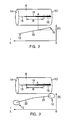
- the FIGS. 2 and 3 show two different variants, how this welding can be done with decreasing or increasing welding current.
- FIG. 2 and FIG. 3 shows in each case schematically the container frame 6 from the series of FIG. 1 with a plan view of the weld and below the frame 6 the course of the welding current over the welding time t or over the seam length L.
- the strength of the welding current during the welding of the frame 6 along the overlap weld seam is changed decreasing or increasing.
- the welding current strength 30 drops during the welding time or over the seam length and thus decreases from a high initial value to a low final value.
- the welding current is, as mentioned, in a known manner in Be psychologistzargenschweissen an alternating current, usually at a higher frequency than the mains voltage frequency, which is known in the art and will not be further explained here.
- the higher welding current is used at the beginning of the frame and the welding current 30 or its strength drops towards the end of the seam or towards the end 14 of the frame.
- a reverse procedure is also possible, in which a low welding current at the beginning 13 of the frame is started and the welding current strength increases along the seam. Then the area 15 would be at the beginning 13 of the frame and the splash area 16 at the end 14 of the frame. In between, a correct welding area 19 would again be formed.
- a container frame 6 can be formed in the production series, which covers the entire Welding current range of too high welding current up to low welding current in the seam of a frame 6 has.
- the procedure is to start with the high current, as in FIG. 2 is shown.
- FIG. 3 shows a further preferred embodiment, which is also in FIG. 1 is shown, the above explanations also apply here.
- Like reference numerals also designate like elements.
- it is not welded with a constant decreasing or increasing welding current strength 30, but with a current profile, which has at least two different slopes and corresponding to a break point (as shown) or more break points.
- FIG. 3 the two sections 31 and 32 of the current intensity curve over the seam length or welding time are shown. In the region of the higher current, the slope of the falling ramp is lower and in the region of the lower current 32, the slope is greater. It can thereby be achieved that the spatter boundary between the regions 16 and 19 is produced on the seam with a higher resolution.
- FIG. 4 schematically shows a resistance seam welding machine or seam welding machine 20, which has the two welding rollers 21 and 22, between which the seam of the container frames (shown as example the frame 5) is welded in a known manner.
- wire intermediate electrodes 26 and 27 can run.
- the lower welding roller 22 is mounted on a welding arm 29 and is supplied by the welding current generator 24 via the welding transformer 27 with the welding current.
- the welding current generator controls the application of the welding current to the upper welding roller 21. This is the person skilled in the art and will not be explained further here.
- a controller 23 may further control the welding current generator 24 and impose this periodically or randomly for the one frame 6 the desired ramp-shape of the welding current, which in this case is included in the control as a default value.
- the ramp-shaped course can also be stored in the welding current generator itself and be activated by an external signal for welding.
- a processor-controlled welding current generator which enables a procedure according to the invention, is a welding current generator of the type Pulsar or UNISOUD from Soudronic, Bergdietikon, Switzerland.
- the controller 23 may also determine the momentary current delivered to the welding rollers each current strength, either by measurement or by comparing the welding time or weld length with the current setpoint according to the ramp.
- FIG. 4 is shown as a variant that the lines from the controller 23 to the generator 24 in the opposite direction can deliver a current output signal of the generator to the controller 23.
- a separate current measuring device can be provided, which supplies the strength of the welding current to the controller.
- the electrical energy which is introduced into the weld seam and / or the temperature of the weld seam is measured, around the boundary of the too hot welded region 16 to the correctly welded region or to determine the boundary of the correctly welded region to the region 15 which is welded too cold on the basis of predetermined limit values for the energy or the temperature.
- a device 25 is shown schematically, which can determine the electrical welding energy several times during the welding of the container frame 6 and / or can determine the temperature of the weld seam.
- an IR thermometer 28 may be provided, which is connected to the device 25 or is a part thereof.
- the device 25 during the welding several times the voltage U between the welding electrodes and in particular between the welding rollers 21, 22 measure. Further, since the instantaneous welding current is known, the instantaneous energy can be determined. This may be done in the device 25 by the controller 23 providing the current value to the device 25 (or done by the welding current generator 24). Otherwise, the device 25 can supply the voltage value U to the controller 23 and this determines the electrical energy. The device 25 can also measure the welding current itself. A commercially available device 25 is in particular the "Weld Monitor" SWM-2 of Soudronic, Bergdietikon, Switzerland.
- This device 25 allows the electrical energy in each welding lens to be calculated by measuring the respective voltage drop between the welding rollers for each welding lens and taking into account the welding current for each welding lens. Furthermore, this device 25 or this "Weld Monitor" allows the heat radiation emanating from the weld seam to be sampled 2000 times per second.
- FIG. 5 shows the representation of part of the operating and display surface of this known device 25.
- the representation in the field 40 and the temperature of the weld with the representation in Box 50 can be explained, which is why the other parts or symbols of the operating and display surface of the "Weld Monitor" is not received, or they have been omitted in the figure.
- Panel 40 shows the detected electrical welding energy of each welding lens during welding a container frame.
- the curve 41 shows, for example, the welding of a container frame 1 to 5 with the constant welding current a1 of FIG. 1 .
- a region 42 is shown, which represents the empirically permissible range of energy and it is a region 43 can be seen in which the introduced into the weld electrical energy is too high or a region 44 in which the in the weld introduced electrical energy is too low.
- "spatters" would be produced in the region 43 on the weld seam and an "adhesive" weld seam would be produced in the region 44. There are thus limit values for the electrical energy, which separate these areas from each other.
- limit values are known to the person skilled in the art or stored in the device 25. It can be seen that the curve 41 for the frames 1 to 5 runs within the range 42 and is thus welded correctly with the adjusted welding current strength a1. The same finding results from the temperature measurement of the weld seam or the temperature curve 51, which moves within the permissible range 52 of the temperature and the range to high temperature 53 ("splash area”) or the area to low temperature 54 ("adhesive area”) reached. For this purpose too, corresponding limit values are known and stored in the device 25. The mentioned limit values may also be contained in the controller 23, so that it performs the comparison of the currently measured values for energy and temperature with the limit values. The display, if provided, takes place, as shown, with the device 25 and / or the display unit of the controller 23. The device 25 can thus also be completely replaced by the controller 23 by the controller 23 performing the functions mentioned.
- the curve 45 is then in Range 44 and the curve 55 is in the range 54.
- the energy measurement and / or the temperature measurement there are measured values which indicate whether the welding current intensity has a value that is too high or too low, if this value coincides with the limit values for the range transitions. 42 and 42-44, or with the range transitions 53-52 and 52-54, respectively.
- the range of welding current can be determined, in which a correctly welded weld is generated or the area 19 on the seam .
- a narrower range or value for the welding current can be assumed.
- a narrow range for the welding current can be judged to be a good range midway between the limits, or a desirable value can be assumed that divides the allowable range in the ratio 2/3 to 1/3 and closer to the splash limit is, as has been mentioned in the beginning as usual.
- This assessment based on the measurement of the welding of the individual container frame 6 allows it during the Production and without interruption of production to assess where the preferred current range is currently. This assessment can then be used in various ways.
- FIG. 1 is schematically visible. As stated, it has been welded with the current a1.
- the "Weld Monitor” could have been effective in determining a deviation for individual frames and at best withdrawing them from the production process. After a certain number of frames of the row (which is indicated by the frames 1-5), which number may be eg 500 or 1000 or 5000, then the welding of the individual frame with the falling (or rising) welding current strength (here the container frame 6).
- the controller that evaluates the measurements and then calculates the desired range or value may thus compare the original set value a1 with the range or value. If a1 is within the desired current range or at a predetermined distance from the desired value, the controller leaves the amperage for the welding of the following container frames 7 to 11 (or for the welding of the next 500 or 1000 or 5000 frames until again a single frame 6 is welded with falling (or rising) current) at the value a1.
- the controller determines that the value a1 is outside the desired range resulting from the measurement made during the welding of the frame 6 or too far away from the desired exact value the current is determined, which has resulted from the measurement during the welding of the frame 6, so the controller sets a new welding current a2, which is in the range or assumes the exact value. This is in FIG. 1 shown by now for the frames 7 to 11, the higher current a2 has been set.
- a1 is outside the desired range resulting from the measurement of the welding of the frame 6, or if it is too far away from the desired precise value of the current intensity resulting from the measurement in the case of Welding of the frame 6 has resulted, but the value a1 still leads to a curve 41 or 51 within the range 42 or 52, recorded only the deviation of a1 from the desired welding current to produce a quality assurance protocol.
- Both embodiments can also be combined, so that with slight deviations only recorded or logged and in addition, a new current value a2 is set at predetermined larger deviations.
- FIG. 6 is a corresponding frame shown schematically, at the beginning of the frame 13 at least in the area 35, the overlap is too large and at the end of the frame 14 at least in the area 36, the overlap is too small.
- the welding machine of FIG. 4 is with the controller 23 and the welding current generator 24 (which in turn is eg a welding current generator of the type Pulsar or UNISOUD the company Soudronic AG, Bergdietikon, Switzerland,) designed according to the second aspect of the invention, so that they quickly in series production for each frame consecutive frames produced a correspondingly decreasing or increasing welding current across the respective seam.
- the welding current generator 24 which in turn is eg a welding current generator of the type Pulsar or UNISOUD the company Soudronic AG, Bergdietikon, Switzerland, designed according to the second aspect of the invention, so that they quickly in series production for each frame consecutive frames produced a correspondingly decreasing or increasing welding current across the respective seam.
- a weld with changing welding current 31,32 is performed in a container frame 6 from the production series, which results in a changing weld seam, the welding of the excessively high temperature until the welding is too low.
- the electrical energy is repeatedly determined in this welding and / or repeatedly determined the temperature of the weld and based on the determined electrical energy values and / or the determined temperature values, from which welding current the welding of the individual container frame 6 too cold and from which welding current Hot welding has taken place and, by virtue of this determination, a preferred range of welding current intensity is determined within these limits. This can easily be done within the production, a judgment as to whether the welding current is correct.
- a changed welding current intensity can then be set if necessary, which is between the welding current strength of the too hot and too cold welding and is used for the following series of container frames of the production series. The same procedure is followed when welding container frames with non-uniform overlap.
Landscapes
- Engineering & Computer Science (AREA)
- Mechanical Engineering (AREA)
- Quality & Reliability (AREA)
- Resistance Welding (AREA)
- Lining Or Joining Of Plastics Or The Like (AREA)
Applications Claiming Priority (2)
| Application Number | Priority Date | Filing Date | Title |
|---|---|---|---|
| CH01027/09A CH701448B1 (de) | 2009-07-02 | 2009-07-02 | Verfahren und Schweissvorrichtung zur Beurteilung der angewandten Schweissstromstärke beim Widerstandsnahtschweissen von Behälterzargen. |
| EP10006228.0A EP2269760B1 (fr) | 2009-07-02 | 2010-06-16 | Procédé et dispositif de soudage destinés à déterminer la force du flux de soudage lors du soudage de dormants de récipient |
Related Parent Applications (2)
| Application Number | Title | Priority Date | Filing Date |
|---|---|---|---|
| EP10006228.0A Division-Into EP2269760B1 (fr) | 2009-07-02 | 2010-06-16 | Procédé et dispositif de soudage destinés à déterminer la force du flux de soudage lors du soudage de dormants de récipient |
| EP10006228.0 Division | 2010-06-16 |
Publications (1)
| Publication Number | Publication Date |
|---|---|
| EP2474380A1 true EP2474380A1 (fr) | 2012-07-11 |
Family
ID=42988419
Family Applications (2)
| Application Number | Title | Priority Date | Filing Date |
|---|---|---|---|
| EP12002254A Withdrawn EP2474380A1 (fr) | 2009-07-02 | 2010-06-16 | Procédé et dispositif de soudage destinés à déterminer la force du flux de soudage lors du soudage de dormants de récipient |
| EP10006228.0A Active EP2269760B1 (fr) | 2009-07-02 | 2010-06-16 | Procédé et dispositif de soudage destinés à déterminer la force du flux de soudage lors du soudage de dormants de récipient |
Family Applications After (1)
| Application Number | Title | Priority Date | Filing Date |
|---|---|---|---|
| EP10006228.0A Active EP2269760B1 (fr) | 2009-07-02 | 2010-06-16 | Procédé et dispositif de soudage destinés à déterminer la force du flux de soudage lors du soudage de dormants de récipient |
Country Status (6)
| Country | Link |
|---|---|
| US (1) | US8278583B2 (fr) |
| EP (2) | EP2474380A1 (fr) |
| CN (1) | CN101941117B (fr) |
| CH (1) | CH701448B1 (fr) |
| ES (1) | ES2795473T3 (fr) |
| PT (1) | PT2269760T (fr) |
Cited By (2)
| Publication number | Priority date | Publication date | Assignee | Title |
|---|---|---|---|---|
| CN110842392A (zh) * | 2019-11-26 | 2020-02-28 | 西安西电变压器有限责任公司 | 一种电弧焊质量缺陷位置预测方法 |
| CN115816082A (zh) * | 2022-11-28 | 2023-03-21 | 江苏骏业焊接技术有限公司 | 一种洗衣机内筒自动卷圆阻焊专机 |
Families Citing this family (46)
| Publication number | Priority date | Publication date | Assignee | Title |
|---|---|---|---|---|
| US9085044B2 (en) * | 2008-04-17 | 2015-07-21 | Soudronic Ag | Method and welding apparatus for the determination of the strength of the welding current to be used in the welding of container bodies |
| US9352411B2 (en) | 2008-05-28 | 2016-05-31 | Illinois Tool Works Inc. | Welding training system |
| US9101994B2 (en) | 2011-08-10 | 2015-08-11 | Illinois Tool Works Inc. | System and device for welding training |
| US9573215B2 (en) | 2012-02-10 | 2017-02-21 | Illinois Tool Works Inc. | Sound-based weld travel speed sensing system and method |
| CH707161A1 (de) * | 2012-11-06 | 2014-05-15 | Soudronic Ag | Verfahren und Vorrichtung zum Rollnahtschweissen von Behälterzargen. |
| US9368045B2 (en) | 2012-11-09 | 2016-06-14 | Illinois Tool Works Inc. | System and device for welding training |
| US9583014B2 (en) | 2012-11-09 | 2017-02-28 | Illinois Tool Works Inc. | System and device for welding training |
| US9713852B2 (en) | 2013-03-15 | 2017-07-25 | Illinois Tool Works Inc. | Welding training systems and devices |
| US9728103B2 (en) | 2013-03-15 | 2017-08-08 | Illinois Tool Works Inc. | Data storage and analysis for a welding training system |
| US9666100B2 (en) | 2013-03-15 | 2017-05-30 | Illinois Tool Works Inc. | Calibration devices for a welding training system |
| US9583023B2 (en) | 2013-03-15 | 2017-02-28 | Illinois Tool Works Inc. | Welding torch for a welding training system |
| US9672757B2 (en) | 2013-03-15 | 2017-06-06 | Illinois Tool Works Inc. | Multi-mode software and method for a welding training system |
| FIU20140168U1 (fi) * | 2013-05-29 | 2014-12-22 | Protomet Saerkiniemi T Mi | Hitsauksen säätölaite |
| US11090753B2 (en) | 2013-06-21 | 2021-08-17 | Illinois Tool Works Inc. | System and method for determining weld travel speed |
| US10056010B2 (en) | 2013-12-03 | 2018-08-21 | Illinois Tool Works Inc. | Systems and methods for a weld training system |
| US9724788B2 (en) | 2014-01-07 | 2017-08-08 | Illinois Tool Works Inc. | Electrical assemblies for a welding system |
| US10170019B2 (en) | 2014-01-07 | 2019-01-01 | Illinois Tool Works Inc. | Feedback from a welding torch of a welding system |
| US9751149B2 (en) | 2014-01-07 | 2017-09-05 | Illinois Tool Works Inc. | Welding stand for a welding system |
| US9757819B2 (en) | 2014-01-07 | 2017-09-12 | Illinois Tool Works Inc. | Calibration tool and method for a welding system |
| US10105782B2 (en) | 2014-01-07 | 2018-10-23 | Illinois Tool Works Inc. | Feedback from a welding torch of a welding system |
| US9589481B2 (en) | 2014-01-07 | 2017-03-07 | Illinois Tool Works Inc. | Welding software for detection and control of devices and for analysis of data |
| US9862049B2 (en) | 2014-06-27 | 2018-01-09 | Illinois Tool Works Inc. | System and method of welding system operator identification |
| US10307853B2 (en) | 2014-06-27 | 2019-06-04 | Illinois Tool Works Inc. | System and method for managing welding data |
| US9937578B2 (en) | 2014-06-27 | 2018-04-10 | Illinois Tool Works Inc. | System and method for remote welding training |
| US10665128B2 (en) | 2014-06-27 | 2020-05-26 | Illinois Tool Works Inc. | System and method of monitoring welding information |
| US9724787B2 (en) | 2014-08-07 | 2017-08-08 | Illinois Tool Works Inc. | System and method of monitoring a welding environment |
| US11014183B2 (en) | 2014-08-07 | 2021-05-25 | Illinois Tool Works Inc. | System and method of marking a welding workpiece |
| US9875665B2 (en) | 2014-08-18 | 2018-01-23 | Illinois Tool Works Inc. | Weld training system and method |
| US10239147B2 (en) | 2014-10-16 | 2019-03-26 | Illinois Tool Works Inc. | Sensor-based power controls for a welding system |
| US11247289B2 (en) | 2014-10-16 | 2022-02-15 | Illinois Tool Works Inc. | Remote power supply parameter adjustment |
| US10490098B2 (en) | 2014-11-05 | 2019-11-26 | Illinois Tool Works Inc. | System and method of recording multi-run data |
| US10210773B2 (en) | 2014-11-05 | 2019-02-19 | Illinois Tool Works Inc. | System and method for welding torch display |
| US10417934B2 (en) | 2014-11-05 | 2019-09-17 | Illinois Tool Works Inc. | System and method of reviewing weld data |
| US10402959B2 (en) | 2014-11-05 | 2019-09-03 | Illinois Tool Works Inc. | System and method of active torch marker control |
| US10204406B2 (en) | 2014-11-05 | 2019-02-12 | Illinois Tool Works Inc. | System and method of controlling welding system camera exposure and marker illumination |
| US10373304B2 (en) | 2014-11-05 | 2019-08-06 | Illinois Tool Works Inc. | System and method of arranging welding device markers |
| US10427239B2 (en) | 2015-04-02 | 2019-10-01 | Illinois Tool Works Inc. | Systems and methods for tracking weld training arc parameters |
| US10593230B2 (en) | 2015-08-12 | 2020-03-17 | Illinois Tool Works Inc. | Stick welding electrode holder systems and methods |
| US10657839B2 (en) | 2015-08-12 | 2020-05-19 | Illinois Tool Works Inc. | Stick welding electrode holders with real-time feedback features |
| US10438505B2 (en) | 2015-08-12 | 2019-10-08 | Illinois Tool Works | Welding training system interface |
| US10373517B2 (en) | 2015-08-12 | 2019-08-06 | Illinois Tool Works Inc. | Simulation stick welding electrode holder systems and methods |
| US11311958B1 (en) * | 2019-05-13 | 2022-04-26 | Airgas, Inc. | Digital welding and cutting efficiency analysis, process evaluation and response feedback system for process optimization |
| US11776423B2 (en) | 2019-07-22 | 2023-10-03 | Illinois Tool Works Inc. | Connection boxes for gas tungsten arc welding training systems |
| US11288978B2 (en) | 2019-07-22 | 2022-03-29 | Illinois Tool Works Inc. | Gas tungsten arc welding training systems |
| CN113579446A (zh) * | 2021-08-04 | 2021-11-02 | 公牛集团股份有限公司 | 焊接工艺 |
| JP7841496B2 (ja) * | 2023-07-21 | 2026-04-07 | Jfeスチール株式会社 | 薄鋼板のシーム溶接方法およびシーム溶接装置 |
Citations (3)
| Publication number | Priority date | Publication date | Assignee | Title |
|---|---|---|---|---|
| CH653786A5 (en) * | 1981-05-12 | 1986-01-15 | Elpatronic Ag | Method for the continuous monitoring of the quality of the welding seam and determination of welding defects in the resistance welding of can bodies |
| US5291423A (en) * | 1988-12-16 | 1994-03-01 | Elpatronic Ag | Arrangement for monitoring the quality of electric welds |
| EP2110196A2 (fr) | 2008-04-17 | 2009-10-21 | Soudronic AG | Procédé et dispositif de soudage destiné à déterminer le courant de soudage pour des joints de corps de boîte |
Family Cites Families (13)
| Publication number | Priority date | Publication date | Assignee | Title |
|---|---|---|---|---|
| US3586815A (en) * | 1969-03-26 | 1971-06-22 | Weltronic Co | Welding control mechanism |
| DE2010878C3 (de) * | 1970-03-07 | 1979-03-08 | Volkswagenwerk Ag, 3180 Wolfsburg | Verfahren zur Überwachung eines Widerstandspunk tschweißvorganges |
| US4447698A (en) * | 1973-03-06 | 1984-05-08 | Kelsey Hayes Company | Welding system monitoring and control system |
| DE3238766A1 (de) * | 1982-10-20 | 1984-04-26 | Hoesch Werke Ag | Verfahren und vorrichtung zur ueberwachung und/oder regelung des schweissstromes beim hochfrequenzwiderstandspressschweissen von laengsnahtrohren |
| US5064982A (en) * | 1983-06-10 | 1991-11-12 | Nippon Kokan Kabushiki Kaisha | Electric resistance seam welding method |
| JPS61216872A (ja) * | 1985-03-20 | 1986-09-26 | Dengensha Mfg Co Ltd | 溶接電流測定装置 |
| IT1206837B (it) * | 1987-01-09 | 1989-05-11 | Fiat Auto Spa | Procedimento e dispositivo per il controllo non distruttivo di puntidi saldatura di lamiera realizzati mediante saldatura elettrica |
| US4714816A (en) * | 1987-06-15 | 1987-12-22 | Cefin S.P.A. | Monitoring facility for electric welding equipment, in particular as used for metal box manufacture |
| CN1028077C (zh) * | 1991-03-06 | 1995-04-05 | 埃尔帕特朗尼股份公司 | 电阻焊接方法及实现该方法的装置 |
| DE59604358D1 (de) * | 1995-08-09 | 2000-03-09 | Elpatronic Ag | Schweissverfahren für beschichtetes Blech, insbesondere Weissblech |
| US5643479A (en) * | 1995-11-14 | 1997-07-01 | Lloyd; Robert D. | Electric arc welding |
| IT1310466B1 (it) * | 1999-09-08 | 2002-02-18 | Ada Applic Digitali E Analogic | Procedimento per il controllo di qualita' della saldatura a punti inmacchine saldatrici. |
| US7335853B2 (en) * | 2005-03-25 | 2008-02-26 | Mcgushion Kevin | Method for orbital welding using a pulsed current |
-
2009
- 2009-07-02 CH CH01027/09A patent/CH701448B1/de not_active IP Right Cessation
-
2010
- 2010-06-16 EP EP12002254A patent/EP2474380A1/fr not_active Withdrawn
- 2010-06-16 PT PT100062280T patent/PT2269760T/pt unknown
- 2010-06-16 ES ES10006228T patent/ES2795473T3/es active Active
- 2010-06-16 EP EP10006228.0A patent/EP2269760B1/fr active Active
- 2010-07-01 US US12/828,425 patent/US8278583B2/en active Active
- 2010-07-02 CN CN201010223369.0A patent/CN101941117B/zh not_active Expired - Fee Related
Patent Citations (4)
| Publication number | Priority date | Publication date | Assignee | Title |
|---|---|---|---|---|
| CH653786A5 (en) * | 1981-05-12 | 1986-01-15 | Elpatronic Ag | Method for the continuous monitoring of the quality of the welding seam and determination of welding defects in the resistance welding of can bodies |
| US5291423A (en) * | 1988-12-16 | 1994-03-01 | Elpatronic Ag | Arrangement for monitoring the quality of electric welds |
| EP2110196A2 (fr) | 2008-04-17 | 2009-10-21 | Soudronic AG | Procédé et dispositif de soudage destiné à déterminer le courant de soudage pour des joints de corps de boîte |
| EP2110197A2 (fr) | 2008-04-17 | 2009-10-21 | Soudronic AG | Procédé et dispositif de soudage destiné à déterminer le courant de soudage pour des joints de corps de boîte |
Cited By (3)
| Publication number | Priority date | Publication date | Assignee | Title |
|---|---|---|---|---|
| CN110842392A (zh) * | 2019-11-26 | 2020-02-28 | 西安西电变压器有限责任公司 | 一种电弧焊质量缺陷位置预测方法 |
| CN115816082A (zh) * | 2022-11-28 | 2023-03-21 | 江苏骏业焊接技术有限公司 | 一种洗衣机内筒自动卷圆阻焊专机 |
| CN115816082B (zh) * | 2022-11-28 | 2023-10-27 | 江苏骏业焊接技术有限公司 | 一种洗衣机内筒自动卷圆阻焊专机 |
Also Published As
| Publication number | Publication date |
|---|---|
| EP2269760B1 (fr) | 2020-03-25 |
| EP2269760A1 (fr) | 2011-01-05 |
| PT2269760T (pt) | 2020-06-01 |
| CN101941117A (zh) | 2011-01-12 |
| US8278583B2 (en) | 2012-10-02 |
| CH701448A2 (de) | 2011-01-14 |
| CN101941117B (zh) | 2014-07-30 |
| US20110000892A1 (en) | 2011-01-06 |
| CH701448B1 (de) | 2022-07-29 |
| ES2795473T3 (es) | 2020-11-23 |
Similar Documents
| Publication | Publication Date | Title |
|---|---|---|
| EP2269760B1 (fr) | Procédé et dispositif de soudage destinés à déterminer la force du flux de soudage lors du soudage de dormants de récipient | |
| EP0373422B1 (fr) | Appareil pour surveiller la qualité de soudures électriques | |
| WO2003011511A1 (fr) | Procede de soudage a l'arc de courte duree et systeme de soudage a l'arc de courte duree, permettant de detecter des defauts de haute frequence | |
| EP2243584B1 (fr) | Dispositif et procédé destinés à la fabrication de dormants de récipients en tôle métallique | |
| DE3711771C2 (fr) | ||
| EP2110197B1 (fr) | Procédé et dispositif de soudage destiné à déterminer le courant de soudage pour des joints de corps de boîte | |
| DE102008028385B4 (de) | Mess- und Steuerverfahren zum Widerstandsschweißen | |
| EP2916988B1 (fr) | Procédé et appareil pour le soudage à la molette de corps de boîte | |
| EP3554753B1 (fr) | Procédé et dispositif de soudage à la molette de corps de récipients | |
| DE2010878B2 (de) | Verfahren zur Überwachung eines Widers tandspunkischweilivorganges | |
| DE10328635B4 (de) | Verfahren und Vorrichtung zur Gewinnung von Informationen zur Beurteilung der Qualität einer Widerstandsschweißverbindung und/oder zur Steuerung oder Regelung eines Widerstandsschweißverfahrens | |
| EP3138652B1 (fr) | Procédé de soudure électrique | |
| DE10331617B4 (de) | Verfahren und Vorrichtung zur Erfassung und Überwachung der Eigenschaften von Komponenten oder Teilen im Sekundärstromkreis von Widerstandsschweißanlagen | |
| DE2346561C3 (de) | Verfahren zum Regeln elektrischer Widers tandsschweiBvorgänge | |
| EP1075892B1 (fr) | Méthode et appareil de mesure pour contrôler la qualité du soudage par pression ou par rouleaux de tôles assemblées | |
| DE19955691C2 (de) | Verfahren und Vorrichtung zum Widerstandsschweissen | |
| CH653786A5 (en) | Method for the continuous monitoring of the quality of the welding seam and determination of welding defects in the resistance welding of can bodies | |
| DE2149538B2 (de) | Verfahren zum kontinuierlichen elektrischen pressnahtschweissen von rohren | |
| DE102004054856B4 (de) | Verfahren und Vorrichtung zum Bestimmen des elektrischen Widerstands eines Metallflachprodukts | |
| DE19530416C2 (de) | Verfahren und Vorrichtung zum Erfassen und Auswerten eines Meßwertes während eines Schweißvorganges, insbesondere Bolzenschweißen mit Spitzenzündung | |
| EP1893998A1 (fr) | Cellule de mesure et procede execute avec ladite cellule pour determiner le degre de desagregation de cellules biologiques induit par electroporation | |
| DE102008030271A1 (de) | Vorrichtung und Verfahren zur Prüfung der Dichtigkeit von Verschlusskappen auf medizinischen Hohlkörpern | |
| EP1935549A2 (fr) | Dispositif et procédé de soudage par résistance | |
| DE102016220794A1 (de) | Vorrichtung und verfahren zur überwachung von ansteuerdaten eines schweisswerkzeugs | |
| CH704987A1 (de) | Schweissvorrichtung für das elektrische Rollnahtschweissen sowie Verfahren zum Rollnahtschweissen. |
Legal Events
| Date | Code | Title | Description |
|---|---|---|---|
| PUAI | Public reference made under article 153(3) epc to a published international application that has entered the european phase |
Free format text: ORIGINAL CODE: 0009012 |
|
| AC | Divisional application: reference to earlier application |
Ref document number: 2269760 Country of ref document: EP Kind code of ref document: P |
|
| AK | Designated contracting states |
Kind code of ref document: A1 Designated state(s): AL AT BE BG CH CY CZ DE DK EE ES FI FR GB GR HR HU IE IS IT LI LT LU LV MC MK MT NL NO PL PT RO SE SI SK SM TR |
|
| 17P | Request for examination filed |
Effective date: 20120813 |
|
| 17Q | First examination report despatched |
Effective date: 20160524 |
|
| STAA | Information on the status of an ep patent application or granted ep patent |
Free format text: STATUS: EXAMINATION IS IN PROGRESS |
|
| STAA | Information on the status of an ep patent application or granted ep patent |
Free format text: STATUS: THE APPLICATION IS DEEMED TO BE WITHDRAWN |
|
| 18D | Application deemed to be withdrawn |
Effective date: 20230610 |