EP2474422B1 - Dispositif de coupe et procédé de coupe de celui-ci - Google Patents
Dispositif de coupe et procédé de coupe de celui-ci Download PDFInfo
- Publication number
- EP2474422B1 EP2474422B1 EP10813448.7A EP10813448A EP2474422B1 EP 2474422 B1 EP2474422 B1 EP 2474422B1 EP 10813448 A EP10813448 A EP 10813448A EP 2474422 B1 EP2474422 B1 EP 2474422B1
- Authority
- EP
- European Patent Office
- Prior art keywords
- image
- cutting
- printed
- cutting process
- reference marks
- Prior art date
- Legal status (The legal status is an assumption and is not a legal conclusion. Google has not performed a legal analysis and makes no representation as to the accuracy of the status listed.)
- Not-in-force
Links
Images


Classifications
-
- B—PERFORMING OPERATIONS; TRANSPORTING
- B41—PRINTING; LINING MACHINES; TYPEWRITERS; STAMPS
- B41J—TYPEWRITERS; SELECTIVE PRINTING MECHANISMS, i.e. MECHANISMS PRINTING OTHERWISE THAN FROM A FORME; CORRECTION OF TYPOGRAPHICAL ERRORS
- B41J11/00—Devices or arrangements of selective printing mechanisms, e.g. ink-jet printers or thermal printers, for supporting or handling copy material in sheet or web form
- B41J11/66—Applications of cutting devices
- B41J11/68—Applications of cutting devices cutting parallel to the direction of paper feed
-
- B—PERFORMING OPERATIONS; TRANSPORTING
- B41—PRINTING; LINING MACHINES; TYPEWRITERS; STAMPS
- B41J—TYPEWRITERS; SELECTIVE PRINTING MECHANISMS, i.e. MECHANISMS PRINTING OTHERWISE THAN FROM A FORME; CORRECTION OF TYPOGRAPHICAL ERRORS
- B41J11/00—Devices or arrangements of selective printing mechanisms, e.g. ink-jet printers or thermal printers, for supporting or handling copy material in sheet or web form
- B41J11/66—Applications of cutting devices
- B41J11/70—Applications of cutting devices cutting perpendicular to the direction of paper feed
- B41J11/706—Applications of cutting devices cutting perpendicular to the direction of paper feed using a cutting tool mounted on a reciprocating carrier
-
- B—PERFORMING OPERATIONS; TRANSPORTING
- B26—HAND CUTTING TOOLS; CUTTING; SEVERING
- B26D—CUTTING; DETAILS COMMON TO MACHINES FOR PERFORATING, PUNCHING, CUTTING-OUT, STAMPING-OUT OR SEVERING
- B26D1/00—Cutting through work characterised by the nature or movement of the cutting member or particular materials not otherwise provided for; Apparatus or machines therefor; Cutting members therefor
- B26D1/01—Cutting through work characterised by the nature or movement of the cutting member or particular materials not otherwise provided for; Apparatus or machines therefor; Cutting members therefor involving a cutting member which does not travel with the work
- B26D1/04—Cutting through work characterised by the nature or movement of the cutting member or particular materials not otherwise provided for; Apparatus or machines therefor; Cutting members therefor involving a cutting member which does not travel with the work having a linearly-movable cutting member
- B26D1/045—Cutting through work characterised by the nature or movement of the cutting member or particular materials not otherwise provided for; Apparatus or machines therefor; Cutting members therefor involving a cutting member which does not travel with the work having a linearly-movable cutting member for thin material, e.g. for sheets, strips or the like
-
- B—PERFORMING OPERATIONS; TRANSPORTING
- B26—HAND CUTTING TOOLS; CUTTING; SEVERING
- B26D—CUTTING; DETAILS COMMON TO MACHINES FOR PERFORATING, PUNCHING, CUTTING-OUT, STAMPING-OUT OR SEVERING
- B26D5/00—Arrangements for operating and controlling machines or devices for cutting, cutting-out, stamping-out, punching, perforating, or severing by means other than cutting
-
- B—PERFORMING OPERATIONS; TRANSPORTING
- B26—HAND CUTTING TOOLS; CUTTING; SEVERING
- B26D—CUTTING; DETAILS COMMON TO MACHINES FOR PERFORATING, PUNCHING, CUTTING-OUT, STAMPING-OUT OR SEVERING
- B26D5/00—Arrangements for operating and controlling machines or devices for cutting, cutting-out, stamping-out, punching, perforating, or severing by means other than cutting
- B26D5/20—Arrangements for operating and controlling machines or devices for cutting, cutting-out, stamping-out, punching, perforating, or severing by means other than cutting with interrelated action between the cutting member and work feed
- B26D5/30—Arrangements for operating and controlling machines or devices for cutting, cutting-out, stamping-out, punching, perforating, or severing by means other than cutting with interrelated action between the cutting member and work feed having the cutting member controlled by scanning a record carrier
-
- B—PERFORMING OPERATIONS; TRANSPORTING
- B26—HAND CUTTING TOOLS; CUTTING; SEVERING
- B26D—CUTTING; DETAILS COMMON TO MACHINES FOR PERFORATING, PUNCHING, CUTTING-OUT, STAMPING-OUT OR SEVERING
- B26D5/00—Arrangements for operating and controlling machines or devices for cutting, cutting-out, stamping-out, punching, perforating, or severing by means other than cutting
- B26D5/20—Arrangements for operating and controlling machines or devices for cutting, cutting-out, stamping-out, punching, perforating, or severing by means other than cutting with interrelated action between the cutting member and work feed
- B26D5/30—Arrangements for operating and controlling machines or devices for cutting, cutting-out, stamping-out, punching, perforating, or severing by means other than cutting with interrelated action between the cutting member and work feed having the cutting member controlled by scanning a record carrier
- B26D5/34—Arrangements for operating and controlling machines or devices for cutting, cutting-out, stamping-out, punching, perforating, or severing by means other than cutting with interrelated action between the cutting member and work feed having the cutting member controlled by scanning a record carrier scanning being effected by a photosensitive device
-
- B—PERFORMING OPERATIONS; TRANSPORTING
- B41—PRINTING; LINING MACHINES; TYPEWRITERS; STAMPS
- B41J—TYPEWRITERS; SELECTIVE PRINTING MECHANISMS, i.e. MECHANISMS PRINTING OTHERWISE THAN FROM A FORME; CORRECTION OF TYPOGRAPHICAL ERRORS
- B41J11/00—Devices or arrangements of selective printing mechanisms, e.g. ink-jet printers or thermal printers, for supporting or handling copy material in sheet or web form
- B41J11/66—Applications of cutting devices
- B41J11/663—Controlling cutting, cutting resulting in special shapes of the cutting line, e.g. controlling cutting positions, e.g. for cutting in the immediate vicinity of a printed image
-
- B—PERFORMING OPERATIONS; TRANSPORTING
- B26—HAND CUTTING TOOLS; CUTTING; SEVERING
- B26D—CUTTING; DETAILS COMMON TO MACHINES FOR PERFORATING, PUNCHING, CUTTING-OUT, STAMPING-OUT OR SEVERING
- B26D5/00—Arrangements for operating and controlling machines or devices for cutting, cutting-out, stamping-out, punching, perforating, or severing by means other than cutting
- B26D5/20—Arrangements for operating and controlling machines or devices for cutting, cutting-out, stamping-out, punching, perforating, or severing by means other than cutting with interrelated action between the cutting member and work feed
- B26D5/30—Arrangements for operating and controlling machines or devices for cutting, cutting-out, stamping-out, punching, perforating, or severing by means other than cutting with interrelated action between the cutting member and work feed having the cutting member controlled by scanning a record carrier
- B26D5/32—Arrangements for operating and controlling machines or devices for cutting, cutting-out, stamping-out, punching, perforating, or severing by means other than cutting with interrelated action between the cutting member and work feed having the cutting member controlled by scanning a record carrier with the record carrier formed by the work itself
-
- B—PERFORMING OPERATIONS; TRANSPORTING
- B26—HAND CUTTING TOOLS; CUTTING; SEVERING
- B26F—PERFORATING; PUNCHING; CUTTING-OUT; STAMPING-OUT; SEVERING BY MEANS OTHER THAN CUTTING
- B26F1/00—Perforating; Punching; Cutting-out; Stamping-out; Apparatus therefor
- B26F1/38—Cutting-out; Stamping-out
- B26F1/3806—Cutting-out; Stamping-out wherein relative movements of tool head and work during cutting have a component tangential to the work surface
Definitions
- the present invention relates to a cutting device including a cutting head that performs a cutting process on a target medium, and to a cutting method using the cutting device.
- a device that performs a cutting process on a target medium by carrying out a combination of an operation moving a cutting head left to right and back again with respect to a target medium supported by a platen and an operation feeding the target medium front and back has been known as an example of the heretofore described kind of cutting device.
- a printer device configured so as to print an image on a surface of a target medium, using a printer head that ejects ink from an ejection nozzle instead of the cutting head.
- an image and, for example, four reference marks (hereafter called Trim marks) surrounding the image are printed using the printer head.
- Trim marks reference marks
- the printing is performed over the whole of a printing region of the target medium while feeding the target medium forward, and the target medium is rolled up into a roll form.
- the target medium rolled into a roll form is back-fed in a backward direction, and a portion of the target medium printed first (a print starting position) is positioned on the platen. Then, the position of a first reference mark, of the four reference marks corresponding to an image printed on a front end of the target medium, is detected using a Trim mark detection portion, the target medium is fed from front to back and the position of a second reference mark detected, the Trim mark detection portion is moved left to right and a third reference mark detected, and the target medium is fed from front to back again, and the position of a fourth reference mark detected.
- Patent Document 1 JP-A-2005-297248
- the heretofore described cutting device it is necessary to feed the target medium from front to back twice when detecting the positions of the reference marks corresponding to one image.
- the heretofore described back-feed it is necessary to feed the target medium from front to back three times before starting the cutting process. Because of this, for example, when printing an image that is long from front to back (for example, the front-back length is approximately 1m), and performing a cutting process along the outline of the image, it is necessary to feed the target medium a considerable distance (approximately 1m) twice from front to back when detecting the positions of the reference marks.
- misalignment is not liable to occur when detecting the positions of the reference marks, however, because the target medium is fed backward by being back-fed once before starting the cutting process, there is a problem in that misalignment is liable to occur at that time.
- the invention having been contrived bearing in mind the heretofore described problems, has an object of providing a cutting device, and a cutting method thereof, as defined in the appended claims, with which a cutting process is possible in a condition wherein positional accuracy of a cutting head and target medium is ensured.
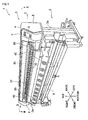
- FIG. 1 shows a perspective view of the cutting device 1
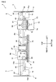
- Fig. 2 an internal configuration of a main body portion 3, to be described hereafter
- Fig. 3 a plan view of a unit drive device 80, to be described hereafter
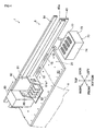
- Fig. 4 a perspective view of the periphery of a printing unit 60, to be described hereafter
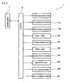
- Fig. 5 a control system diagram of a cutting device 1 respectively.
- the cutting device 1, as shown in Fig. 1 is mainly configured of a support portion 2 formed of a left-right pair of support legs 2a, 2a, and the main body portion 3 extending left to right supported by the support portion 2.
- a left main body portion 5 and a right main body portion 6 are formed respectively in left and right end portions of the main body portion 3, and external periphery portions thereof are covered by a main body cover 4.
- An operation portion 7 formed of operation switches, display devices, and the like, is provided on a front surface side of the left main body portion 5.
- a controller 9 into which an operation signal from the operation portion 7 is input is provided inside the left main body portion 5.
- the controller 9 is electrically connected to each component, to be described hereafter, and carries out an operation control by outputting an operation signal to each component. Specifically, as shown in Fig. 5 , the controller 9 controls a drive of a front-back drive motor, a drive of a left oscillating mechanism 11a, a drive of a right oscillating mechanism 13a, an up-down movement of a cutter holder 52, an ejection of ink from a printer head 62 (ejection nozzle), a drive of an up-down transfer mechanism 74, a drive of a left-right drive motor 83, a coupling by a first coupling mechanism 86, and a coupling by a second coupling mechanism 87, to be described hereafter. Also, a result of receiving an inspection light in a Trim mark detection portion 54, to be described hereafter, is input into the controller 9.
- the medium feeding mechanism 20, as shown in Fig. 4 is mainly configured of a rotatable plural pinch rollers 15 disposed so as to be aligned left to right in a lower portion of the guide member 40, and a feeding roller 16 provided so as to be exposed in the platen 30 under the pinch rollers 15.
- the feeding roller 16 is rotated by an unshown front-back drive motor.
- the cutting unit 50 is mainly configured of a cutting carriage 51, the cutter holder 52, and the Trim mark detection portion 54.
- the cutting carriage 51 is attached so as to be movable left and right to a guide rail 40a formed on a front surface side of the guide member 40, and forms an attachment base of the cutter holder 52 and Trim mark detection portion 54.
- an engagement portion (not shown) engageable with a right hook 14, to be described hereafter, is formed on a right surface of the cutting carriage 51.
- the cutter holder 52 is mounted so as to be movable up and down to the cutting carriage 51, and a cutter blade 53 is removably attached to a lower end portion of the cutter holder 52.
- the Trim mark detection portion 54 includes a light emitting portion (not shown) and a light receiving portion (not shown) on a, lower surface thereof. A configuration is such that reflected light of an inspection light projected in a downward direction from the light emitting portion is received by the light receiving portion.
- light receiving sensitivity of the light receiving portion is set in such a way that, while an inspection light (an inspection light with a high intensity) is reflected from a surface of the sheet member 8 on which no printing has been carried out, and received by the light receiving portion, the inspection light is not reflected (an inspection light with a low intensity is reflected) from portions in which Trim marks T1 to T4, to be described hereafter, are printed.
- the printing unit 60 is mainly configured of a printing carriage 61 and plural printer heads 62.
- the printing carriage 61 in the same way as the cutting carriage 51, is attached so as to be movable left and right to the guide rail 40a, and forms an attachment base of the printer heads 62.
- the plural printer heads 62 are configured of various colors, for example, magenta, yellow, cyan, and black.
- plural ejection nozzles (not shown) from which ink is ejected in a downward direction are formed on a lower surface of each printer head 62.
- the maintenance device 70 is provided inside the left main body portion 5.
- the maintenance device 70 is mainly configured of (four) suction caps 71 formed following the form of lower surfaces of the printer heads 62, a stage 72 on which the suction caps 71 are mounted, a device main body 73, and the up-down transfer mechanism 74 provided inside the device main body 73.
- the unit drive device 80 is mainly configured of a drive pulley 81 and idler pulley 82 provided positioned in left and right end portions of the guide member 40, a left-right drive motor 83 that rotationally drives the drive pulley 81, a beltlike toothed drive belt 84 suspended between the two pulleys 81 and 82, and a drive carriage 85 coupled to the toothed drive belt 84.
- the first coupling mechanism 86 which detachably couples the printing carriage 61 and drive carriage 85, is formed on a left surface side of the drive carriage 85.
- the second coupling mechanism 87 which is configured in the same way as the first coupling mechanism 86 and detachably couples the cutting carriage 51 and drive carriage 85, is formed on a right surface side of the drive carriage 85. It is possible to use, for example, a configuration such that coupling is performed by engaging an engagement protrusion in an engagement hole, a configuration such that coupling is performed utilizing magnetism, or the like, as the first coupling mechanism 86 and second coupling mechanism 87.
- a left hook support portion 11 incorporating the left oscillating mechanism 11a is fixedly installed inside the left main body portion 5.
- the left hook 12 By causing the left hook 12 to oscillate up and down with the left oscillating mechanism 11a, it is possible to cause the engagement portion 61a of the printing carriage 61 and the left hook 12 to engage, or to cause a disengagement.
- a right hook support portion 13 incorporating the right oscillating mechanism 13a is fixedly installed inside the right main body portion 6.
- the right hook 14 to oscillate up and down with the right oscillating mechanism 13a, it is possible to cause the engagement portion of the cutting carriage 51 and the right hook 14 to engage, or to cause a disengagement.
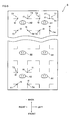
- Fig. 6 shows a plan view of the sheet member 8 on which printing has been performed
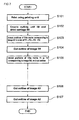
- Fig. 7 a flowchart of the cutting device 1.
- the drive carriage 85 is coupled to neither the cutting unit 50 nor the printing unit 60.
- the engagement portion of the cutting carriage 51 and the right hook 14 are engaged, and the cutting unit 50 is held at the right end of the guide rail 40a, while the engagement portion 61a of the printing carriage 61 and the left hook 12 are engaged, and the printing unit 60 is held at the left end of the guide rail 40a.
- the lower surfaces of the printer heads 62 are covered by the suction caps 71.
- step S101 shown in Fig. 7 on printing being started by an operator operating the operation portion 7, the drive carriage 85 is moved to the left based on an operation signal from the controller 9, and the drive carriage 85 and printing carriage 61 are coupled by the first coupling mechanism 86. Then, the engagement portion 61a and left hook 12 are disengaged along with the suction caps 71 being moved downward, and the printing unit 60 is in a condition wherein it is movable along the guide rail 40a.
- Fig. 6 An example of the sheet member 8 on which printing has been performed in this way is shown in Fig. 6 , wherein printing is performed on the sheet member 8 sequentially from a forward side.
- the L-shaped Trim marks T1 to T4 printed so as to surround each image are printed four to each image.
- the Trim mark T1 is printed on a left back side, the T2 on a right back side, the T3 on a right front side, and the T4 on a left front side respectively with respect to each image.
- step S102 on the heretofore described printing being completed, the printing unit 60 is moved to the left and held at the left end of the guide rail 40a, and the coupling of the drive carriage 85 and printing carriage 61 by the first coupling mechanism 86 is broken. Then, the drive carriage 85 is moved to the right and, after the drive carriage 85 and cutting carriage 51 are coupled by the second coupling mechanism 87, the engagement portion of the cutting carriage 51 and right hook 14 are disengaged, and the cutting unit 50 is in a condition wherein it is movable along the guide rail 40a.
- step S103 the positions of the Trim marks T1 to T4 corresponding to the image N1 are detected.
- the sheet member 8 is still in the same front-back position as at the completion of the printing, that is, the vicinity of the portions on which the images N1 and N2 are printed is mounted on the platen 30.
- the cutting unit 50 coupled to the drive carriage 85 it is automatically possible to position the Trim mark detection portion 54 above the Trim mark T1 printed corresponding to the image N1, and it is thus possible to sequentially detect the Trim mark positions, as will be described hereafter. Therefore, there being no need to newly set a position of starting a cutting process, it is possible to automatically set the cutting process starting position, meaning that it is possible to configure the control configuration simply.
- a left-right line h1 of the Trim mark T1 passes below the Trim mark detection portion 54.
- the inspection light is not reflected from the portions in which the Trim marks T1 to T4 are printed, as heretofore described, it is possible to detect a front-back position of the left-right line h1 from a result of received inspection light in the light receiving portion.
- a front-back line v1 of the Trim mark T1 passes below the Trim mark detection portion 54, and it is possible to detect a left-right position of the front-back line v1.
- first reference position t1 at which the left-right line h1 and front-back line v1 intersect.
- the cutting unit 50 is moved to the right, and positioned in the vicinity of the Trim mark T2.
- a second reference position t2 at which a left-right line and front-back line of the Trim mark T2 intersect is computed.
- the sheet member 8 is fed backward, and a third reference position t3 of the Trim mark T3 computed, and continuing, the cutting unit 50 is moved to the left, and a fourth reference position t4 of the Trim mark T4 computed.
- the printing position of the image N1 with respect to the first reference position t1 to fourth reference position t4 is computed in the controller 9. Then, cutting position data, indicating in what position on the sheet member 8 a cutting process is to be performed, are set.
- a configuration may also be such that the cutting position data are set in advance based on printing position data used when printing, and the cutting position data are corrected and set in accordance with the computed printing position of the image N1.
- step S104 based on the set cutting position data, a cutting process is performed along the outline of the image N1 by causing the cutter blade 53 to cut into the sheet member 8 while moving the cutting unit 50 from left and right and feeding the sheet member 8 frontward and backward.
- the cutting device 1 is of a configuration such as to carry out a cutting process from the image N1 printed on the back end after printing is completed, without carrying out a large back-feed of the sheet member 8 in a backward direction, as has been done to date. Therefore, by reducing the amount of feed of the sheet member 8 in the front-back direction, and the frequency with which the sheet member 8 is fed, misalignment of the sheet member 8 liable to occur when feeding is reduced, and it is possible to ensure positional accuracy of the sheet member 8 and cutter blade 53.
- step S105 the cutting unit 50 is moved to the right after the cutting process for the image N1 is completed and, in the same way as for the image N1, the first reference position t1 to fourth reference position t4 of the Trim marks T1 to T4 corresponding to the image N2 are computed.
- the cutting position data are set based on the computed first reference position t1 to fourth reference position t4, and a cutting process is performed along the outline of the image N2.
- the cutting unit 50 is moved to the left and the sheet member 8 fed backward, and the same kind of cutting process is performed for an image (not shown) adjacent in a forward direction to the image N1. In this way, cutting is carried out sequentially from an image printed on the back end. Then, in step S106, cutting is carried out for the image A1 printed on a front end portion, after which, proceeding to step S107, the flow finishes by a cutting being performed for the image A2 printed to the right of the image A1. According to the heretofore described flow, images are printed, and it is possible to obtain plural resulting articles cut into the outline forms of the images.
- Fig. 8 shows a plan view of the sheet member 8 on which are printed, aligned from left to right, images R1 and R2 of a form differing from that in Fig. 6 .
- the images R1 and R2 are of a form longer from front to back than the image A1 and the like.
- a description will be given of an operation of the cutting device 1 when carrying out a cutting process on the sheet member 8 on which the kinds of image R1 and R2 of Fig. 8 are printed using the printer heads 62.
- the first reference position t1 of the Trim mark T1 corresponding to the image R2 nearest to the completion positions is detected first.
- the second reference position t2, third reference position t3, and fourth reference position t4 are detected, in that order, and a cutting process is performed for the image R2.
- the fourth reference position t4 of the Trim mark T4 corresponding to the image R2 nearest to the completion position c is detected first.
- the third reference position t3, second reference position t2, and first reference position t1 are detected, in that order, and a cutting process is performed for the image R2.
- position detection is carried out sequentially from the Trim mark, of the plural Trim marks corresponding to the adjacent image, in the position nearest to the completion position (a position such that a small amount of front-back feed of the sheet member 8 is sufficient).
- a configuration may be such that three Trim marks are printed for one image, and also, the shape of the Trim marks is not limited to the L-shape.
Landscapes
- Life Sciences & Earth Sciences (AREA)
- Forests & Forestry (AREA)
- Engineering & Computer Science (AREA)
- Mechanical Engineering (AREA)
- Handling Of Sheets (AREA)
- Control Of Cutting Processes (AREA)
Claims (4)
- Dispositif de coupe (1), comprenant :un rail de guidage (40a) agencé de manière à s'étendre suivant une direction de balayage opposée à un moyen de retenue de support (30) de manière à retenir un support cible (8) ;une tête d'imprimante (62), agencée de manière à pouvoir se déplacer le long du rail de guidage (40a), afin d'imprimer une image (A1, A2, B1, B2, N1, N2) et des repères de référence (T1 à T4) sur la périphérie de l'image, en éjectant de l'encre vers le support cible maintenu par le moyen de retenue de support (30) ;une tête de coupe (53), agencée de manière à pouvoir être déplacée le long du rail de guidage (40a), afin de mettre en oeuvre une opération de coupe sur le support cible (8) maintenu par le moyen de retenue de support (30) ;un mécanisme d'alimentation de support (20) destiné à délivrer le support cible suivant une direction de transfert perpendiculaire à la direction de balayage ;une partie de détection de position de repère (54), agencée de manière à pouvoir être déplacée le long du rail de guidage (40a), afin de détecter des positions des repères de référence (T1 à T4) ; etune unité de commande (9) agencée de telle sorte que la tête d'imprimante (62) peut être commandée de manière à imprimer une pluralité d'images tout en délivrant le support cible dans la direction de transfert avec le mécanisme d'alimentation de support (20) et à imprimer des repères de référence (T1 à T4) sur la périphérie des images, les images de la pluralité d'images sont imprimées à partir d'un côté vers l'autre côté suivant la direction de transfert, dans lequel l'unité de commande présente une partie de définition de position de coupe (9) qui est mise en oeuvre, sur la base des positions des repères de référence obtenues par la partie de détection de position de repère (54), afin de détecter une position d'impression de l'image par rapport aux repères de référence (T1 à T4) et à régler une position d'opération de coupe correspondant à la position d'impression de l'image,dans lequel l'unité de commande (9) est, en outre, mise en oeuvre de telle sorte que la tête de coupe (50) exécute une opération de coupe dans une position d'opération de coupe définie par la partie de définition de position de coupe,le dispositif de coupe (1) étant caractérisé en ce que l'unité de commande (9) est, en outre, mise en oeuvre de telle sorte que les positions des repères de référence (T1 à T4) imprimés sur la périphérie d'une image de la pluralité d'images (A1, A2, B1, B2, N1, N2) imprimées au plus loin de l'autre côté dans la direction de transfert sont détectées avant le début d'une opération de coupe, et en ce qu'une opération de coupe est mise en oeuvre à partir de l'image (N1, N2) imprimée au plus loin de l'autre côté par rapport à une image (A1, A2) de la pluralité d'images (A1, A2, B1, B2, N1, N2) imprimées au plus loin du premier côté dans la direction de transfert le long desdits repères de référence (T1 à T4) détectés de chaque image (A1, A2, B1, B2, N1, N2).
- Dispositif de coupe (1) selon la revendication 1, caractérisé en ce qu'au moins trois des repères de référence sont imprimés sur la périphérie de l'image par la tête d'imprimante (62), et
les positions d'au moins trois repères de référence imprimés sur la périphérie de l'image (N1, N2) imprimée au plus loin de l'autre côté sont détectées par la partie de détection de position de repère (54) avant le début d'une opération de coupe. - Dispositif de coupe (1) selon la revendication 1 ou 2, caractérisé en ce que, avant le début d'une opération de coupe de l'image, la position d'impression de l'image est détectée en détectant la position d'un premier repère de référence, parmi les repères de référence imprimés sur la périphérie de l'image, positionné au plus près de la partie de détection de position de repère avec la partie de détection de position de repère, en déplaçant la partie de détection de position de repère dans la direction de balayage et en détectant la position d'un deuxième repère de référence imprimé et positionné dans la direction de balayage par rapport au premier repère de référence, et en délivrant le support cible dans la direction de transfert avec le mécanisme d'alimentation de support et en détectant la position d'un troisième repère de référence imprimé et positionné dans la direction de transfert par rapport au deuxième repère de référence.
- Procédé de coupe d'un dispositif de coupe (1) qui imprime une pluralité d'images (A1, A2, B1, B2, N1, N2) et de repères de référence (T1 à T4) sur une périphérie de chaque image à partir de l'autre côté vers le premier côté, tout en délivrant un support cible (8) à partir du premier côté vers l'autre côté dans une direction de transfert, détecte une position d'impression de l'image par rapport aux repères de référence sur la base des positions des repères de référence (T1 à T4), définit une position dans laquelle il est possible d'exécuter une opération de coupe avec une tête de coupe (53), et exécute une opération de coupe, le procédé de coupe étant caractérisé par le fait qu'il comporte :une première étape de détection des positions des repères de référence imprimés sur la périphérie d'une image (N1, N2) d'une pluralité d'images (A1, A2, B1, B2, N1, N2) imprimées au plus loin de l'autre côté dans la direction de transfert le long desdits repères de référence détectés (T1 à T4) avant de démarrer une opération de coupe ; etune seconde étape d'exécution d'une opération de coupe à partir de l'image imprimée au plus loin de l'autre côté vers l'image imprimée au plus loin du premier côté dans la direction de transfert.
Applications Claiming Priority (2)
| Application Number | Priority Date | Filing Date | Title |
|---|---|---|---|
| JP2009201303A JP5336980B2 (ja) | 2009-09-01 | 2009-09-01 | カッティング装置およびそのカット方法 |
| PCT/JP2010/003479 WO2011027493A1 (fr) | 2009-09-01 | 2010-05-25 | Dispositif de coupe et procédé de coupe de celui-ci |
Publications (3)
| Publication Number | Publication Date |
|---|---|
| EP2474422A1 EP2474422A1 (fr) | 2012-07-11 |
| EP2474422A4 EP2474422A4 (fr) | 2014-02-12 |
| EP2474422B1 true EP2474422B1 (fr) | 2015-02-11 |
Family
ID=43649053
Family Applications (1)
| Application Number | Title | Priority Date | Filing Date |
|---|---|---|---|
| EP10813448.7A Not-in-force EP2474422B1 (fr) | 2009-09-01 | 2010-05-25 | Dispositif de coupe et procédé de coupe de celui-ci |
Country Status (6)
| Country | Link |
|---|---|
| US (1) | US8870363B2 (fr) |
| EP (1) | EP2474422B1 (fr) |
| JP (1) | JP5336980B2 (fr) |
| KR (1) | KR101344431B1 (fr) |
| CN (1) | CN102481793B (fr) |
| WO (1) | WO2011027493A1 (fr) |
Families Citing this family (35)
| Publication number | Priority date | Publication date | Assignee | Title |
|---|---|---|---|---|
| JP5973734B2 (ja) * | 2012-01-25 | 2016-08-23 | 株式会社ミマキエンジニアリング | 表示制御プログラム、記録媒体、表示制御装置及び媒体加工装置 |
| JP5912612B2 (ja) * | 2012-02-07 | 2016-04-27 | 株式会社ミマキエンジニアリング | カッティング装置、カッティング方法及びプログラム |
| CN102873768B (zh) * | 2012-10-25 | 2015-08-19 | 河南天丰节能板材科技股份有限公司 | 复合板自动切割方法及其专用的切割装置 |
| WO2014209340A1 (fr) | 2013-06-28 | 2014-12-31 | Hewlett-Packard Development Company, L.P. | Impression de trames imprimées en s'appuyant sur les longueurs de trame mesurées |
| JP6144140B2 (ja) * | 2013-07-22 | 2017-06-07 | ローランドディー.ジー.株式会社 | カッティング機能を備えたプリンタおよび印刷方法 |
| CN104552375B (zh) * | 2013-10-12 | 2016-09-14 | 北新集团建材股份有限公司 | 一种封边带切断装置 |
| JP6148976B2 (ja) * | 2013-12-18 | 2017-06-14 | 株式会社ミマキエンジニアリング | 境界決定方法およびメディア切断方法 |
| CN104294574B (zh) * | 2014-08-14 | 2017-06-23 | 拓卡奔马机电科技有限公司 | 裁床的裁剪区域自动确定方法 |
| JP6406508B2 (ja) * | 2014-10-14 | 2018-10-17 | セイコーエプソン株式会社 | 液体吐出装置及び液体吐出方法 |
| CN105620055A (zh) * | 2014-11-27 | 2016-06-01 | 罗兰Dg有限公司 | 打印及切割装置 |
| CN105620056A (zh) * | 2014-11-27 | 2016-06-01 | 罗兰Dg有限公司 | 打印及切割装置 |
| CN105691010A (zh) * | 2014-11-27 | 2016-06-22 | 罗兰Dg有限公司 | 打印及切割装置 |
| CN104589809A (zh) * | 2015-02-08 | 2015-05-06 | 李丽容 | 一种用于票据打印机的自动切纸部件 |
| JP6471595B2 (ja) * | 2015-04-13 | 2019-02-20 | 株式会社リコー | 画像形成装置 |
| GB2542259B (en) * | 2015-07-20 | 2019-02-13 | Shenzhen Dekia Science And Tech Co Ltd | Method and system of self-adaptive adjustment for post-printing treatment |
| CN104999809B (zh) * | 2015-07-20 | 2018-01-23 | 深圳市索登科技有限公司 | 一种印后处理自适应调整方法及系统 |
| DE102016102217A1 (de) * | 2016-02-09 | 2017-08-10 | Fraunhofer-Gesellschaft zur Förderung der angewandten Forschung e.V. | Kartusche für eine Druckeinrichtung, Druckeinrichtung sowie Verfahren zum Einbringen einer Perforation oder von Schnitten und Verwendung einer Kartusche |
| US10099489B2 (en) * | 2016-04-15 | 2018-10-16 | Gp Squared Technologies, Inc. | Apparatus and method for trimming a print sheet, and registering the location of an image |
| JP6093078B1 (ja) * | 2016-07-21 | 2017-03-08 | ローランドディー.ジー.株式会社 | カッティング装置 |
| JP6153682B1 (ja) * | 2017-02-09 | 2017-06-28 | ローランドディー.ジー.株式会社 | カッティング装置 |
| CN110494293B (zh) * | 2017-06-20 | 2021-06-11 | 惠普发展公司,有限责任合伙企业 | 切割打印基材 |
| US11520544B2 (en) | 2017-07-14 | 2022-12-06 | Georgia-Pacific Corrugated Llc | Waste determination for generating control plans for digital pre-print paper, sheet, and box manufacturing systems |
| US20190016551A1 (en) | 2017-07-14 | 2019-01-17 | Georgia-Pacific Corrugated, LLC | Reel editor for pre-print paper, sheet, and box manufacturing systems |
| US11485101B2 (en) | 2017-07-14 | 2022-11-01 | Georgia-Pacific Corrugated Llc | Controls for paper, sheet, and box manufacturing systems |
| US10642551B2 (en) | 2017-07-14 | 2020-05-05 | Georgia-Pacific Corrugated Llc | Engine for generating control plans for digital pre-print paper, sheet, and box manufacturing systems |
| US11449290B2 (en) | 2017-07-14 | 2022-09-20 | Georgia-Pacific Corrugated Llc | Control plan for paper, sheet, and box manufacturing systems |
| CN109304744B (zh) * | 2017-07-28 | 2020-10-16 | 天津阳光彩印股份有限公司 | 一种可自动控制裁切的纸品印刷机 |
| JP7031497B2 (ja) * | 2018-05-30 | 2022-03-08 | 株式会社リコー | 位置出し用部材、画像付与装置、印刷対象をセットする方法、プログラム |
| US11107147B2 (en) | 2018-11-16 | 2021-08-31 | The North Face Apparel Corp. | Systems and methods for end-to-end article management |
| JP7043388B2 (ja) * | 2018-11-30 | 2022-03-29 | ローランドディー.ジー.株式会社 | カッティングヘッド付きプリンタ |
| JP7130586B2 (ja) * | 2019-03-26 | 2022-09-05 | ローランドディー.ジー.株式会社 | カッティング装置 |
| JP7528567B2 (ja) | 2020-06-30 | 2024-08-06 | 株式会社リコー | シート加工装置及び画像形成システム |
| JP2025024741A (ja) * | 2023-08-08 | 2025-02-21 | 京セラドキュメントソリューションズ株式会社 | 画像形成制御方法、画像形成装置 |
| JP2025084637A (ja) * | 2023-11-22 | 2025-06-03 | 株式会社ミマキエンジニアリング | 加工装置、およびパターンの形成方法 |
| CN120697458B (zh) * | 2025-08-26 | 2025-12-16 | 梅木精密工业(珠海)有限公司 | 打印裁切一体机及图片制作方法 |
Family Cites Families (19)
| Publication number | Priority date | Publication date | Assignee | Title |
|---|---|---|---|---|
| JPH0636798U (ja) * | 1992-10-21 | 1994-05-17 | ジューキ株式会社 | カッタ装置 |
| JP3333312B2 (ja) * | 1994-03-24 | 2002-10-15 | ローランドディー.ジー.株式会社 | 画像作成および切り抜き装置 |
| JPH07314844A (ja) * | 1994-05-25 | 1995-12-05 | Ricoh Co Ltd | プリンタ装置 |
| JP3589441B2 (ja) * | 1997-10-06 | 2004-11-17 | 株式会社ミマキエンジニアリング | カッティングプロッタと該プロッタを用いたシール材のカット方法 |
| JP2001268310A (ja) * | 2000-03-17 | 2001-09-28 | Canon Inc | 画像形成装置及びロール状記録媒体切断方法 |
| JP3640588B2 (ja) * | 2000-03-22 | 2005-04-20 | ローランドディー.ジー.株式会社 | 切断装置および円形状マークの中心位置の検出方法 |
| US7055418B2 (en) * | 2000-04-06 | 2006-06-06 | Fotoba International S.R.L. | Device for trimming and automatic cutting of images on paper and other graphic and photographic substrates, in particular of large size |
| JP2002160410A (ja) * | 2000-11-27 | 2002-06-04 | Noritsu Koki Co Ltd | インクジェット式プリンタ |
| US6672187B2 (en) | 2001-04-05 | 2004-01-06 | Mikkelsen Graphic Engineering, Inc. | Method and apparatus for rapid precision cutting of graphics areas from sheets |
| JP2003025660A (ja) * | 2001-07-12 | 2003-01-29 | Sharp Corp | 用紙カット機能付きインクジェットプリンタ |
| US6932528B2 (en) * | 2003-12-08 | 2005-08-23 | Hewlett-Packard Development Company, L.P. | Cutter position control in a web fed imaging system |
| JP2005297248A (ja) | 2004-04-07 | 2005-10-27 | Roland Dg Corp | 画像作成および切り抜き装置 |
| JP4428132B2 (ja) * | 2004-05-11 | 2010-03-10 | セイコーエプソン株式会社 | 連続用紙のマーク検出方法、マーク検出検出機構およびプリンタ |
| US7422386B2 (en) * | 2004-07-07 | 2008-09-09 | Roland Dg Corporation | Image creation and cutting apparatus |
| JP4530761B2 (ja) * | 2004-08-18 | 2010-08-25 | ローランドディー.ジー.株式会社 | カッティングヘッド付きインクジェットプリンタ |
| US7249903B2 (en) * | 2004-11-29 | 2007-07-31 | Astro-Med, Inc. | Assembly for feeding a continuous roll of web material to a sheet fed printing device |
| JP2007001180A (ja) * | 2005-06-24 | 2007-01-11 | Canon Finetech Inc | 印字装置及び印字方法 |
| JP4990002B2 (ja) * | 2007-03-30 | 2012-08-01 | 株式会社ミマキエンジニアリング | プリンタ・プロッタ装置 |
| JP4990001B2 (ja) * | 2007-03-30 | 2012-08-01 | 株式会社ミマキエンジニアリング | プリンタ・プロッタ装置 |
-
2009
- 2009-09-01 JP JP2009201303A patent/JP5336980B2/ja active Active
-
2010
- 2010-05-25 WO PCT/JP2010/003479 patent/WO2011027493A1/fr not_active Ceased
- 2010-05-25 CN CN201080037823.1A patent/CN102481793B/zh active Active
- 2010-05-25 EP EP10813448.7A patent/EP2474422B1/fr not_active Not-in-force
- 2010-05-25 KR KR1020127004892A patent/KR101344431B1/ko not_active Expired - Fee Related
- 2010-05-25 US US13/391,819 patent/US8870363B2/en active Active
Also Published As
| Publication number | Publication date |
|---|---|
| CN102481793A (zh) | 2012-05-30 |
| KR20120046286A (ko) | 2012-05-09 |
| KR101344431B1 (ko) | 2013-12-26 |
| EP2474422A4 (fr) | 2014-02-12 |
| JP2011051192A (ja) | 2011-03-17 |
| CN102481793B (zh) | 2014-12-31 |
| EP2474422A1 (fr) | 2012-07-11 |
| US20120148326A1 (en) | 2012-06-14 |
| US8870363B2 (en) | 2014-10-28 |
| JP5336980B2 (ja) | 2013-11-06 |
| WO2011027493A1 (fr) | 2011-03-10 |
Similar Documents
| Publication | Publication Date | Title |
|---|---|---|
| EP2474422B1 (fr) | Dispositif de coupe et procédé de coupe de celui-ci | |
| KR101360253B1 (ko) | 프린터 커터 | |
| US11338595B2 (en) | Print apparatus, method for controlling the same, and storage medium | |
| JP5625989B2 (ja) | 画像形成装置 | |
| JP5678290B2 (ja) | インクジェット記録装置 | |
| US8657402B2 (en) | Image forming apparatus including sheet cutting device | |
| JP5928093B2 (ja) | インクジェット記録装置 | |
| JP2020044624A (ja) | カッティング装置、及び、裁断方法 | |
| TWI513598B (zh) | 印表機及印表機的控制方法 | |
| US10166793B2 (en) | Serial-type recording apparatus | |
| JP2014104635A (ja) | 画像形成装置 | |
| JP2017209798A (ja) | 液体吐出装置及び液体吐出方法 | |
| JP2012218339A (ja) | プリンター | |
| JP2007268826A (ja) | 印字装置及び印字方法 | |
| JP6031794B2 (ja) | インクジェット記録装置 | |
| JP5982849B2 (ja) | 画像記録装置 | |
| JP2018202758A (ja) | 液体吐出装置及び媒体変形抑制方法 | |
| JP2003276172A (ja) | インクジェット記録装置のヘッド駆動補正方法 | |
| JP2025088871A (ja) | 媒体処理装置 | |
| JP2025088871A5 (fr) | ||
| JP4360185B2 (ja) | シリアルプリンタ | |
| JP2010023292A (ja) | プリンタ装置 | |
| JP2005305820A (ja) | インクジェット記録装置 | |
| JP2008018604A (ja) | インクジェット記録装置 | |
| JP2009214553A (ja) | シリアルプリンタ、シリアルプリンタにおける印刷制御方法 |
Legal Events
| Date | Code | Title | Description |
|---|---|---|---|
| PUAI | Public reference made under article 153(3) epc to a published international application that has entered the european phase |
Free format text: ORIGINAL CODE: 0009012 |
|
| 17P | Request for examination filed |
Effective date: 20120222 |
|
| AK | Designated contracting states |
Kind code of ref document: A1 Designated state(s): AL AT BE BG CH CY CZ DE DK EE ES FI FR GB GR HR HU IE IS IT LI LT LU LV MC MK MT NL NO PL PT RO SE SI SK SM TR |
|
| DAX | Request for extension of the european patent (deleted) | ||
| REG | Reference to a national code |
Ref country code: DE Ref legal event code: R079 Ref document number: 602010022255 Country of ref document: DE Free format text: PREVIOUS MAIN CLASS: B41J0011680000 Ipc: B41J0011660000 |
|
| A4 | Supplementary search report drawn up and despatched |
Effective date: 20140113 |
|
| RIC1 | Information provided on ipc code assigned before grant |
Ipc: B41J 11/70 20060101ALI20140107BHEP Ipc: B26D 5/34 20060101ALI20140107BHEP Ipc: B26F 1/38 20060101ALI20140107BHEP Ipc: B26D 5/32 20060101ALI20140107BHEP Ipc: B41J 11/66 20060101AFI20140107BHEP Ipc: B26D 1/04 20060101ALI20140107BHEP Ipc: B26D 5/30 20060101ALI20140107BHEP |
|
| GRAP | Despatch of communication of intention to grant a patent |
Free format text: ORIGINAL CODE: EPIDOSNIGR1 |
|
| INTG | Intention to grant announced |
Effective date: 20140903 |
|
| GRAS | Grant fee paid |
Free format text: ORIGINAL CODE: EPIDOSNIGR3 |
|
| GRAA | (expected) grant |
Free format text: ORIGINAL CODE: 0009210 |
|
| AK | Designated contracting states |
Kind code of ref document: B1 Designated state(s): AL AT BE BG CH CY CZ DE DK EE ES FI FR GB GR HR HU IE IS IT LI LT LU LV MC MK MT NL NO PL PT RO SE SI SK SM TR |
|
| REG | Reference to a national code |
Ref country code: GB Ref legal event code: FG4D |
|
| REG | Reference to a national code |
Ref country code: CH Ref legal event code: EP |
|
| REG | Reference to a national code |
Ref country code: IE Ref legal event code: FG4D |
|
| REG | Reference to a national code |
Ref country code: AT Ref legal event code: REF Ref document number: 709785 Country of ref document: AT Kind code of ref document: T Effective date: 20150315 |
|
| REG | Reference to a national code |
Ref country code: DE Ref legal event code: R096 Ref document number: 602010022255 Country of ref document: DE Effective date: 20150326 |
|
| REG | Reference to a national code |
Ref country code: NL Ref legal event code: VDEP Effective date: 20150211 |
|
| REG | Reference to a national code |
Ref country code: AT Ref legal event code: MK05 Ref document number: 709785 Country of ref document: AT Kind code of ref document: T Effective date: 20150211 |
|
| REG | Reference to a national code |
Ref country code: LT Ref legal event code: MG4D |
|
| PG25 | Lapsed in a contracting state [announced via postgrant information from national office to epo] |
Ref country code: FI Free format text: LAPSE BECAUSE OF FAILURE TO SUBMIT A TRANSLATION OF THE DESCRIPTION OR TO PAY THE FEE WITHIN THE PRESCRIBED TIME-LIMIT Effective date: 20150211 Ref country code: SE Free format text: LAPSE BECAUSE OF FAILURE TO SUBMIT A TRANSLATION OF THE DESCRIPTION OR TO PAY THE FEE WITHIN THE PRESCRIBED TIME-LIMIT Effective date: 20150211 Ref country code: HR Free format text: LAPSE BECAUSE OF FAILURE TO SUBMIT A TRANSLATION OF THE DESCRIPTION OR TO PAY THE FEE WITHIN THE PRESCRIBED TIME-LIMIT Effective date: 20150211 Ref country code: LT Free format text: LAPSE BECAUSE OF FAILURE TO SUBMIT A TRANSLATION OF THE DESCRIPTION OR TO PAY THE FEE WITHIN THE PRESCRIBED TIME-LIMIT Effective date: 20150211 Ref country code: ES Free format text: LAPSE BECAUSE OF FAILURE TO SUBMIT A TRANSLATION OF THE DESCRIPTION OR TO PAY THE FEE WITHIN THE PRESCRIBED TIME-LIMIT Effective date: 20150211 Ref country code: NO Free format text: LAPSE BECAUSE OF FAILURE TO SUBMIT A TRANSLATION OF THE DESCRIPTION OR TO PAY THE FEE WITHIN THE PRESCRIBED TIME-LIMIT Effective date: 20150511 |
|
| PG25 | Lapsed in a contracting state [announced via postgrant information from national office to epo] |
Ref country code: AT Free format text: LAPSE BECAUSE OF FAILURE TO SUBMIT A TRANSLATION OF THE DESCRIPTION OR TO PAY THE FEE WITHIN THE PRESCRIBED TIME-LIMIT Effective date: 20150211 Ref country code: IS Free format text: LAPSE BECAUSE OF FAILURE TO SUBMIT A TRANSLATION OF THE DESCRIPTION OR TO PAY THE FEE WITHIN THE PRESCRIBED TIME-LIMIT Effective date: 20150611 Ref country code: LV Free format text: LAPSE BECAUSE OF FAILURE TO SUBMIT A TRANSLATION OF THE DESCRIPTION OR TO PAY THE FEE WITHIN THE PRESCRIBED TIME-LIMIT Effective date: 20150211 Ref country code: NL Free format text: LAPSE BECAUSE OF FAILURE TO SUBMIT A TRANSLATION OF THE DESCRIPTION OR TO PAY THE FEE WITHIN THE PRESCRIBED TIME-LIMIT Effective date: 20150211 Ref country code: GR Free format text: LAPSE BECAUSE OF FAILURE TO SUBMIT A TRANSLATION OF THE DESCRIPTION OR TO PAY THE FEE WITHIN THE PRESCRIBED TIME-LIMIT Effective date: 20150512 |
|
| PG25 | Lapsed in a contracting state [announced via postgrant information from national office to epo] |
Ref country code: RO Free format text: LAPSE BECAUSE OF FAILURE TO SUBMIT A TRANSLATION OF THE DESCRIPTION OR TO PAY THE FEE WITHIN THE PRESCRIBED TIME-LIMIT Effective date: 20150211 Ref country code: DK Free format text: LAPSE BECAUSE OF FAILURE TO SUBMIT A TRANSLATION OF THE DESCRIPTION OR TO PAY THE FEE WITHIN THE PRESCRIBED TIME-LIMIT Effective date: 20150211 Ref country code: CZ Free format text: LAPSE BECAUSE OF FAILURE TO SUBMIT A TRANSLATION OF THE DESCRIPTION OR TO PAY THE FEE WITHIN THE PRESCRIBED TIME-LIMIT Effective date: 20150211 Ref country code: EE Free format text: LAPSE BECAUSE OF FAILURE TO SUBMIT A TRANSLATION OF THE DESCRIPTION OR TO PAY THE FEE WITHIN THE PRESCRIBED TIME-LIMIT Effective date: 20150211 Ref country code: SK Free format text: LAPSE BECAUSE OF FAILURE TO SUBMIT A TRANSLATION OF THE DESCRIPTION OR TO PAY THE FEE WITHIN THE PRESCRIBED TIME-LIMIT Effective date: 20150211 |
|
| REG | Reference to a national code |
Ref country code: DE Ref legal event code: R097 Ref document number: 602010022255 Country of ref document: DE |
|
| PG25 | Lapsed in a contracting state [announced via postgrant information from national office to epo] |
Ref country code: PL Free format text: LAPSE BECAUSE OF FAILURE TO SUBMIT A TRANSLATION OF THE DESCRIPTION OR TO PAY THE FEE WITHIN THE PRESCRIBED TIME-LIMIT Effective date: 20150211 |
|
| PLBE | No opposition filed within time limit |
Free format text: ORIGINAL CODE: 0009261 |
|
| STAA | Information on the status of an ep patent application or granted ep patent |
Free format text: STATUS: NO OPPOSITION FILED WITHIN TIME LIMIT |
|
| PG25 | Lapsed in a contracting state [announced via postgrant information from national office to epo] |
Ref country code: IT Free format text: LAPSE BECAUSE OF FAILURE TO SUBMIT A TRANSLATION OF THE DESCRIPTION OR TO PAY THE FEE WITHIN THE PRESCRIBED TIME-LIMIT Effective date: 20150211 |
|
| REG | Reference to a national code |
Ref country code: CH Ref legal event code: PL |
|
| 26N | No opposition filed |
Effective date: 20151112 |
|
| PG25 | Lapsed in a contracting state [announced via postgrant information from national office to epo] |
Ref country code: LU Free format text: LAPSE BECAUSE OF FAILURE TO SUBMIT A TRANSLATION OF THE DESCRIPTION OR TO PAY THE FEE WITHIN THE PRESCRIBED TIME-LIMIT Effective date: 20150525 Ref country code: CH Free format text: LAPSE BECAUSE OF NON-PAYMENT OF DUE FEES Effective date: 20150531 Ref country code: MC Free format text: LAPSE BECAUSE OF FAILURE TO SUBMIT A TRANSLATION OF THE DESCRIPTION OR TO PAY THE FEE WITHIN THE PRESCRIBED TIME-LIMIT Effective date: 20150211 Ref country code: LI Free format text: LAPSE BECAUSE OF NON-PAYMENT OF DUE FEES Effective date: 20150531 |
|
| REG | Reference to a national code |
Ref country code: IE Ref legal event code: MM4A |
|
| PG25 | Lapsed in a contracting state [announced via postgrant information from national office to epo] |
Ref country code: SI Free format text: LAPSE BECAUSE OF FAILURE TO SUBMIT A TRANSLATION OF THE DESCRIPTION OR TO PAY THE FEE WITHIN THE PRESCRIBED TIME-LIMIT Effective date: 20150211 |
|
| REG | Reference to a national code |
Ref country code: FR Ref legal event code: PLFP Year of fee payment: 7 |
|
| PG25 | Lapsed in a contracting state [announced via postgrant information from national office to epo] |
Ref country code: IE Free format text: LAPSE BECAUSE OF NON-PAYMENT OF DUE FEES Effective date: 20150525 |
|
| PG25 | Lapsed in a contracting state [announced via postgrant information from national office to epo] |
Ref country code: BE Free format text: LAPSE BECAUSE OF FAILURE TO SUBMIT A TRANSLATION OF THE DESCRIPTION OR TO PAY THE FEE WITHIN THE PRESCRIBED TIME-LIMIT Effective date: 20150211 |
|
| PGFP | Annual fee paid to national office [announced via postgrant information from national office to epo] |
Ref country code: GB Payment date: 20160525 Year of fee payment: 7 |
|
| PGFP | Annual fee paid to national office [announced via postgrant information from national office to epo] |
Ref country code: FR Payment date: 20160412 Year of fee payment: 7 |
|
| PG25 | Lapsed in a contracting state [announced via postgrant information from national office to epo] |
Ref country code: MT Free format text: LAPSE BECAUSE OF FAILURE TO SUBMIT A TRANSLATION OF THE DESCRIPTION OR TO PAY THE FEE WITHIN THE PRESCRIBED TIME-LIMIT Effective date: 20150211 |
|
| PG25 | Lapsed in a contracting state [announced via postgrant information from national office to epo] |
Ref country code: BG Free format text: LAPSE BECAUSE OF FAILURE TO SUBMIT A TRANSLATION OF THE DESCRIPTION OR TO PAY THE FEE WITHIN THE PRESCRIBED TIME-LIMIT Effective date: 20150211 Ref country code: SM Free format text: LAPSE BECAUSE OF FAILURE TO SUBMIT A TRANSLATION OF THE DESCRIPTION OR TO PAY THE FEE WITHIN THE PRESCRIBED TIME-LIMIT Effective date: 20150211 Ref country code: HU Free format text: LAPSE BECAUSE OF FAILURE TO SUBMIT A TRANSLATION OF THE DESCRIPTION OR TO PAY THE FEE WITHIN THE PRESCRIBED TIME-LIMIT; INVALID AB INITIO Effective date: 20100525 |
|
| PG25 | Lapsed in a contracting state [announced via postgrant information from national office to epo] |
Ref country code: CY Free format text: LAPSE BECAUSE OF FAILURE TO SUBMIT A TRANSLATION OF THE DESCRIPTION OR TO PAY THE FEE WITHIN THE PRESCRIBED TIME-LIMIT Effective date: 20150211 |
|
| PG25 | Lapsed in a contracting state [announced via postgrant information from national office to epo] |
Ref country code: TR Free format text: LAPSE BECAUSE OF FAILURE TO SUBMIT A TRANSLATION OF THE DESCRIPTION OR TO PAY THE FEE WITHIN THE PRESCRIBED TIME-LIMIT Effective date: 20150211 |
|
| GBPC | Gb: european patent ceased through non-payment of renewal fee |
Effective date: 20170525 |
|
| REG | Reference to a national code |
Ref country code: FR Ref legal event code: ST Effective date: 20180131 |
|
| PG25 | Lapsed in a contracting state [announced via postgrant information from national office to epo] |
Ref country code: GB Free format text: LAPSE BECAUSE OF NON-PAYMENT OF DUE FEES Effective date: 20170525 |
|
| PG25 | Lapsed in a contracting state [announced via postgrant information from national office to epo] |
Ref country code: FR Free format text: LAPSE BECAUSE OF NON-PAYMENT OF DUE FEES Effective date: 20170531 |
|
| PG25 | Lapsed in a contracting state [announced via postgrant information from national office to epo] |
Ref country code: PT Free format text: LAPSE BECAUSE OF FAILURE TO SUBMIT A TRANSLATION OF THE DESCRIPTION OR TO PAY THE FEE WITHIN THE PRESCRIBED TIME-LIMIT Effective date: 20150211 Ref country code: MK Free format text: LAPSE BECAUSE OF FAILURE TO SUBMIT A TRANSLATION OF THE DESCRIPTION OR TO PAY THE FEE WITHIN THE PRESCRIBED TIME-LIMIT Effective date: 20150211 |
|
| PG25 | Lapsed in a contracting state [announced via postgrant information from national office to epo] |
Ref country code: AL Free format text: LAPSE BECAUSE OF FAILURE TO SUBMIT A TRANSLATION OF THE DESCRIPTION OR TO PAY THE FEE WITHIN THE PRESCRIBED TIME-LIMIT Effective date: 20150211 |
|
| PGFP | Annual fee paid to national office [announced via postgrant information from national office to epo] |
Ref country code: DE Payment date: 20240328 Year of fee payment: 15 |
|
| REG | Reference to a national code |
Ref country code: DE Ref legal event code: R119 Ref document number: 602010022255 Country of ref document: DE |
|
| PG25 | Lapsed in a contracting state [announced via postgrant information from national office to epo] |
Ref country code: DE Free format text: LAPSE BECAUSE OF NON-PAYMENT OF DUE FEES Effective date: 20251202 |