EP2474729B1 - Conducteur de commande de véhicule avec un retardateur et une machine d'expansion - Google Patents
Conducteur de commande de véhicule avec un retardateur et une machine d'expansion Download PDFInfo
- Publication number
- EP2474729B1 EP2474729B1 EP12002460.9A EP12002460A EP2474729B1 EP 2474729 B1 EP2474729 B1 EP 2474729B1 EP 12002460 A EP12002460 A EP 12002460A EP 2474729 B1 EP2474729 B1 EP 2474729B1
- Authority
- EP
- European Patent Office
- Prior art keywords
- retarder
- rotor
- working medium
- expansion machine
- transmission
- Prior art date
- Legal status (The legal status is an assumption and is not a legal conclusion. Google has not performed a legal analysis and makes no representation as to the accuracy of the status listed.)
- Not-in-force
Links
- 230000005540 biological transmission Effects 0.000 claims description 43
- 239000012530 fluid Substances 0.000 claims description 8
- ZZUFCTLCJUWOSV-UHFFFAOYSA-N furosemide Chemical compound C1=C(Cl)C(S(=O)(=O)N)=CC(C(O)=O)=C1NCC1=CC=CO1 ZZUFCTLCJUWOSV-UHFFFAOYSA-N 0.000 claims 1
- 230000008878 coupling Effects 0.000 description 7
- 238000010168 coupling process Methods 0.000 description 7
- 238000005859 coupling reaction Methods 0.000 description 7
- 239000002826 coolant Substances 0.000 description 6
- 238000001816 cooling Methods 0.000 description 5
- 230000013011 mating Effects 0.000 description 5
- 230000002349 favourable effect Effects 0.000 description 3
- 230000001105 regulatory effect Effects 0.000 description 2
- XLYOFNOQVPJJNP-UHFFFAOYSA-N water Substances O XLYOFNOQVPJJNP-UHFFFAOYSA-N 0.000 description 2
- AWFYPPSBLUWMFQ-UHFFFAOYSA-N 2-[5-[2-(2,3-dihydro-1H-inden-2-ylamino)pyrimidin-5-yl]-1,3,4-oxadiazol-2-yl]-1-(1,4,6,7-tetrahydropyrazolo[4,3-c]pyridin-5-yl)ethanone Chemical compound C1C(CC2=CC=CC=C12)NC1=NC=C(C=N1)C1=NN=C(O1)CC(=O)N1CC2=C(CC1)NN=C2 AWFYPPSBLUWMFQ-UHFFFAOYSA-N 0.000 description 1
- 230000009471 action Effects 0.000 description 1
- 230000008901 benefit Effects 0.000 description 1
- 238000002485 combustion reaction Methods 0.000 description 1
- 238000013016 damping Methods 0.000 description 1
- 230000001419 dependent effect Effects 0.000 description 1
- 230000000694 effects Effects 0.000 description 1
- 230000005520 electrodynamics Effects 0.000 description 1
- 238000005516 engineering process Methods 0.000 description 1
- 230000006870 function Effects 0.000 description 1
- 230000017525 heat dissipation Effects 0.000 description 1
- 230000010354 integration Effects 0.000 description 1
- 238000004519 manufacturing process Methods 0.000 description 1
- 239000000203 mixture Substances 0.000 description 1
- 230000004048 modification Effects 0.000 description 1
- 238000012986 modification Methods 0.000 description 1
- 230000009467 reduction Effects 0.000 description 1
- 238000010008 shearing Methods 0.000 description 1
Images
Classifications
-
- F—MECHANICAL ENGINEERING; LIGHTING; HEATING; WEAPONS; BLASTING
- F02—COMBUSTION ENGINES; HOT-GAS OR COMBUSTION-PRODUCT ENGINE PLANTS
- F02G—HOT GAS OR COMBUSTION-PRODUCT POSITIVE-DISPLACEMENT ENGINE PLANTS; USE OF WASTE HEAT OF COMBUSTION ENGINES; NOT OTHERWISE PROVIDED FOR
- F02G5/00—Profiting from waste heat of combustion engines, not otherwise provided for
-
- F—MECHANICAL ENGINEERING; LIGHTING; HEATING; WEAPONS; BLASTING
- F01—MACHINES OR ENGINES IN GENERAL; ENGINE PLANTS IN GENERAL; STEAM ENGINES
- F01K—STEAM ENGINE PLANTS; STEAM ACCUMULATORS; ENGINE PLANTS NOT OTHERWISE PROVIDED FOR; ENGINES USING SPECIAL WORKING FLUIDS OR CYCLES
- F01K23/00—Plants characterised by more than one engine delivering power external to the plant, the engines being driven by different fluids
- F01K23/02—Plants characterised by more than one engine delivering power external to the plant, the engines being driven by different fluids the engine cycles being thermally coupled
- F01K23/06—Plants characterised by more than one engine delivering power external to the plant, the engines being driven by different fluids the engine cycles being thermally coupled combustion heat from one cycle heating the fluid in another cycle
- F01K23/065—Plants characterised by more than one engine delivering power external to the plant, the engines being driven by different fluids the engine cycles being thermally coupled combustion heat from one cycle heating the fluid in another cycle the combustion taking place in an internal combustion piston engine, e.g. a diesel engine
-
- Y—GENERAL TAGGING OF NEW TECHNOLOGICAL DEVELOPMENTS; GENERAL TAGGING OF CROSS-SECTIONAL TECHNOLOGIES SPANNING OVER SEVERAL SECTIONS OF THE IPC; TECHNICAL SUBJECTS COVERED BY FORMER USPC CROSS-REFERENCE ART COLLECTIONS [XRACs] AND DIGESTS
- Y02—TECHNOLOGIES OR APPLICATIONS FOR MITIGATION OR ADAPTATION AGAINST CLIMATE CHANGE
- Y02T—CLIMATE CHANGE MITIGATION TECHNOLOGIES RELATED TO TRANSPORTATION
- Y02T10/00—Road transport of goods or passengers
- Y02T10/10—Internal combustion engine [ICE] based vehicles
- Y02T10/12—Improving ICE efficiencies
Definitions
- the invention relates to a vehicle drive train, in particular a truck, passenger car, rail vehicle or other motor vehicle, which is a hydrodynamic retarder for hydrodynamic braking of the vehicle and an expansion machine for driving the vehicle, that is for traction, or for driving an aggregate, in particular ancillary, of the vehicle or of the vehicle drive train.
- a vehicle drive train in particular a truck, passenger car, rail vehicle or other motor vehicle, which is a hydrodynamic retarder for hydrodynamic braking of the vehicle and an expansion machine for driving the vehicle, that is for traction, or for driving an aggregate, in particular ancillary, of the vehicle or of the vehicle drive train.
- the present invention has for its object to further develop the vehicle powertrain described in such a way that its production and operation is cheaper and more energy-efficient possible and beyond the simple combination of two known units, an additional power for the vehicle drive train or the same is achieved.
- the vehicle drive train according to the invention should be designed as compact as possible.
- the vehicle drive train according to the invention has a hydrodynamic retarder.
- the retarder is provided with either a stationary, that is non-rotating, a blading bearing stator and a revolving bladed rotor, which together form a particular toroidal working space, or designed as a mating retarder.
- the retarder not only one but at least two bladed rotors, referred to herein as rotor and counter-rotating rotor, which rotate in opposite directions to each other in retarder, that is with a relatively opposite direction of rotation.
- the working space of the retarder which is formed by the rotor and the stator or the rotor and the counter rotor, is either always filled with working fluid or optionally filled with working fluid.
- the entire retarder When working medium is always filled with working space, the entire retarder can be uncoupled via a separating clutch from the vehicle drive train, in particular a gear in the vehicle drive train, or other measures, such as free circulation or free entrainment of the stator or counterrotating rotor, to avoid the exercise of a braking torque provided.
- a working space of the retarder which can optionally be filled and emptied with working medium, switching on and off can be effected by filling and emptying the working space.
- another dynamic retarder may be provided, in which a torque is transmitted from a rotor to a stator or from a rotor to a counter-rotating rotor.
- the torque transmission can take place, for example, by fluid friction of a working medium introduced between rotor and stator or rotor and counter-rotating rotor or by shearing forces in this working medium.
- the torque transmission can be effected by an electrodynamic force or a magnetic force.
- a torque transmission by mechanical friction is possible.
- This dynamic retarder may additionally or alternatively have a working medium or be flowed through by it, which serves for the heat dissipation of heat arising in the retarder.
- an expansion machine is also provided, which is operated with a fluid or steam as the working medium to produce by expansion of the working fluid mechanical work or performance.
- This mechanical power can be fed into the drive train for traction of the vehicle, or an aggregate, in particular accessory, the drive train or the vehicle is driven by means of the expansion machine, such as a pump, an electric generator, a compressor or the like.
- the expansion machine also called expander
- screw machine When executed as a screw machine in particular two intermeshing helical rotors are provided, which seal by mutual engagement into one another or more work spaces or expansion spaces and are offset by the expansion of the working medium in the expansion space or in circulation.
- the hydrodynamic retarder and the expansion machine are not simply provided next to one another in a drive train, but are designed to be integrated with one another.
- the integration can be done both by a mechanical coupling of the two units as well as by a heat technology or heat transfer coupling with each other.
- a conventionally provided for the retarder control air system can be replaced by the additional function of the expansion machine or the working medium circuit of the expansion machine, the expansion machine, in contrast to the conventional control air system, is additionally able to energetically favorable by utilizing heat sources in the vehicle To make available.
- the rotor and / or the counter rotor of the retarder and the expansion machine in particular a drive shaft or an impeller the same, in a drive connection with each other or are optionally switchable in such a.
- the expander can use the same drive connection, in particular the same power take-off of a transmission, which was conventionally provided for the retarder.
- the expansion machine and the retarder can be arranged on a common shaft, be mounted with their housings to each other or be housed within a common housing.
- a heat exchanger is provided for removing heat from the working medium of the retarder, which at the same time forms a heat exchanger or condenser for removing heat from the working medium of the expansion machine.
- the working medium circuits of retarder and expansion machine are separated from each other and provided correspondingly sealed channels or flow guides for the two working medium circuits in the common heat exchanger.
- the working medium of the retarder can also be the working medium of the expansion machine.
- the amount of heat introduced by the retarder into the working medium of the retarder is converted into mechanical energy in the expansion machine.
- a heat exchanger can be provided by means of which the heat is transferred from the working medium of the retarder into the working medium of the expansion machine.
- a heat exchanger can also be integrated in the retarder and / or the expansion machine.
- the working medium at the same time as a working medium of the retarder and as a working medium to use the expansion machine.
- a memory may be provided, which stores the working medium of the expansion machine in the heated or vaporous state to use this later, in particular after switching off the retarder for generating mechanical power in the expansion machine.
- the memory is heated and / or thermally insulated in order to reduce or avoid heat loss.
- a reduction is advantageously provided between these two units - based on the direction of the drive power flow from the expansion machine to the retarder - so that the retarder rotates at a lower speed than the expansion machine.
- the expansion machine is designed as a turbine, for example steam turbine, or screw expander.
- the rotor of the retarder can form an external toothing or wear such or rotatably and in particular be integrally connected to a corresponding external gear.
- the expansion machine which then has, for example, a drive shaft with a pinion, can then be arranged in such a way, in particular axially next to the retarder, that the pinion meshes with the external toothing or the external toothed wheel.
- drive power of the expansion machine via the rotor of the retarder at freely mitum secureddem stator and counter rotor or emptied working space of the retarder via the drive shaft of the retarder, usually a power take-off in the transmission, for traction of the vehicle in the drive train or the transmission can be initiated ,
- This power take-off can in turn be translated into speed with respect to a transmission output shaft (secondary retarder) or a transmission input shaft (primary retarder) so that the retarder rotates at a higher speed than the transmission input shaft or the transmission output shaft.
- the retarder is designed as a so-called mating retarder, wherein in the retarder braking operation, the mating rotor is actively driven by the expander to increase the braking torque of the retarder over an embodiment with a rotor and a stator.
- the absolute value of the two speeds of the rotors deviates from each other.
- the rotational speed of the mating rotor may be varied by regulating the output of the expander, for example by varying the amount of working fluid passed through the expander, to control or control the braking torque.
- Vehicle drive train which is designed spielmik as an internal combustion engine, in particular diesel engine or other piston engine.
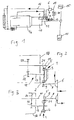
- the engine 14 drives via a transmission 10 drive wheels 15 of the vehicle.
- the transmission 10 can be designed for example as a manual transmission, automated manual or automatic transmission.
- a Retarder 1 is provided to brake the vehicle hydrodynamically.
- the rotor (not shown) of the retarder 1 is in a drive connection with the transmission output shaft 11, which in turn is in a drive connection with the drive wheels 15.
- a heat exchanger 7 is connected to the retarder 1, which on the one hand leads the cooling medium of the vehicle cooling circuit and on the other hand, the working medium of the retarder to transfer heat from the working medium of the retarder in the cooling medium of the cooling circuit.
- the working medium of the retarder may be in this case, for example, oil, water or a water mixture.
- the heat exchanger 7 leads in addition to the cooling medium of the cooling circuit and the working medium of the retarder 1, the working medium of a working medium circuit 17 of an expansion machine 6.
- the working medium of the expansion machine 6 is partially or completely condensed in the heat exchanger 7. Further components of the working medium circuit 17 of the expansion machine 6 are a reservoir 18 for the working medium, a feedwater pump 19 and an evaporator 20th
- the heat exchanger 7 could also be integrated in the working medium circuit 17 of the expansion machine 6 such that heat can be transferred from the working medium of the retarder 1 and / or from the cooling medium of the cooling circuit into the working medium of the expansion machine 6.
- the heat exchanger 7 would then be integrated in the flow direction behind the feed pump 19 and in front of the steam generator 20 in the working medium circuit 17 of the expansion machine 6.
- the working medium of the working medium circuit 17 of the expansion machine 6 at least behind the feedwater pump 19 has a certain pressure level, for example 6 - 10 bar
- the working medium of the expander 6 could serve as a control medium for the retarder 1 at the same time.
- suitable control valves would have to be provided in the working medium circuit 17, in order in turn to switch control valves of the retarder 1 or in the working medium circuit of the retarder 1 or to control or regulate.
- expansion machine 6 can either be used for driving the vehicle itself, that is to be used for traction of the vehicle, or for driving an aggregate, in particular auxiliary unit (not shown) of the vehicle. Alternatively or additionally, it is also possible, as described above, to drive a counter-rotating rotor (not shown) of the retarder 1 by means of the expansion machine 6.
- FIG. 2 can be seen a possible mechanical coupling of the expansion machine 6 via the rotor 2 of a retarder 1 to a transmission output shaft 11 of a transmission 10.
- FIG. 3 the possibility is shown schematically, the expansion machine 6 hydrodynamically coupled via a retarder 1, which can also be operated as a hydrodynamic coupling, to the transmission 10 and the transmission output shaft 11.
- This embodiment has the advantage that torsional vibrations, which may occur in the transmission 10, due to the torsional vibration damping effect of the hydrodynamic coupling not on the expansion machine 6, which can then be designed in particular as a turbine and at a very high speed, for example, up to 20,000 revolutions / Minute and more revolving, transferring. Furthermore, it is possible to drive the counter-rotating rotor 4 of the retarder 1 in opposite directions to the rotor 2 by means of the expansion machine 6 in order to increase the hydrodynamic braking action of the retarder.
- a toroidal working space 5 through the two paddle wheels - rotor 2 and stator 3 and rotor 2 and counter rotor 4 - formed which is optionally filled with a working medium. If this is desired, the braking torque of the hydrodynamic retarder 1 can be regulated via a degree of filling control. According to the embodiment with a mating retarder ( FIG. 3 However, a braking torque control via a speed adjustment of the expansion machine 6 is also possible.
- the expansion machine 6 has a drive shaft 8 which carries a pinion 9.
- the pinion 9 meshes with external teeth 21 either on the rotor 2 or the counter rotor 4 of the retarder 1.
- the rotor 2 of the retarder 1 is driven via a power take-off 12, that is a power take-off parallel to the main output, which forms the transmission output shaft 11, and present directly supported by the power take-off shaft 13 rotatably.
- the output shaft 13 is connected via a pinion 22 in a drive connection with the transmission output shaft 11.
- the pinion 22 of the PTO shaft 13 meshes with a gear 23 on the transmission output shaft eleventh
- the rotor 2 of the retarder with respect to the transmission output shaft 11 is translated into speed and compared to the expansion machine 6 and the drive shaft 8 of the expansion machine 6 translated into slow.
Landscapes
- Engineering & Computer Science (AREA)
- Chemical & Material Sciences (AREA)
- Combustion & Propulsion (AREA)
- Mechanical Engineering (AREA)
- General Engineering & Computer Science (AREA)
- Transmission Of Braking Force In Braking Systems (AREA)
- General Details Of Gearings (AREA)
- Compressors, Vaccum Pumps And Other Relevant Systems (AREA)
- Braking Arrangements (AREA)
- Auxiliary Drives, Propulsion Controls, And Safety Devices (AREA)
- Arrangement Of Transmissions (AREA)
- Hybrid Electric Vehicles (AREA)
- Motor Or Generator Cooling System (AREA)
- Electric Propulsion And Braking For Vehicles (AREA)
- Control Of Vehicle Engines Or Engines For Specific Uses (AREA)
Claims (5)
- Train d'entraînement de véhicule, en particulier d'un camion ou d'un véhicule sur rails, présentant un retardateur hydrodynamique (1), comprenant un rotor (2) et un stator (3) ou bien un rotor (2) et un contre-rotor (4), qui forment ensemble une chambre de travail (5) dans laquelle un écoulement circulaire de fluide de travail est formable, pour transmettre le couple de rotation du rotor (2) de manière hydrodynamique au stator (3) ou bien au contre-rotor (4), ou
présentant un retardateur dynamique, comprenant un rotor et un stator ou bien un rotor et un contre-rotor, pour transmettre le couple de rotation du rotor par une force magnétique, électrodynamiquement, par frottement du liquide ou frottement mécanique, où la transmission de couple de rotation ou bien une dissipation de la chaleur provenant du retardateur passe par un fluide de travail;
équipé d'un moteur à expansion (6) dans lequel le fluide ou la vapeur fait office de fluide de travail pour assurer son entraînement, par l'intermédiaire duquel une puissance d'entraînement mécanique peut être injectée dans le train d'entraînement ; caractérisé en ce qu'un échangeur thermique (7) est prévu, par le biais duquel le fluide de travail du retardateur (1) et le fluide de travail du moteur à expansion (6) sont guidés, pour évacuer la chaleur des deux fluides de travail et ainsi pour condenser le fluide de travail du moteur à expansion (6) partiellement ou complètement. - Train d'entraînement de véhicule automobile selon la revendication 1 caractérisé en ce que la transmission (10), en particulier la transmission manuelle, la boîte de vitesse automatique ou la transmission automatique est équipée d'un arbre d'entrée de transmission et/ou d'un arbre de sortie de transmission (11), permettant l'entraînement des roues motrices (15) du véhicule et la transmission (10) présente un entraînement auxiliaire (12) enclenché à une vitesse supérieure par rapport à l'arbre d'entrée de transmission et/ou l'arbre de sortie de transmission (11), par le biais duquel le rotor (2) du retardateur (1) est entraîné, où l'entraînement auxiliaire (12) présente notamment un arbre de sortie auxiliaire (13), portant le rotor (2) du retardateur (1) avec blocage en rotation.
- Train d'entraînement de véhicule selon l'une quelconque des revendications 1 ou 2, caractérisé en ce que le moteur à expansion (6) est une turbine, une visseuse ou une machine à piston.
- Train d'entraînement de véhicule selon l'une quelconque des revendications 1 à 3, caractérisé en ce que le retardateur (1) et le moteur à expansion (6) sont entourés d'un carter commun.
- Train d'entraînement de véhicule selon l'une quelconque des revendications 1 à 4, caractérisé en ce que le circuit de fluide de travail du moteur à expansion (6) contient un accumulateur notamment chauffé et/ou isolé thermiquement permettant le stockage de fluide de travail porté à température et en particulier sous forme de vapeur.
Applications Claiming Priority (2)
| Application Number | Priority Date | Filing Date | Title |
|---|---|---|---|
| DE102007006420A DE102007006420A1 (de) | 2007-02-05 | 2007-02-05 | Kraftfahrzeugantriebsstrang eines Kraftfahrzeugs mit einem Druckluftsystem |
| EP08707463.9A EP2109711B1 (fr) | 2007-02-05 | 2008-01-31 | Chaîne cinématique de véhicule pourvue d'un ralentisseur et d'une machine à expansion |
Related Parent Applications (2)
| Application Number | Title | Priority Date | Filing Date |
|---|---|---|---|
| EP08707463.9A Division-Into EP2109711B1 (fr) | 2007-02-05 | 2008-01-31 | Chaîne cinématique de véhicule pourvue d'un ralentisseur et d'une machine à expansion |
| EP08707463.9 Division | 2008-01-31 |
Publications (2)
| Publication Number | Publication Date |
|---|---|
| EP2474729A1 EP2474729A1 (fr) | 2012-07-11 |
| EP2474729B1 true EP2474729B1 (fr) | 2013-09-11 |
Family
ID=39148811
Family Applications (9)
| Application Number | Title | Priority Date | Filing Date |
|---|---|---|---|
| EP08707169A Not-in-force EP1987246B1 (fr) | 2007-02-05 | 2008-01-22 | Ensemble transmission d'un véhicule à moteur, pourvu d'un système à air comprimé |
| EP08019571A Not-in-force EP2025906B1 (fr) | 2007-02-05 | 2008-01-31 | Conducteur de commande, en particulier conducteur de commande de véhicule |
| EP12002461.7A Not-in-force EP2474730B1 (fr) | 2007-02-05 | 2008-01-31 | Conducteur de commande de véhicule avec un retardateur et une machine d'expansion |
| EP12002460.9A Not-in-force EP2474729B1 (fr) | 2007-02-05 | 2008-01-31 | Conducteur de commande de véhicule avec un retardateur et une machine d'expansion |
| EP13187869.6A Not-in-force EP2706217B1 (fr) | 2007-02-05 | 2008-01-31 | Chaîne cinématique de véhicule dotée d'un retardateur et d'une machine d'expansion |
| EP08707464A Withdrawn EP1999361A2 (fr) | 2007-02-05 | 2008-01-31 | Chaîne cinématique, en particulier chaîne cinématique de véhicule à moteur |
| EP08707463.9A Not-in-force EP2109711B1 (fr) | 2007-02-05 | 2008-01-31 | Chaîne cinématique de véhicule pourvue d'un ralentisseur et d'une machine à expansion |
| EP08707465.4A Not-in-force EP2094962B1 (fr) | 2007-02-05 | 2008-01-31 | Chaîne cinématique pourvue d'une machine à expansion à fluide ou à vapeur |
| EP10000669A Not-in-force EP2177742B1 (fr) | 2007-02-05 | 2008-01-31 | Conducteur de commande doté d'une machine d'expansion entraînée par du liquide ou de la vapeur |
Family Applications Before (3)
| Application Number | Title | Priority Date | Filing Date |
|---|---|---|---|
| EP08707169A Not-in-force EP1987246B1 (fr) | 2007-02-05 | 2008-01-22 | Ensemble transmission d'un véhicule à moteur, pourvu d'un système à air comprimé |
| EP08019571A Not-in-force EP2025906B1 (fr) | 2007-02-05 | 2008-01-31 | Conducteur de commande, en particulier conducteur de commande de véhicule |
| EP12002461.7A Not-in-force EP2474730B1 (fr) | 2007-02-05 | 2008-01-31 | Conducteur de commande de véhicule avec un retardateur et une machine d'expansion |
Family Applications After (5)
| Application Number | Title | Priority Date | Filing Date |
|---|---|---|---|
| EP13187869.6A Not-in-force EP2706217B1 (fr) | 2007-02-05 | 2008-01-31 | Chaîne cinématique de véhicule dotée d'un retardateur et d'une machine d'expansion |
| EP08707464A Withdrawn EP1999361A2 (fr) | 2007-02-05 | 2008-01-31 | Chaîne cinématique, en particulier chaîne cinématique de véhicule à moteur |
| EP08707463.9A Not-in-force EP2109711B1 (fr) | 2007-02-05 | 2008-01-31 | Chaîne cinématique de véhicule pourvue d'un ralentisseur et d'une machine à expansion |
| EP08707465.4A Not-in-force EP2094962B1 (fr) | 2007-02-05 | 2008-01-31 | Chaîne cinématique pourvue d'une machine à expansion à fluide ou à vapeur |
| EP10000669A Not-in-force EP2177742B1 (fr) | 2007-02-05 | 2008-01-31 | Conducteur de commande doté d'une machine d'expansion entraînée par du liquide ou de la vapeur |
Country Status (6)
| Country | Link |
|---|---|
| US (4) | US8261553B2 (fr) |
| EP (9) | EP1987246B1 (fr) |
| AT (3) | ATE548553T1 (fr) |
| BR (1) | BRPI0805840A2 (fr) |
| DE (2) | DE102007006420A1 (fr) |
| WO (4) | WO2008095599A1 (fr) |
Families Citing this family (38)
| Publication number | Priority date | Publication date | Assignee | Title |
|---|---|---|---|---|
| DE102007006420A1 (de) | 2007-02-05 | 2008-08-07 | Voith Patent Gmbh | Kraftfahrzeugantriebsstrang eines Kraftfahrzeugs mit einem Druckluftsystem |
| US20090277400A1 (en) * | 2008-05-06 | 2009-11-12 | Ronald David Conry | Rankine cycle heat recovery methods and devices |
| US20110226449A1 (en) * | 2008-10-01 | 2011-09-22 | Franz Mayr | Ventilation device for transmissions with lubricant comprising water |
| DE102008054637A1 (de) * | 2008-12-15 | 2010-06-17 | Zf Friedrichshafen Ag | Hybridantriebsstrang eines Kraftfahrzeugs |
| US9188027B2 (en) * | 2010-01-28 | 2015-11-17 | Ebara Corporation | Recovery system using fluid coupling on power generating system |
| DE102010045630A1 (de) * | 2010-09-17 | 2012-03-22 | Voith Patent Gmbh | Dampfgetriebener Kraftfahrzeugantriebsstrang |
| DE102011003487A1 (de) * | 2011-02-02 | 2012-08-02 | Bayerische Motoren Werke Aktiengesellschaft | Verfahren und Vorrichtung zur Nutzung der Abgasenergie einer Brennkraftmaschine |
| DE102011003607A1 (de) | 2011-02-03 | 2012-08-09 | Bayerische Motoren Werke Aktiengesellschaft | Verfahren und System zum Betreiben einer Expansionsmaschine mittels dem Abgas eines Verbrennungsmotors entzogener Wärmeleistung |
| DE102011017762A1 (de) | 2011-04-29 | 2012-10-31 | Zf Friedrichshafen Ag | Antriebsstrang eines Kraftfahrzeugs und Verfahren zu dessen Steuerung |
| DE102011076093A1 (de) * | 2011-05-19 | 2012-11-22 | Robert Bosch Gmbh | Vorrichtung und Verfahren zur Nutzung der Abwärme einer Brennkraftmaschine |
| DE102011117356A1 (de) * | 2011-10-29 | 2013-05-02 | Wabco Gmbh | Motorkoppeleinheit, insbesondere Hubkolbenmaschine, für einen Motor, Teil davon, Fahrzeug damit und Verfahren hierzu |
| DE102011120620B4 (de) * | 2011-12-09 | 2013-09-19 | Voith Patent Gmbh | Hydrodynamischer Retarder und Verfahren zum Betätigen eines solchen |
| DE102012004600A1 (de) * | 2012-03-07 | 2013-09-12 | Daimler Ag | Abwärmenutzungsvorrichtung für ein Kraftfahrzeug |
| DE102012204369B4 (de) | 2012-03-20 | 2015-10-29 | Robert Bosch Gmbh | Kraftmaschinenanordnung umfassend eine fluidbetätigte Kupplungsanordnung und eine Lamellenkupplung |
| US9067492B2 (en) | 2012-05-15 | 2015-06-30 | Zf Friedrichshafen Ag | Transmission with integrated PTO input gear damper |
| AT13244U1 (de) * | 2012-06-14 | 2013-09-15 | Avl List Gmbh | Nebenaggregatbaugruppe |
| DE102012014020A1 (de) | 2012-07-14 | 2014-01-16 | Wabco Gmbh | Kraftfahrzeug mit von einem Elektromotor angetriebenen Nebenaggregaten |
| US9162566B2 (en) | 2012-07-24 | 2015-10-20 | Zf Friedrichshafen Ag | PTO with integrated retarder |
| CN102843017B (zh) * | 2012-08-31 | 2014-12-10 | 柳州市京阳节能科技研发有限公司 | 铁道高效节能发电机组 |
| DE102012220893A1 (de) | 2012-11-15 | 2014-05-15 | Zf Friedrichshafen Ag | Fahrzeugantrieb mit einem Verbrennungsmotor und einer Abwärmenutzungseinheit |
| DE102012223024A1 (de) | 2012-12-13 | 2014-06-18 | Zf Friedrichshafen Ag | Abwärmenutzungseinheit für einen Fahrzeugantrieb |
| DE102013001657A1 (de) * | 2013-01-31 | 2014-07-31 | Man Truck & Bus Ag | Kühlkreislauf für ein Kraftfahrzeug mit einem hydrodynamischen Retarder |
| DE102013210595A1 (de) * | 2013-06-07 | 2014-12-11 | Voith Patent Gmbh | Schienenfahrzeug mit einem Dampfkraftprozess und Verwendung eines Dampfkraftprozesses in einem Schienenfahrzeug |
| DE102013219786A1 (de) * | 2013-09-30 | 2015-04-02 | Voith Patent Gmbh | Hydrauliksystem für eine hydrodynamische Maschine |
| DE102013224095A1 (de) * | 2013-11-26 | 2015-05-28 | Voith Patent Gmbh | Hydrodynamische Maschine |
| SE538407C2 (sv) * | 2014-04-09 | 2016-06-14 | Scania Cv Ab | Arrangemang i ett fordon som innefattar en retarder och ettWHR-system |
| FR3031363B1 (fr) * | 2015-01-07 | 2017-01-27 | Peugeot Citroen Automobiles Sa | Dispositif de recuperation d'energie thermique |
| US9932889B2 (en) * | 2015-10-01 | 2018-04-03 | Cummins Inc. | Lubrication system for waste heat recovery gear box |
| DE102016015270A1 (de) | 2016-12-21 | 2018-06-21 | Daimler Ag | Abwärmenutzungsvorrichtung |
| DE102016015271A1 (de) | 2016-12-21 | 2017-06-29 | Daimler Ag | Abwärmenutzungsvorrichtung |
| DE102017105613A1 (de) | 2017-03-16 | 2018-09-20 | Volkswagen Aktiengesellschaft | Kolbenmaschine und Kreisprozessvorrichtung |
| DE102018201110A1 (de) | 2017-04-06 | 2018-10-11 | Mahle International Gmbh | Kraftmaschinenanordnung |
| DE102017130318B4 (de) | 2017-12-18 | 2023-07-27 | Iav Gmbh Ingenieurgesellschaft Auto Und Verkehr | Kraftfahrzeugantrieb mit Energierückgewinnung |
| DE102018222245A1 (de) * | 2018-12-19 | 2020-06-25 | Robert Bosch Gmbh | Thermodynamischer Kreisprozess zur Erzeugung von Druckluft |
| CN111206990B (zh) * | 2019-01-15 | 2024-12-03 | 程建平 | 一种微型燃气轮发电增程器 |
| SE545034C2 (en) * | 2019-12-12 | 2023-03-07 | Scania Cv Ab | A powertrain and a vehicle comprising such a powertrain |
| KR102791585B1 (ko) * | 2020-09-11 | 2025-04-04 | 현대자동차주식회사 | 수소 연료전지 트럭의 보조제동장치 냉각 시스템 및 방법 |
| US12006869B2 (en) * | 2022-10-04 | 2024-06-11 | General Electric Company | Heat exchanger for a gas turbine engine |
Family Cites Families (74)
| Publication number | Priority date | Publication date | Assignee | Title |
|---|---|---|---|---|
| US2007032A (en) * | 1925-07-24 | 1935-07-02 | Wach Hans | Combined reciprocating engine and turbine |
| US1764061A (en) * | 1926-02-12 | 1930-06-17 | Wach Hans | Combined reciprocating engine and turbine |
| US1845087A (en) * | 1929-03-08 | 1932-02-16 | Westinghouse Electric & Mfg Co | Marine propulsion system |
| GB644759A (en) * | 1948-10-01 | 1950-10-18 | William Warren Triggs | Improvements in or relating to systems for utilising waste heat |
| US3171513A (en) * | 1963-01-24 | 1965-03-02 | Twin Disc Clutch Co | Hydrodynamic retarder |
| US3293944A (en) * | 1964-05-19 | 1966-12-27 | Twin Disc Clutch Co | Power transmission |
| US3605406A (en) * | 1969-06-27 | 1971-09-20 | Raymond L Woolley | Combined gas and steam power plant |
| DE2203319A1 (de) * | 1972-01-25 | 1973-08-02 | Daimler Benz Ag | Dauerbremse fuer fahrzeuge, insbesondere fuer kraftfahrzeuge, vornehmlich schwere nutzfahrzeuge |
| DE2214972A1 (de) * | 1972-03-28 | 1973-10-11 | Motoren Turbinen Union | Einrichtung zum bremsen von fahrzeugen mit gasturbinenantrieb |
| CA986727A (en) * | 1975-03-21 | 1976-04-06 | Ernst Eggmann | Hybrid motor unit with energy storage |
| DE2635154C2 (de) * | 1976-08-05 | 1984-07-26 | Alfred Teves Gmbh, 6000 Frankfurt | Drucksteuerventil für Fahrzeugbremsanlagen |
| US4182127A (en) * | 1977-12-12 | 1980-01-08 | Johnson Robert H | Power recovery and feedback system |
| US4197712A (en) * | 1978-04-21 | 1980-04-15 | Brigham William D | Fluid pumping and heating system |
| US4235320A (en) * | 1978-06-09 | 1980-11-25 | General Motors Corporation | Retarder and friction brakes |
| SE8003793L (sv) * | 1979-10-05 | 1981-04-06 | Wallace Murray Corp | Kombination av en konventionell forbrenningsmotor och en rankinecykelmotor |
| GB2080432B (en) | 1980-07-22 | 1984-03-14 | South Western Ind Res | Differential compound engine |
| JPS57206709A (en) * | 1981-06-15 | 1982-12-18 | Michio Shinba | Engine |
| DE3148208A1 (de) | 1981-12-05 | 1983-06-09 | Heinz 7410 Reutlingen Hafemann | Antriebseinrichtung aus verbrennungsmotor und dampfmotor |
| DE3245351A1 (de) * | 1982-12-08 | 1984-06-14 | Messerschmitt-Bölkow-Blohm GmbH, 8012 Ottobrunn | Antriebsvorrichtung fuer ein hilfsenergieerzeugungssystem eines schiffes |
| JPS59221409A (ja) * | 1983-05-30 | 1984-12-13 | Toyo Radiator Kk | エンジンにおける熱エネルギ−回収装置 |
| EP0161242A1 (fr) * | 1983-11-11 | 1985-11-21 | Jenbacher Werke AG | Dispositif d'entrainement |
| JPS60139538A (ja) * | 1983-12-27 | 1985-07-24 | Hino Motors Ltd | 自動車のリタ−ダ |
| DE3545660C1 (de) * | 1985-12-21 | 1987-06-25 | Voith Turbo Kg | Hydrodynamischer Stroemungskreislauf mit einer Einrichtung zur Reduktion der Luftventilationsleistung |
| US4754612A (en) * | 1987-04-24 | 1988-07-05 | Centrifugal Piston Expander, Inc. | Method for optimizing the mechanical output of a fluid pressure free piston engine |
| DE3866018D1 (de) * | 1987-05-22 | 1991-12-12 | Isuzu Motors Ltd | Motorbremssystem. |
| DE3832966A1 (de) * | 1988-09-29 | 1990-04-05 | Bosch Gmbh Robert | Heizvorrichtung fuer den fahrgastraum eines eine fluessigkeitsgekuehlte brennkraftmaschine aufweisenden kraftfahrzeuges |
| JP2534338B2 (ja) | 1988-12-09 | 1996-09-11 | 三菱重工業株式会社 | タ―ボコンパウンドエンジン |
| US5176000A (en) | 1990-12-11 | 1993-01-05 | Dauksis William P | Hybrid internal combustion engine/electrical motor ground vehicle propulsion system |
| US5121607A (en) | 1991-04-09 | 1992-06-16 | George Jr Leslie C | Energy recovery system for large motor vehicles |
| US5195881A (en) | 1991-04-09 | 1993-03-23 | George Jr Leslie C | Screw-type compressor/expander with valves at each axial end of rotors |
| US5241817A (en) * | 1991-04-09 | 1993-09-07 | George Jr Leslie C | Screw engine with regenerative braking |
| US5351487A (en) * | 1992-05-26 | 1994-10-04 | Abdelmalek Fawzy T | High efficiency natural gas engine driven cooling system |
| US5279262A (en) * | 1992-06-04 | 1994-01-18 | Muehleck Norman J | Mechanical liquid vaporizing waterbrake |
| JPH0688523A (ja) | 1992-09-08 | 1994-03-29 | Toyota Motor Corp | 内燃機関の廃熱回収装置 |
| US5683322A (en) * | 1993-04-21 | 1997-11-04 | Meyerle; Michael | Continuous hydrostatic-mechanical branch power split transmission particularly for power vehicles |
| IT1272684B (it) * | 1993-09-27 | 1997-06-26 | Gianluigi Reis | Sistema di ricupero energia dissipata, durante la sua marcia, da un veicolo a motore a combustione interna |
| DE4408349C2 (de) * | 1994-03-11 | 1995-08-31 | Voith Turbo Kg | Antriebseinheit mit einem Motor und einem Retarder |
| SE515966C2 (sv) * | 1994-06-20 | 2001-11-05 | Ranotor Utvecklings Ab | Motoraggregat omfattande en förbränningsmotor och en ångmotor |
| DE4435693A1 (de) * | 1994-10-06 | 1996-04-11 | Behr Gmbh & Co | Zusatzheizungs-Anordnung |
| DE59506087D1 (de) * | 1994-10-12 | 1999-07-08 | Voith Turbo Kg | Antriebseinheit mit einem Motor und einem Retarder |
| DE4445024A1 (de) * | 1994-12-16 | 1995-06-08 | Voith Turbo Kg | Antriebseinheit |
| DE4447166A1 (de) * | 1994-12-30 | 1995-06-08 | Voith Turbo Kg | Bremsanlage mit einem hydrodynamischen Retarder, insbesondere für ein Kraftfahrzeug |
| US6170264B1 (en) * | 1997-09-22 | 2001-01-09 | Clean Energy Systems, Inc. | Hydrocarbon combustion power generation system with CO2 sequestration |
| DE19641557A1 (de) * | 1996-10-09 | 1997-06-26 | Voith Turbo Kg | Antriebseinheit mit einem Motor, einem Getriebe und einem Kühlmittelkreislauf |
| DE19706090A1 (de) * | 1997-02-17 | 1998-08-20 | Lin Chion Dong | Antriebssystem für ein Kraftfahrzeug |
| DE19716299C1 (de) * | 1997-04-18 | 1998-02-12 | Zahnradfabrik Friedrichshafen | Blockheizkraftwerk |
| GB2333584A (en) * | 1998-01-23 | 1999-07-28 | S & C Thermofluids Ltd | Exhaust powered air conditioning system |
| DE19833891A1 (de) | 1998-07-28 | 2000-02-03 | Zahnradfabrik Friedrichshafen | Hydrodynamischer Retarder für ein Kraftfahrzeug |
| DE19939289C1 (de) * | 1999-08-19 | 2000-10-05 | Mak Motoren Gmbh & Co Kg | Verfahren und Einrichtung zur Aufbereitung von Gasgemischen |
| US6397694B2 (en) * | 1999-10-29 | 2002-06-04 | Caterpillar Inc. | Method and apparatus for calibrating a fluid retarder |
| JP2001227616A (ja) | 1999-12-08 | 2001-08-24 | Honda Motor Co Ltd | 駆動装置 |
| SE516921C2 (sv) * | 2000-05-31 | 2002-03-19 | Volvo Lastvagnar Ab | Reglerförfarande för tilluftsflödet till en förbränningsmotor samt reglerkrets för utförande av reglerförfarandet |
| US6450283B1 (en) * | 2000-11-27 | 2002-09-17 | Michael Blake Taggett | Waste heat conversion system |
| DE10103403C5 (de) * | 2001-01-26 | 2004-07-29 | Ballard Power Systems Ag | Fahrzeug mit Dampfmaschine |
| DE10290840B4 (de) * | 2001-03-01 | 2007-07-26 | Voith Turbo Gmbh & Co. Kg | Antriebseinheit mit einem Verbrennungsmotor und einem Abgasturbolader |
| DE10143342A1 (de) | 2001-09-04 | 2003-04-03 | Herfried Wichern | Kopplung von Verbrennungskraftmaschinen |
| US7475541B2 (en) * | 2001-10-09 | 2009-01-13 | Honda Giken Kogyo Kabushiki Kaisha | Rankine cycle system and vehicle therewith |
| DE10158436A1 (de) * | 2001-11-29 | 2003-06-12 | Behr Gmbh & Co | Wärmetauscher |
| DE10221157A1 (de) * | 2002-05-13 | 2003-12-04 | Manfred Nixdorf | Anordnung und Verfahren zur Leistungserhöhung eines Verbrennungsmotors |
| US7454910B2 (en) * | 2003-06-23 | 2008-11-25 | Denso Corporation | Waste heat recovery system of heat source, with Rankine cycle |
| DE10332907A1 (de) * | 2003-07-19 | 2005-02-17 | Voith Turbo Gmbh & Co. Kg | Kraftfahrzeugkühlmittelkreislauf mit Pumpe und Retarder |
| DE10360155A1 (de) * | 2003-12-20 | 2005-07-21 | Voith Turbo Gmbh & Co. Kg | Antriebsstrang mit Abgasnutzung und Steuerungsverfahren |
| US7866380B2 (en) * | 2005-04-05 | 2011-01-11 | Omnitherm, Inc. | System and method for producing hot water without a flame |
| DE102005037640A1 (de) * | 2005-08-05 | 2007-02-08 | Voith Turbo Gmbh & Co. Kg | Antriebsstrang |
| US7454911B2 (en) * | 2005-11-04 | 2008-11-25 | Tafas Triantafyllos P | Energy recovery system in an engine |
| DE102006008110A1 (de) | 2006-02-20 | 2007-08-30 | Voith Turbo Gmbh & Co. Kg | Füllungssteuervorrichtung für eine hydrodynamische Maschine |
| JP4816143B2 (ja) | 2006-03-01 | 2011-11-16 | トヨタ自動車株式会社 | 排熱回収装置 |
| US7614367B1 (en) * | 2006-05-15 | 2009-11-10 | F. Alan Frick | Method and apparatus for heating, concentrating and evaporating fluid |
| US8371251B2 (en) * | 2006-04-24 | 2013-02-12 | Phoenix Caliente Llc | Methods and apparatuses for heating, concentrating and evaporating fluid |
| DE102007006420A1 (de) | 2007-02-05 | 2008-08-07 | Voith Patent Gmbh | Kraftfahrzeugantriebsstrang eines Kraftfahrzeugs mit einem Druckluftsystem |
| US8215437B2 (en) * | 2008-03-17 | 2012-07-10 | Icr Turbine Engine Corporation | Regenerative braking for gas turbine systems |
| DE102009005504A1 (de) * | 2009-01-19 | 2010-07-22 | Voith Patent Gmbh | Fahrzeugkühlkreislauf mit einem Retarder oder einer hydrodynamischen Kupplung |
| DE102009035861B3 (de) * | 2009-07-31 | 2011-02-24 | Voith Patent Gmbh | Antriebsvorrichtung und Verfahren für deren Betrieb |
| DE102010007149B4 (de) | 2010-02-05 | 2011-09-01 | Voith Patent Gmbh | Füllsteuerungsvorrichtung für eine hydrodynamische Maschine |
-
2007
- 2007-02-05 DE DE102007006420A patent/DE102007006420A1/de not_active Withdrawn
-
2008
- 2008-01-22 WO PCT/EP2008/000436 patent/WO2008095599A1/fr not_active Ceased
- 2008-01-22 EP EP08707169A patent/EP1987246B1/fr not_active Not-in-force
- 2008-01-22 BR BRPI0805840-7A patent/BRPI0805840A2/pt not_active IP Right Cessation
- 2008-01-22 AT AT08707169T patent/ATE548553T1/de active
- 2008-01-31 EP EP08019571A patent/EP2025906B1/fr not_active Not-in-force
- 2008-01-31 DE DE112008000212T patent/DE112008000212A5/de not_active Withdrawn
- 2008-01-31 WO PCT/EP2008/000776 patent/WO2008095640A2/fr not_active Ceased
- 2008-01-31 EP EP12002461.7A patent/EP2474730B1/fr not_active Not-in-force
- 2008-01-31 AT AT10000669T patent/ATE531921T1/de active
- 2008-01-31 EP EP12002460.9A patent/EP2474729B1/fr not_active Not-in-force
- 2008-01-31 WO PCT/EP2008/000778 patent/WO2008095642A1/fr not_active Ceased
- 2008-01-31 WO PCT/EP2008/000777 patent/WO2008095641A2/fr not_active Ceased
- 2008-01-31 AT AT08019571T patent/ATE556210T1/de active
- 2008-01-31 EP EP13187869.6A patent/EP2706217B1/fr not_active Not-in-force
- 2008-01-31 US US12/449,277 patent/US8261553B2/en not_active Expired - Fee Related
- 2008-01-31 EP EP08707464A patent/EP1999361A2/fr not_active Withdrawn
- 2008-01-31 US US12/449,276 patent/US20100050635A1/en not_active Abandoned
- 2008-01-31 EP EP08707463.9A patent/EP2109711B1/fr not_active Not-in-force
- 2008-01-31 EP EP08707465.4A patent/EP2094962B1/fr not_active Not-in-force
- 2008-01-31 EP EP10000669A patent/EP2177742B1/fr not_active Not-in-force
-
2009
- 2009-02-26 US US12/393,517 patent/US8359860B2/en not_active Expired - Fee Related
- 2009-02-26 US US12/393,440 patent/US8857181B2/en not_active Expired - Fee Related
Also Published As
Similar Documents
| Publication | Publication Date | Title |
|---|---|---|
| EP2109711B1 (fr) | Chaîne cinématique de véhicule pourvue d'un ralentisseur et d'une machine à expansion | |
| EP2480438B1 (fr) | Ensemble de transmission avec un ralentisseur hydrodynamique | |
| EP3810448B1 (fr) | Unité d'entraînement destinée à la chaîne cinématique d'un véhicule automobile à entraînement électrique et système d'entraînement muni de ladite unité d'entraînement | |
| DE102004002215B3 (de) | Antriebskraftübertragungsvorrichtung mit hydrodynamischer Gegenlaufkupplung | |
| EP3074654B1 (fr) | Machine hydrodynamique | |
| DE4445024A1 (de) | Antriebseinheit | |
| DE102009028153A1 (de) | Antriebseinrichtung mit einem Verbrennungsmotor und einer eine Verlustwärme nutzenden Expansionsmaschine | |
| DE102007038236A1 (de) | Kraftfahrzeug-Anfahrelement und Verfahren zum Antreiben eines Kraftfahrzeugs | |
| WO2013083322A1 (fr) | Chaîne cinématique pour un véhicule à moteur comportant un ralentisseur hydrodynamique | |
| DE102013225954B3 (de) | Kraftfahrzeugantriebsstrang mit einer im Abgasstrom positionierten Nutzturbine | |
| WO2015078579A2 (fr) | Machine hydrodynamique pourvue d'un dispositif d'accouplement | |
| WO2009090075A1 (fr) | Système turbocompresseur-turborécupérateur | |
| DE102006030041A1 (de) | Pumpenvorrichtung eines Fahrzeuggetriebes | |
| EP2166254B1 (fr) | Train d'entraînement dans un véhicule | |
| EP1944184A1 (fr) | Unité d'entraînement hybride dotée d'un moteur à combustion interne et d'une machine à vapeur | |
| WO2014108513A1 (fr) | Chaîne cinématique pourvue d'un retardateur hydrodynamique et d'un moteur électrique | |
| DE102015211485A1 (de) | Getriebe mit elektrischer Maschine und zuschaltbarem Retarder | |
| DE102006013003B3 (de) | Hydrodynamische Baugruppe mit einem Retarder und einer hydrodynamischen Kupplung | |
| EP2998176B1 (fr) | Dispositif de frein permanent pour entrainement d'un vehicule automobile et entrainement d'un vehicule automobile | |
| WO2014108309A2 (fr) | Chaîne cinématique comprenant un ralentisseur hydrodynamique et un moteur électrique |
Legal Events
| Date | Code | Title | Description |
|---|---|---|---|
| PUAI | Public reference made under article 153(3) epc to a published international application that has entered the european phase |
Free format text: ORIGINAL CODE: 0009012 |
|
| AC | Divisional application: reference to earlier application |
Ref document number: 2109711 Country of ref document: EP Kind code of ref document: P |
|
| AK | Designated contracting states |
Kind code of ref document: A1 Designated state(s): AT BE BG CH CY CZ DE DK EE ES FI FR GB GR HR HU IE IS IT LI LT LU LV MC MT NL NO PL PT RO SE SI SK TR |
|
| 17P | Request for examination filed |
Effective date: 20120614 |
|
| RIN1 | Information on inventor provided before grant (corrected) |
Inventor name: PITTIUS, DR. REINHOLD Inventor name: BARTOSCH, STEPHAN |
|
| 17Q | First examination report despatched |
Effective date: 20130111 |
|
| GRAP | Despatch of communication of intention to grant a patent |
Free format text: ORIGINAL CODE: EPIDOSNIGR1 |
|
| INTG | Intention to grant announced |
Effective date: 20130503 |
|
| GRAS | Grant fee paid |
Free format text: ORIGINAL CODE: EPIDOSNIGR3 |
|
| GRAA | (expected) grant |
Free format text: ORIGINAL CODE: 0009210 |
|
| AC | Divisional application: reference to earlier application |
Ref document number: 2109711 Country of ref document: EP Kind code of ref document: P |
|
| AK | Designated contracting states |
Kind code of ref document: B1 Designated state(s): AT BE BG CH CY CZ DE DK EE ES FI FR GB GR HR HU IE IS IT LI LT LU LV MC MT NL NO PL PT RO SE SI SK TR |
|
| REG | Reference to a national code |
Ref country code: GB Ref legal event code: FG4D Free format text: NOT ENGLISH |
|
| REG | Reference to a national code |
Ref country code: CH Ref legal event code: EP |
|
| REG | Reference to a national code |
Ref country code: AT Ref legal event code: REF Ref document number: 631773 Country of ref document: AT Kind code of ref document: T Effective date: 20130915 |
|
| REG | Reference to a national code |
Ref country code: IE Ref legal event code: FG4D Free format text: LANGUAGE OF EP DOCUMENT: GERMAN |
|
| REG | Reference to a national code |
Ref country code: DE Ref legal event code: R096 Ref document number: 502008010661 Country of ref document: DE Effective date: 20131031 |
|
| PG25 | Lapsed in a contracting state [announced via postgrant information from national office to epo] |
Ref country code: HR Free format text: LAPSE BECAUSE OF FAILURE TO SUBMIT A TRANSLATION OF THE DESCRIPTION OR TO PAY THE FEE WITHIN THE PRESCRIBED TIME-LIMIT Effective date: 20130911 Ref country code: CY Free format text: LAPSE BECAUSE OF FAILURE TO SUBMIT A TRANSLATION OF THE DESCRIPTION OR TO PAY THE FEE WITHIN THE PRESCRIBED TIME-LIMIT Effective date: 20130904 Ref country code: LT Free format text: LAPSE BECAUSE OF FAILURE TO SUBMIT A TRANSLATION OF THE DESCRIPTION OR TO PAY THE FEE WITHIN THE PRESCRIBED TIME-LIMIT Effective date: 20130911 Ref country code: NO Free format text: LAPSE BECAUSE OF FAILURE TO SUBMIT A TRANSLATION OF THE DESCRIPTION OR TO PAY THE FEE WITHIN THE PRESCRIBED TIME-LIMIT Effective date: 20131211 Ref country code: SE Free format text: LAPSE BECAUSE OF FAILURE TO SUBMIT A TRANSLATION OF THE DESCRIPTION OR TO PAY THE FEE WITHIN THE PRESCRIBED TIME-LIMIT Effective date: 20130911 |
|
| REG | Reference to a national code |
Ref country code: NL Ref legal event code: VDEP Effective date: 20130911 |
|
| REG | Reference to a national code |
Ref country code: LT Ref legal event code: MG4D |
|
| PG25 | Lapsed in a contracting state [announced via postgrant information from national office to epo] |
Ref country code: LV Free format text: LAPSE BECAUSE OF FAILURE TO SUBMIT A TRANSLATION OF THE DESCRIPTION OR TO PAY THE FEE WITHIN THE PRESCRIBED TIME-LIMIT Effective date: 20130911 Ref country code: FI Free format text: LAPSE BECAUSE OF FAILURE TO SUBMIT A TRANSLATION OF THE DESCRIPTION OR TO PAY THE FEE WITHIN THE PRESCRIBED TIME-LIMIT Effective date: 20130911 Ref country code: SI Free format text: LAPSE BECAUSE OF FAILURE TO SUBMIT A TRANSLATION OF THE DESCRIPTION OR TO PAY THE FEE WITHIN THE PRESCRIBED TIME-LIMIT Effective date: 20130911 Ref country code: GR Free format text: LAPSE BECAUSE OF FAILURE TO SUBMIT A TRANSLATION OF THE DESCRIPTION OR TO PAY THE FEE WITHIN THE PRESCRIBED TIME-LIMIT Effective date: 20131212 |
|
| PG25 | Lapsed in a contracting state [announced via postgrant information from national office to epo] |
Ref country code: CY Free format text: LAPSE BECAUSE OF FAILURE TO SUBMIT A TRANSLATION OF THE DESCRIPTION OR TO PAY THE FEE WITHIN THE PRESCRIBED TIME-LIMIT Effective date: 20130911 |
|
| PG25 | Lapsed in a contracting state [announced via postgrant information from national office to epo] |
Ref country code: EE Free format text: LAPSE BECAUSE OF FAILURE TO SUBMIT A TRANSLATION OF THE DESCRIPTION OR TO PAY THE FEE WITHIN THE PRESCRIBED TIME-LIMIT Effective date: 20130911 Ref country code: CZ Free format text: LAPSE BECAUSE OF FAILURE TO SUBMIT A TRANSLATION OF THE DESCRIPTION OR TO PAY THE FEE WITHIN THE PRESCRIBED TIME-LIMIT Effective date: 20130911 Ref country code: NL Free format text: LAPSE BECAUSE OF FAILURE TO SUBMIT A TRANSLATION OF THE DESCRIPTION OR TO PAY THE FEE WITHIN THE PRESCRIBED TIME-LIMIT Effective date: 20130911 Ref country code: RO Free format text: LAPSE BECAUSE OF FAILURE TO SUBMIT A TRANSLATION OF THE DESCRIPTION OR TO PAY THE FEE WITHIN THE PRESCRIBED TIME-LIMIT Effective date: 20130911 Ref country code: SK Free format text: LAPSE BECAUSE OF FAILURE TO SUBMIT A TRANSLATION OF THE DESCRIPTION OR TO PAY THE FEE WITHIN THE PRESCRIBED TIME-LIMIT Effective date: 20130911 Ref country code: IS Free format text: LAPSE BECAUSE OF FAILURE TO SUBMIT A TRANSLATION OF THE DESCRIPTION OR TO PAY THE FEE WITHIN THE PRESCRIBED TIME-LIMIT Effective date: 20140111 |
|
| REG | Reference to a national code |
Ref country code: DE Ref legal event code: R082 Ref document number: 502008010661 Country of ref document: DE Representative=s name: DR. WEITZEL & PARTNER PATENT- UND RECHTSANWAEL, DE |
|
| PG25 | Lapsed in a contracting state [announced via postgrant information from national office to epo] |
Ref country code: PL Free format text: LAPSE BECAUSE OF FAILURE TO SUBMIT A TRANSLATION OF THE DESCRIPTION OR TO PAY THE FEE WITHIN THE PRESCRIBED TIME-LIMIT Effective date: 20130911 Ref country code: ES Free format text: LAPSE BECAUSE OF FAILURE TO SUBMIT A TRANSLATION OF THE DESCRIPTION OR TO PAY THE FEE WITHIN THE PRESCRIBED TIME-LIMIT Effective date: 20130911 |
|
| PGFP | Annual fee paid to national office [announced via postgrant information from national office to epo] |
Ref country code: AT Payment date: 20140121 Year of fee payment: 7 |
|
| REG | Reference to a national code |
Ref country code: DE Ref legal event code: R097 Ref document number: 502008010661 Country of ref document: DE |
|
| REG | Reference to a national code |
Ref country code: DE Ref legal event code: R082 Ref document number: 502008010661 Country of ref document: DE Representative=s name: DR. WEITZEL & PARTNER PATENT- UND RECHTSANWAEL, DE Effective date: 20140520 Ref country code: DE Ref legal event code: R081 Ref document number: 502008010661 Country of ref document: DE Owner name: STEAMDRIVE GMBH, DE Free format text: FORMER OWNER: VOITH PATENT GMBH, 89522 HEIDENHEIM, DE Effective date: 20140520 |
|
| PG25 | Lapsed in a contracting state [announced via postgrant information from national office to epo] |
Ref country code: PT Free format text: LAPSE BECAUSE OF FAILURE TO SUBMIT A TRANSLATION OF THE DESCRIPTION OR TO PAY THE FEE WITHIN THE PRESCRIBED TIME-LIMIT Effective date: 20140113 |
|
| PGFP | Annual fee paid to national office [announced via postgrant information from national office to epo] |
Ref country code: GB Payment date: 20140123 Year of fee payment: 7 |
|
| PLBE | No opposition filed within time limit |
Free format text: ORIGINAL CODE: 0009261 |
|
| STAA | Information on the status of an ep patent application or granted ep patent |
Free format text: STATUS: NO OPPOSITION FILED WITHIN TIME LIMIT |
|
| BERE | Be: lapsed |
Owner name: VOITH PATENT G.M.B.H. Effective date: 20140131 |
|
| 26N | No opposition filed |
Effective date: 20140612 |
|
| PG25 | Lapsed in a contracting state [announced via postgrant information from national office to epo] |
Ref country code: IT Free format text: LAPSE BECAUSE OF FAILURE TO SUBMIT A TRANSLATION OF THE DESCRIPTION OR TO PAY THE FEE WITHIN THE PRESCRIBED TIME-LIMIT Effective date: 20130911 Ref country code: LU Free format text: LAPSE BECAUSE OF FAILURE TO SUBMIT A TRANSLATION OF THE DESCRIPTION OR TO PAY THE FEE WITHIN THE PRESCRIBED TIME-LIMIT Effective date: 20140131 |
|
| REG | Reference to a national code |
Ref country code: CH Ref legal event code: PL Ref country code: FR Ref legal event code: TP Owner name: STEAMDRIVE GMBH, DE Effective date: 20140731 |
|
| REG | Reference to a national code |
Ref country code: GB Ref legal event code: 732E Free format text: REGISTERED BETWEEN 20140821 AND 20140827 |
|
| REG | Reference to a national code |
Ref country code: DE Ref legal event code: R097 Ref document number: 502008010661 Country of ref document: DE Effective date: 20140612 |
|
| PG25 | Lapsed in a contracting state [announced via postgrant information from national office to epo] |
Ref country code: DK Free format text: LAPSE BECAUSE OF FAILURE TO SUBMIT A TRANSLATION OF THE DESCRIPTION OR TO PAY THE FEE WITHIN THE PRESCRIBED TIME-LIMIT Effective date: 20130911 |
|
| PG25 | Lapsed in a contracting state [announced via postgrant information from national office to epo] |
Ref country code: CH Free format text: LAPSE BECAUSE OF NON-PAYMENT OF DUE FEES Effective date: 20140131 Ref country code: LI Free format text: LAPSE BECAUSE OF NON-PAYMENT OF DUE FEES Effective date: 20140131 |
|
| REG | Reference to a national code |
Ref country code: IE Ref legal event code: MM4A |
|
| REG | Reference to a national code |
Ref country code: AT Ref legal event code: PC Ref document number: 631773 Country of ref document: AT Kind code of ref document: T Owner name: STEAMDRIVE GMBH, DE Effective date: 20141114 |
|
| PG25 | Lapsed in a contracting state [announced via postgrant information from national office to epo] |
Ref country code: IE Free format text: LAPSE BECAUSE OF NON-PAYMENT OF DUE FEES Effective date: 20140131 Ref country code: BE Free format text: LAPSE BECAUSE OF NON-PAYMENT OF DUE FEES Effective date: 20140131 |
|
| REG | Reference to a national code |
Ref country code: FR Ref legal event code: PLFP Year of fee payment: 8 |
|
| PG25 | Lapsed in a contracting state [announced via postgrant information from national office to epo] |
Ref country code: MC Free format text: LAPSE BECAUSE OF FAILURE TO SUBMIT A TRANSLATION OF THE DESCRIPTION OR TO PAY THE FEE WITHIN THE PRESCRIBED TIME-LIMIT Effective date: 20130911 |
|
| PGFP | Annual fee paid to national office [announced via postgrant information from national office to epo] |
Ref country code: FR Payment date: 20150130 Year of fee payment: 8 |
|
| REG | Reference to a national code |
Ref country code: AT Ref legal event code: MM01 Ref document number: 631773 Country of ref document: AT Kind code of ref document: T Effective date: 20150131 |
|
| GBPC | Gb: european patent ceased through non-payment of renewal fee |
Effective date: 20150131 |
|
| PG25 | Lapsed in a contracting state [announced via postgrant information from national office to epo] |
Ref country code: GB Free format text: LAPSE BECAUSE OF NON-PAYMENT OF DUE FEES Effective date: 20150131 |
|
| PG25 | Lapsed in a contracting state [announced via postgrant information from national office to epo] |
Ref country code: AT Free format text: LAPSE BECAUSE OF NON-PAYMENT OF DUE FEES Effective date: 20150131 |
|
| PG25 | Lapsed in a contracting state [announced via postgrant information from national office to epo] |
Ref country code: MT Free format text: LAPSE BECAUSE OF FAILURE TO SUBMIT A TRANSLATION OF THE DESCRIPTION OR TO PAY THE FEE WITHIN THE PRESCRIBED TIME-LIMIT Effective date: 20130911 |
|
| PG25 | Lapsed in a contracting state [announced via postgrant information from national office to epo] |
Ref country code: BG Free format text: LAPSE BECAUSE OF FAILURE TO SUBMIT A TRANSLATION OF THE DESCRIPTION OR TO PAY THE FEE WITHIN THE PRESCRIBED TIME-LIMIT Effective date: 20130911 |
|
| PG25 | Lapsed in a contracting state [announced via postgrant information from national office to epo] |
Ref country code: HU Free format text: LAPSE BECAUSE OF FAILURE TO SUBMIT A TRANSLATION OF THE DESCRIPTION OR TO PAY THE FEE WITHIN THE PRESCRIBED TIME-LIMIT; INVALID AB INITIO Effective date: 20080131 Ref country code: TR Free format text: LAPSE BECAUSE OF FAILURE TO SUBMIT A TRANSLATION OF THE DESCRIPTION OR TO PAY THE FEE WITHIN THE PRESCRIBED TIME-LIMIT Effective date: 20130911 |
|
| REG | Reference to a national code |
Ref country code: FR Ref legal event code: ST Effective date: 20160930 |
|
| PG25 | Lapsed in a contracting state [announced via postgrant information from national office to epo] |
Ref country code: FR Free format text: LAPSE BECAUSE OF NON-PAYMENT OF DUE FEES Effective date: 20160201 |
|
| PGFP | Annual fee paid to national office [announced via postgrant information from national office to epo] |
Ref country code: DE Payment date: 20180205 Year of fee payment: 11 |
|
| REG | Reference to a national code |
Ref country code: DE Ref legal event code: R119 Ref document number: 502008010661 Country of ref document: DE |
|
| PG25 | Lapsed in a contracting state [announced via postgrant information from national office to epo] |
Ref country code: DE Free format text: LAPSE BECAUSE OF NON-PAYMENT OF DUE FEES Effective date: 20190801 |