EP2474853B1 - Elektronisches Endoskopsystem - Google Patents
Elektronisches Endoskopsystem Download PDFInfo
- Publication number
- EP2474853B1 EP2474853B1 EP11186707.3A EP11186707A EP2474853B1 EP 2474853 B1 EP2474853 B1 EP 2474853B1 EP 11186707 A EP11186707 A EP 11186707A EP 2474853 B1 EP2474853 B1 EP 2474853B1
- Authority
- EP
- European Patent Office
- Prior art keywords
- objects
- reflection spectra
- irrelevant objects
- irrelevant
- spectra
- Prior art date
- Legal status (The legal status is an assumption and is not a legal conclusion. Google has not performed a legal analysis and makes no representation as to the accuracy of the status listed.)
- Active
Links
- 238000001228 spectrum Methods 0.000 claims description 125
- 230000002792 vascular Effects 0.000 claims description 64
- 238000000862 absorption spectrum Methods 0.000 claims description 49
- 238000007689 inspection Methods 0.000 claims description 47
- 230000003595 spectral effect Effects 0.000 claims description 37
- 238000012360 testing method Methods 0.000 claims description 23
- 210000004369 blood Anatomy 0.000 claims description 20
- 239000008280 blood Substances 0.000 claims description 20
- 210000004204 blood vessel Anatomy 0.000 claims description 20
- 102000001554 Hemoglobins Human genes 0.000 claims description 16
- 108010054147 Hemoglobins Proteins 0.000 claims description 16
- 238000003384 imaging method Methods 0.000 claims description 14
- 238000000611 regression analysis Methods 0.000 claims description 14
- 239000000463 material Substances 0.000 claims description 11
- 238000010186 staining Methods 0.000 claims description 10
- 239000000126 substance Substances 0.000 claims description 8
- 230000003287 optical effect Effects 0.000 claims description 6
- 230000004044 response Effects 0.000 claims description 6
- 230000028327 secretion Effects 0.000 claims description 5
- 230000006870 function Effects 0.000 claims description 2
- 238000001444 catalytic combustion detection Methods 0.000 description 41
- QVGXLLKOCUKJST-UHFFFAOYSA-N atomic oxygen Chemical compound [O] QVGXLLKOCUKJST-UHFFFAOYSA-N 0.000 description 19
- 229910052760 oxygen Inorganic materials 0.000 description 19
- 239000001301 oxygen Substances 0.000 description 19
- 238000003379 elimination reaction Methods 0.000 description 17
- 238000012545 processing Methods 0.000 description 16
- 238000005286 illumination Methods 0.000 description 13
- 238000000034 method Methods 0.000 description 13
- 230000008030 elimination Effects 0.000 description 11
- 210000000941 bile Anatomy 0.000 description 10
- 230000000875 corresponding effect Effects 0.000 description 9
- 238000010586 diagram Methods 0.000 description 9
- 230000035945 sensitivity Effects 0.000 description 9
- 238000011156 evaluation Methods 0.000 description 7
- 230000008569 process Effects 0.000 description 7
- 238000005259 measurement Methods 0.000 description 6
- 230000005540 biological transmission Effects 0.000 description 5
- 238000004364 calculation method Methods 0.000 description 4
- 238000012937 correction Methods 0.000 description 4
- 230000003902 lesion Effects 0.000 description 4
- 239000002131 composite material Substances 0.000 description 3
- 239000004973 liquid crystal related substance Substances 0.000 description 3
- 229910052724 xenon Inorganic materials 0.000 description 3
- FHNFHKCVQCLJFQ-UHFFFAOYSA-N xenon atom Chemical compound [Xe] FHNFHKCVQCLJFQ-UHFFFAOYSA-N 0.000 description 3
- 241001025261 Neoraja caerulea Species 0.000 description 2
- 238000009825 accumulation Methods 0.000 description 2
- 230000003321 amplification Effects 0.000 description 2
- BJQHLKABXJIVAM-UHFFFAOYSA-N bis(2-ethylhexyl) phthalate Chemical compound CCCCC(CC)COC(=O)C1=CC=CC=C1C(=O)OCC(CC)CCCC BJQHLKABXJIVAM-UHFFFAOYSA-N 0.000 description 2
- 230000008859 change Effects 0.000 description 2
- 238000004040 coloring Methods 0.000 description 2
- 230000001276 controlling effect Effects 0.000 description 2
- 230000002596 correlated effect Effects 0.000 description 2
- 210000002858 crystal cell Anatomy 0.000 description 2
- 238000003745 diagnosis Methods 0.000 description 2
- KHLVKKOJDHCJMG-QDBORUFSSA-L indigo carmine Chemical compound [Na+].[Na+].N/1C2=CC=C(S([O-])(=O)=O)C=C2C(=O)C\1=C1/NC2=CC=C(S(=O)(=O)[O-])C=C2C1=O KHLVKKOJDHCJMG-QDBORUFSSA-L 0.000 description 2
- 229960003988 indigo carmine Drugs 0.000 description 2
- 235000012738 indigotine Nutrition 0.000 description 2
- 239000004179 indigotine Substances 0.000 description 2
- 238000003199 nucleic acid amplification method Methods 0.000 description 2
- 238000005070 sampling Methods 0.000 description 2
- 238000000926 separation method Methods 0.000 description 2
- 210000001519 tissue Anatomy 0.000 description 2
- 238000002834 transmittance Methods 0.000 description 2
- XLYOFNOQVPJJNP-UHFFFAOYSA-N water Substances O XLYOFNOQVPJJNP-UHFFFAOYSA-N 0.000 description 2
- 239000004988 Nematic liquid crystal Substances 0.000 description 1
- OAICVXFJPJFONN-UHFFFAOYSA-N Phosphorus Chemical compound [P] OAICVXFJPJFONN-UHFFFAOYSA-N 0.000 description 1
- 230000002411 adverse Effects 0.000 description 1
- 238000007664 blowing Methods 0.000 description 1
- 238000006243 chemical reaction Methods 0.000 description 1
- 239000003086 colorant Substances 0.000 description 1
- 238000010168 coupling process Methods 0.000 description 1
- 239000013078 crystal Substances 0.000 description 1
- 230000004069 differentiation Effects 0.000 description 1
- 230000009189 diving Effects 0.000 description 1
- 229940079593 drug Drugs 0.000 description 1
- 239000003814 drug Substances 0.000 description 1
- 238000001839 endoscopy Methods 0.000 description 1
- 210000003743 erythrocyte Anatomy 0.000 description 1
- 229910052736 halogen Inorganic materials 0.000 description 1
- 150000002367 halogens Chemical class 0.000 description 1
- PNDPGZBMCMUPRI-UHFFFAOYSA-N iodine Chemical compound II PNDPGZBMCMUPRI-UHFFFAOYSA-N 0.000 description 1
- 230000000873 masking effect Effects 0.000 description 1
- 239000011159 matrix material Substances 0.000 description 1
- 229910001507 metal halide Inorganic materials 0.000 description 1
- 150000005309 metal halides Chemical class 0.000 description 1
- 238000012986 modification Methods 0.000 description 1
- 230000004048 modification Effects 0.000 description 1
- 239000013307 optical fiber Substances 0.000 description 1
- 230000007170 pathology Effects 0.000 description 1
- 210000002381 plasma Anatomy 0.000 description 1
- 230000009467 reduction Effects 0.000 description 1
- 239000004065 semiconductor Substances 0.000 description 1
- 239000000758 substrate Substances 0.000 description 1
- 210000001835 viscera Anatomy 0.000 description 1
Images





Classifications
-
- A—HUMAN NECESSITIES
- A61—MEDICAL OR VETERINARY SCIENCE; HYGIENE
- A61B—DIAGNOSIS; SURGERY; IDENTIFICATION
- A61B5/00—Measuring for diagnostic purposes; Identification of persons
- A61B5/0059—Measuring for diagnostic purposes; Identification of persons using light, e.g. diagnosis by transillumination, diascopy, fluorescence
- A61B5/0082—Measuring for diagnostic purposes; Identification of persons using light, e.g. diagnosis by transillumination, diascopy, fluorescence adapted for particular medical purposes
- A61B5/0084—Measuring for diagnostic purposes; Identification of persons using light, e.g. diagnosis by transillumination, diascopy, fluorescence adapted for particular medical purposes for introduction into the body, e.g. by catheters
-
- A—HUMAN NECESSITIES
- A61—MEDICAL OR VETERINARY SCIENCE; HYGIENE
- A61B—DIAGNOSIS; SURGERY; IDENTIFICATION
- A61B1/00—Instruments for performing medical examinations of the interior of cavities or tubes of the body by visual or photographical inspection, e.g. endoscopes; Illuminating arrangements therefor
- A61B1/00002—Operational features of endoscopes
- A61B1/00004—Operational features of endoscopes characterised by electronic signal processing
- A61B1/00009—Operational features of endoscopes characterised by electronic signal processing of image signals during a use of endoscope
- A61B1/000094—Operational features of endoscopes characterised by electronic signal processing of image signals during a use of endoscope extracting biological structures
-
- A—HUMAN NECESSITIES
- A61—MEDICAL OR VETERINARY SCIENCE; HYGIENE
- A61B—DIAGNOSIS; SURGERY; IDENTIFICATION
- A61B1/00—Instruments for performing medical examinations of the interior of cavities or tubes of the body by visual or photographical inspection, e.g. endoscopes; Illuminating arrangements therefor
- A61B1/00002—Operational features of endoscopes
- A61B1/00043—Operational features of endoscopes provided with output arrangements
- A61B1/00045—Display arrangement
- A61B1/0005—Display arrangement combining images e.g. side-by-side, superimposed or tiled
-
- A—HUMAN NECESSITIES
- A61—MEDICAL OR VETERINARY SCIENCE; HYGIENE
- A61B—DIAGNOSIS; SURGERY; IDENTIFICATION
- A61B1/00—Instruments for performing medical examinations of the interior of cavities or tubes of the body by visual or photographical inspection, e.g. endoscopes; Illuminating arrangements therefor
- A61B1/00163—Optical arrangements
- A61B1/00186—Optical arrangements with imaging filters
-
- A—HUMAN NECESSITIES
- A61—MEDICAL OR VETERINARY SCIENCE; HYGIENE
- A61B—DIAGNOSIS; SURGERY; IDENTIFICATION
- A61B1/00—Instruments for performing medical examinations of the interior of cavities or tubes of the body by visual or photographical inspection, e.g. endoscopes; Illuminating arrangements therefor
- A61B1/06—Instruments for performing medical examinations of the interior of cavities or tubes of the body by visual or photographical inspection, e.g. endoscopes; Illuminating arrangements therefor with illuminating arrangements
- A61B1/0638—Instruments for performing medical examinations of the interior of cavities or tubes of the body by visual or photographical inspection, e.g. endoscopes; Illuminating arrangements therefor with illuminating arrangements providing two or more wavelengths
-
- A—HUMAN NECESSITIES
- A61—MEDICAL OR VETERINARY SCIENCE; HYGIENE
- A61B—DIAGNOSIS; SURGERY; IDENTIFICATION
- A61B1/00—Instruments for performing medical examinations of the interior of cavities or tubes of the body by visual or photographical inspection, e.g. endoscopes; Illuminating arrangements therefor
- A61B1/06—Instruments for performing medical examinations of the interior of cavities or tubes of the body by visual or photographical inspection, e.g. endoscopes; Illuminating arrangements therefor with illuminating arrangements
- A61B1/0646—Instruments for performing medical examinations of the interior of cavities or tubes of the body by visual or photographical inspection, e.g. endoscopes; Illuminating arrangements therefor with illuminating arrangements with illumination filters
-
- A—HUMAN NECESSITIES
- A61—MEDICAL OR VETERINARY SCIENCE; HYGIENE
- A61B—DIAGNOSIS; SURGERY; IDENTIFICATION
- A61B1/00—Instruments for performing medical examinations of the interior of cavities or tubes of the body by visual or photographical inspection, e.g. endoscopes; Illuminating arrangements therefor
- A61B1/06—Instruments for performing medical examinations of the interior of cavities or tubes of the body by visual or photographical inspection, e.g. endoscopes; Illuminating arrangements therefor with illuminating arrangements
- A61B1/0655—Control therefor
-
- A—HUMAN NECESSITIES
- A61—MEDICAL OR VETERINARY SCIENCE; HYGIENE
- A61B—DIAGNOSIS; SURGERY; IDENTIFICATION
- A61B5/00—Measuring for diagnostic purposes; Identification of persons
- A61B5/0059—Measuring for diagnostic purposes; Identification of persons using light, e.g. diagnosis by transillumination, diascopy, fluorescence
- A61B5/0075—Measuring for diagnostic purposes; Identification of persons using light, e.g. diagnosis by transillumination, diascopy, fluorescence by spectroscopy, i.e. measuring spectra, e.g. Raman spectroscopy, infrared absorption spectroscopy
-
- A—HUMAN NECESSITIES
- A61—MEDICAL OR VETERINARY SCIENCE; HYGIENE
- A61B—DIAGNOSIS; SURGERY; IDENTIFICATION
- A61B5/00—Measuring for diagnostic purposes; Identification of persons
- A61B5/145—Measuring characteristics of blood in vivo, e.g. gas concentration or pH-value ; Measuring characteristics of body fluids or tissues, e.g. interstitial fluid or cerebral tissue
- A61B5/1455—Measuring characteristics of blood in vivo, e.g. gas concentration or pH-value ; Measuring characteristics of body fluids or tissues, e.g. interstitial fluid or cerebral tissue using optical sensors, e.g. spectral photometrical oximeters
- A61B5/14551—Measuring characteristics of blood in vivo, e.g. gas concentration or pH-value ; Measuring characteristics of body fluids or tissues, e.g. interstitial fluid or cerebral tissue using optical sensors, e.g. spectral photometrical oximeters for measuring blood gases
-
- A—HUMAN NECESSITIES
- A61—MEDICAL OR VETERINARY SCIENCE; HYGIENE
- A61B—DIAGNOSIS; SURGERY; IDENTIFICATION
- A61B5/00—Measuring for diagnostic purposes; Identification of persons
- A61B5/145—Measuring characteristics of blood in vivo, e.g. gas concentration or pH-value ; Measuring characteristics of body fluids or tissues, e.g. interstitial fluid or cerebral tissue
- A61B5/1455—Measuring characteristics of blood in vivo, e.g. gas concentration or pH-value ; Measuring characteristics of body fluids or tissues, e.g. interstitial fluid or cerebral tissue using optical sensors, e.g. spectral photometrical oximeters
- A61B5/1459—Measuring characteristics of blood in vivo, e.g. gas concentration or pH-value ; Measuring characteristics of body fluids or tissues, e.g. interstitial fluid or cerebral tissue using optical sensors, e.g. spectral photometrical oximeters invasive, e.g. introduced into the body by a catheter
-
- G—PHYSICS
- G01—MEASURING; TESTING
- G01J—MEASUREMENT OF INTENSITY, VELOCITY, SPECTRAL CONTENT, POLARISATION, PHASE OR PULSE CHARACTERISTICS OF INFRARED, VISIBLE OR ULTRAVIOLET LIGHT; COLORIMETRY; RADIATION PYROMETRY
- G01J3/00—Spectrometry; Spectrophotometry; Monochromators; Measuring colours
- G01J3/02—Details
- G01J3/10—Arrangements of light sources specially adapted for spectrometry or colorimetry
-
- G—PHYSICS
- G01—MEASURING; TESTING
- G01J—MEASUREMENT OF INTENSITY, VELOCITY, SPECTRAL CONTENT, POLARISATION, PHASE OR PULSE CHARACTERISTICS OF INFRARED, VISIBLE OR ULTRAVIOLET LIGHT; COLORIMETRY; RADIATION PYROMETRY
- G01J3/00—Spectrometry; Spectrophotometry; Monochromators; Measuring colours
- G01J3/28—Investigating the spectrum
-
- G—PHYSICS
- G01—MEASURING; TESTING
- G01J—MEASUREMENT OF INTENSITY, VELOCITY, SPECTRAL CONTENT, POLARISATION, PHASE OR PULSE CHARACTERISTICS OF INFRARED, VISIBLE OR ULTRAVIOLET LIGHT; COLORIMETRY; RADIATION PYROMETRY
- G01J3/00—Spectrometry; Spectrophotometry; Monochromators; Measuring colours
- G01J3/28—Investigating the spectrum
- G01J3/42—Absorption spectrometry; Double beam spectrometry; Flicker spectrometry; Reflection spectrometry
-
- G—PHYSICS
- G02—OPTICS
- G02B—OPTICAL ELEMENTS, SYSTEMS OR APPARATUS
- G02B23/00—Telescopes, e.g. binoculars; Periscopes; Instruments for viewing the inside of hollow bodies; Viewfinders; Optical aiming or sighting devices
- G02B23/24—Instruments or systems for viewing the inside of hollow bodies, e.g. fibrescopes
- G02B23/2476—Non-optical details, e.g. housings, mountings, supports
- G02B23/2484—Arrangements in relation to a camera or imaging device
-
- A—HUMAN NECESSITIES
- A61—MEDICAL OR VETERINARY SCIENCE; HYGIENE
- A61B—DIAGNOSIS; SURGERY; IDENTIFICATION
- A61B5/00—Measuring for diagnostic purposes; Identification of persons
- A61B5/72—Signal processing specially adapted for physiological signals or for diagnostic purposes
- A61B5/7232—Signal processing specially adapted for physiological signals or for diagnostic purposes involving compression of the physiological signal, e.g. to extend the signal recording period
Definitions
- the present invention relates to an endoscope system that projects light in different wavelength bands toward a target site of a test subject to acquire information about relevant objects, or objects of interest, existing in the target site.
- an endoscope is configured to project illumination light from a distal end of a probing portion, which is introduced into a test subject, toward a target site inside the test subject, thereby to capture images of the target site.
- a white light source like a xenon lamp or a metal halide lamp has been used as the illuminator of the endoscope.
- many methods of capturing images of a target site under illumination light of narrow wavelength bands are in the spotlight as devices for making it easier to find out pathologies or lesions in the target site.
- Such methods have been studied and developed that are intended to acquire information about densities or concentrations of light absorbing components, such as oxygen saturation of blood hemoglobin, or information about depths of blood vessels from the surface of the target site on the basis of image signals obtained under the illumination of narrowband light (see JPA2006-326153 and WO2007/116663 ).
- blue and green narrowband rays are projected toward a target site, and image signals obtained under these narrowband rays are subjected to a matrix operation such that the color of blood (an example of objects of interest that are relevant to the inspection) is converted into brown, for example, whereas the color of bile (an example of objects of no interest that are irrelevant to the inspection) is converted into magenta, for example.
- blood or blood vessels and bile are shown in different colors in the captured image, preventing misperceiving bile as blood.
- US 2006/069306 A1 discloses an endoscope system in which the display means continuously displays the images captured by the imaging means. That is to say, prior to eliminating the influence of irrelevant objects, the display means displays relevant and irrelevant objects and after an attempt to eliminate the influence of irrelevant objects the display means displays images with the relevant objects and without irrelevant objects, provided that such irrelevant objects have been successfully eliminated. This situation corresponds to the above discussed case that the doctor may be not able to confirm that influence of the irrelevant objects is certainly eliminated from the obtained information.
- Documents EP 2106738 A1 and WO 2009/145157 A1 disclose endoscope systems involving imaging in different wavelength bands and obtaining vascular information, in which influence of selected irrelevant objects is eliminated by image processing based on the spectral components and stored reference spectra of the irrelevant objects. These documents do not disclose concurrently displaying the vascular information before and after elimination of the influence of the irrelevant objects. It is also not disclosed that the degree of influence of the irrelevant objects is used to decide whether or not to eliminate the influence of irrelevant objects.
- an object of the present invention is to provide an endoscope system that solves the above problems : providing highly-reliable information about relevant objects while ensuring the operator that influence of the irrelevant objects is eliminated from the information.
- the relevant object may include blood in blood vessels in the target site or at least a component of the blood.
- the irrelevant objects may include secretions from the test subject or staining material applied to the test subject.
- the reflection spectrum obtaining device obtains first reflection spectra in a condition where an irrelevant object exists in the target site and second reflection spectra in a condition where the irrelevant object does not exist in the target site, and determines the absorption spectra of the irrelevant object by subtracting the second reflection spectra from the first reflection spectra.
- the calculating device may carry out a multi-regression analysis using the first reflection spectra as response variables and the absorption spectra of the relevant and irrelevant objects as explanatory variables, and calculates the spectral components of the irrelevant objects by multiplying the absorption spectra of the irrelevant objects with respective weighting coefficients which are determined for each absorption spectrum by the multi-regression analysis.
- the evaluating and deciding device may evaluate the degree of influence of the irrelevant objects on the first reflection spectra using either the weighting coefficients determined for the absorption spectra of irrelevant objects by the multi-regression analysis or a statistic value for judging significance of the multi-regression analysis, or both.
- the display device may preferably display information as to whether there are any irrelevant objects in the target site, and/or the degree of influence of the irrelevant objects on the first reflection spectra.
- the endoscope system may further include a sorting device for sorting between relevant and irrelevant objects in advance to the inspection.
- a method of displaying images of a test subject inspected by an endoscope includes the steps of:
- Another method of displaying images of a test subject inspected by an endoscope may include the steps of:
- the irrelevant objects are virtually eliminated from the graphical information acquired from the target site, and the information about the relevant object is displayed in a condition before the irrelevant objects is eliminated and in a condition after the irrelevant objects is eliminated.
- the operator of the endoscope system can visually confirm that influence of the irrelevant objects has been eliminated from the information about the relevant object, which will ensure the reliability of the information.
- an electronic endoscope system 2 consists of an electronic endoscope 10, a processor unit 11 and a light source unit 12.
- the electronic endoscope 10 has a flexible probing portion 13 to be inserted into body cavities of a test subject or patient, a handling portion 14 coupled to a proximal end of the probing portion 13, a connector 15 to the processor unit 11 and the light source unit 12, and an universal cord 16 interconnecting between the handling portion 14 and the connector 15.
- the handling portion 14 is provided with an angle knob for curving the distal end 17 of the probing portion 13 in any directions, a button 18 for causing an insufflating and watering nozzle 33 (see Fig.2 ) to eject the air or water, and other operational members including a release button for recording a monitored endoscopic image as a still image frame.
- the handling portion 14 is further provided with a tool inlet for inserting a surgical tool like an electric scalpel.
- the tool inlet is connected to a tool outlet 32 of the distal end 17 (see Fig.2 ) through a tool channel along inside the probing portion 13.
- the processor unit 11 is electrically connected to the light source unit 12 and controls the overall operation of the electronic endoscope system 2.
- the processor unit 11 supplies power to the endoscope 10 through the cord 16 and a transmission cable that extends along inside the probing portion 13, to drive a CCD 35 (see Fig.3 ) that is mounted in the distal end 17.
- the processor unit 11 also receives image signals from the CCD 35 via the transmission cable, and processes the image signals to produce image data.
- the image data is served to display the endoscopic image on a monitor 19 that is connected to the processor unit 11 through a cable.
- the electronic endoscope system 2 is provided with an ordinary inspection mode for inspecting a target site of the test subject under the illumination of white light, and a special inspection mode for acquiring specified information about the target site under the illumination of a specific narrowband ray.
- the specified information is information about blood vessels inside the target site.
- an inspection window 30, a couple of lighting windows 31, the tool outlet 32, and the insufflating and watering nozzle 33 are provided in a face end 17a of the distal end 17.
- the inspection window 30 is located in one sector of the face end 17a, and the light projection windows 31 are positioned symmetrically on opposite sides of the inspection window 30.
- an objective lens system 34 and the CCD 35 are placed behind the inspection window 30. Illumination light from the light source unit 12, which is conducted through the cord 16, a light guide 36 extending along inside the probing portion 13, and a light projecting lens 37, is projected from the light projection window 31 toward the target site.
- the CCD 35 is positioned such that the objective lens system 34 forms an optical image of the target site on an imaging surface of the CCD 35.
- the imaging surface has a color filter formed thereon.
- the color filter may for example consist of primary-color (RGB) filter segments arrayed in the Bayer arrangement.
- RGB primary-color
- the CCD 35 will show such spectral sensitivity characteristics with respect to the primary three color light components as shown in Fig.4 . That is, the red (R) pixels are sensitive to light of around 650 nm, the green (G) pixels to light of around 550 nm, and the blue (B) pixels to light of around 450 nm in wavelength.
- the handling portion 14 is provided with an analog signal processing circuit (AFE) 38, a CCD drive circuit 39, and a CPU 40.
- the AFE 38 includes a correlated double sampling circuit (CDS), an automatic gain control circuit (AGC), and an analog-to-digital converter (A/D), through these are omitted from the drawings.
- the CDS subjects the image signal from the CCD 35 to the correlated double sampling process, reducing reset noises and amplification noises from the image signal.
- the AGC amplifies the noise-reduced image signal at a gain or amplification rate that is designated by the processor unit 11.
- the A/D converts the amplified image signal to a digital signal of a given bit number.
- the digitalized image signal is fed to an image processing circuit 49 of the processor unit 11 through the transmission cable.
- the CCD drive circuit 39 generates drive pulses to the CCD 35, including pulses for vertical and horizontal scanning, electronic shutter pulses, reading pulses and reset pulses, as well as synchronizing pulses for the AFE 38.
- the CCD 35 acquires the image signal in response to the drive pulses from the CCD drive circuit 39.
- the components of the AFE 38 operate on the basis of the synchronizing pulses from the CCD drive circuit 39.
- the CPU 40 of the endoscope 10 activates the CCD drive circuit 39 upon an operation start command from the CPU 45 of the processor unit 11 after the endoscope 10 is connected to the processor unit 11.
- the CPU 40 controls the gain at the AGC 38 through the CCD drive circuit 39.
- the CPU 45 controls the overall operation of the processor unit 11 comprehensively.
- the CPU 45 is connected to the respective components of the processor unit 11 via not-shown data buses, address buses and control lines.
- ROM 46 stores various programs (OS, application programs etc.) and data (graphic data etc.) for use in controlling the operation of the processor unit 11.
- the CPU 45 reads out the program or data from the ROM 46 according to the need, and develops the read program or data in a RAM 47, a work memory, to execute the read program sequentially.
- the CPU 45 also obtains information about each individual examination, such as the date and time of examination, and text data about the patient and the surgeon, from an operating section 48 of the processor unit 11 or a network like LAN (local area network). The obtained information is stored in the RAM 47.
- the operating section 48 includes an operation panel mounted on a housing of the processor unit 11 or well-known input devices such as a mouse and a keyboard.
- the CPU 45 controls the respective components of the processor unit 11 according to operation signals from the operating section 48 and the handling portion 14 of the endoscope 10, including the release button and the mode change-over switch 20.
- the image processing circuit 49 processes the image signal from the endoscope 10 for various kinds of image processing, such as color compensation, white balance adjustment, gamma correction, image enhancement, image noise reduction, color conversion, etc. As set forth in detail later, the image processing circuit 49 also makes a process for eliminating those spectral components from the image signal which are originated from extraneous objects that are out of diagnostic interests. Bile may be one of such extraneous objects.
- a display control circuit 50 receives graphic data from the CPU 45.
- the graphic data is read out from the ROM 46 and the RAM 47, and includes data of display masks for masking out ineffective image areas of the endoscopic image so as to display an effective image area alone, data of the examination date and time, data of text information about the patient and the operator, or the presently selected inspection mode, data for graphical use inter face (GUI), etc.
- the display control circuit 50 processes the image data from the image processing circuit 49 for superimposing the display mask, the text information, or the GUI onto the endoscopic image, and controls displaying the endoscopic image on the monitor 19.
- the display control circuit 50 has a not-shown frame memory for temporary storage of the image data.
- the display control circuit 50 reads out the image data from the frame memory to convert the image data to a video signal compatible to the display format of the monitor 19, such as a component signal or a composite signal. Thus the endoscopic image is displayed on the monitor 19.
- the processor unit 11 is provided with a data compressing circuit for compressing the image into data of a predetermined format, e.g. JPEG format, a media interface for recording the compressed image on removable media such as CF card, optical magnetic disc (MO), CD-R, etc., and a network interface for controlling data transmission between the system 2 and the network such as LAN.
- a data compressing circuit for compressing the image into data of a predetermined format, e.g. JPEG format
- a media interface for recording the compressed image on removable media such as CF card, optical magnetic disc (MO), CD-R, etc.
- a network interface for controlling data transmission between the system 2 and the network such as LAN.
- the light source unit 12 has an ordinary inspection light source 60 and a special inspection light source 61.
- These light sources 60 and 61 may have the same structure and may be a xenon lamp, a halogen lamp or a white LED (light emission diode) each, which emits white light having even intensity across a broad wavelength band ranging from blue to red, e.g. from 400 nm to 750 nm.
- the light source 60 or 61 may also be one that produces white light as composite light composed of blue or ultraviolet exciting light and fluorescence of green to yellow to red that is emitted from a phosphor as excited by the exciting light.
- the special inspection light source 61 may be constituted of multiple semiconductor diodes or LEDs, which emit narrowband rays of different wavelength bands.
- the light sources 60 and 61 are driven by light source drivers 62 and 63, respectively.
- Condenser lenses 64 and 65 collect light beams from the light sources 60 and 61 to introduce the collected beams into light guides 36a and 36b, which are provided at the outputs of the light sources 60 and 61, respectively.
- the light guides 36a and 36b are coupled into a light guide 36 within the light source unit 12 using a well-known optical fiber coupling technique.
- a movable stop member 66 or 67 is mounted between the condenser lens 64 or 65 and the light guide 36a or 36b, respectively.
- the light guide 36, the projection lens 37, the condenser lenses 64 and 65, and the movable stop members 66 and 67 constitute an illuminating optical system.
- light guides may be provided separately for the respective light sources 60 and 61, instead of the branched light guides 36a and 36b.
- a wavelength tunable element 68 is provided between the light source 61 and the condenser lens 65.
- the wavelength tunable element 68 is driven by an element driver 69.
- the wavelength tunable element 68 selectively transmits rays of a limited wavelength band among incident light, wherein the transmittable wavelength band or pass-band is tunable.
- the light source unit 12 has a CPU 70 that may communicate with the CPU 45 of the processor unit 11, to control the operation of the light source drivers 62 and 63, the movable stop members 66 and 67, and the element driver 69.
- the wavelength tunable element 68 may be an etalon, a liquid crystal tunable filter or a rotary filter fabricated by combining several interference filters (band-pass filters).
- the etalon controls the transmitting wavelength band or pass-band by driving an actuator such as a piezoelectric element to change the interplanar distance of a substrate consisting of a couple of highly reflective light filters.
- the liquid crystal tunable filter is fabricated by sandwiching a birefringent filter and a nematic liquid crystal cell between polarizing filters and controls the pass-band by changing voltage levels applied to the liquid crystal cell.
- the CPU 45 controls the light source driver 62 via the CPU 70, to turn on the light source 60 alone. Thus, only the white light is projected as the illumination light toward the target site.
- the CPU 45 turns the light source 60 off and the light source 61 on. Thus, only the narrowband light that has passed through the wavelength tunable element 68 is projected toward the target site.
- the special inspection mode is to acquire information about blood vessels in the target site, wherein the wavelength tunable element 68 is controlled to transmit rays in given narrow wavelength bands and the CCD 35 captures the image of the target site from the narrowband rays reflected from the target site.
- the projected narrowband ray may include, for example, those having center wavelengths of 405 nm, 445 nm and 473 nm which are suitable for measuring oxygen saturation of hemoglobin in superficial blood vessels, or those having center wavelengths of 680 nm, 805 nm and 950 nm which are suitable for measuring oxygen saturation of hemoglobin in deep blood vessels.
- narrowband rays having center wavelengths of 450 nm, 550 nm and 780 nm may be projected in the special inspection mode, in order to acquire images of superficial-, intermediate- and deep-layer blood vessels respectively, i.e., the images visualizing blood streams.
- narrowband rays of multiple wavelength bands are projected toward the target site, and the CCD 35 captures an image of the target site from each of these narrowband rays as reflected from the target site, thereby to obtain spectral data of the rays reflected from the target site, hereinafter referred to simply as the reflection spectra.
- the wavelength tunable element 68 is driven to sequentially select one of transmission wavelength bands B1 to B7 having a width of 50 nm each, which are defined by diving a wavelength range of 400 nm to 750 nm into the seven 50 nm-bands.
- These bands B1 to B7 are switched over synchronously with the charge-accumulation interval of the CCD 35.
- the reflection spectra may be obtained upon the system being switched to the special inspection mode or upon an instruction entered through the operating section 48 by the operator.
- the image processing circuit 49 is provided with a reflection spectrum calculator 80, a multi-regression analyzer (corresponding to the claimed contribution calculator) 81, an evaluating and deciding section 82, an eliminating section (corresponding to the irrelevant object eliminator) 83, and a vascular information acquiring section 84.
- the reflection spectrum calculator 80 obtains the reflection spectra S on the basis of image data G of a number of frames that the CCD 35 captures while the narrowband rays for acquiring vascular information and the narrowband rays in the bands B1 to B7 are sequentially projected toward the target site. Pixel levels of this image data G represent intensities of the narrowband rays reflected from the target site in the wavelength bands for acquiring vascular information as well as in the wavelength bands B1 to B7. Therefore, the pixel levels of the image data may be applied to calculating the spectral intensities of the reflected rays in the respective wavelength bands, providing reflection spectra S across the wavelength range of 400 nm to 750 nm.
- correction coefficients for this compensation are previously memorized in the ROM 46.
- the correction coefficients are predetermined for the respective narrow wavelength bands, including those used for acquiring vascular information and the bands B1 to B7, according to the sensitivity variations of the RGB pixels of the CCD 35 and the intensity variations of the white light from the special inspection light source 61.
- the pixel levels applied to the calculation of the intensities of the reflection spectra S are predetermined for each wavelength band: an average level of blue pixels of the image data G acquired from the rays in the band B1, i.e. blue ray band, is substituted for the intensity of the blue region of the reflection spectra S, and an average level of red pixels of the image data G acquired from the rays in the band B7, i.e. red ray band, is substituted for the intensity of the red region of the reflection spectra S.
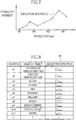
- An example of the reflection spectra S obtained by the reflection spectrum calculator 80 may be plotted on a line graph as shown in Fig.7 , wherein the spectral intensities determined by the pixel levels are plotted at the center wavelengths of the respective wavelength bands for acquiring vascular information, at 405 nm, 445 nm and 473 nm in this example, and at the center wavelengths of the respective bands B1 to B7, i.e. at 425 nm, 475 nm, 525 nm, 575 nm, 625 nm, 675 nm and 725 nm.
- the reflection spectrum calculator 80 outputs the data of the obtained reflection spectra S to the multi-regression analyzer 81.
- the reflection spectrum calculator 80 may calculate the reflection spectra S with respect to those parts of the image which correspond to blood vessels.
- the parts corresponding to blood vessels may for example be identified by the difference in luminance between pixels because the blood vessels have different luminance values from other parts.
- the reflection spectrum calculator 80 may also calculate the reflection spectra S with respect to a region of interest (ROI) that the operator can designate within the acquired image by operating the operating section 48. It is also possible to calculate the reflection spectra S for each individual subdivided segment of the imaging area of the CCD 35. The same applies to the following stages, including the multi-regression analyzer 81 and the vascular information acquiring section 84.
- ROI region of interest
- the multi-regression analyzer 81 makes multi-regression analysis using the reflection spectra S as a response variable, and absorption spectra a1, a2 ... of blood and bile as explanatory variables. Since the reflection spectra S cover the whole wavelength range of the light reflected from the target site, ranging from 400 nm to 750 nm, it can be regarded as a sum of absorption spectra of multiple objects existing in the target site and absorbing light in the wavelength range of 400 nm to 750 nm, as being multiplied by appropriate coefficients.
- these weighting coefficients are determined through the least-squares method or the like. More specifically, these weighting coefficients are determined by solving a system of equations, in which a root-mean-square difference between a reflection spectrum S obtained by the reflection spectrum calculator 80 (an actual measurement value) and a reflection spectrum S obtained through the regression formula (a calculus value) is set to zero by differentiation with respect to the weighting coefficients, so as to minimize the root-mean-square difference between the actual measurement value and the calculus value.
- the multi-regression analyzer 81 outputs data of the regression formula, including the determined weighting coefficients, to the evaluating and deciding section 82.
- the absorption spectra have inverted intensities to the reflection spectra, and hence they represent substantially the same optical property. Therefore the above formula, by which the absorption spectra of the respective objects are multiplied by the weighting coefficients and summed up, may stand for the regression formula of the reflection spectra S.
- the absorption spectra a1, a2 ... of those objects which potentially exist in the target site may be previously memorized in the ROM 46, in the form of an absorption spectrum table 90 as shown in Fig.8 .
- the absorption spectrum table 90 stores data of absorption spectra of individual objects, each in association with the substance name and its identifier a1, a2 ... used in the regression formula.
- the absorption spectra may be linear data plotted on a line graph in the same manner as the reflection spectra S shown in Fig.7 .
- the identifiers a1 and a2 respectively represent the absorption spectra of oxygen hemoglobin (HbO) and reduced hemoglobin (Hb), whereas a3 represents the absorption spectra of blood, a4 blood plasma, and a5 bile.
- the identifiers a9, a10 and a11 represent the respective absorption spectra of indigocarmine, crystal violet and iodine, which may be administered into the test subject for staining the target site.
- the absorption spectra data may be nonlinear data, or data of a combination of absorption spectra of various objects.
- the absorption spectra data may also include DC components.
- the absorption spectrum table 90 may be recorded on a removable medium instead of the ROM 46, so that it may be read out from the removable medium into the image processing circuit 49.
- the evaluating and deciding section 82 evaluates the degree of contribution of irrelevant objects, or objects of no interest, to the reflection spectra S, and decides by the evaluation result whether the eliminating section 83 should eliminate spectral components originated from the objects of no interest from the reflection spectra S.
- the objects of no interest include such substances that may hinder the acquisition of the vascular information, while blood or its components like oxygen hemoglobin and reduced hemoglobin are relevant objects necessary for acquiring vascular information.
- secretions such as bile and mucin, and staining materials such as indigocarmine are recited as the objects of no interest.
- the evaluating and deciding section 82 compares the weighting coefficient assigned to the absorption spectra of irrelevant objects in the regression formula, e.g. the weighting coefficient k5 when bile is the irrelevant object, with a predetermined threshold TH. If the compared weighting coefficient is greater than the threshold TH, the evaluating and deciding section 82 evaluates that the contribution degree of the irrelevant object to the reflection spectra S is high, and decides that spectral components originated from the irrelevant objects should be eliminated from the reflection spectra S in the eliminating section 83.
- the evaluating and deciding section 82 evaluates that the contribution degree of the irrelevant object is so low that this irrelevant object does not affect the acquisition of the vascular information, and decides not to eliminate the spectral components of the irrelevant object from the reflection spectra S. Then the evaluating and deciding section 82 outputs the decision to the eliminating section 83.
- the evaluating and deciding section 82 may make the evaluation and decision in other ways. For example, the evaluation and decision may be made depending upon the result of comparison of the difference or ratio between the weighting coefficient for the irrelevant object and the weighting coefficient for the relevant object with a threshold. If the difference or ratio between the compared weighting coefficients is greater than the threshold, the evaluating and deciding section 82 decides to eliminate the spectral components of the irrelevant object. Alternatively, a value calculated from multiple weighting coefficients, e.g. a weighted average of the respective weighting coefficients may be used as an index for the evaluation and decision.
- the evaluation and decision may also be made on the basis of statistics for judging significance of the regression formula obtained by the multi-regression analysis or the weighting coefficients of this formula.
- the applicable statistics may include p-value, F-value and a degree-of-freedom adjusted coefficient of determination (contribution rate or degree of influence).
- the p-value indicates reliability of the weighting coefficients such that the weighting coefficients determined by the multi-regression analysis may be more reliable and true the closer the p-value to zero.
- the F-value is served as an index for statistical hypothesis testing as to whether to withdraw a null hypothesis that the regression formula is not useful for calculating the reflection spectra S, and adopt an alternative hypothesis that the regression formula is useful for calculating the reflection spectra S.
- the degree-of-freedom adjusted coefficient of determination is an index indicating how much degrees the absorption spectra a1, a2 ... in total, explanatory variables, can forecast the reflection spectra S as an objective variable.
- the evaluating and deciding section 82 may judge the significance of the regression formula and the significance of the weighting coefficient for the irrelevant object. Then, the evaluating and deciding section 82 may decide to eliminate the spectral components of irrelevant objects when the regression formula and the weighting coefficient for the irrelevant object are judged to be significant and, at the same time, the weighting coefficient for the irrelevant object (or the difference of the weighting coefficient for the irrelevant object from the weighting coefficient for the relevant object, or the ratio between them) is greater than the predetermined threshold TH. Alternatively, the decision may be made upon the significance judgment alone, without making the comparison with threshold TH.
- the eliminating section 83 eliminates the spectral components originated from irrelevant objects (the fractions that the irrelevant objects contribute to or have influence on the reflection spectra S) from the reflection spectra S, for example, by subtracting those data values which are produced by multiplying the absorption spectra of the relevant objects by the weighting coefficients from the actual measurement values of the reflection spectra S. Then the eliminating section 83 outputs the reflection spectra S' from which the spectral components of irrelevant objects are eliminated, hereinafter referred to as the subsequent reflection spectra S', to the vascular information acquiring section 84.
- the eliminating section 83 is not activated, and merely the reflection spectra S obtained by the reflection spectrum calculator 80 is transferred to the vascular information acquiring section 84.
- the vascular information acquiring section 84 acquires information about blood vessels in the target site on the basis of the reflection spectra S and/or the subsequent reflection spectra S' : using both reflection spectra S and S' when decided to eliminate the components of irrelevant objects, or using only the reflection spectra S when decided not to eliminate.
- the vascular information may include oxygen saturation of blood hemoglobin, images of superficial, intermediate and deep blood vessels, and depths of the vessels from the surface of the target site.
- the vascular information acquiring section 84 calculates intensity ratios between the intensities of the reflection spectra S or the subsequent reflection spectra S' , for example, at the wavelengths of 405 nm, 445 nm and 473 nm, and derives oxygen saturation values corresponding to calculated intensity ratios from a predetermined relation between the intensity ratio and the oxygen saturation.
- the vascular information acquiring section 84 may also acquire the vessel depth information from the intensities of the reflection spectra S or the subsequent reflection spectra S', for example, at the wavelengths of 450 nm, 550 nm and 780 nm. That is, if the spectral intensity at 450 nm is higher than others, it may represent superficial blood vessels, whereas high intensity at 550 nm may represent intermediate blood vessels, and high intensity at 780 nm may represent deep blood vessels.
- the eliminating section 83 takes a reversed procedure to that taken by the reflection spectrum calculator 80 to obtain the reflection spectra S from the pixel levels: multiplying the absorption spectra of irrelevant objects with weighting coefficients, converting the multiplication products to pixel levels, and subtracting these pixel levels from the image data.
- the oxygen saturation or the vessel depth information may be obtained from data of pixel-level-subtracted images. Specifically, the oxygen saturation or the vessel depth may be calculated from luminance ratios between those pixel-level-subtracted images which are obtained under the narrowband rays of above-mentioned wavelengths. The oxygen saturation or the vessel depth may also be calculated from the amounts of blurs in these images.
- the vascular information acquired by the vascular information acquiring section 84 is overlaid on a composite image that may consist of multiple frames of image data G or the like, to be displayed as a vascular information image on the monitor 19.
- the display control circuit 50 may control the monitor 19 to display the vascular information image obtained based on the reflection spectra S and the vascular information image obtained based on the subsequent reflection spectra S' one by one.
- the vascular information image based on the reflection spectra S and the vascular information image based on the subsequent reflection spectra S' may also be displayed side by side, as shown in Fig.9A .
- the way of displaying these vascular information images may be switched over in response to a manual operation or automatically at regular time intervals.
- these images may be displayed in an overlaid fashion. This facilitates comparison between these images, and hence the diagnoses. Moreover, the operator can visually confirm the function of the eliminating section 83, and feel more assured. If the evaluating and deciding section 82 decides that there is no need for the elimination, the monitor 19 will display only the vascular information image obtained based on the reflection spectra S without the elimination process.
- the vascular information may be displayed as numerical values or text.
- the oxygen saturation may be indicated as numerical values (%)
- the vessel depth may be indicated as annotations such as "superficial", "intermediate”, etc. to the corresponding vessels.
- the vascular information may be expressed as color maps.
- the vessels of low oxygen saturation may be displayed in cyan
- the vessels of middle oxygen saturation may be displayed in magenta
- the vessels of high oxygen saturation may be displayed in yellow.
- the superficial vessels may be displayed in blue, the intermediate vessels green, and the deep vessels red.
- literal information 95 may be displayed in a way as shown for example in Fig.9B , about whether any irrelevant objects are found or not, as well as whether the irrelevant objects have influence on the acquisition of the vascular information. Judgment as to whether any irrelevant objects exist or not and whether the irrelevant objects have any influence on the vascular information may be made with reference to the decision by the evaluating and deciding section 82.
- the evaluating and deciding section 82 evaluates that the weighting coefficient of any irrelevant object is significant, and the weighting coefficient of the irrelevant object (or the difference thereof from the weighting coefficient of the relevant object, or the ratio thereof to the weighting coefficient of the relevant object) is above the threshold TH, the displayed literal information notifies that the irrelevant object exists and it has influence on the vascular information. Even if the weighting coefficient has significance, if it is below the threshold TH, the literal information notifies that the irrelevant object exists but it has no influence on the vascular information.
- the weighting coefficients of the irrelevant objects may be directly displayed. It is also possible to change the level of display according to the magnitude of the weighting coefficients. For example, the literal information 95 may be twinkled if any of the weighting coefficients is largely above the threshold TH.
- the operator To inspect the inside of the test subject by the endoscope 10, the operator connects the endoscope 10 to the respective units 11 and 12, and turns on the powers of the respective units 11 and 12. Then the operator operates the operating section 48 to input information about the test subject and other data before inputting a start command.
- the operator After inputting the start command, the operator introduces the probing portion 13 into the test subject while illuminating the inside of the subject body with the illumination light from the light source unit 12, and watching the images of internal organs of the test subject on the monitor 19, the inspection images captured by the CCD 35.
- the image signal output from the CCD 35 is processed through the respective components of the AFE 38, and then fed to the image processing circuit 49 of the processor unit 11.
- the image processing circuit 49 the input image signal is processed in various ways to produce an image.
- the image processed in the image processing circuit 49 is fed to the display control circuit 50.
- the display control circuit 50 executes various kinds of display control processing according the graphic data from the CPU 45. Thus the inspection images are displayed on the monitor 19.
- the electronic endoscope system 2 may be switchable between the ordinary inspection mode and the special inspection mode according to the inspection object. While the probing portion 13 is being introduced into the test subject body, the ordinary inspection mode should be selected to project the white illumination light in order to inspect the images in a wide field of view. When a lesion is found to be examined in detail, the special inspection mode is selected to project a narrowband ray of a wavelength suitable for the inspection of that lesion. The operator can operate the release button to capture still images, or insert any necessary surgical tool through the tool channel of the endoscope 10, so that the operator can inject staining material into the lesion, cut it off, or apply medication to it.
- the ordinary inspection light source 60 is turned on under the control of the CPU 45, to project the white light from the light projection window 31 toward a target site.
- the special inspection light source 61 is turned on.
- the white light from the special inspection light source 61 is incident on the wavelength tunable element 68, so that narrowband rays of a limited wavelength band are selectively output from the wavelength tunable element 68.
- the narrowband ray from the wavelength tunable element 68 is conducted through the light guide 36 to the distal end 17 of the endoscope 10, to be projected from the light projection window 31 toward the target site.
- a reflection spectra acquiring process is executed, as shown in step 10 (S10) in Fig. 10 .
- the wavelength tunable element 68 is driven to project the narrowband rays for acquiring vascular information and the narrowband rays of the bands B1 to B7, the seven 50 nm bands subdividing the wavelength range of 400 nm to 750 nm, toward the target site, turn by turn at the same intervals as the charge accumulation in the CCD 35.
- an image of the target site is captured by the CCD 35 each time the narrowband ray of one of these wavelength bands is projected.
- multiple frames of image data G are obtained.
- the reflection spectrum calculator 80 detects reflection spectra S.
- the multi-regression analyzer 81 refers to the absorption spectrum table 90 to determine the regression formula representing the reflection spectra S using the respective absorption spectra "an” of the objects and the weighting coefficients "kn" and "m” thereof (S11).
- the evaluating and deciding section 82 compares the weighting coefficients of the irrelevant objects in the regression formula with the threshold TH, to decide whether the spectral components of the irrelevant objects should be eliminated from the reflection spectra S for use in acquiring the vascular information (S12).
- the eliminating section 83 eliminates spectral components of the irrelevant objects from the reflection spectra S (S14) .
- the result is "not to eliminate” ("NO” in S13)
- the elimination of the spectral components of the irrelevant objects is not executed.
- the vascular information acquiring section 84 acquires the vascular information on the basis of the reflection spectra S or the subsequent reflection spectra S' (S15).
- the acquired vascular information is processed in the display control circuit 50, for example, for false-coloring.
- the processed vascular information is displayed on the monitor 19 (S16). More specifically, when the result of judgment by the evaluating and deciding section 82 is "to eliminate", a vascular information image based on the reflection spectra S and a vascular information image based on the subsequent reflection spectra S' are displayed on the monitor 19, preferably in parallel to each other.
- the vascular information is acquired after eliminating the spectral components of irrelevant objects from the reflection spectra, the vascular information becomes more reliable, so is the diagnosis based on the vascular information. Moreover, since it is determined whether the spectral components originated from the irrelevant objects have any influence on the vascular information, in order to skip the elimination process if the irrelevant objects have no remarkable influence on the acquisition of vascular information, the resource of the image processing circuit 49 would not be wasted by making the elimination process unnecessarily.
- the weighting coefficients can be utilized for the following evaluation, decision and elimination processes.
- the wavelength tunable element 68 is disposed on the output of the special inspection light source 61.
- the wavelength tunable element 68 may be disposed on the output of the light guide 36.
- the wavelength tunable element 68 may also be disposed in the objective lens system for capturing images of the target site.
- the wavelength tunable element 68 may be disposed behind an inspection window 30, as is shown in an endoscope 100 of Fig.11 , or may also be placed on the imaging surface of the CCD 35.
- the light source unit 12 shall have only an ordinary inspection light source, and the reflection spectra S will be obtained by changing the wavelength band of the incident light on the CCD 35 through the wavelength tunable element 68 while the white light is being projected from the ordinary inspection light source.
- absorption spectra of various objects have been previously experimentally obtained.
- the respective absorption spectra of various objects may be measured as actual data during the inspection.
- the irrelevant objects are physically eliminated from the target site during the special inspection mode, in order to obtain image data G from the target site before and immediately after the physical elimination of irrelevant objects.
- the reflection spectrum calculator 80 calculates the reflection spectra S and S" from the image data G obtained before and immediately after the elimination of irrelevant objects.
- the physical elimination of irrelevant objects may be done by blowing air or ejecting water into the body cavity of the test subject through the insufflating and watering nozzle 33 of the endoscope 10 or a specific tool inserted through the tool channel of the endoscope 10.
- Irrelevant objects may also be eliminated by suction into a catheter connected to an aspirator.
- Absorption spectra "an” of irrelevant objects will be obtained by subtracting the reflection spectra S" obtained after the elimination process from the reflection spectra S obtained before the elimination process. Therefore, in this embodiment, the absorption spectrum table 90 has only to memorize absorption spectra of relevant objects.
- the reason why the reflection spectra S" is obtained immediately after the physical elimination of the irrelevant objects is because some kinds of irrelevant objects like secretions, including bile, will come back to the same condition in a certain time after the physical elimination thereof.
- the difference between reflection spectra obtained before administration of the staining material i.e. in a condition where the staining material does not exist in the target site
- reflection spectra obtained after the administration of the staining material i.e. in a condition where the staining material exists in the target site.
- absorption spectra of various objects may be representative examples, which do not take account of such differences in absorption spectra that may be resulted from individual variability of the test subjects or patients.
- absorption spectra of objects inside the patient are obtained as actually measured values in a real time fashion from differences between reflection spectra acquired before eliminating irrelevant objects and reflection spectra acquired after eliminating irrelevant objects, the differences between individual patients will be accommodated so that the subsequent vascular information will be more reliable .
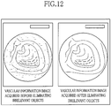
- the respective vascular information images may be displayed in parallel on the monitor 19, as shown in Fig.12 , or may also be displayed in an overlaid fashion (or in a time-sequential fashion if there is a time lag between the two conditions) . It may also be possible to execute the elimination of spectral components originated from irrelevant objects in the eliminating section 83 in addition to the physical elimination of irrelevant objects, so as to display four vascular information images of the same target site: vascular information images produced before and after the spectral components of irrelevant objects being eliminated, and vascular information images acquired before and after irrelevant objects being eliminated, in parallel to each other or in a overlaid fashion. With reference to these images, the operator can see if the eliminating section 83 works well.
- the calculation of reflection spectra may be omitted, and the vascular information may be obtained based on the pixel levels using differences or ratios between weighting coefficients of irrelevant objects and weighting coefficients of relevant objects.
- the real-time measurement of absorption spectra of the objects may be started in response to an operation on the 18 of the endoscope 10 or on an operational button of the specific tool for the physical elimination of irrelevant objects. It may also be preferable to make a database from absorption spectra of various objects, which have been obtained in the past.
- discrimination between relevant objects and irrelevant objects may be selectable by the operator.
- a sorting list 105 may be displayed on the monitor 19, so that the operator can sort various substances into concerned, unconcerned and excluded objects by marking corresponding check boxes using the operating section 48.
- the excluded objects items for absorption spectra of these substances are excluded from the regression formula, so that the multi-regression analysis of the excluded objects will not be executed.
- the threshold TH for use in the evaluation and decision process may be adjustable by the operator using the operating section 48, or may also be automatically adjustable by the CPU 45.
- the number of narrow wavelength bands in which the illumination light is time-sequentially projected for acquiring the reflection spectra S is not to be limited to the above embodiment but may be other than seven. Also the coverage of the illumination light is not to be limited to the range of 400 nm to 750 nm. The more the number of wavelength bands, the higher the resolution in calculating the reflection spectra S becomes, but it will take more time to acquire the reflection spectra S. Therefore, the number of wavelength bands should be determined appropriately so as to get an optimum balance between the resolution in calculating the reflection spectra S and the data acquisition time. Note that the narrowband rays for acquiring vascular information may not necessarily be projected if the resolution in calculating the reflection spectra S is sufficient.
- the reflection spectra S may be obtained using other devices than the wavelength tunable element 68 as used in the above embodiment.
- an optical image received from the target site may be spectrally divided through a color separation prism into multiple beams of different wavelength bands, to be captured by CCDs mounted on the respective outlet surfaces of the color separation prism.
- a spectrum analyzer that utilizes a digital light processor or DLP (a trade name), by OneLight Corporation (URL: http://www.onelightcorp.com/products/index.html), which adopts a xenon lamp as a light source and modifies the wavelength band of the light using an array of reflection mirrors in order to obtain reflection spectra of substances.
- oxygen saturation and vessel depth are detected as information about the target site using the narrowband rays.
- the present invention should not be limited to the above embodiments.
- the present disclosure is applicable to those cases where a fluorescent material is injected into body tissues and then light for exciting the fluorescent material is projected toward a target site to inspect fluorescence from the target site, as well as where intrinsic fluorescence of body tissues is inspected.
- the imaging device is not limited to the above-described CCD image sensor, but may be a CMOS image sensor.
- the endoscope system of the present invention may use a monochrome CCD.
- a rotary filter is placed on the output side of an ordinary inspection light source or white light source.
- the rotary filter has RGB filters arranged around the circumferential direction, to transmit red, green and blue ray components of the white light according to the rotational position of the rotary filter.
- the monochrome CCD captures image data of a corresponding color frame at each projection of one color light. Then a full-color image is produced from the three color image frames.
- the present disclosure is applicable not only to an electronic endoscope system, but also to other kinds of endoscope systems, including those using an ultrasonic endoscope where an imaging device and an ultrasonic transducer are mounted in a scope distal end.
- the application field of the present disclosure is not limited to the medical field.
- the present disclosure may be applied to a system used in the industrial field. Accordingly, the above-mentioned objects of interest, or relevant objects, are not limited to blood or its components, and, unlike the invention, the information to be acquired by an endoscope system of the present disclosure is not limited to vascular or biological information.
Landscapes
- Health & Medical Sciences (AREA)
- Life Sciences & Earth Sciences (AREA)
- Physics & Mathematics (AREA)
- Surgery (AREA)
- Engineering & Computer Science (AREA)
- Spectroscopy & Molecular Physics (AREA)
- General Health & Medical Sciences (AREA)
- Pathology (AREA)
- Biomedical Technology (AREA)
- Heart & Thoracic Surgery (AREA)
- Medical Informatics (AREA)
- Molecular Biology (AREA)
- Biophysics (AREA)
- Animal Behavior & Ethology (AREA)
- Public Health (AREA)
- Veterinary Medicine (AREA)
- Optics & Photonics (AREA)
- Nuclear Medicine, Radiotherapy & Molecular Imaging (AREA)
- Radiology & Medical Imaging (AREA)
- General Physics & Mathematics (AREA)
- Multimedia (AREA)
- Astronomy & Astrophysics (AREA)
- Signal Processing (AREA)
- Endoscopes (AREA)
- Investigating Or Analysing Materials By Optical Means (AREA)
- Instruments For Viewing The Inside Of Hollow Bodies (AREA)
- Closed-Circuit Television Systems (AREA)
- Measurement Of The Respiration, Hearing Ability, Form, And Blood Characteristics Of Living Organisms (AREA)
Claims (7)
- Medizinisches Endoskopsystem mit einer Lichtprojektionseinrichtung (12) zum Projizieren von Licht in verschiedenen schmalbandigen Wellenlängenbändern auf einen Zielort eines zu inspizierenden Testsubjekts und mit einer Bildgebungseinrichtung (35) zum Aufnehmen von Licht, das von dem Zielort reflektiert oder von diesem emittiert wurde, um ein Bildsignal auszugeben, umfassend:eine Reflexionsspektrum-Gewinnungseinrichtung (80, 34, 35), ausgebildet zum Gewinnen erster Reflektionsspektren (S) auf der Grundlage von Bilddaten (G) einer Anzahl von Einzelbildern, die sequentiell von der Bildgebungseinrichtung aus von der Lichtprojektionseinrichtung projizierten und von dem Zielort reflektiertem Licht in den unterschiedlichen schmalbandigen Wellenlängenbändern aufgenommen wurden;eine Speichereinrichtung (46) zum Vorab-Speichern von Absorptionsspektra relevanter Objekte und irrelevanter Objekte, wobei relevante Objekte Substanzen sind, die notwendig sind zum Erfassen von Vaskularinformation wie beispielsweise Blut oder dessen Bestandteile wie sauerstoffreiches Hämoglobin und sauerstoffarmes Hämoglobin, und die irrelevanten Objekte Substanzen sind, die möglicherweise das Erfassen von Vaskularinformation behindern, so zum Beispiel Sekrete von dem Testsubjekt oder auf das Testsubjekt gelangtes Verunreinigungsmaterial, wobei die vorab gespeicherten Absorptionsspektra mindestens ein Absorptionsspektrum für jede Substanz enthalten;eine Berechnungseinrichtung (81) zum Berechnen von Spektralkomponenten, die ihren Ursprung in irrelevanten Objekten in den ersten Reflektionsspektra haben, erhalten durch Vergleich der ersten Reflektionsspektra mit den Absorpionspektra von mindestens einem der relevanten Objekte und der irrelevanten Objekte, die vorab in der Speichereinrichtung abgespeichert wurden;eine Auswertungs- und Entscheidungseinrichtung (82), ausgebildet zum Auswerten der Einflussstärke der individuellen irrelevanten Objekte auf die ersten Reflexionsspektra auf der Grundlage der Spektralkomponenten, die ihren Ursprung in den irrelevanten Objekten innerhalb der ersten Reflexionsspektra haben, und ausgebildet zum Entscheiden anhand der Einflussstärke, ob die Spektralkomponente der individuellen irrelevanten Objekte aus den ersten Reflexionsspektra zu eliminieren sind oder nicht;und eine Eleminiereinrichtung (83), ausgebildet, um, wenn so von der Auswertungs- und Entscheidungseinrichtung entschieden wird, die Spektralkomponenten der irrelevanten Objekte, berechnet durch die Berechnungseinrichtung (81), aus den ersten Reflextionsspektra zu eliminieren, um so zweite Reflektionsspektra (S') zu gewinnen;eine Vaskularinformations-Erfassungseinrichtung (84), ausgebildet zum Erfassen von Information über Blutgefäße an dem Zielort als die Vaskularinformation auf der Grundlage der ersten Reflexionsspektra (S), aus denen die Spektralkomponenten der irrelevanten Objekte nicht eleminiert werden, und, falls von der Auswertungs- und Entscheidungseinrichtung so entschieden, zum Eliminieren der Komponenten individueller irrelevanter Objekte, ebenfalls auf der Grundlage der zweiten Reflektionsspektra (S'), aus denen die Spektralkomponenten der individuellen irrelevanten Objekte eliminiert wurden; undeine Anzeigeeinrichtung (19, 50), ausgebildet zum graphischen Anzeigen der Vaskularinformation, wobei die Anzeigeeinrichtung (19, 50) dazu ausgebildet ist, gleichzeitig Anzeigebilder anzuzeigen, welche die Vaskularinformation in einem Zustand darstellen, bevor der Einfluss der irrelevanten Objekte eliminiert wurde, und in einem Zustand, nachdem der Einfluss der irrelevanten Objekte eliminiert wurde.
- Endoskopsystem nach Anspruch 1, bei dem die Berechnungseinrichtung (81) dazu ausgebildet ist, die Spektralkomponenten zu berechnen, die aus den irrelevanten Objekten innerhalb der ersten Reflektionsspektra stammen, mittels einer Multi-Regressionsanalyse unter Verwendung der ersten Reflexionsspektra als Antwortvariable und der zuvor abgespeicherten Absorptionsspektra der relevanten und irrelevanten Objekte als Erklärungsvariable, wozu die zuvor gespeicherten Absorptionsspektra der irrelevanten Objekte multipliziert werden mit den zugehörigen Wichtungskoeffizienten, die für jedes Absorptionsspektrum durch die Multiregressionsanalyse bestimmt werden.
- Endoskopsystem nach Anspruch 1, ferner enthaltend in einem Endoskop (10) vorgesehene Aufblas- und Wässerungsfunktion (30).
- Endoskopsystem nach Anspruch 2, bei dem
die Auswertungs- und Entscheidungseinrichtung (82) dafür ausgebildet ist, die Stärke des Einflusses der irrelevanten Objekte auf die ersten Reflexionsspektra auszuwerten, indem entweder die Richtungskoeffizienten verwendet werden, die für die Absorptionsspektra der irrelevanten Objekte durch die Multiregressionsanalyse bestimmt werden, oder unter Verwendung eines statistischen Werts zum Beurteilen der Signifikanz der Multiregressionsanalyse, oder unter Verwendung von beidem. - Endoskopsystem nach einem der vorhergehenden Ansprüche, bei dem die Anzeigeeinrichtung dazu ausgebildet ist, Information darüber anzuzeigen, ob es irgendwelche irrelevanten Objekte an dem Zielort gibt, und/oder die Stärke des Einflusses irrelevanter Objekte auf die ersten Reflexionsspektra anzuzeigen.
- Endoskopsystem nach einem der Ansprüche 1 bis 5, bei dem die Lichtprojektionseinrichtung (12) der Reflexionsspektrum-Gewinnungseinrichtung (80, 34, 35) ein wellenlängen-abstimmbares Element (68) enthält, welches im Wellenlängenband von Transmissionsstrahlen abstimmbar ist.
- Endoskopsystem nach einem der Ansprüche 1 bis 6, bei dem die Reflexionsspektrum-Gewinnungseinrichtung die Bildgebungseinrichtung (35), ein Objektivsystem (34) zum Bilden eines optischen Bilds des Zielorts auf der Bildgebungseinrichtung, und einem Reflextionsspektrumrechner (80) zum Berechnen der Reflektionsspektra basierend auf dem von der Bildgebungseinrichtung ausgegebenen Bildsignal enthält, wobei das Objektivsystem und die Bildgebungseinrichtung sich an einem distalen Ende (17) eines Sondenabschnitts (13) eine Endoskops (10) befinden.
Applications Claiming Priority (1)
| Application Number | Priority Date | Filing Date | Title |
|---|---|---|---|
| JP2011003110A JP5466182B2 (ja) | 2011-01-11 | 2011-01-11 | 内視鏡システムおよび内視鏡システムの作動方法 |
Publications (3)
| Publication Number | Publication Date |
|---|---|
| EP2474853A2 EP2474853A2 (de) | 2012-07-11 |
| EP2474853A3 EP2474853A3 (de) | 2013-01-23 |
| EP2474853B1 true EP2474853B1 (de) | 2019-01-16 |
Family
ID=44862699
Family Applications (1)
| Application Number | Title | Priority Date | Filing Date |
|---|---|---|---|
| EP11186707.3A Active EP2474853B1 (de) | 2011-01-11 | 2011-10-26 | Elektronisches Endoskopsystem |
Country Status (3)
| Country | Link |
|---|---|
| US (1) | US9113787B2 (de) |
| EP (1) | EP2474853B1 (de) |
| JP (1) | JP5466182B2 (de) |
Families Citing this family (25)
| Publication number | Priority date | Publication date | Assignee | Title |
|---|---|---|---|---|
| US9553034B1 (en) * | 2012-03-27 | 2017-01-24 | Kla-Tencor Corporation | Combined semiconductor metrology system |
| JP2013240401A (ja) * | 2012-05-18 | 2013-12-05 | Hoya Corp | 電子内視鏡装置 |
| JP6077340B2 (ja) * | 2013-03-06 | 2017-02-08 | 富士フイルム株式会社 | 画像処理装置及び内視鏡システムの作動方法 |
| JP6039639B2 (ja) * | 2014-02-27 | 2016-12-07 | 富士フイルム株式会社 | 内視鏡システム、内視鏡システム用プロセッサ装置、内視鏡システムの作動方法、及び内視鏡システム用プロセッサ装置の作動方法 |
| JP6010571B2 (ja) * | 2014-02-27 | 2016-10-19 | 富士フイルム株式会社 | 内視鏡システム、内視鏡システム用プロセッサ装置、内視鏡システムの作動方法、内視鏡システム用プロセッサ装置の作動方法 |
| EP3127469B1 (de) * | 2014-03-31 | 2019-09-04 | Fujifilm Corporation | Endoskopsystem |
| JP6085649B2 (ja) * | 2014-08-29 | 2017-02-22 | 富士フイルム株式会社 | 内視鏡用光源装置及び内視鏡システム |
| JP6085648B2 (ja) * | 2014-08-29 | 2017-02-22 | 富士フイルム株式会社 | 内視鏡用光源装置及び内視鏡システム |
| CN107306491B (zh) * | 2015-01-23 | 2020-03-03 | 奥林巴斯株式会社 | 图像处理装置、图像处理方法以及记录介质 |
| WO2016158276A1 (ja) | 2015-04-02 | 2016-10-06 | 富士フイルム株式会社 | プロセッサ装置及びその作動方法並びに内視鏡システム及びその作動方法 |
| WO2017010157A1 (ja) * | 2015-07-15 | 2017-01-19 | ソニー株式会社 | 医療用観察装置及び医療用観察方法 |
| JP6596502B2 (ja) * | 2015-10-08 | 2019-10-23 | オリンパス株式会社 | 内視鏡装置 |
| JPWO2017085793A1 (ja) * | 2015-11-17 | 2018-09-13 | オリンパス株式会社 | 内視鏡システム、画像処理装置、画像処理方法およびプログラム |
| JP6884356B2 (ja) * | 2016-03-31 | 2021-06-09 | 国立研究開発法人産業技術総合研究所 | 観察装置、観察システム、データ処理装置及びプログラム |
| JPWO2017216883A1 (ja) | 2016-06-14 | 2019-04-04 | オリンパス株式会社 | 内視鏡装置 |
| WO2017216878A1 (ja) * | 2016-06-14 | 2017-12-21 | オリンパス株式会社 | 内視鏡装置 |
| JP2017000836A (ja) * | 2016-09-27 | 2017-01-05 | Hoya株式会社 | 電子内視鏡装置 |
| WO2018073784A1 (en) | 2016-10-20 | 2018-04-26 | Optina Diagnostics, Inc. | Method and system for detecting an anomaly within a biological tissue |
| WO2018105020A1 (ja) | 2016-12-05 | 2018-06-14 | オリンパス株式会社 | 内視鏡装置 |
| DE112018001744T5 (de) * | 2017-03-29 | 2019-12-19 | Sony Corporation | Medizinische Bildgebungsvorrichtung und Endoskop |
| JP6858672B2 (ja) * | 2017-08-29 | 2021-04-14 | 富士フイルム株式会社 | 医療画像処理システム及び内視鏡システム |
| CN109998681B (zh) * | 2019-03-16 | 2022-02-01 | 哈尔滨理工大学 | 一种区分镜面反射区域和血管的内腔图像预处理方法 |
| JP7346357B2 (ja) * | 2020-06-01 | 2023-09-19 | 富士フイルム株式会社 | 内視鏡システム |
| US20240424267A1 (en) * | 2023-06-23 | 2024-12-26 | Olympus Medical Systems Corp. | Method for treating rhinosinusitis |
| WO2025187496A1 (ja) * | 2024-03-05 | 2025-09-12 | 富士フイルム株式会社 | 内視鏡システム及びその作動方法 |
Family Cites Families (19)
| Publication number | Priority date | Publication date | Assignee | Title |
|---|---|---|---|---|
| DE69231614T2 (de) * | 1991-02-26 | 2001-05-03 | Massachusetts Institute Of Technology, Cambridge | Molekularspektroskopieverfahren und -einrichtungen zur gewebediagnose |
| US6939293B2 (en) * | 2003-08-07 | 2005-09-06 | Chris N. Conteas | Gastrointestinal lavage system |
| US7532320B2 (en) * | 2004-06-30 | 2009-05-12 | Chemimage Corporation | Multimodal method for identifying hazardous agents |
| US7479106B2 (en) * | 2004-09-30 | 2009-01-20 | Boston Scientific Scimed, Inc. | Automated control of irrigation and aspiration in a single-use endoscope |
| JP4350652B2 (ja) * | 2005-01-07 | 2009-10-21 | オリンパスメディカルシステムズ株式会社 | 内視鏡用挿入部及び内視鏡 |
| JP5114003B2 (ja) * | 2005-11-04 | 2013-01-09 | オリンパス株式会社 | 蛍光内視鏡装置 |
| JP4739817B2 (ja) | 2005-05-30 | 2011-08-03 | 俊徳 加藤 | ヘモグロビン観察装置及びヘモグロビン観察方法 |
| JP4954573B2 (ja) * | 2006-02-28 | 2012-06-20 | オリンパス株式会社 | 内視鏡システム |
| JP4391998B2 (ja) * | 2006-03-07 | 2009-12-24 | オリンパス株式会社 | 内視鏡装置 |
| BRPI0710154A2 (pt) | 2006-04-12 | 2011-08-02 | Olympus Medical Systems Corp | aparelho endoscópico |
| WO2008144760A1 (en) * | 2007-05-21 | 2008-11-27 | Board Of Regents, The University Of Texas System | Optical methods to intraoperatively detect positive prostate and kidney cancer margins |
| EP2194834A2 (de) * | 2007-09-24 | 2010-06-16 | Jetprep Ltd. | Virtuelle kanal-aktivierungsvorrichtung zur verwendung bei der einführung eines endoskopischen instruments und zur renigung von körperhöhlen |
| JP5074256B2 (ja) * | 2008-03-24 | 2012-11-14 | オリンパス株式会社 | 蛍光観察装置 |
| JP2009240354A (ja) * | 2008-03-28 | 2009-10-22 | Fujinon Corp | 電子内視鏡装置 |
| JP5534288B2 (ja) * | 2008-04-02 | 2014-06-25 | 富士フイルム株式会社 | 信号処理装置、信号処理装置の作動方法、およびプログラム |
| JP5389380B2 (ja) * | 2008-05-28 | 2014-01-15 | オリンパス株式会社 | 信号処理システム及び信号処理プログラム |
| JP5191329B2 (ja) * | 2008-09-19 | 2013-05-08 | 富士フイルム株式会社 | 画像取得装置 |
| EP2359745A1 (de) * | 2010-02-12 | 2011-08-24 | Helmholtz Zentrum München Deutsches Forschungszentrum für Gesundheit und Umwelt (GmbH) | Verfahren und Vorrichtung zur multispektralen photonischen Bildgebung |
| US8645082B2 (en) * | 2010-09-13 | 2014-02-04 | Mks Instruments, Inc. | Monitoring, detecting and quantifying chemical compounds in a sample |
-
2011
- 2011-01-11 JP JP2011003110A patent/JP5466182B2/ja active Active
- 2011-10-26 EP EP11186707.3A patent/EP2474853B1/de active Active
- 2011-10-27 US US13/283,396 patent/US9113787B2/en active Active
Non-Patent Citations (1)
| Title |
|---|
| None * |
Also Published As
| Publication number | Publication date |
|---|---|
| JP2012143349A (ja) | 2012-08-02 |
| EP2474853A2 (de) | 2012-07-11 |
| US20120176486A1 (en) | 2012-07-12 |
| EP2474853A3 (de) | 2013-01-23 |
| JP5466182B2 (ja) | 2014-04-09 |
| US9113787B2 (en) | 2015-08-25 |
Similar Documents
| Publication | Publication Date | Title |
|---|---|---|
| US9113787B2 (en) | Electronic endoscope system | |
| JP6204314B2 (ja) | 電子内視鏡システム | |
| US10251538B2 (en) | Endoscope system and method for controlling the same | |
| US9014772B2 (en) | Blood information measuring method and apparatus | |
| JP5081720B2 (ja) | 蛍光内視鏡装置および励起光ユニット | |
| EP2505141B1 (de) | Vorrichtung zur Messung der Sauerstoffsättigung | |
| US20120302847A1 (en) | Endoscope system and method for assisting in diagnostic endoscopy | |
| JP5191329B2 (ja) | 画像取得装置 | |
| US20120154567A1 (en) | Endoscope apparatus | |
| CN108697307A (zh) | 计算系统 | |
| JP5752423B2 (ja) | 分光計測システムおよび分光計測システムの作動方法 | |
| US20240111145A1 (en) | Endoscope system | |
| US20160120449A1 (en) | Method and device for generating image showing concentration distribution of biological substances in biological tissue | |
| US20030216626A1 (en) | Fluorescence judging method and apparatus | |
| JP2007097709A (ja) | 電子内視鏡装置 | |
| US20190125229A1 (en) | Analysis device | |
| JP6615369B2 (ja) | 内視鏡システム | |
| JP6284451B2 (ja) | 内視鏡装置 | |
| JP4109132B2 (ja) | 蛍光判定装置 | |
| JP2006261861A (ja) | 撮像装置 |
Legal Events
| Date | Code | Title | Description |
|---|---|---|---|
| PUAI | Public reference made under article 153(3) epc to a published international application that has entered the european phase |
Free format text: ORIGINAL CODE: 0009012 |
|
| AK | Designated contracting states |
Kind code of ref document: A2 Designated state(s): AL AT BE BG CH CY CZ DE DK EE ES FI FR GB GR HR HU IE IS IT LI LT LU LV MC MK MT NL NO PL PT RO RS SE SI SK SM TR |
|
| AX | Request for extension of the european patent |
Extension state: BA ME |
|
| PUAL | Search report despatched |
Free format text: ORIGINAL CODE: 0009013 |
|
| AK | Designated contracting states |
Kind code of ref document: A3 Designated state(s): AL AT BE BG CH CY CZ DE DK EE ES FI FR GB GR HR HU IE IS IT LI LT LU LV MC MK MT NL NO PL PT RO RS SE SI SK SM TR |
|
| AX | Request for extension of the european patent |
Extension state: BA ME |
|
| RIC1 | Information provided on ipc code assigned before grant |
Ipc: A61B 5/00 20060101ALI20121218BHEP Ipc: A61B 1/00 20060101ALI20121218BHEP Ipc: G06T 7/40 20060101ALI20121218BHEP Ipc: G02B 23/24 20060101AFI20121218BHEP Ipc: A61B 1/06 20060101ALI20121218BHEP Ipc: A61B 5/1455 20060101ALI20121218BHEP Ipc: G06T 1/00 20060101ALI20121218BHEP Ipc: G01J 3/427 20060101ALI20121218BHEP |
|
| 17P | Request for examination filed |
Effective date: 20130722 |
|
| RBV | Designated contracting states (corrected) |
Designated state(s): AL AT BE BG CH CY CZ DE DK EE ES FI FR GB GR HR HU IE IS IT LI LT LU LV MC MK MT NL NO PL PT RO RS SE SI SK SM TR |
|
| STAA | Information on the status of an ep patent application or granted ep patent |
Free format text: STATUS: EXAMINATION IS IN PROGRESS |
|
| 17Q | First examination report despatched |
Effective date: 20170223 |
|
| GRAP | Despatch of communication of intention to grant a patent |
Free format text: ORIGINAL CODE: EPIDOSNIGR1 |
|
| STAA | Information on the status of an ep patent application or granted ep patent |
Free format text: STATUS: GRANT OF PATENT IS INTENDED |
|
| INTG | Intention to grant announced |
Effective date: 20180801 |
|
| GRAS | Grant fee paid |
Free format text: ORIGINAL CODE: EPIDOSNIGR3 |
|
| GRAA | (expected) grant |
Free format text: ORIGINAL CODE: 0009210 |
|
| STAA | Information on the status of an ep patent application or granted ep patent |
Free format text: STATUS: THE PATENT HAS BEEN GRANTED |
|
| AK | Designated contracting states |
Kind code of ref document: B1 Designated state(s): AL AT BE BG CH CY CZ DE DK EE ES FI FR GB GR HR HU IE IS IT LI LT LU LV MC MK MT NL NO PL PT RO RS SE SI SK SM TR |
|
| REG | Reference to a national code |
Ref country code: GB Ref legal event code: FG4D |
|
| REG | Reference to a national code |
Ref country code: CH Ref legal event code: EP |
|
| REG | Reference to a national code |
Ref country code: IE Ref legal event code: FG4D |
|
| REG | Reference to a national code |
Ref country code: DE Ref legal event code: R096 Ref document number: 602011055718 Country of ref document: DE |
|
| REG | Reference to a national code |
Ref country code: AT Ref legal event code: REF Ref document number: 1090143 Country of ref document: AT Kind code of ref document: T Effective date: 20190215 |
|
| REG | Reference to a national code |
Ref country code: NL Ref legal event code: MP Effective date: 20190116 |
|
| REG | Reference to a national code |
Ref country code: LT Ref legal event code: MG4D |
|
| PG25 | Lapsed in a contracting state [announced via postgrant information from national office to epo] |
Ref country code: NL Free format text: LAPSE BECAUSE OF FAILURE TO SUBMIT A TRANSLATION OF THE DESCRIPTION OR TO PAY THE FEE WITHIN THE PRESCRIBED TIME-LIMIT Effective date: 20190116 |
|
| REG | Reference to a national code |
Ref country code: AT Ref legal event code: MK05 Ref document number: 1090143 Country of ref document: AT Kind code of ref document: T Effective date: 20190116 |
|
| PG25 | Lapsed in a contracting state [announced via postgrant information from national office to epo] |
Ref country code: ES Free format text: LAPSE BECAUSE OF FAILURE TO SUBMIT A TRANSLATION OF THE DESCRIPTION OR TO PAY THE FEE WITHIN THE PRESCRIBED TIME-LIMIT Effective date: 20190116 Ref country code: PT Free format text: LAPSE BECAUSE OF FAILURE TO SUBMIT A TRANSLATION OF THE DESCRIPTION OR TO PAY THE FEE WITHIN THE PRESCRIBED TIME-LIMIT Effective date: 20190516 Ref country code: SE Free format text: LAPSE BECAUSE OF FAILURE TO SUBMIT A TRANSLATION OF THE DESCRIPTION OR TO PAY THE FEE WITHIN THE PRESCRIBED TIME-LIMIT Effective date: 20190116 Ref country code: FI Free format text: LAPSE BECAUSE OF FAILURE TO SUBMIT A TRANSLATION OF THE DESCRIPTION OR TO PAY THE FEE WITHIN THE PRESCRIBED TIME-LIMIT Effective date: 20190116 Ref country code: NO Free format text: LAPSE BECAUSE OF FAILURE TO SUBMIT A TRANSLATION OF THE DESCRIPTION OR TO PAY THE FEE WITHIN THE PRESCRIBED TIME-LIMIT Effective date: 20190416 Ref country code: PL Free format text: LAPSE BECAUSE OF FAILURE TO SUBMIT A TRANSLATION OF THE DESCRIPTION OR TO PAY THE FEE WITHIN THE PRESCRIBED TIME-LIMIT Effective date: 20190116 Ref country code: LT Free format text: LAPSE BECAUSE OF FAILURE TO SUBMIT A TRANSLATION OF THE DESCRIPTION OR TO PAY THE FEE WITHIN THE PRESCRIBED TIME-LIMIT Effective date: 20190116 |
|
| PG25 | Lapsed in a contracting state [announced via postgrant information from national office to epo] |
Ref country code: BG Free format text: LAPSE BECAUSE OF FAILURE TO SUBMIT A TRANSLATION OF THE DESCRIPTION OR TO PAY THE FEE WITHIN THE PRESCRIBED TIME-LIMIT Effective date: 20190416 Ref country code: IS Free format text: LAPSE BECAUSE OF FAILURE TO SUBMIT A TRANSLATION OF THE DESCRIPTION OR TO PAY THE FEE WITHIN THE PRESCRIBED TIME-LIMIT Effective date: 20190516 Ref country code: GR Free format text: LAPSE BECAUSE OF FAILURE TO SUBMIT A TRANSLATION OF THE DESCRIPTION OR TO PAY THE FEE WITHIN THE PRESCRIBED TIME-LIMIT Effective date: 20190417 Ref country code: LV Free format text: LAPSE BECAUSE OF FAILURE TO SUBMIT A TRANSLATION OF THE DESCRIPTION OR TO PAY THE FEE WITHIN THE PRESCRIBED TIME-LIMIT Effective date: 20190116 Ref country code: HR Free format text: LAPSE BECAUSE OF FAILURE TO SUBMIT A TRANSLATION OF THE DESCRIPTION OR TO PAY THE FEE WITHIN THE PRESCRIBED TIME-LIMIT Effective date: 20190116 Ref country code: RS Free format text: LAPSE BECAUSE OF FAILURE TO SUBMIT A TRANSLATION OF THE DESCRIPTION OR TO PAY THE FEE WITHIN THE PRESCRIBED TIME-LIMIT Effective date: 20190116 |
|
| REG | Reference to a national code |
Ref country code: DE Ref legal event code: R097 Ref document number: 602011055718 Country of ref document: DE |
|
| PG25 | Lapsed in a contracting state [announced via postgrant information from national office to epo] |
Ref country code: CZ Free format text: LAPSE BECAUSE OF FAILURE TO SUBMIT A TRANSLATION OF THE DESCRIPTION OR TO PAY THE FEE WITHIN THE PRESCRIBED TIME-LIMIT Effective date: 20190116 Ref country code: RO Free format text: LAPSE BECAUSE OF FAILURE TO SUBMIT A TRANSLATION OF THE DESCRIPTION OR TO PAY THE FEE WITHIN THE PRESCRIBED TIME-LIMIT Effective date: 20190116 Ref country code: IT Free format text: LAPSE BECAUSE OF FAILURE TO SUBMIT A TRANSLATION OF THE DESCRIPTION OR TO PAY THE FEE WITHIN THE PRESCRIBED TIME-LIMIT Effective date: 20190116 Ref country code: AT Free format text: LAPSE BECAUSE OF FAILURE TO SUBMIT A TRANSLATION OF THE DESCRIPTION OR TO PAY THE FEE WITHIN THE PRESCRIBED TIME-LIMIT Effective date: 20190116 Ref country code: EE Free format text: LAPSE BECAUSE OF FAILURE TO SUBMIT A TRANSLATION OF THE DESCRIPTION OR TO PAY THE FEE WITHIN THE PRESCRIBED TIME-LIMIT Effective date: 20190116 Ref country code: DK Free format text: LAPSE BECAUSE OF FAILURE TO SUBMIT A TRANSLATION OF THE DESCRIPTION OR TO PAY THE FEE WITHIN THE PRESCRIBED TIME-LIMIT Effective date: 20190116 Ref country code: AL Free format text: LAPSE BECAUSE OF FAILURE TO SUBMIT A TRANSLATION OF THE DESCRIPTION OR TO PAY THE FEE WITHIN THE PRESCRIBED TIME-LIMIT Effective date: 20190116 Ref country code: SK Free format text: LAPSE BECAUSE OF FAILURE TO SUBMIT A TRANSLATION OF THE DESCRIPTION OR TO PAY THE FEE WITHIN THE PRESCRIBED TIME-LIMIT Effective date: 20190116 |
|
| PLBE | No opposition filed within time limit |
Free format text: ORIGINAL CODE: 0009261 |
|
| STAA | Information on the status of an ep patent application or granted ep patent |
Free format text: STATUS: NO OPPOSITION FILED WITHIN TIME LIMIT |
|
| PG25 | Lapsed in a contracting state [announced via postgrant information from national office to epo] |
Ref country code: SM Free format text: LAPSE BECAUSE OF FAILURE TO SUBMIT A TRANSLATION OF THE DESCRIPTION OR TO PAY THE FEE WITHIN THE PRESCRIBED TIME-LIMIT Effective date: 20190116 |
|
| 26N | No opposition filed |
Effective date: 20191017 |
|
| PG25 | Lapsed in a contracting state [announced via postgrant information from national office to epo] |
Ref country code: SI Free format text: LAPSE BECAUSE OF FAILURE TO SUBMIT A TRANSLATION OF THE DESCRIPTION OR TO PAY THE FEE WITHIN THE PRESCRIBED TIME-LIMIT Effective date: 20190116 |
|
| PG25 | Lapsed in a contracting state [announced via postgrant information from national office to epo] |
Ref country code: TR Free format text: LAPSE BECAUSE OF FAILURE TO SUBMIT A TRANSLATION OF THE DESCRIPTION OR TO PAY THE FEE WITHIN THE PRESCRIBED TIME-LIMIT Effective date: 20190116 |
|
| PG25 | Lapsed in a contracting state [announced via postgrant information from national office to epo] |
Ref country code: MC Free format text: LAPSE BECAUSE OF FAILURE TO SUBMIT A TRANSLATION OF THE DESCRIPTION OR TO PAY THE FEE WITHIN THE PRESCRIBED TIME-LIMIT Effective date: 20190116 |
|
| REG | Reference to a national code |
Ref country code: CH Ref legal event code: PL |
|
| PG25 | Lapsed in a contracting state [announced via postgrant information from national office to epo] |
Ref country code: CH Free format text: LAPSE BECAUSE OF NON-PAYMENT OF DUE FEES Effective date: 20191031 Ref country code: LI Free format text: LAPSE BECAUSE OF NON-PAYMENT OF DUE FEES Effective date: 20191031 Ref country code: LU Free format text: LAPSE BECAUSE OF NON-PAYMENT OF DUE FEES Effective date: 20191026 |
|
| REG | Reference to a national code |
Ref country code: BE Ref legal event code: MM Effective date: 20191031 |
|
| PG25 | Lapsed in a contracting state [announced via postgrant information from national office to epo] |
Ref country code: BE Free format text: LAPSE BECAUSE OF NON-PAYMENT OF DUE FEES Effective date: 20191031 |
|
| PG25 | Lapsed in a contracting state [announced via postgrant information from national office to epo] |
Ref country code: IE Free format text: LAPSE BECAUSE OF NON-PAYMENT OF DUE FEES Effective date: 20191026 |
|
| PG25 | Lapsed in a contracting state [announced via postgrant information from national office to epo] |
Ref country code: CY Free format text: LAPSE BECAUSE OF FAILURE TO SUBMIT A TRANSLATION OF THE DESCRIPTION OR TO PAY THE FEE WITHIN THE PRESCRIBED TIME-LIMIT Effective date: 20190116 |
|
| PG25 | Lapsed in a contracting state [announced via postgrant information from national office to epo] |
Ref country code: MT Free format text: LAPSE BECAUSE OF FAILURE TO SUBMIT A TRANSLATION OF THE DESCRIPTION OR TO PAY THE FEE WITHIN THE PRESCRIBED TIME-LIMIT Effective date: 20190116 Ref country code: HU Free format text: LAPSE BECAUSE OF FAILURE TO SUBMIT A TRANSLATION OF THE DESCRIPTION OR TO PAY THE FEE WITHIN THE PRESCRIBED TIME-LIMIT; INVALID AB INITIO Effective date: 20111026 |
|
| PG25 | Lapsed in a contracting state [announced via postgrant information from national office to epo] |
Ref country code: MK Free format text: LAPSE BECAUSE OF FAILURE TO SUBMIT A TRANSLATION OF THE DESCRIPTION OR TO PAY THE FEE WITHIN THE PRESCRIBED TIME-LIMIT Effective date: 20190116 |
|
| P01 | Opt-out of the competence of the unified patent court (upc) registered |
Effective date: 20230515 |
|
| PGFP | Annual fee paid to national office [announced via postgrant information from national office to epo] |
Ref country code: GB Payment date: 20240905 Year of fee payment: 14 |
|
| PGFP | Annual fee paid to national office [announced via postgrant information from national office to epo] |
Ref country code: FR Payment date: 20240909 Year of fee payment: 14 |
|
| PGFP | Annual fee paid to national office [announced via postgrant information from national office to epo] |
Ref country code: DE Payment date: 20240904 Year of fee payment: 14 |