EP2474863A2 - Appareil de formation d'images, procédé de contrôle de formation d'images, programme de contrôle de formation d'images et support d'enregistrement stockant le programme de contrôle de formation d'images - Google Patents
Appareil de formation d'images, procédé de contrôle de formation d'images, programme de contrôle de formation d'images et support d'enregistrement stockant le programme de contrôle de formation d'images Download PDFInfo
- Publication number
- EP2474863A2 EP2474863A2 EP20110196075 EP11196075A EP2474863A2 EP 2474863 A2 EP2474863 A2 EP 2474863A2 EP 20110196075 EP20110196075 EP 20110196075 EP 11196075 A EP11196075 A EP 11196075A EP 2474863 A2 EP2474863 A2 EP 2474863A2
- Authority
- EP
- European Patent Office
- Prior art keywords
- colour
- image
- primary
- toner
- image forming
- Prior art date
- Legal status (The legal status is an assumption and is not a legal conclusion. Google has not performed a legal analysis and makes no representation as to the accuracy of the status listed.)
- Granted
Links
- 238000000034 method Methods 0.000 title claims description 46
- 239000003086 colorant Substances 0.000 claims abstract description 130
- 230000003595 spectral effect Effects 0.000 claims description 81
- 238000005259 measurement Methods 0.000 claims description 76
- 238000009826 distribution Methods 0.000 claims description 73
- 230000003287 optical effect Effects 0.000 claims description 34
- 238000000926 separation method Methods 0.000 claims description 26
- 230000007423 decrease Effects 0.000 claims description 15
- 238000003860 storage Methods 0.000 claims description 11
- 238000001514 detection method Methods 0.000 claims description 10
- 238000004590 computer program Methods 0.000 claims description 3
- 238000012546 transfer Methods 0.000 description 104
- 230000008569 process Effects 0.000 description 33
- 230000006641 stabilisation Effects 0.000 description 30
- 238000011105 stabilization Methods 0.000 description 30
- 230000008859 change Effects 0.000 description 21
- 238000004140 cleaning Methods 0.000 description 14
- 238000012937 correction Methods 0.000 description 12
- 230000006870 function Effects 0.000 description 12
- 239000011159 matrix material Substances 0.000 description 12
- 229910052799 carbon Inorganic materials 0.000 description 11
- 238000011144 upstream manufacturing Methods 0.000 description 10
- 238000010586 diagram Methods 0.000 description 7
- 238000007599 discharging Methods 0.000 description 7
- 239000011521 glass Substances 0.000 description 7
- 238000012360 testing method Methods 0.000 description 7
- 238000002474 experimental method Methods 0.000 description 6
- 239000002245 particle Substances 0.000 description 6
- 238000012545 processing Methods 0.000 description 6
- 238000000605 extraction Methods 0.000 description 5
- 238000004458 analytical method Methods 0.000 description 4
- 238000004422 calculation algorithm Methods 0.000 description 3
- 239000000969 carrier Substances 0.000 description 3
- 235000019646 color tone Nutrition 0.000 description 3
- 230000003247 decreasing effect Effects 0.000 description 3
- 230000005684 electric field Effects 0.000 description 3
- 230000000087 stabilizing effect Effects 0.000 description 3
- OKTJSMMVPCPJKN-UHFFFAOYSA-N Carbon Chemical compound [C] OKTJSMMVPCPJKN-UHFFFAOYSA-N 0.000 description 2
- 239000004642 Polyimide Substances 0.000 description 2
- 230000008901 benefit Effects 0.000 description 2
- 238000004364 calculation method Methods 0.000 description 2
- 239000003795 chemical substances by application Substances 0.000 description 2
- 230000001419 dependent effect Effects 0.000 description 2
- 238000011161 development Methods 0.000 description 2
- 239000000284 extract Substances 0.000 description 2
- 230000001678 irradiating effect Effects 0.000 description 2
- 238000004519 manufacturing process Methods 0.000 description 2
- 229920001721 polyimide Polymers 0.000 description 2
- 239000004065 semiconductor Substances 0.000 description 2
- 239000000758 substrate Substances 0.000 description 2
- KRHYYFGTRYWZRS-UHFFFAOYSA-M Fluoride anion Chemical compound [F-] KRHYYFGTRYWZRS-UHFFFAOYSA-M 0.000 description 1
- 229910001218 Gallium arsenide Inorganic materials 0.000 description 1
- 206010052428 Wound Diseases 0.000 description 1
- 208000027418 Wounds and injury Diseases 0.000 description 1
- 230000015556 catabolic process Effects 0.000 description 1
- 238000006243 chemical reaction Methods 0.000 description 1
- 238000006731 degradation reaction Methods 0.000 description 1
- 238000005421 electrostatic potential Methods 0.000 description 1
- 238000011156 evaluation Methods 0.000 description 1
- 238000010438 heat treatment Methods 0.000 description 1
- 238000003384 imaging method Methods 0.000 description 1
- 239000000463 material Substances 0.000 description 1
- 238000010606 normalization Methods 0.000 description 1
- 229920003225 polyurethane elastomer Polymers 0.000 description 1
- 239000007787 solid Substances 0.000 description 1
- 230000009466 transformation Effects 0.000 description 1
Images







Classifications
-
- G—PHYSICS
- G03—PHOTOGRAPHY; CINEMATOGRAPHY; ANALOGOUS TECHNIQUES USING WAVES OTHER THAN OPTICAL WAVES; ELECTROGRAPHY; HOLOGRAPHY
- G03G—ELECTROGRAPHY; ELECTROPHOTOGRAPHY; MAGNETOGRAPHY
- G03G15/00—Apparatus for electrographic processes using a charge pattern
- G03G15/01—Apparatus for electrographic processes using a charge pattern for producing multicoloured copies
- G03G15/0142—Structure of complete machines
- G03G15/0178—Structure of complete machines using more than one reusable electrographic recording member, e.g. one for every monocolour image
- G03G15/0189—Structure of complete machines using more than one reusable electrographic recording member, e.g. one for every monocolour image primary transfer to an intermediate transfer belt
-
- G—PHYSICS
- G03—PHOTOGRAPHY; CINEMATOGRAPHY; ANALOGOUS TECHNIQUES USING WAVES OTHER THAN OPTICAL WAVES; ELECTROGRAPHY; HOLOGRAPHY
- G03G—ELECTROGRAPHY; ELECTROPHOTOGRAPHY; MAGNETOGRAPHY
- G03G15/00—Apparatus for electrographic processes using a charge pattern
- G03G15/50—Machine control of apparatus for electrographic processes using a charge pattern, e.g. regulating differents parts of the machine, multimode copiers, microprocessor control
- G03G15/5054—Machine control of apparatus for electrographic processes using a charge pattern, e.g. regulating differents parts of the machine, multimode copiers, microprocessor control by measuring the characteristics of an intermediate image carrying member or the characteristics of an image on an intermediate image carrying member, e.g. intermediate transfer belt or drum, conveyor belt
- G03G15/5058—Machine control of apparatus for electrographic processes using a charge pattern, e.g. regulating differents parts of the machine, multimode copiers, microprocessor control by measuring the characteristics of an intermediate image carrying member or the characteristics of an image on an intermediate image carrying member, e.g. intermediate transfer belt or drum, conveyor belt using a test patch
-
- G—PHYSICS
- G03—PHOTOGRAPHY; CINEMATOGRAPHY; ANALOGOUS TECHNIQUES USING WAVES OTHER THAN OPTICAL WAVES; ELECTROGRAPHY; HOLOGRAPHY
- G03G—ELECTROGRAPHY; ELECTROPHOTOGRAPHY; MAGNETOGRAPHY
- G03G2215/00—Apparatus for electrophotographic processes
- G03G2215/01—Apparatus for electrophotographic processes for producing multicoloured copies
- G03G2215/0103—Plural electrographic recording members
- G03G2215/0119—Linear arrangement adjacent plural transfer points
- G03G2215/0122—Linear arrangement adjacent plural transfer points primary transfer to an intermediate transfer belt
- G03G2215/0125—Linear arrangement adjacent plural transfer points primary transfer to an intermediate transfer belt the linear arrangement being horizontal or slanted
- G03G2215/0129—Linear arrangement adjacent plural transfer points primary transfer to an intermediate transfer belt the linear arrangement being horizontal or slanted horizontal medium transport path at the secondary transfer
-
- G—PHYSICS
- G03—PHOTOGRAPHY; CINEMATOGRAPHY; ANALOGOUS TECHNIQUES USING WAVES OTHER THAN OPTICAL WAVES; ELECTROGRAPHY; HOLOGRAPHY
- G03G—ELECTROGRAPHY; ELECTROPHOTOGRAPHY; MAGNETOGRAPHY
- G03G2215/00—Apparatus for electrophotographic processes
- G03G2215/01—Apparatus for electrophotographic processes for producing multicoloured copies
- G03G2215/0151—Apparatus for electrophotographic processes for producing multicoloured copies characterised by the technical problem
- G03G2215/0164—Uniformity control of the toner density at separate colour transfers
Definitions
- the present invention generally relates to an image forming apparatus such as a copier, facsimile, and printer, capable of improving colour stability of an image, and more specifically, to an image forming apparatus capable of improving colour stability of an image by correcting image forming conditions of the image forming apparatus based on information obtained by measuring colours of a toner image output from the image forming apparatus, a method of controlling the image forming apparatus, an image forming control program, and a recording medium storing the image forming control program.
- Japanese Patent Application Publication No. 2001-343827 describes an image forming apparatus, which forms a test toner image on a latent image carrier and detects a toner adhesion amount per unit area of the test toner image.
- the amount of toner to be supplied to the developer is determined based on the detected toner adhesion amount, thus keeping the charge amount of toner to be within the predetermined range.
- this toner adhesion amount stabilization process the fluctuations in developing density are suppressed such that colours of the toner image are stabilized.
- the above-described toner adhesion stabilization process has drawbacks such that it requires printing of test toner images in addition to printing of images ("user images") requested by a user, thus increasing the overall printing costs and lowering productivity in printing the user images. Further, the user is required to sort the test toner images from the user images after being printed.
- Japanese Patent Application Publication No. 2010-271595 discloses an image forming apparatus that measures colours of the user image formed on the recording sheet, and corrects image forming conditions to stabilize the toner adhesion amount based on the measured colours such that printing of the test toner image is not necessary.
- the colours obtained from the user image are multi-colours
- controlling the image forming conditions of each one of primary colour images based on the measured multi-colours has been difficult.
- colours used by the image forming apparatuses are mainly classified into primary colours and multi-colours. The primary colours are reproduced using only one type of toner.
- any one of the colours that can be reproduced using one type of toner is referred to as the primary colour.
- the multi-colours are reproduced using more than one type of toner, such as by superimposing toner images of different primary colours one above the other. Since the developing density of each of the primary colours that constitute the multi-colours in the user image cannot be obtained directly from the measured multi-colours in the user image, correcting the image forming conditions of the primary colour images based on the measured multi-colours in the user image has been difficult.
- the inventor of the present invention has realized that there is a need for an image forming apparatus capable of stabilizing colours of a toner image by correcting image forming conditions of each one of primary colour images, based on the measured multi-colours of the toner image that is output from the image forming apparatus.
- the present invention is directed to the subject-matter of the independent claims.
- the dependent claims are directed to embodiments of advantage.
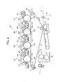
- FIG. 1 is a schematic block diagram illustrating a copier according to an example embodiment of the present invention
- FIG. 2 is a schematic block diagram illustrating an enlarged view of a selected portion of a printer of the copier of FIG. 1 ;
- FIG. 3 is a schematic block diagram illustrating an enlarged view of two image forming units of the printer of FIG. 2 ;
- FIG. 4 is a view illustrating a section of the image forming unit of FIG. 3 , viewed from the top;
- FIG. 5 is a plan view illustrating an intermediate transfer belt and an optical sensor unit in the printer of FIG. 2 ;
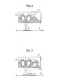
- FIG. 6 is a schematic block diagram illustrating a first optical sensor in the optical sensor unit of FIG. 5 ;
- FIG. 7 is a schematic block diagram illustrating a second optical sensor in the optical sensor unit of FIG. 5 ;
- FIG. 8 is a schematic block diagram illustrating electric connections of various units in the copier of FIG. 2 ;
- FIG. 9 is a flowchart illustrating operation of performing colour stabilization process to improve colour stability of an image, performed by the copier of FIG. 1 , according to an example embodiment of the present invention
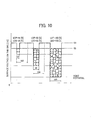
- FIG. 10 is an illustration for explaining the relationship between the laser outputs of a latent-image writing unit of the copier of FIG. 1 and the halftone ratios of an image;
- FIG. 11A is a graph illustrating the change in estimated output value of halftone ratio with respect to the target halftone ratio for the cyan toner image, as the colour stabilization process of FIG. 9 is performed;
- FIG. 11B is a graph illustrating the change in estimated output value of halftone ratio with respect to the target halftone ratio for the magenta toner image, as the colour stabilization process of FIG. 9 is performed;
- FIG. 11C is a graph illustrating the change in estimated output value of halftone ratio with respect to the target halftone ratio for the yellow toner image, as the colour stabilization process of FIG. 9 is performed;
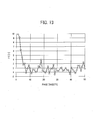
- FIG. 12A is a graph illustrating the change in estimated output value of L* and measured output values of L*, with respect to the target L* value for the cyan toner image, as the colour stabilization process of FIG. 9 is performed;
- FIG. 12B is a graph illustrating the change in estimated output value of a* and measured output values of a*, with respect to the target a* value for the magenta toner image, as the colour stabilization process of FIG. 9 is performed;
- FIG. 12C is a graph illustrating the change in estimated output value of b* and measured output values of b*, with respect to the target b* value for the yellow toner image, as the colour stabilization process of FIG. 9 is performed;
- FIG. 13 is a graph illustrating the change in colour difference between the output value of grayscale image and the target value of grayscale image, as the colour stabilization process of FIG. 9 is performed.
- FIGs. 14A to 14B are a list of equations illustrating calculation performed by a main controller of FIG. 8 in colour stabilization process, according to an example embodiment of the present invention.
- the image forming apparatus is implemented by a copier 600.
- the copier 600 includes, a printer 100 that forms an image on a recording sheet P, a sheet feeding device 200 that supplies the recording sheet P to the printer 100, a scanner 300 mounted on the printer 100, and an automatic document feeder (ADF) 400 mounted on the scanner 300.
- the printer 100 is provided with a manual sheet feed tray 6 and a sheet discharge tray 7.
- the manual sheet feed tray 6 receives a recording sheet P manually fed by a user, which is to be transferred to the inside of the printer 100.
- the printed sheet P having the toner image formed thereon is discharged from the printer 100 onto the sheet discharge tray 7.
- a set of original documents to be copied are placed onto a document tray 30 of the ADF 400. If the original documents are bound together, the original documents are placed on an exposure glass 31 of the scanner 300. When the ADF 400 is opened with respect to the exposure glass 31, the exposure glass 31 is exposed to the user. The user may place the original documents thereon while making a page to be copied to be faced downward, and closes the ADF 400 such that the original documents are placed against the exposure glass 31.
- the scanner 300 drives a first scanner body 33 such that a light beam irradiated from a light source of the first scanner body 33 is scanned through a document surface via the exposure glass 31.
- the light beam is reflected by the document surface to generate a reflective light.
- the ADF 400 automatically conveys the documents, one sheet by one sheet, to an image reader section 401 that is provided at left sides of the exposure glass 31.
- the document sheet is conveyed to a document discharge tray 30a after the document sheet passes the image reader section 401 where an image on the document sheet is read.
- the scanner 300 keeps the first scanner body 33 at a position below the image reader section 401. The light beam irradiated from the first scanning body 33 is thus reflected by the document surface of the document sheet as the document sheet passes the image reading section 401.
- the scanner 300 further includes a second scanner body 34 having a mirror that deflects the reflective light received from the document surface toward a reading sensor 36 through an imaging lens 35.
- the reading sensor 36 forms thereon an optical image, which is sent to the printer 100 after being converted to image data.
- the printer 100 forms an image on the recording sheet P based on the image data read by the scanner 300.
- the printer 100 may form an image on a recording sheet based on image data that is received from an external apparatus such as a personal computer.
- the sheet feeding device 200 includes a plurality of sheet cassettes 44, a plurality of sheet feed rollers 42, a plurality of pairs of separating rollers 45, and a plurality of pair of transfer rollers 47.
- the sheet cassette 44 stores therein a stack of recording sheets P. With the sheet feed roller 44 and the separating roller pair 45, the recording sheet P that is placed at the top of stack is fed from the sheet cassette 44 toward a sheet feed path 46.
- the sheet transfer rollers 47 transfer the recording sheet P along the sheet feed path 46 to a sheet conveying path 48.
- the sheet feed roller 42 of selected one of the sheet cassettes 44 rotates to feed the recording sheet P from the sheet cassette 44. Selection of the cassette 44 may be made according to a user instruction.
- the recording sheet P which is separated by the separating roller pair 45 from the rest of the recording sheets, is fed to the sheet feed path 46.
- the recording sheet P is further transferred by the transfer rollers 47 to the sheet conveying path 48 in the printer 100.
- FIG. 2 is an enlarged view illustrating a selected portion of the printer 100 of FIG. 1 .
- the printer 100 includes an intermediate transfer body, such as an intermediate transfer belt 10.
- the intermediate transfer belt 10, which is an endless belt, is made of any material that is high in mechanical strength such that the misregistration that may be caused due to stretching of the belt is suppressed.
- polyimide (PI) may be used as a base substrate of the intermediate transfer belt 10.
- carbon which functions as a resistant adjusting agent, is dispersed over the surface of the base substrate of the intermediate transfer belt 10.
- the surface of the intermediate transfer belt 10 has a black colour.
- the intermediate transfer belt 10 may be made of polyvinylidence fluoride (PVDF), without carbon being dispersed over the belt surface.
- PVDF polyvinylidence fluoride
- the printer 100 further includes a plurality of rollers such as a first support roller 14, a second support roller 15, and a third support roller 16.
- the intermediate transfer belt 10 is wound around these rollers so as to be stretched to form a loop having an inversed triangle shape when viewed from the side.
- the loop made by the intermediate transfer belt 10 has a horizontally stretched surface.
- the intermediate transfer belt 10 moves in a counterclockwise direction as indicated by the arrow A in FIGs. 1 and 2 .
- the image forming units 18Y, 18C, 18M, and 18K are disposed, side by side, along the horizontally stretched surface of the intermediate transfer belt 10.
- the image forming units 18Y, 18C, 18M, and 18K respectively form toner images of yellow (Y), cyan (C), magenta (M), and black (K) colours.
- a latent-image writing unit 21 is provided ( FIG. 1 ).
- the latent-image writing unit 21 receives image data of the original document that is read by the scanner 300, or image data transmitted from the external apparatus, under control of a writing controller provided in the latent-image writing unit 21.
- the latent-image writing unit 21 drives semiconductor laser sources respectively provided for Y, C, M, and K, to irradiate and scan the laser beams for writing the Y image, C image, M image, and K image, toward the respective surfaces of photoconductors 20Y, 20C, 20M, and 20K of the image forming units 18Y, 18C, 18M, and 18K, thus forming latent images of Y, C, M, and K onto the surfaces of the photoconductors 20Y, 20C, 20M, and 20K.
- any desired light source such as LED may be used.
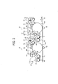
- FIG. 3 is an enlarged view illustrating the image forming units 18 that are adjacent with each other, which are selected from the image forming units 18 of the printer 100 shown in FIG. 2 .
- the references Y, M, C, and K are omitted.
- the image forming unit 18 includes a charging device 60, a developing device 61, a cleaning device 63, and a discharging device 64, which are arranged in the circumferential direction of the photoconductor 20 of drum-like shape.
- the charging device 60 charges the surface of the photoconductor 20, which is rotated in the counterclockwise direction, with the same polarity as a charging polarity of toner.
- the charging device 60 is implemented by a charging roller of non-contact type, which is disposed at a position close to the surface of the photoconductor 20.
- the charging device 60 is applied with a charging bias to generate electrical discharge between the photoconductor 20 and the charging device 60. With this electrical discharge, the surface of the photoconductor 20 is uniformly charged.
- a scorotron charger of non-contact type may be used as the charging device 60.
- FIG. 4 illustrates the inside of the developing device 61, viewed from the top when the upper part of a casing of the developing device 61 is removed.
- the developing device 61 develops the latent image formed on the photoconductor 20 into toner image, using a developing agent, i.e., developer, including magnetic carriers and non-magnetic toner.
- a developing agent i.e., developer
- the developing device 61 is mainly classified into an agitator section 66 and a developer section 67.
- the agitator section 66 is provided with two conveying screws 68 that are arranged in parallel with each other. These two conveying screws 68 are separated by a separating wall 69 such that the conveying screws 68 are placed in different rooms.
- the separating wall 69 includes notches at its both ends along the longitudinal direction of the screws 68. Through the notches, these two rooms each storing the conveying screw 68 therein are communicated. Of these two rooms, the room that is adjacent with the developer section 67 is a feed chamber. The developer in the feed chamber is applied to a developing sleeve 65 in the developer section 67. The other room is a return chamber. The developer fed from the feed chamber returns to the return chamber at one end in the longitudinal direction of the screws 68. The developer is then supplied from the return chamber to the feed chamber at the other end in the longitudinal direction of the screws 68.
- the conveying screw 68 in the feed chamber and the conveying screw 68 in the return chamber are rotated so as to convey the developer in the opposing directions such that the developer conveyed near the end of the screws 68 in the longitudinal direction is further conveyed into the other chamber through the notches.
- the developer in the developing device 61 is circulated between the feed chamber and the return chamber.
- the agitator section 66 includes a toner density sensor 71 at a bottom surface of the feed chamber, which detects toner density of the developer.
- the notches which allow the lower ends in the conveying direction in the feed chamber and the upper ends in the conveying direction in the return chamber to be communicated, are formed with a toner supply port 61a.
- the developer section 67 houses therein the developing sleeve 65 made of a rotatable, nonmagnetic pipe.
- a magnet roller having a plurality of circuznferentially-arranged magnetic poles is provided in the developing sleeve 65 and fixed there in a manner such that the magnet roller is not rotated even when the developing sleeve 65 rotates.
- the developer is conveyed in a direction indicated by the arrow B in FIG. 4 as the conveying screw 68 rotates.
- the toner density sensor 71 detects the toner density of the developer being conveyed.
- a part of the developer is lifted up toward the developing sleeve 65 by a magnetic force exerted by the magnet roller in the developing sleeve 65.
- the developer lifted up toward the surface of the developing sleeve 65 is transferred by rotation of the developing sleeve 65 to a developing area where the developing sleeve 65 and the photoconductor 20 face with each other.
- a doctor blade 73 regulates a thickness of the developer formed on the developing sleeve 65.
- a development potential causes toner particles in the developer to be separated from the magnetic carriers in the developer, and transferred onto a latent image formed on the photoconductor 20.
- the development potential is a voltage difference between the developing sleeve 65, onto which the developing bias voltage of the same polarity as the polarity of the charge on the toner is applied, and the latent image formed on the surface of the photoconductor 20.
- the electrostatic latent image on the photoconductor 20 is thus developed into toner image.
- the developer that has passed through the developing area is further conveyed by rotation of the developing sleeve 65 to a position of a repulsive magnet pole in the magnet roller, the developer is released from the surface of the developing sleeve 65 and returned into the feed chamber in the agitator section 66.
- the toner density in the developer decreases.
- This decrease in toner density is detected by the toner density sensor 71. Based on this detection result, an appropriate amount of toner is supplied from the toner supply port 61a into the feed chamber.
- the toner supply control based on the detection result of the toner density sensor 71 is performed each time as one sheet is fed.
- four primary transfer rollers 62Y, 62C, 62M, and 62K are arranged inside the loop of the intermediate transfer belt 10 so as to face the four photoconductors 20 via the intermediate transfer belt 10.
- the primary transfer roller 62 presses an outer surface of the intermediate transfer belt 10 against the photoconductor 20, thereby forming a primary transfer nip where the outer surface of the belt and the photoconductor 20 are in contact with each other.
- a primary transfer bias having a polarity opposite of the toner charging polarity is applied onto the primary transfer roller 62, thus forming a primary transfer electric field at the primary transfer nip.
- any desired primary transfer unit for transferring a toner image on the photoconductor 20 onto the outer surface of the intermediate transfer belt 10 may be used, for example, a transfer brush, or a non-contact corona charger.
- Transfer-residual toner which is not primary-transferred onto the intermediate transfer belt 10, remains deposited on the surface of the photoconductor 20 that has passed through the primary transfer nip.
- the cleaning device 63 removes this transfer-residual toner from the surface of the photoconductor 20.
- the cleaning device 63 supports a cleaning blade 75 made of a polyurethane rubber at one end of the cleaning blade 75. The cleaning device 63 scrapes off the transfer-residual toner from the surface of the photoconductor 20 by bringing the other, free end of the cleaning blade 75 into contact with the surface.
- a conductive fur brush 76 that rotates while being in contact with the surface of the photoconductor 20 also removes the transfer-residual toner from the surface of the photoconductor 20.
- the toner removed from the surface of the photoconductor 20 by the cleaning blade 75 and the fur brush 76 is stored in the cleaning device 63 at least temporarily.
- the photoconductor 20 is made of a drum-like shape that is 60 mm in diameter.
- the photoconductor 20 is rotated counterclockwise in FIG. 3 at a linear velocity of 282 mm/sec.
- the developing sleeve 65 is made of a columnar shape that is 25 mm in diameter, and is rotated at a linear velocity of 564 mm/sec.
- An amount of charge on the toner in the developer in the developing device 61 to be supplied to the developing area is approximately in a range between -10 and - 30 ⁇ C/g.
- a thickness of a photosensitive layer on the photoconductor 20 is 30 ⁇ m; the beam spot diameter and a power of a laser beam emitted from an optical system of the latent-image writing unit 21 is 50 ⁇ 60 ⁇ m and approximately 0.47 mW, respectively.
- the surface of the photoconductor 20 is uniformly charged by the charging device 60 to, for instance, -700 V; the electrostatic potential at a portion of an electrostatic latent image irradiated with the laser beam emitted from the latent-image writing unit 21 becomes -120 V.
- the developing bias voltage applied to the developing sleeve 65 is-470 V. Accordingly, a developing potential of -350 V is applied on the toner on the electrostatic latent image on the photoconductor 20.
- the photoconductor 20 is uniformly charged by the charging device 60 while being rotated, and optically scanned by the latent-image writing unit 21, thus forming an electrostatic latent image on the photoconductor 20.
- This optical scanning is performed based on image data read by the scanner 300 or image data transmitted from the external apparatus.
- the electrostatic latent image formed on the photoconductor 20 is developed by the developing device 61 into a toner image.
- the toner image is primary-transferred onto the intermediate transfer belt 10 by the primary transfer electrical field, which is formed between the photoconductor 20 and the primary transfer roller 62. Transfer-residual toner that resides on the surface of the photoconductor 20 is removed by the cleaning device 63.
- the surface of the photoconductor 20 undergoes electrostatic discharging performed by the discharging device 64 to become ready for a subsequent image forming process.
- the printer 100 further includes a secondary transfer roller 24, which is provided outside the loop of the intermediate transfer belt 10.
- the intermediate transfer belt 10 is pinched between the secondary transfer roller 24 and the third support roller 16, which is inside the belt loop.
- the third support roller 16 presses the intermediate transfer belt 10 against the secondary transfer roller 24, thereby forming a secondary transfer nip where the outer surface of the belt and the secondary transfer roller 24 are in contact with each other.
- the latent-image writing unit 21 emits image writing lights to the photoconductors 20Y, 20C, 20M, and 20K of the image forming units 18Y, 18C, 18M, and 18K based on the image data read with the reading sensor 36 of the scanner 300 or the image data received from the external apparatus. As a result, an electrostatic latent image is formed on each of the photoconductors 20Y, 20C, 20M, and 20K.
- the electrostatic latent images are developed by the developing devices 61Y, 61C, 61M, and 61K such that a Y-toner image, a C-toner image, an M-toner image, and a K-toner image are formed on the photoconductors 20Y, 20C, 20M, and 20K.
- the formed toner images are primary-transferred onto the intermediate transfer belt 10 at primary transfer nips for yellow, cyan, magenta, and black to be superimposed one above the other.
- four-colour superimposed toner image in which toner images of respective colours are superimposed one above the other, is formed on the intermediate transfer belt 10.
- each one of the black, magenta, cyan, and yellow images may be referred to as the primary colour image as the image is formed with one type of toner.
- the recording sheet P fed out from the sheet feeding device 200 is conveyed into the sheet conveying path 48 in the printer 100, and stopped at a position where the recording sheet P abuts on a pair of registration rollers 49.
- the pair of registration rollers 49 which receives the recording sheet P on the sheet conveying path 48, feeds out the recording sheet P to the secondary transfer nip at a timing such that the recording sheet P reaches the secondary transfer nip when the four-colour superimposed toner image formed on the intermediate transfer belt 10 reaches the secondary transfer nip.
- the secondary transfer electrical field formed between the secondary transfer roller 24 and the third support roller 16 the four-colour superimposed toner image is transferred onto the recording sheet P, which is conveyed into the secondary transfer nip.
- the four-colour superimposed toner image on the recording sheet P becomes a full-colour toner image, which may be referred to as a multi-colour toner image, by cooperating with a white background of the recording sheet P.
- the recording sheet P is conveyed to a fixing device 25 where the full-colour toner image is fixed to the recording sheet P by heat and pressure at a fixing nip formed between a heating roller 26 and a fixing roller 27.
- the recording sheet P that has passed through the fixing device 25 is conveyed either to a direction toward a sheet-reversing device 93 and a direction toward a pair of discharging rollers 56, as switched by a flapper.
- the recording sheet P is conveyed into the sheet-reversing device 93, the recording sheet P is conveyed to the pair of registration rollers 49, after being reversed, to form a full-colour image on the other side of the recording sheet P. If the recording sheet P is conveyed to the pair of discharging rollers 56, the recording sheet P is stacked on the sheet discharge tray 7 that is provided outside the copier 600.
- any desired secondary transfer unit for secondary-transferring the four-colour superimposed toner image formed on the intermediate transfer belt 10 onto the recording sheet P may be used, for example, a transfer charger.
- the printer 100 further includes a roller cleaning unit 91, which is made in contact with the secondary transfer roller 24, to clean toner that resides on the secondary transfer roller 24 after secondary transfer of the image.
- the printer 100 further includes a belt cleaning device 17, which is provided at a section that wounds around the second support roller 15 in a manner that is made in contact with that section of the belt.
- the belt cleaning device 17 cleans transfer-residual toner that resides on the surface of the intermediate transfer belt 10, which passes the secondary transfer nip.
- the printer 100 further includes a manual sheet feed path 41, which extends from the manual feed tray 6 and merges with the sheet conveying path 48. At an upstream portion of the manual sheet feed path, a sheet feed roller 601 and a separation roller 602 are provided for feeding the recording sheet P placed on the manual feed tray 6 one sheet at a time.
- a line spectrometer 900 (hereinafter, referred to as "spectrometer") is provided above the sheet discharge tray 7.
- the spectrometer 900 measures colours of a toner image formed on the recording sheet P that is discharged onto the sheet discharge tray 7. More specifically, the spectrometer 900 obtains a distribution of spectral reflectance from the toner image formed on the recording sheet P. Assuming that a length in the main scanning direction of an image forming area that corresponds to a A4 size recording sheet P ranges between 0 mm to 210 mm, the spectrometer 900 detects spectral reflectance at a total of 22 positions in the main scanning direction length, which are each incremented by 10 mm.
- the spectrometer 900 is able to detect spectral reflectance in the wavelength range between 400 nm and 700 nm, which is incremented by 10 nm into 31 wavelength values. Further, the spectrometer 900 detects spectral reflectance in the sub-scanning direction, that is, the sheet conveying direction, for each position that is incremented by 10 mm. For each of 22 positions in the main scanning direction length at which spectral reflectance is detected, colours of a square-shaped area of 10 mm by 10 mm are measured, such that 22 colour measurements are obtained from the printed image. The spectral reflectance distribution of colours in the printed image is an average value of the 22 colour measurements obtained from the square-shaped areas.
- an optical sensor unit 310 is provided outside the loop of the intermediate transfer belt 10 in a manner that the optical sensor unit 310 faces a portion of the intermediate transfer belt 10 supported on the first support roller 14 via a predetermined distance.
- FIG. 5 illustrates the horizontally stretched surface of the intermediate transfer belt 10 and the optical sensor unit 310, when viewed from the top.
- the optical sensor unit 310 includes a first optical sensor 311 for measuring a black toner patch image Pk, and a second optical sensor 312 for measuring a magenta toner patch image Pm, cyan toner patch image Pc, and yellow toner patch image Py, which are arranged along a width direction of the belt.
- the belt width direction is the direction that is perpendicular to the arrow A in FIG. 5 .
- the second optical sensor 312 is located at a position closer to a center of the belt than the first optical sensor 311 is. This position that is closer to the belt center corresponds to an upstream position in a developer conveyance direction indicated by the arrow B in FIG. 4 , along which the conveying screw 68 in the supply chamber conveys the developer to the developing sleeve 65 in the developing area.
- the toner image developed by the developing device 61 tends to have different values of image density across the toner image surface. More specifically, a portion of the toner image that corresponds to a position that is upstream in the developer conveying direction in the developing area tends to have a higher image density than that of a portion of the toner image that corresponds to a position that is downstream in the developer conveying direction. This is because toner that is relatively low in charging capability tends to be developed upstream in the developer conveying direction, and the height of the developer formed on the developing sleeve 65 tends to be higher in upstream than in downstream.
- the adhesion amount of toner on the patch images will be different, depending on its position in the main scanning direction along the developing sleeve 65.
- the positions of the first optical sensor 311 and the second optical sensor 312 may be each set, while taking into account a specific position in the main scanning direction that needs to be controlled.
- the position at which each patch image is formed may be controlled, if only a limited number of patch images are to be formed. For example, when the sensor is positioned upstream in the developer conveying direction in the developing area, the patch images having high image density will be subjected for measurement such that the patch images detected in downstream of the measured area tend to have lower image densities than that of the measured patch images.
- the upstream position of the sensor is desirable when troubles due to low charging capability of toner are to be controlled, such as scattering of toner within a device of the copier 600 such as the developing device 61.
- the upstream developer may not be sufficiently agitated such that charging capabilities of toner contained in the upstream developer tend to be large in variance while being unstable.
- the sensor position should be a position that is sufficiently downstream to obtain measurements that are more reliable from patch images developed with toner having stable charging capability values, but is sufficiently upstream to obtain measurements from patch images with high image density values.
- FIG. 6 illustrates an enlarged section of the first optical sensor 311.
- FIG. 7 illustrates an enlarged section of the second optical sensor 312.
- the first optical sensor 311 measures a toner adhesion amount per unit area of the black toner patch image Pk formed on the intermediate transfer belt 10.
- the first optical sensor 311 includes a light source (LED) 311 a, such as a LED, which emits light toward the intermediate transfer belt 10, and a first sensor specular-reflection-light receiving element 311b that receives light specularly reflected from the intermediate transfer belt 10.
- the second optical sensor 312 measures a toner adhesion amount per unit area of each of the yellow toner patch image Py, cyan toner patch image Pc, and magenta toner patch image Pm respectively formed on the intermediate transfer belt 10. As illustrated in FIG.
- the second optical sensor 312 includes a light source 312a, such as a LED, which emits light toward the intermediate transfer belt 10, a specular-reflection-light receiving element 312b that receives light specularly reflected from the intermediate transfer belt 10, and a diffuse-reflection-light receiving element 312c that receives diffuse reflection light from the intermediate transfer belt 10.
- a light source 312a such as a LED
- specular-reflection-light receiving element 312b that receives light specularly reflected from the intermediate transfer belt 10
- a diffuse-reflection-light receiving element 312c that receives diffuse reflection light from the intermediate transfer belt 10.
- Each of the light sources 311 a and 312a uses a GaAs infrared-emitting diode whose peak emission wavelength ⁇ p is 950 nm.
- the receiving elements 311b, 312b, and 312c are each implemented by a light-receiving element, which is a Si phototransistor whose peak receipt wavelength is 800
- the optical sensors 311 and 312 are located so as to be away from the intermediate transfer belt 10, which is a measurement target surface, by a distance (detection distance) of 5 mm.
- the optical sensor unit 310 includes, in addition to the optical sensors, a sensor memory 313 ( FIG. 5 ).
- FIG. 8 is a schematic block diagram illustrating electrical connections of units in the copier 600 that are related to operation of controlling colour stability of an image.
- the copier 600 includes a main controller 500, which controls operation of the units in the copier 600.
- the main controller 500 includes a central processing unit (CPU) 501 that performs various computations and drive control of the units, a read only memory (ROM) 503 that stores various data such as computer program instructions, and a random access memory (RAM) 504 that stores various data in a rewritable manner to serve as a working area of the CPU 501, which are connected via a bus line 502.
- the main controller 500 is connected to various units or devices in the printer 100 such as the sheet feeding device 200, the scanner 300, and the ADF 400.
- the optical sensor unit 310 and the line spectrometer 900 of the printer 100 output measurement results to the main controller 500.
- the main controller 500 performs the toner adhesion-amount stabilization process based on the measurement results obtained from the printed image, as an example of colour stabilization process. More specifically, the main controller 500 causes a colour stabilization control program, which is previously stored in the ROM 503, to be loaded onto the RAM 504 for execution by the CPU 501.
- the colours of the multi-colour toner image formed on the recording sheet are measured, and compared with the target colours of the multi-colour toner image that are previously determined.
- the image forming conditions of the primary colour toner images that constitute the multi-colour toner image are corrected such that the measured colours of the multi-colour toner image reaches the target colours of the multi-colour toner image.
- the copier 600 estimates a developing density of each of the primary colours constituting the multi-colours in the multi-colour toner image, from the measured multi-colours in the multi-colour toner image formed on the recording sheet P. Using this colour stabilization process, colours of the output image can be stabilized while greatly reducing the needs for outputting patch images.
- the copier 600 causes the spectrometer 900 to obtain information regarding the multi-colours of a multi-colour toner image that is printed as a user image, as multi-colour information.
- the main controller 500 estimates information regarding each of the primary colours Y, M, C, and K that constitute the multi-colours of the multi-colour toner image being output, as primary colour information.
- the main controller 500 determines correction values of control parameters that control image forming conditions of the copier 600, based on the difference between the estimated primary colour information estimated from the multi-colour information of the measurement result, and target primary colour information previously obtained.
- the main controller 500 further corrects the control parameters such as control parameters regarding the image forming unit 18 or the latent-image writing unit 21, using the determined correction values.
- the control parameters to be corrected include, for example, a target control value of toner density in the developing device 61, a developing bias (Vb), a light intensity (LDP) of the image writing light that is irradiated by the latent-image writing unit 21 onto the surface of the photoconductor 20.
- FIG. 9 is a flowchart illustrating operation of performing colour stabilization process, performed by the copier 600, according to an example embodiment of the present invention.
- the main controller 500 obtains input image data, which may be obtained by the scanner 300 or transmitted from the external apparatus.
- the image data contains pixel values each representing lightness of a single-colour component of red (R), green (G), and blue (B) for each of a plurality of pixels arranged in a matrix.
- the main controller 500 converts the image data into image data containing pixel values each representing lightness of a single-colour component of cyan (C), magenta (M), yellow (Y), and black (K).
- the main controller 500 After conversion of the image data, the main controller 500 concurrently performs the following two operations.
- One operation is printing operation, which includes image forming at S2 and transferring at S3.
- the other operation is operation for determining a measurement area to be measured by the spectrometer 900, which is performed at S4.
- the multi-colour toner image formed on the intermediate transfer belt 10 is transferred to the recording sheet P at the secondary transfer nip.
- the recording sheet P having the multi-colour toner image fixed thereon by the fixing device 25 is further output onto the sheet discharging tray 7.
- the main controller 500 searches an entire section of an image, which is to be formed based on the image data, for a suitable colour measurement area that is subjected for colour measurement.
- the operation proceeds to S5 to measure colours of the colour measurement area in the multi-colour toner image formed on the recording sheet P.
- the spectrometer 900 measures colours in the colour measurement area selected from the entire section of the multi-colour toner image that is formed on the recording sheet P as the recording sheet P is output below the spectrometer 900.
- the copier 600 selects a portion of the entire image as a measurement area subjected for colour measurement, measures multi-colours in the selected measurement area of the output image to output a measurement result, estimates primary colours from the measurement result as measured primary colours, and compares the estimated primary colours that are generated based on the measurement result with the primary colours obtained from the image data used for image forming.
- the copier 600 may divide the entire image into a plurality of measurement areas, and performs colour measurement and comparison for each of the measurement areas.
- processing the entire image requires a processor with high-processing capability such that the overall manufacturing costs may increase. This may further increase the processing time.
- the main controller 500 of the copier 600 searches the entire image for a measurement area that is most suitable for colour measurement based on information obtainable from the image data.
- the measurement area suitable for colour measurement is an area that is high in flatness in colour, or low in colour variance.
- the spectrometer 900 measures colours in the selected measurement area of the output image output by the printer 100 to generate a measurement result.
- the main controller 500 compares between the colours obtained from the measurement result with the colours obtained from the image data.
- the colour measurement area is searched as described below.
- the main controller 500 selects a pixel, which is located at a predetermined position in a pixel matrix represented by the image data, as a target pixel.
- the main controller 500 further extracts an area having the target pixel at its center and a predetermined size as a subarea. For example, for the first time of extraction, a pixel located on the 5 1 st row, the 5 1 st column from an upper-left corner of the pixel matrix is set as the target pixel; a rectangular area of 101 pixels by 101 pixels (an area of approximately 4 mm per side) where the target pixel is at its center is extracted as the subarea.
- the main controller 500 calculates flatness indicating the degree of flatness in colour tones, or the degree of flatness in lightness, of colour through the entire section of the subarea, by referring to the pixel values (C, M, Y, and K) of each pixel in the extracted subarea.
- the flatness may be calculated in various ways. In one example, for each colour components of C, M, Y, and K, variance of pixel values is obtained. The flatness in the extracted subarea is obtained as a negative value of the sum of variance of pixel values obtained for C, M, Y, and K colour components.
- the flatness in the extracted subarea is obtained using variance-covariance matrix. More specifically, variance and covariance of each pixel in the subarea are calculated for each colour components of C, M, Y, and K. The variance and the covariance are respectively positioned as diagonal elements and non-diagonal elements to construct the 4X4 variance-covariance matrix. The flatness in the extracted subarea is obtained as a negative value of a solution to this variance-covariance matrix.
- the variance-covariance matrix is able to evaluate distribution of colours in the CMYK colour space even among different colour components.
- the flatness in the extracted subarea is obtained using frequency characteristics of colours. More specifically, the pixel value of each pixel in the extracted subarea is applied with Fourier transformation to obtain the squared sum of the absolute value of Fourier coefficients of a specific frequency. The flatness is obtained as a negative value of this squared sum. In this example, for the specific frequency, more than one frequency may be used. In the above-described example of obtaining the sum of variance of pixel values, for images with halftone processing, the flat area may not be accurately detected due to halftone patterns in the image. In contrary, in the example of obtaining the flatness using the frequency characteristics, the use of squared sum of absolute values of Fourier coefficients is not affected by halftone patterns in the image.
- the main controller 500 determines whether all subareas to be extracted have been extracted, or area extraction is completed for the entire image. When it is determined that there is a subarea to be extracted, the main controller 500 shifts the position of a target pixel by one pixel to the right to select a pixel on the 52nd row, the 52nd column from the upper-left corner of the pixel matrix as a target pixel. The main controller 500 further extracts a rectangular area of 101 pixels by 101 pixels having the target pixel at its center as a subarea. The flatness of colours of the extracted subarea is calculated in a similar manner.
- the position of the target pixel is shifted to the right by one pixel.
- the position of the target pixel in the row direction is returned to the position at 51 st from a left end to the right of the matrix and simultaneously the position of the target pixel in the column direction is shifted downward by one pixel.
- the operation of shifting the position of the target pixel to the right by one pixel is repeated.
- the position of the target pixel is shifted one by one as discussed above as in raster scanning to perform extraction across the entire image.
- a subarea to be processed may be extracted from the entire image such that the subarea does not overlap with the adjacent subarea that has been previously extracted. For example, after the rectangular area of 101 pixels by 101 pixels having the 51 st row, 51 st column, target pixel as its center is extracted, a rectangular area of 101 pixels by 101 pixels having the 152nd row, 152nd column target pixel as its center may be extracted.
- the main controller 500 selects one of the extracted subareas having the flatness that is most desirable, and determines whether the flatness of the selected extracted subarea is more desirable than a reference flatness value that is previously determined. When it is determined that the flatness of the selected extracted subarea is more desirable than the reference flatness value, the main controller 500 determines that the extracted subarea having the flatness that is more desirable is applicable to colour measurement. When it is determined that the flatness of the selected extracted subarea is less desirable than the reference flatness value, the main controller 500 determines that there is no area that is suitable for colour measurement at least for the image data to be output.
- the main controller 500 may perform colour stabilization process using any known method, thus suppressing the degradation in colour stability in image.
- the main controller 500 causes the primary colour toner patch images Py, Pc, Pm, and Pk to be formed on the intermediate transfer belt 10.
- the optical sensor unit 310 determines toner adhesion amount per unit area of each of the Y, C, M, and K toners on the toner patch images Py, Pc, Pm, and Pk, based on the detection results of the optical sensors that are output as the toner patch images pass across a position immediately below the optical sensors.
- the main controller 500 compares a calculated value of the Y-toner adhesion amount against a target Y-toner adhesion amount.
- a target Y-toner concentration control value for use in toner supply control is increased. If the calculated amount is greater than the target amount, the target Y-toner concentration control value is lowered.
- target C-, M-, and K-toner concentration control values are corrected based on results of comparison between calculated values of the deposited C-, M-, and K-toner amount and target values for the same.
- the operation proceeds to S5 to cause the spectrometer 900 to measure multi-colours in the selected measurement area of the multi-colour toner image formed on the recording sheet P.
- the main controller 500 obtains estimated primary colour information indicating the estimated output value of each of the primary colours constituting the multi-colours in the multi-colour toner image, based on multi-colour information indicating the multi-colour that is obtained from the measurement result obtained at S5, using a colour separation model described below.
- the main controller 500 compares the estimated output value of each of the primary colours with a target value of each of the primary colours.
- the target value of each of the primary colours is determined based on the image data used for forming the primary colour image. Based on the comparison, the main controller 500 obtains correction values of control parameters that control image forming conditions, and correct the control parameters using the correction values.
- the control parameters to be corrected include a laser intensity (LDP) of the latent-image writing unit 21, an applied charge voltage (Cdc) applied by the charging device 60, and a developing bias voltage (Vb) of the developing device 61.
- the toner density of the developer stored in the developing device 61 may be used as control parameters.
- the main controller 500 estimates the primary colour information regarding a developing density of each one of the primary colour toner images that constitute the multi-colour toner image formed on the recording sheet. More specifically, the main controller 500 estimates an average value of halftone dot ratios ("the output halftone ratio") of each of the primary colour toner images constituting the multi-colour toner image, as primary colour information for each one of the primary colours.
- FIG. 10 illustrates the relationship between the parameters of the laser outputs of the latent-image writing unit 21 and the halftone ratios of an image.
- the parameters of the laser outputs of the latent-image writing unit 21, which are adjustable, are the power of the laser diode (LDP) and the duty cycle of the laser diode (LDD).
- the LDP is the laser intensity of the image writing light irradiated by the latent-image writing unit 21.
- the LDD is the time the latent-image writing unit 21 spends in irradiating the image writing light per unit time.
- the halftone ratio is a ratio of an area formed with a toner image over a unit area on a surface of the recording sheet P.
- the halftone ratio thus corresponds to a ratio of an area formed with a latent image over a unit area on the surface of the photoconductor 20, which is adjustable through control parameters of the laser outputs. For example, when the halftone ratio of the toner image is 50 %, the halftone ratio of the latent image is 50 %.
- the amount of toner being supplied onto the surface of the photoconductor 20 increases, thus increasing the image density.
- the value of LDP and the value of LDD may be changed independently from each other. That is, the image density may be changed with the change in at least one of the LDP and the LDD. Even when the value of LDP remains the same, the image density increases with the increase in LDD. Even when the value of LDD remains the same, the image density increases with the increase in LDP. It is, however, more common to control the image density through changing the value of LDD to obtain gradation in image, and adjust the value of LDP such that a solid image has a predetermined density when LDD is 10 %. In the following examples, however, the copier 600 actively changes the value of LDP as control parameter value.
- the copier 600 sets an initial value of LDP to be lower than the maximum value of LDP, for example, to 70 %.
- the value of LDP i.e., the laser intensity, may be adjusted as needed.
- the control parameter value is not corrected, the LDP value is fixed. Under the fixed LDP value, the value of halftone ratio subjected for control is set such that a desired image density is obtained.
- a toner image formed on a recording sheet P has a toner adhesion amount per one pixel that corresponds to the laser intensity of 70 %, and has an area of 40 % with respect to the overall surface of the recording sheet P.
- the output halftone ratio of the toner image output from the copier 600 which may be referred to as the target halftone ratio, is 40 %.
- the output halftone ratio of the toner image output from the copier 600 is less than 40 %.
- the main controller 500 corrects a control parameter for adjusting the laser intensity based on comparison between the output halftone ratio and the target halftone ratio, thus stabilizing the toner adhesion amount. For example, when the output halftone ratio is less than the target halftone ratio, the control parameter is adjusted to increase the laser intensity, thus increasing the toner adhesion amount. When the output halftone ratio is greater than the target halftone ratio, the control parameter is adjusted to decrease the laser intensity, thus decreasing the toner adhesion amount.
- the primary colour information of each of the primary colours constituting the multi-colours can be compared with the primary colour information of each of the primary colours that is obtained from the image data used for image forming (target halftone ratio). Since the toner image formed on the recording sheet P is formed in multi-colours, information regarding the primary colours of the output toner image, or the output halftone ratio, cannot be measured. For this reasons, the main controller 500 estimates the output halftone ratio of each of the primary colours, based on the multi-colour information indicating the multi-colours in the multi-colour toner image that are measured by the spectrometer 900. The main controller 500 further compares, for each one of the primary colours, the estimated output halftone ratio with the target halftone ratio to obtain a correction value of the control parameter for laser intensity.
- the main controller 500 corrects the values of control parameters such as the control parameter for laser intensity (LDP), based on comparison between the output halftone ratio and the target halftone ratio obtained for each of the primary colours.
- the main controller 500 further corrects the values of control parameters for charge applying voltage and developing bias (Vb), using the correction value of the control parameter for laser intensity.
- the halftone ratios for the primary colours C, M, Y, and K are respectively expressed as kc, km, ky, and kk.
- the wavelength of the reflective light used for image writing for each of the primary colours is expressed as ⁇ (nm).
- the distributions of spectral reflectance for the halftone ratios of the colours C, M, Y, and K are respectively expressed as cyan (kc, ⁇ ), magenta (km, ⁇ ), yellow (ky, ⁇ ), and black (kk, ⁇ ).
- the spectral reflectance distribution is a distribution of reflectance obtained for various wavelength values of reflective lights when a white colour light is irradiated.
- the spectral reflectance distribution for each primary colour being obtained is applied with normalization in the wavelength range of 400 nm to 700 nm, such that, assuming that the spectral reflectance distribution of the white-colour recording sheet is white ( ⁇ ), white ( ⁇ ) is equal to 1 for all ranges of the wavelength ⁇ .
- the spectral reflectance distribution "magenta (0.5, ⁇ )" indicates a distribution of spectral reflectance of a magenta toner image formed on the white-colour recording sheet with a halftone ratio of 50 %.
- spectral reflectance is obtained for the wavelength values ranging between 400 nm and 700 nm, with the increment of 10 nm.
- the white-colour light is irradiated to the magenta toner image with the halftone ratio of 50 %
- reflectance of the reflective light is obtained for 31 different wavelength values of 400 nm, 410 nm, 420 nm, ..., and 700 nm.
- the spectral reflectance distribution "magenta (0.5, ⁇ )" can be thus expressed as a 31 X 1 matrix.
- the spectral reflectance distribution of the multi-colour toner image is defined to be "MixedColour ( ⁇ )".
- the spectral reflectance distribution of the multi-colour toner image is expressed as a product of the spectral reflectance distributions of primary colour toner images constituting the multi-colour toner image, as indicated by the equation 1 of FIG. 14A .
- the equation 1 of FIG. 14A which is the colour separation model, is defined to be the equation 2 of FIG. 14A .
- ⁇ 400 to ⁇ 700 respectively indicate the reflectance of the reflective lights having the wavelength values of 400 nm to 700 nm.
- the spectral reflectance distribution "MixedColour ( ⁇ )" corresponds to the multi-colours measured from the multi-colour toner image formed on the recording sheet P that is output from the copier 600.
- the output halftone ratio of each of the primary colours constituting the multi-colour toner image is supposed to be substantially the same as the target halftone ratio of each of the primary colours that is obtained from the image data, unless an image forming condition rapidly changes between the time when the image data is analyzed and the time when the image is formed based on the image data.
- the target halftone ratio is set at the time the latent image is formed, using information obtainable from the image data used for forming the latent image.
- the main controller 500 searches for a halftone ratio that is close in value to the target halftone ratio such that the difference "J" indicated by the equations 3 and 4 is made nearly “0" to obtain the estimated output value of halftone ratio of the primary colour constituting the multi-colour toner image being output.
- the copier 600 may use an algorithm for estimating the value of output halftone ratio of the primary colour.
- the algorithm To construct the algorithm, the spectral reflectance distributions cyan (kc, ⁇ ), magenta (km, ⁇ ), yellow (ky, ⁇ ), and black (kk, ⁇ ), each corresponding to the estimated output value of halftone ratio, need to be obtained for the primary colours C, M, Y, and K.
- the halftone ratio values for each primary colour are discretized by increments of 10 % such that 10 halftone ratio values of kc1 to kc10, km1 to km10, ky1 to ky10, and kkl to kk10 are obtained for cyan, magenta, yellow, and black.
- the spectral reflectance distribution of the primary colour with respect to 10 discrete halftone ratio values is stored in the primary colour data table. More specifically, the primary colour data table stores, for each of the discrete halftone ratios of each primary colour, the spectral reflectance distribution data that is obtained from the measurement result of the primary colour toner image having the corresponding halftone ratio.
- the primary colour data table is stored in the ROM 503.
- candidate values of estimated output halftone ratio are generated using the target halftone ratio that is obtained from the measurement area of the image data to be formed.
- the candidate estimated output values of halftone ratio are halftone ratio values that are close to the target halftone ratio value.
- the spectral reflectance distribution that corresponds to each one of the candidate estimated output values of halftone ratio is generated. For example, assuming that the target halftone ratio is 55 %, the spectral reflectance distribution is obtained for each of the candidate estimated output values of halftone ratio, such as the halftone ratio value of 50 %, the halftone ratio value of 60 %, etc.
- the spectral reflectance distributions of the candidate estimated output values of halftone ratio for the respective primary colours that is, cyan (kc, ⁇ ), magenta (km, ⁇ ), yellow (ky, ⁇ ), and black (kk, ⁇ ) are input to the equation 3 and the equation 4.
- cyan (kc, ⁇ ), magenta (km, ⁇ ), yellow (ky, ⁇ ), and black (kk, ⁇ ) are input to the equation 3 and the equation 4.
- one of the candidate estimated output values of halftone ratio that can minimize the difference "J" is obtained for each primary colour, as the estimated output value of halftone ratio for each primary colour.
- the spectral reflectance distribution of the multi-colour is defined to be equal to a product of the magenta spectral reflectance distribution "magenta (0.5, ⁇ )” and the yellow spectral reflectance distribution "yellow (0.5, ⁇ )", as indicated by the equation 5 of FIG. 14B .
- the spectral reflectance distribution for red colour toner image "red (0.5, ⁇ )" is expressed as a combination of magenta spectral reflectance distribution "magenta (0.5, ⁇ )” and yellow spectral reflectance distribution "yellow (0.5, ⁇ )".
- the total of 9 candidate estimated output values of halftone ratio are generated.
- the number of candidate estimated output values is, however, not limited to 9 such that more than 9 candidate estimated output values may be generated.
- the spectral reflectance distribution that corresponds to such candidate halftone ratio value may be obtained by interpolating the halftone ratio values that are registered in the primary colour data table.
- information obtained from the cyan primary colour data table that stores the spectral reflectance in association with 10 halftone ratios kc1 to kc10 is used.
- a potential value table is prepared, which is used for correcting the control parameters.
- the potential value table stores a set of table numbers and control parameter values. With the decrease in table number, the developing density decreases. With the increase in table number, the developing density increases.
- the main controller 500 compares the target halftone ratio obtained from the image data with the estimated output value of halftone ratio. When the target halftone ratio is greater than the estimated output halftone ratio, the table number is increased. When the target halftone ratio is less than the estimated output halftone ratio, the table number decreases.
- the main controller 500 searches the potential value table for control parameter values that correspond to the table number, which is increased or decreased, and changes an image forming condition according to the control parameter values. More specifically, the control parameters for the image forming unit 18 and the latent-image writing unit 21 are corrected based on the obtained control parameter values.
- the halftone ratio is used as the primary colour information. More specifically, the estimated output value of halftone ratio is used as the estimated primary colour information, and the target halftone ratio is used as the target primary colour information. In alternative to or in addition to the halftone ratios, any other information may be used as the estimated primary colour information and the target primary colour information.
- the primary colour data table stores, for each of the primary colours, a plurality of spectral reflectance distributions in association a plurality of halftone ratio values.
- the spectral reflectance distribution for the estimated output halftone ratio values and the target halftone ratio value can be calculated for each primary colour.
- L*a*b* values can be obtained using any desired known method.
- the L*a*b* values that correspond to the estimated output halftone ratios may be used as the estimated primary colour information
- the L*a*b* values that correspond to the target halftone ratio may be used as the target primary colour information.
- the image forming condition of the primary colour toner image is controlled.
- one colour component selected from L*, a*, and b* components may be only used, such as the colour component that is most sensitive to the change in toner adhesion amount.
- the a* value or the b* value may change.
- the other two colour components each have the values determined based on the determined value of one colour component such that the a* and the b* values remain the same when the L* value remains the same.
- the main controller 500 may use the L* value for analysis of the cyan colour, the a* value for analysis of the magenta colour, and the b* value for analysis of the yellow colour. Based on the comparison result in L*, a*, or b* value obtained for each primary colour, the main controller 500 determines whether the image density of the primary colour toner image is higher or lower than the desired image density.
- the above-described colour stabilization process was performed using a test apparatus that has the same structure as the copier 600.
- a 3-colour (“3C") grayscale image having the halftone ratio of 70 % is formed on a recording sheet P, while performing the above-described colour stabilization process.
- image forming is sequentially performed for 50 times such that 50 grayscale images are output.
- the copier 600 forms the cyan toner image having the target halftone ratio of 70 %, the magenta toner image having the target halftone ratio of 70 %, and the yellow toner image having the target halftone ratio of 70 %, respectively, on the surfaces of the photoconductors 20.
- These primary colour toner images are superimposed one above the other on the intermediate transfer belt 10, and transferred to the recording sheet P to form the multi-colour toner image thereon.
- the multi-colour toner image is output as the 3C grayscale toner image on the sheet discharge tray 7.
- the copier 600 measures spectral reflectance of a colour measurement area in the grayscale toner image formed on the recording sheet P. More specifically, the spectrometer 900 irradiates a light to the colour measurement area of the grayscale toner image.
- the D65 light source is used as a light source for irradiating the light.
- FIGs. 11A to 11C are graphs illustrating the change in estimated output halftone ratio with respect to the target halftone ratio of 70 % for each colour of cyan, magenta, and yellow.
- the vertical axis indicates the value of halftone ratio, with the horizontal line indicating the target halftone ratio of 70 %, and the circle plots indicating the estimated output halftone ratios.
- the horizontal axis indicates an accumulated number of printed images.
- the estimated output halftone ratio is deviated from the target halftone ratio of 70 % for each of cyan, magenta, and yellow.
- the copier 600 compares between the estimated output value of halftone ratio and the target halftone ratio of 70 %, corrects control parameter values of image forming condition such that the difference between the estimated output halftone ratio and the target halftone ratio becomes nearly 0.
- the estimated output halftone ratio becomes closer to the target halftone ratio of 70 % from about the 10th printed image.
- FIGs. 12A and 12C are graphs illustrating the change in the L*a*b* values that are calculated using the spectral reflectance distribution of the primary colours of cyan, magenta, and yellow. More specifically, each of the L*, a*, and b* values of FIGs. 12A to 12C is calculated based on one of the colour components that is most sensitive to the density change in the primary colour toner image.
- the graph of FIG. 12A shows the change in estimated output value of L* indicated by the circle plots, and the change in measured output value of L* indicated by the triangle plots, with respect to the target L* value indicated by the straight line.
- the L* value for the target halftone ratio of 70 % is 72.
- the L* value for the target halftone ratio is obtained by measuring the cyan colour toner image with the halftone ratio of 70%, before printing the user image.
- the estimated output value of L* is calculated based on the spectral reflectance distribution of cyan, using the estimated output halftone ratio.
- the measured output L* value is obtained by the line spectrometer 900 by measuring the cyan colour toner image, which is formed with the target halftone ratio of 70 % at a position adjacent to the 3C grayscale image with the halftone ratio of 70 %.
- the graph of FIG. 12B shows the change in estimated output value of a* indicated by the circle plots, and the change in measured output value of a* indicated by the triangle plots, with respect to the target a* value indicated by the straight line.
- the a* value for the target halftone ratio of 70% is 49.
- the a* value for the target halftone ratio is obtained by measuring the magenta colour toner image with the halftone ratio of 70%, before printing the user image.
- the estimated output value of a* is calculated based on the spectral reflectance distribution of magenta, using the estimated output halftone ratio.
- the measured output a* value is obtained by the line spectrometer 900 by measuring the magenta colour toner image, which is formed with the target halftone ratio of 70 % at a position adjacent to the 3C grayscale image with the halftone ratio of 70%.
- the graph of FIG. 12C show the change in estimated output value of b* indicated by the circle plots, and the change in measured output value of b* indicated by the triangle plots, with respect to the target b* value indicated by the straight line.
- the b* value for the target halftone ratio of 70% is 60.
- the b* value for the target halftone ratio is obtained by measuring the yellow colour toner image with the halftone ratio of 70%, before printing the user image.
- the estimated output value of b* is calculated based on the spectral reflectance distribution of yellow, using the estimated output halftone ratio.
- the measured output b* value is obtained by the line spectrometer 900 by measuring the yellow colour toner image, which is formed with the target halftone ratio of 70 % at a position adjacent to the 3C grayscale image with the halftone ratio of 70 %.
- the estimated *a and *b* values for the estimated output halftone ratio and the measured a* and b* values are each deviated from the target a* and b* values for the target halftone ratio of 70 %.
- the copier 600 continuously performs the above-described colour stabilization process so as to cause the difference between the estimated output halftone ratio and the target halftone ratio to be minimum. Referring to FIGs.
- the estimated a* and b* values for the estimated output halftone ratio and the measured a* and b* values reach the target a* and b* values for the target halftone ratio, about from the time at which the 10th printed image is output.
- FIG. 13 is a graph illustrating the change in colour difference between the target value of the 3C grayscale image, and the output value of the 3C grayscale image having the halftone ratio of 70 %, as printing is performed for 50 times.
- the L*a*b* values which indicate the target value of the 3C grayscale image with the halftone ratio of 70 %, are obtained by measuring the 3C grayscale image having the halftone ratio of 70 % before the first user image is printed.
- the colour difference between the target value of the 3C grayscale image and the output value of the 3C grayscale image is relatively large.
- the copier 600 continuously performs the above-described colour stabilization process so as to cause the difference between the estimated output halftone ratio and the target halftone ratio to be minimum.
- the colour difference between the output value of the 3C grayscale image and the target value of the 3 C grayscale image becomes lower than 4, about from the time at which the 5th printed image is output.
- the primary colour information is estimated with improved accuracy such that the primary colours and the multi-colours in the output image can be effectively stabilized.
- the copier 600 includes a plurality of photoconductors 20 each functioning as a latent image carrier.
- the copier 600 forms the primary colour toner images respectively on the surfaces of the photoconductors 20, and primary-transfers the primary colour toner images onto the intermediate transfer belt 10 one above the other to form the multi-colour toner image.
- the multi-colour toner image formed on the intermediate transfer belt 10 is secondary transferred to the recording sheet P for output.
- the copier 600 estimates the primary colour information of each of the primary colour toner images that constitute the multi-colour toner image, based on the multi-colour information obtained from the measurement result of the multi-colour toner image formed on the recording sheet P. Using the estimated primary colour information and target primary colour information, the copier 600 corrects an image forming condition of each of the primary colour toner images. This colour stabilization process may be applicable to any image forming apparatus having a structure different from that of the copier 600.
- the primary colour toner images formed on the surfaces of the latent image carriers may be directly transferred onto the surface of the recording sheet, one above the other, to form the multi-colour toner image thereon.
- the image forming apparatus may be provided with only one latent image carrier.
- the primary colour toner images are formed on the surface of the latent image carrier, one by one, using a plurality of developing devices that are disposed along the circumferential direction of the latent image carrier.
- the primary colour toner image firstly formed on the surface of the latent image carrier is transferred onto an intermediate transfer body.
- the primary colour toner image secondly formed on the surface of the latent image carrier is transferred onto the intermediate transfer body so as to cause the secondly formed image to be superimposed over the firstly formed image.
- This transfer process is repeated to form the multi-colour toner image on the intermediate transfer body.
- the multi-colour toner image is then transferred onto the recording sheet.
- the image forming apparatus having a single latent image carrier is provided with a plurality of charging devices and a plurality of exposure devices in addition to the developing devices.
- the above-described colour stabilization process is thus applicable to an image forming apparatus that forms the multi-colour toner image on the recording sheet by superimposing the primary colour toner images one above the other.
- the copier 600 includes four image forming units 18Y, 18C, 18M, and 18K, the latent image writing unit 21, the intermediate transfer belt 10, the secondary transfer roller 24, the line spectrometer 900, and the main controller 500.
- the latent image writing unit 21 and the image forming units 18 provide an image forming function of forming the primary colour toner images of yellow, cyan, magenta, and black on the surfaces of the photoconductors 20Y, 20C, 20M, and 20K each functioning as the latent image carrier.
- the intermediate transfer belt 10 and the secondary transfer roller 24 provide a transfer function of transferring the primary colour toner images formed on the surfaces of the photoconductors 20 to the recording sheet P functioning as a recording medium, via the intermediate transfer belt 10 functioning as an intermediate transfer body.
- the primary colour toner images formed on the photoconductors 20 are superimposed one above the other on the intermediate transfer belt 10 to form the multi-colour toner image.
- the multi-colour toner image is further transferred onto the recording sheet P.
- the line spectrometer 900 provides an output image colour measuring function of measuring the colours of the multi-colour toner image formed on the recording sheet P to obtain the spectral reflectance dish-ibution of the multi-colour toner image as the multi-colour information of the output image.
- the main controller 500 provides an image forming condition control function of controlling an image forming condition of the primary colour toner image, with respect to the latent image writing unit 21 and the image forming units 18.
- the main controller 500 additionally provides an image information colour separation function. More specifically, the main controller 500 estimates the output value of halftone ratio of each primary colour based on the spectral reflectance distribution of the multi-colour toner image that is obtained by the line spectrometer 900, as the primary colour information of each of the primary colours constituting the multi-colours in the multi-colour toner image.
- the main controller 500 which provides the image forming condition control function, corrects the image forming condition of the primary colour toner image, based on the estimated output halftone ratio of the primary colour. More specifically, the main controller 500 sets, for each of the primary colours, the target halftone ratio as the target colour information.
- the main controller 500 compares between the estimated output halftone ratio that is estimated based on the measurement result, and the target halftone ratio, for each of the primary colours.
- the target halftone ratio which is the target colour information of the primary colour
- the main controller 500 can easily determine the degree of darkness or lightness in colour by simply comparing the halftone ratios.
- the main controller 500 corrects the image forming condition of the primary colour toner image such that the developing density is increased.
- the main controller 500 corrects the image forming condition of the primary colour toner image such that the developing density is decreased.
- the main controller 500 is able to correct the image forming condition of the copier 600 based on the measurement result of the output multi-colour toner image, thus improving colour stability of the output image.
- the colour information subjected for comparison is not limited to the halftone ratio.
- any colour information such as the L*a*b* value may be used as long as it can be obtained from the spectral reflectance distribution obtained by the line spectrometer 900 based on the measurement result of the multi-colour toner image.
- the main controller 500 which provides the image forming colour separation function, is provided with a ROM 503 that provides the primary colour spectral reflectance distribution storage function.
- the ROM 503 previously stores information regarding the spectral reflectance distribution of the primary colour toner image for a plurality of halftone ratios.
- the main controller 500 generates a plurality of candidate estimated output values of halftone ratio, based on the image information of the input image data.
- the main controller 500 further generates an estimated spectral reflectance distribution that corresponds to the candidate estimated output values of halftone ratio, based on the information stored in the ROM 503.
- the main controller 500 searches for the candidate estimated output value of halftone ratio that causes the difference between the estimated output halftone ratio and the target halftone ratio, such as the L2 norm value ("J" in equation 3), to be minimum.
- the L2 norm value is the difference between the product of the spectral reflectance distributions of the respective primary colours that constitute the multi-colour toner image, and the spectral reflectance distribution of the multi-colour toner image that is obtained from the measurement result of the line spectrometer 900, as indicated by the equation 3.
- the candidate estimated output value obtained through searching is defined to be the estimated output value of halftone ratio of the primary colour. In this manner, the main controller 500 is able to estimate the output halftone ratio of each of the primary colour toner images that constitute the multi-colour toner image, which is not directly obtainable from the multi-colour toner image that is measured from the output image.
- the main controller 500 sets the target halftone ratio based on the image information of the input image data, as the target value of the primary colour information.
- the main controller 500 corrects an image forming condition so as to increase a developing density.
- the main controller 500 corrects an image forming condition so as to decrease a developing density.
- the main controller 500 also provides a colour measurement area determining function of determining a colour measurement area suitable for measurement by the spectrometer 900, from the output image.
- the main controller 500 selects a colour measurement area that is suitable for colour measurement from the entire image, and obtains the measured multi-colours from the colour measurement area to be used for comparison. This increases the overall processing speed, while keeping a sufficient level of accuracy. More specifically, the main controller 500 searches for an area that is high in the degree of flatness in colour tones.
- the copier 600 includes the latent-image writing unit 21 that forms a latent image on the surface of the photoconductor 20 functioning as the latent image carrier, and a plurality of developing devices 61 each developing the latent image formed on the photoconductor 20 into a toner image with toner.
- the latent-writing unit 21 optically scans the surface of the photoconductor 20 that is uniformly charged by the charging device 60 to form the latent image thereon.
- the developing device 61 applies developing bias to the developing sleeve 65, which carries the developer on its surface, to cause toner in the developer formed on the developing sleeve 65 to be transferred to the latent image formed on the photoconductor 20.
- the main controller 500 corrects at least one of the charging intensity of the developing device 60, the light writing intensity of the latent-image writing unit 21, the developing bias, and toner density in the toner image. In this manner, image forming conditions of forming the primary colour images are corrected based on comparison in primary colour information.
- the developing device 61 develops the latent image using the developer containing toner particles and carrier particles. Based on the difference between the detected toner density in developer stored in the developing device 61 that is obtained by the toner density sensor 71, and the target toner density, toner is supplied from the toner supply port 61a into the developing device 61.
- the main controller 500 corrects the target toner density based on comparison in primary colour information. More specifically, toner density is corrected as a control parameter of the image forming condition.
- the copier 600 is provided with the line spectrometer 900 that measures multi-colours of the output image of the copier 600 by spectral reflectance.
- the copier 600 may be provided with a control scanner 800 that detects the RGB values of the output image formed on the recoding sheet P.
- the control scanner 800 may be disposed at the position at which the line spectrometer 900 is disposed, as illustrated in FIG. 1 .
- the control scanner 800 is provided above the sheet discharge tray 7.
- the control scanner 800 measures colours of the multi-toner image formed on the recording sheet that is discharged onto the sheet discharge tray 7, in this case, the RGB values of the multi-colour toner image.
- a length in the main scanning direction of an image forming area that corresponds to a A4 size recording sheet P ranges between 0 mm to 210 mm
- the control scanner 800 detects RGB values at a total of 22 positions in the main scanning direction length, which are each incremented by 10 mm.
- the control scanner 800 detects the RGB values in the sub-scanning direction, that is, the sheet conveying direction, for each position that is incremented by 10 mm.
- the RGB value of the printed image is an average value of the 22 colour measurements obtained from the square-shaped areas.
- the main controller 500 performs the colour stabilization process in a substantially similar manner as described above for the case where the colours of the output image are measured by the spectrometer 900.
- the copier 600 causes the control scanner 800 to obtain information regarding the multi-colours of a user image, as multi-colour information. Based on the obtained multi-colour information, the main controller 500 estimates information regarding each of the primary colours Y, M, C, and K that constitute the multi-colours in the multi-colour toner image being output, as primary colour information.
- the main controller 500 determines correction values of control parameters that control image forming conditions of the copier 600, based on the difference between the estimated primary colour information estimated from the multi-colour information of the measurement result, and target primary colour information previously obtained.
- the main controller 500 further corrects the control parameters such as control parameters regarding the image forming unit 18 or the latent-image writing unit 21, using the determined correction values.
- the control parameters to be corrected include, for example, a target control value of toner density in the developing device 61, a developing bias (Vb), a light intensity (LDP) of the image writing light that is irradiated by the latent-image writing unit 21 onto the surface of the photoconductor 20.
- the main controller 500 since the multi-colour information is measured in RGB values using the control scanner 800, the main controller 500 converts the measured RGB values to the L*a*b* values to obtain the measured L*a*b* values. Further, the main controller 500 obtains the spectral reflectance distribution of each of the primary colours in a substantially similar manner as described above in the case of using the spectrometer 900. The main controller 500 calculates the spectral reflectance distribution of the multi-colours in the multi-colour toner image using the obtained spectral reflectance distributions of the primary colours, and converts the spectral reflectance distribution of the multi-colours into the L*a*b* values to obtain the estimated output L*a*b* values.
- the main controller 500 calculates the colour difference between the estimated output L*a*b* values and the measured output L*a*b* values, and searches for a set of estimated output values of halftone ratio that can minimize the colour difference.
- the colour difference between the estimated output L*a*b* values and the measured output L*a*b* values may be calculated using any desired model such as the CIEDE94 model, or CIEDE2000 model.
- any one of the above-described and other methods of the present invention may be embodied in the form of a computer program stored in any kind of storage medium.
- storage mediums include, but are not limited to, flexible disk, hard disk, optical discs, magneto-optical discs, magnetic tapes, nonvolatile memory cards, ROM (read-only-memory), etc.
- any one of the above-described and other methods of the present invention may be implemented by ASIC, prepared by interconnecting an appropriate network of conventional component circuits or by a combination thereof with one or more conventional general purpose microprocessors and/or signal processors programmed accordingly.
- the present invention may reside in an image forming apparatus comprising: image forming means for forming a plurality of primary colour toner images of primary colours on a latent image carrier based on input image information; transferring means for forming a multi-colour toner image that is generated by superimposing the primary colour toner images formed on the latent image carrier one above the other onto a recording sheet, by transferring directly, or indirectly via an intermediate transfer body, the primary colour toner images formed on the latent image carrier to the recording sheet; output image measuring means for measuring multi-colours of the multi-colour toner image formed on the recording sheet to obtain multi-colour information of the output image; and image forming condition control means for controlling an image forming condition of each of the primary colour toner images with respect to the image forming means.
- the image forming apparatus further includes image information colour separation means for estimating primary colour information of each of the primary colour toner images that constitute the multi-colour toner image, based on the multi-colour information obtained by the output image measuring means.
- the image forming condition control means corrects the image forming condition of each of the primary colour toner images, based on the primary colour information estimated by the image information colour separation means.
- the image forming means corresponds to the latent-image writing unit 21, and the image forming units 18.
- the latent image carrier corresponds to one or more photoconductors 20.
- the transferring means corresponds to one or more transfer rollers 62, and the secondary transfer roller 24.
- the intermediate transfer body corresponds to the intermediate transfer belt 10.
- the measuring means corresponds to the spectrometer 900, or the control scanner 800.
- the image forming condition control means and the colour separation means correspond to the main controller 500.
- the multi-colour information obtained by the measuring means is a spectral reflectance distribution of the multi-colour toner image.
- the image information colour separation means includes primary colour spectral reflectance distribution storage means, which previously stores, for each of the primary colours, information indicating the spectral reflectance distribution of the primary colour toner image for each one of a plurality of halftone ratios.
- the image information colour separation means generates a plurality of candidate values of estimated output halftone ratio based on the input image information, as the primary colour information.
- the estimated output halftone ratio is an estimated value of output halftone ratio of the primary colour toner image in the multi-colour toner image formed on the recording sheet.
- the image information colour separation means generates, for each one of the primary colours, an estimated spectral reflectance distribution that corresponds to each one of the candidates of estimated output halftone ratio, based on the information stored in the primary colour spectral reflectance distribution storage means.
- the image information colour separation means searches for one of the candidate values of estimated output halftone ratio that causes a L2 norm value to be minimum, the L2 norm value being a difference between a product of the estimated spectral reflectance distributions of the primary colour toner images that constitute the multi-colour toner image, and the spectral reflectance distribution of the inulti-colour toner image obtained by the output image measuring means.
- the image information colour separation means defines one of the candidate values of estimated output halftone ratio that is searched to be the estimated output halftone ratio of each of the primary colours.
- the primary colour spectral reflectance distribution storage means may be implemented by any desired storage device such as the ROM 503.
- the multi-colour information obtained by the output image measuring means is a RGB value of the multi-colour toner image.
- the image information colour separation means includes primary colour spectral reflectance distribution storage means, which previously stores, for each of the primary colours, information indicating the spectral reflectance distribution of the primary colour toner image for each one of a plurality of halftone ratios.
- the image information colour separation means generates a plurality of candidate values of estimated output halftone ratio, based on the input image information.
- the image information colour separation means further generates an estimated spectral reflectance distribution that corresponds to each one of the candidate values of estimated output halftone ratio based on the information stored in the primary colour spectral reflectance distribution storage means.
- the image information colour separation means converts a product of the spectral reflectance distributions of the primary colour toner images constituting the multi-colour toner image into estimated L*a*b* values, and converts the RGB values of the multi-colour toner image that is obtained by the output image measuring means into measured L*a*b* values.
- the image information colour separation means searches for one of the candidate values of estimated output halftone ratio that can minimize the difference between the estimated L*a*b* values and the measured L*a*b* values for each of the primary colours, and sets the searched estimated output halftone ratio as the estimated output halftone ratio of each of the primary colours.
- the image information colour separation means sets a target halftone ratio value of each of the primary colours based on the input image information.
- the image information colour separation means causes the image forming condition control means to correct an image forming condition such that a developing density increases when compared with a developing density under which the multi-colour toner image that is measured is formed.
- the image information colour separation means causes the image forming condition control means to correct an image forming condition such that a developing density decreases when compared with the developing density under which the multi-colour toner image that is measured is formed.
- the image forming apparatus further includes colour measurement area determining means for determining a colour measurement area subjected for measurement by the output image measuring means from an image area of the output image.
- the colour measurement area determining means searches for a colour measurement area that is suitable for measurement by the measuring means based on the input colour information to determine the colour measurement area in the multi-colour toner image.
- the colour measurement area determining means corresponds to the main controller 500.
- the image forming means includes at least latent-image writing means for writing a latent image on the latent image carrier, and developing means for developing the latent image carried by the latent image carrier with toner.
- the latent-image writing means optically writes a surface of the latent image carrier that is uniformly charged to form the latent image thereon.
- the developing means applies a developing bias to a developer carrier that carries a developer on the surface thereof to transfer the toner in the developer carried by the developer carrier to the latent image formed on the latent image carrier.
- the image forming condition corrected by the image forming condition control means includes at least one of a charging intensity of the charging means, an optical writing intensity of the latent image writing means, the developing bias, and a density of the toner in the developer.
- the latent-image writing means corresponds to the latent-image writing unit 21.
- the developing means corresponds to the developing device 61.
- the charging means corresponds to the charging device 60.
- the developing means develops the latent image using the developer including toner and carrier particles.
- the image forming apparatus further includes toner supplying means for supplying toner into the developing means, based on the difference between a detection result of detecting the toner density in the developer contained in the developing means, and a predetermined target toner density.
- the detection result is generated by detecting means, such as the toner density sensor 71 that detects the density in toner in the developer contained in the developing device 61.
- the image forming condition control means corrects an image forming condition of each of primary colour toner images, based on primary colour information that is estimated by the image information colour separating means.
- the target primary colour information is set for each one of the primary colours. In this manner, the primary colour information estimated based on the measurement result is compared with the target primary colour information.
- the target primary colour information may be obtained as colour information regarding the primary colour toner image used for forming the primary colour toner image based on the input image data, or colour information regarding the primary colour that is estimated based on the measurement result when the output image with the desired image density, or developing density, is obtained. Since comparison is based on the same primary colour, analysis can be easily made based on information whether the estimated output primary colour is lighter or darker than the target primary colour.
- the image forming condition For each of the primary colours, when the estimated output primary colour is lighter than the target primary colour, the image forming condition is controlled such that a developing density increases. When the estimated output primary colour is darker than the target primary colour, the image forming condition is controlled such that a developing density decreases.
- information which indicates how the control parameters of image forming condition can be corrected so as to make the difference between the estimated output primary colour and the target primary colour to be minimum, the image forming condition can be easily corrected with improved accuracy. Since requirements for control parameter information regarding the control parameters of image forming condition are lowered, the colour stabilization process can be effectively performed with improved accuracy, while requiring less amount of control parameter information or requiring less amount of time for preparing control parameter information.
Landscapes
- Physics & Mathematics (AREA)
- General Physics & Mathematics (AREA)
- Engineering & Computer Science (AREA)
- Microelectronics & Electronic Packaging (AREA)
- Color Electrophotography (AREA)
- Facsimile Image Signal Circuits (AREA)
- Color Image Communication Systems (AREA)
- Control Or Security For Electrophotography (AREA)
Applications Claiming Priority (2)
| Application Number | Priority Date | Filing Date | Title |
|---|---|---|---|
| JP2011000761 | 2011-01-05 | ||
| JP2011172206A JP5790996B2 (ja) | 2011-01-05 | 2011-08-05 | 画像形成装置 |
Publications (3)
| Publication Number | Publication Date |
|---|---|
| EP2474863A2 true EP2474863A2 (fr) | 2012-07-11 |
| EP2474863A3 EP2474863A3 (fr) | 2014-08-27 |
| EP2474863B1 EP2474863B1 (fr) | 2015-11-25 |
Family
ID=45495690
Family Applications (1)
| Application Number | Title | Priority Date | Filing Date |
|---|---|---|---|
| EP11196075.3A Not-in-force EP2474863B1 (fr) | 2011-01-05 | 2011-12-29 | Appareil de formation d'images, procédé de contrôle de formation d'images et programme de contrôle de formation d'images |
Country Status (3)
| Country | Link |
|---|---|
| US (1) | US8705991B2 (fr) |
| EP (1) | EP2474863B1 (fr) |
| JP (1) | JP5790996B2 (fr) |
Families Citing this family (5)
| Publication number | Priority date | Publication date | Assignee | Title |
|---|---|---|---|---|
| JP6051747B2 (ja) * | 2012-10-02 | 2016-12-27 | 株式会社リコー | 画像形成装置 |
| JP2014074862A (ja) * | 2012-10-05 | 2014-04-24 | Ricoh Co Ltd | 画像形成装置、画像形成方法、プログラム及び記憶媒体 |
| JP7594464B2 (ja) | 2021-02-24 | 2024-12-04 | キヤノン株式会社 | 画像処理装置、画像形成システム、画像処理方法及びプログラム |
| JP2023027684A (ja) | 2021-08-17 | 2023-03-02 | キヤノン株式会社 | 画像処理装置およびその制御方法 |
| JP7797852B2 (ja) * | 2021-12-09 | 2026-01-14 | 株式会社リコー | 画像処理装置、画像形成システム、画像処理方法およびプログラム |
Citations (2)
| Publication number | Priority date | Publication date | Assignee | Title |
|---|---|---|---|---|
| JP2001343827A (ja) | 2000-03-31 | 2001-12-14 | Ricoh Co Ltd | 画像形成装置 |
| JP2010271595A (ja) | 2009-05-22 | 2010-12-02 | Ricoh Co Ltd | 画像形成制御装置、画像形成装置および画像形成制御方法 |
Family Cites Families (12)
| Publication number | Priority date | Publication date | Assignee | Title |
|---|---|---|---|---|
| US7652789B2 (en) * | 2003-11-03 | 2010-01-26 | Seiko Epson Corporation | Production of color conversion profile for printing |
| JP2005217747A (ja) * | 2004-01-29 | 2005-08-11 | Canon Inc | 画像形成装置 |
| JP2005311644A (ja) | 2004-04-21 | 2005-11-04 | Fuji Xerox Co Ltd | 画像形成装置、校正方法及びそのプログラム |
| JP2006121186A (ja) * | 2004-10-19 | 2006-05-11 | Canon Inc | 情報処理装置、情報処理方法、ならびにプログラム、記憶媒体 |
| JP2006189795A (ja) * | 2004-12-09 | 2006-07-20 | Canon Inc | 画像形成装置及び画像調整方法 |
| JP2007060343A (ja) * | 2005-08-25 | 2007-03-08 | Fuji Xerox Co Ltd | 色校正用データ取得システム、画像処理システム、色校正用データ取得方法、画像処理方法及びプログラム |
| JP4377908B2 (ja) * | 2006-11-30 | 2009-12-02 | シャープ株式会社 | 画像形成装置および画像形成条件の補正方法 |
| US7760399B2 (en) * | 2007-03-13 | 2010-07-20 | Xerox Corporation | Method and system for encoding color images to black-and-white bitmaps and decoding color images |
| US7995940B2 (en) * | 2007-08-14 | 2011-08-09 | Xerox Corporation | System for measuring marking material on a surface, such as in color xerography |
| JP4613215B2 (ja) * | 2008-02-29 | 2011-01-12 | シャープ株式会社 | 画像形成装置 |
| JP2010252053A (ja) * | 2009-04-15 | 2010-11-04 | Canon Inc | 画像処理装置および画像処理方法 |
| EP2254000A3 (fr) * | 2009-05-22 | 2012-05-16 | Ricoh Company, Ltd. | Procédé de formation d'images et appareil de formation d'images comprenant une unité pour mésurer la couleur de l'image |
-
2011
- 2011-08-05 JP JP2011172206A patent/JP5790996B2/ja not_active Expired - Fee Related
- 2011-12-29 EP EP11196075.3A patent/EP2474863B1/fr not_active Not-in-force
-
2012
- 2012-01-03 US US13/342,325 patent/US8705991B2/en active Active
Patent Citations (2)
| Publication number | Priority date | Publication date | Assignee | Title |
|---|---|---|---|---|
| JP2001343827A (ja) | 2000-03-31 | 2001-12-14 | Ricoh Co Ltd | 画像形成装置 |
| JP2010271595A (ja) | 2009-05-22 | 2010-12-02 | Ricoh Co Ltd | 画像形成制御装置、画像形成装置および画像形成制御方法 |
Also Published As
| Publication number | Publication date |
|---|---|
| EP2474863B1 (fr) | 2015-11-25 |
| JP2012155309A (ja) | 2012-08-16 |
| US20120170950A1 (en) | 2012-07-05 |
| EP2474863A3 (fr) | 2014-08-27 |
| US8705991B2 (en) | 2014-04-22 |
| JP5790996B2 (ja) | 2015-10-07 |
Similar Documents
| Publication | Publication Date | Title |
|---|---|---|
| US8139968B2 (en) | Image forming apparatus | |
| JP5618211B2 (ja) | 制御装置、画像形成装置、及び制御方法 | |
| JP2007033770A (ja) | 画像形成装置 | |
| JP2014228630A (ja) | 画像形成装置及び画像濃度制御方法 | |
| EP2474863B1 (fr) | Appareil de formation d'images, procédé de contrôle de formation d'images et programme de contrôle de formation d'images | |
| US8768188B2 (en) | Image forming apparatus | |
| JP5794471B2 (ja) | 制御装置、画像形成装置、及び制御方法 | |
| JP5777295B2 (ja) | 画像形成装置 | |
| JP2015166846A (ja) | 画像形成に用いる露光量を決定する制御装置、および、これを用いた画像形成装置 | |
| JP2005326806A (ja) | カラー画像形成装置 | |
| JP5505793B2 (ja) | 画像形成装置 | |
| JP6051747B2 (ja) | 画像形成装置 | |
| US11488295B2 (en) | Evaluation device and evaluation method | |
| JP6189698B2 (ja) | 画像形成装置 | |
| JP4526413B2 (ja) | 画像形成装置 | |
| JP2014074862A (ja) | 画像形成装置、画像形成方法、プログラム及び記憶媒体 | |
| US10394175B2 (en) | Image forming apparatus that uses a predetermined measurement image and controls image density | |
| US20200183315A1 (en) | Image forming apparatus, deterioration state detection method and non-transitory computer-readable recording medium encoded with deterioration state detection program | |
| JP5541270B2 (ja) | 画像形成装置および階調補正方法 | |
| JP2016148781A (ja) | 画質調整装置及び画像形成装置 | |
| US20180267424A1 (en) | Image forming apparatus, method of controlling image forming apparatus, and control program of image forming apparatus | |
| JP2013226656A (ja) | 画像形成装置及び画像形成装置の制御方法 |
Legal Events
| Date | Code | Title | Description |
|---|---|---|---|
| PUAI | Public reference made under article 153(3) epc to a published international application that has entered the european phase |
Free format text: ORIGINAL CODE: 0009012 |
|
| 17P | Request for examination filed |
Effective date: 20111229 |
|
| AK | Designated contracting states |
Kind code of ref document: A2 Designated state(s): AL AT BE BG CH CY CZ DE DK EE ES FI FR GB GR HR HU IE IS IT LI LT LU LV MC MK MT NL NO PL PT RO RS SE SI SK SM TR |
|
| AX | Request for extension of the european patent |
Extension state: BA ME |
|
| PUAL | Search report despatched |
Free format text: ORIGINAL CODE: 0009013 |
|
| AK | Designated contracting states |
Kind code of ref document: A3 Designated state(s): AL AT BE BG CH CY CZ DE DK EE ES FI FR GB GR HR HU IE IS IT LI LT LU LV MC MK MT NL NO PL PT RO RS SE SI SK SM TR |
|
| AX | Request for extension of the european patent |
Extension state: BA ME |
|
| RIC1 | Information provided on ipc code assigned before grant |
Ipc: G03G 15/00 20060101AFI20140721BHEP Ipc: G03G 15/01 20060101ALI20140721BHEP |
|
| RIC1 | Information provided on ipc code assigned before grant |
Ipc: G03G 15/00 20060101AFI20150227BHEP Ipc: G03G 15/01 20060101ALI20150227BHEP |
|
| GRAP | Despatch of communication of intention to grant a patent |
Free format text: ORIGINAL CODE: EPIDOSNIGR1 |
|
| INTG | Intention to grant announced |
Effective date: 20150622 |
|
| GRAS | Grant fee paid |
Free format text: ORIGINAL CODE: EPIDOSNIGR3 |
|
| GRAA | (expected) grant |
Free format text: ORIGINAL CODE: 0009210 |
|
| AK | Designated contracting states |
Kind code of ref document: B1 Designated state(s): AL AT BE BG CH CY CZ DE DK EE ES FI FR GB GR HR HU IE IS IT LI LT LU LV MC MK MT NL NO PL PT RO RS SE SI SK SM TR |
|
| REG | Reference to a national code |
Ref country code: GB Ref legal event code: FG4D |
|
| REG | Reference to a national code |
Ref country code: CH Ref legal event code: EP |
|
| REG | Reference to a national code |
Ref country code: AT Ref legal event code: REF Ref document number: 762899 Country of ref document: AT Kind code of ref document: T Effective date: 20151215 |
|
| REG | Reference to a national code |
Ref country code: IE Ref legal event code: FG4D |
|
| REG | Reference to a national code |
Ref country code: FR Ref legal event code: PLFP Year of fee payment: 5 |
|
| REG | Reference to a national code |
Ref country code: DE Ref legal event code: R096 Ref document number: 602011021588 Country of ref document: DE |
|
| REG | Reference to a national code |
Ref country code: LT Ref legal event code: MG4D |
|
| REG | Reference to a national code |
Ref country code: NL Ref legal event code: MP Effective date: 20160225 |
|
| REG | Reference to a national code |
Ref country code: AT Ref legal event code: MK05 Ref document number: 762899 Country of ref document: AT Kind code of ref document: T Effective date: 20151125 |
|
| PG25 | Lapsed in a contracting state [announced via postgrant information from national office to epo] |
Ref country code: HR Free format text: LAPSE BECAUSE OF FAILURE TO SUBMIT A TRANSLATION OF THE DESCRIPTION OR TO PAY THE FEE WITHIN THE PRESCRIBED TIME-LIMIT Effective date: 20151125 Ref country code: NL Free format text: LAPSE BECAUSE OF FAILURE TO SUBMIT A TRANSLATION OF THE DESCRIPTION OR TO PAY THE FEE WITHIN THE PRESCRIBED TIME-LIMIT Effective date: 20151125 Ref country code: IS Free format text: LAPSE BECAUSE OF FAILURE TO SUBMIT A TRANSLATION OF THE DESCRIPTION OR TO PAY THE FEE WITHIN THE PRESCRIBED TIME-LIMIT Effective date: 20160325 Ref country code: NO Free format text: LAPSE BECAUSE OF FAILURE TO SUBMIT A TRANSLATION OF THE DESCRIPTION OR TO PAY THE FEE WITHIN THE PRESCRIBED TIME-LIMIT Effective date: 20160225 Ref country code: ES Free format text: LAPSE BECAUSE OF FAILURE TO SUBMIT A TRANSLATION OF THE DESCRIPTION OR TO PAY THE FEE WITHIN THE PRESCRIBED TIME-LIMIT Effective date: 20151125 Ref country code: LT Free format text: LAPSE BECAUSE OF FAILURE TO SUBMIT A TRANSLATION OF THE DESCRIPTION OR TO PAY THE FEE WITHIN THE PRESCRIBED TIME-LIMIT Effective date: 20151125 |
|
| PG25 | Lapsed in a contracting state [announced via postgrant information from national office to epo] |
Ref country code: GR Free format text: LAPSE BECAUSE OF FAILURE TO SUBMIT A TRANSLATION OF THE DESCRIPTION OR TO PAY THE FEE WITHIN THE PRESCRIBED TIME-LIMIT Effective date: 20160226 Ref country code: AT Free format text: LAPSE BECAUSE OF FAILURE TO SUBMIT A TRANSLATION OF THE DESCRIPTION OR TO PAY THE FEE WITHIN THE PRESCRIBED TIME-LIMIT Effective date: 20151125 Ref country code: RS Free format text: LAPSE BECAUSE OF FAILURE TO SUBMIT A TRANSLATION OF THE DESCRIPTION OR TO PAY THE FEE WITHIN THE PRESCRIBED TIME-LIMIT Effective date: 20151125 Ref country code: PT Free format text: LAPSE BECAUSE OF FAILURE TO SUBMIT A TRANSLATION OF THE DESCRIPTION OR TO PAY THE FEE WITHIN THE PRESCRIBED TIME-LIMIT Effective date: 20160325 Ref country code: BE Free format text: LAPSE BECAUSE OF NON-PAYMENT OF DUE FEES Effective date: 20151231 Ref country code: LV Free format text: LAPSE BECAUSE OF FAILURE TO SUBMIT A TRANSLATION OF THE DESCRIPTION OR TO PAY THE FEE WITHIN THE PRESCRIBED TIME-LIMIT Effective date: 20151125 Ref country code: PL Free format text: LAPSE BECAUSE OF FAILURE TO SUBMIT A TRANSLATION OF THE DESCRIPTION OR TO PAY THE FEE WITHIN THE PRESCRIBED TIME-LIMIT Effective date: 20151125 Ref country code: FI Free format text: LAPSE BECAUSE OF FAILURE TO SUBMIT A TRANSLATION OF THE DESCRIPTION OR TO PAY THE FEE WITHIN THE PRESCRIBED TIME-LIMIT Effective date: 20151125 Ref country code: SE Free format text: LAPSE BECAUSE OF FAILURE TO SUBMIT A TRANSLATION OF THE DESCRIPTION OR TO PAY THE FEE WITHIN THE PRESCRIBED TIME-LIMIT Effective date: 20151125 |
|
| PG25 | Lapsed in a contracting state [announced via postgrant information from national office to epo] |
Ref country code: IT Free format text: LAPSE BECAUSE OF FAILURE TO SUBMIT A TRANSLATION OF THE DESCRIPTION OR TO PAY THE FEE WITHIN THE PRESCRIBED TIME-LIMIT Effective date: 20151125 Ref country code: CZ Free format text: LAPSE BECAUSE OF FAILURE TO SUBMIT A TRANSLATION OF THE DESCRIPTION OR TO PAY THE FEE WITHIN THE PRESCRIBED TIME-LIMIT Effective date: 20151125 |
|
| REG | Reference to a national code |
Ref country code: CH Ref legal event code: PL |
|
| REG | Reference to a national code |
Ref country code: DE Ref legal event code: R097 Ref document number: 602011021588 Country of ref document: DE |
|
| PG25 | Lapsed in a contracting state [announced via postgrant information from national office to epo] |
Ref country code: RO Free format text: LAPSE BECAUSE OF FAILURE TO SUBMIT A TRANSLATION OF THE DESCRIPTION OR TO PAY THE FEE WITHIN THE PRESCRIBED TIME-LIMIT Effective date: 20151125 Ref country code: EE Free format text: LAPSE BECAUSE OF FAILURE TO SUBMIT A TRANSLATION OF THE DESCRIPTION OR TO PAY THE FEE WITHIN THE PRESCRIBED TIME-LIMIT Effective date: 20151125 Ref country code: SK Free format text: LAPSE BECAUSE OF FAILURE TO SUBMIT A TRANSLATION OF THE DESCRIPTION OR TO PAY THE FEE WITHIN THE PRESCRIBED TIME-LIMIT Effective date: 20151125 Ref country code: SM Free format text: LAPSE BECAUSE OF FAILURE TO SUBMIT A TRANSLATION OF THE DESCRIPTION OR TO PAY THE FEE WITHIN THE PRESCRIBED TIME-LIMIT Effective date: 20151125 Ref country code: DK Free format text: LAPSE BECAUSE OF FAILURE TO SUBMIT A TRANSLATION OF THE DESCRIPTION OR TO PAY THE FEE WITHIN THE PRESCRIBED TIME-LIMIT Effective date: 20151125 |
|
| REG | Reference to a national code |
Ref country code: IE Ref legal event code: MM4A |
|
| PG25 | Lapsed in a contracting state [announced via postgrant information from national office to epo] |
Ref country code: MC Free format text: LAPSE BECAUSE OF FAILURE TO SUBMIT A TRANSLATION OF THE DESCRIPTION OR TO PAY THE FEE WITHIN THE PRESCRIBED TIME-LIMIT Effective date: 20151125 |
|
| PLBE | No opposition filed within time limit |
Free format text: ORIGINAL CODE: 0009261 |
|
| STAA | Information on the status of an ep patent application or granted ep patent |
Free format text: STATUS: NO OPPOSITION FILED WITHIN TIME LIMIT |
|
| PG25 | Lapsed in a contracting state [announced via postgrant information from national office to epo] |
Ref country code: IE Free format text: LAPSE BECAUSE OF NON-PAYMENT OF DUE FEES Effective date: 20151229 Ref country code: CH Free format text: LAPSE BECAUSE OF NON-PAYMENT OF DUE FEES Effective date: 20151231 Ref country code: LI Free format text: LAPSE BECAUSE OF NON-PAYMENT OF DUE FEES Effective date: 20151231 |
|
| 26N | No opposition filed |
Effective date: 20160826 |
|
| PG25 | Lapsed in a contracting state [announced via postgrant information from national office to epo] |
Ref country code: SI Free format text: LAPSE BECAUSE OF FAILURE TO SUBMIT A TRANSLATION OF THE DESCRIPTION OR TO PAY THE FEE WITHIN THE PRESCRIBED TIME-LIMIT Effective date: 20151125 |
|
| REG | Reference to a national code |
Ref country code: FR Ref legal event code: PLFP Year of fee payment: 6 |
|
| PG25 | Lapsed in a contracting state [announced via postgrant information from national office to epo] |
Ref country code: BE Free format text: LAPSE BECAUSE OF FAILURE TO SUBMIT A TRANSLATION OF THE DESCRIPTION OR TO PAY THE FEE WITHIN THE PRESCRIBED TIME-LIMIT Effective date: 20151125 |
|
| PG25 | Lapsed in a contracting state [announced via postgrant information from national office to epo] |
Ref country code: BG Free format text: LAPSE BECAUSE OF FAILURE TO SUBMIT A TRANSLATION OF THE DESCRIPTION OR TO PAY THE FEE WITHIN THE PRESCRIBED TIME-LIMIT Effective date: 20151125 Ref country code: HU Free format text: LAPSE BECAUSE OF FAILURE TO SUBMIT A TRANSLATION OF THE DESCRIPTION OR TO PAY THE FEE WITHIN THE PRESCRIBED TIME-LIMIT; INVALID AB INITIO Effective date: 20111229 |
|
| PG25 | Lapsed in a contracting state [announced via postgrant information from national office to epo] |
Ref country code: CY Free format text: LAPSE BECAUSE OF FAILURE TO SUBMIT A TRANSLATION OF THE DESCRIPTION OR TO PAY THE FEE WITHIN THE PRESCRIBED TIME-LIMIT Effective date: 20151125 |
|
| PG25 | Lapsed in a contracting state [announced via postgrant information from national office to epo] |
Ref country code: TR Free format text: LAPSE BECAUSE OF FAILURE TO SUBMIT A TRANSLATION OF THE DESCRIPTION OR TO PAY THE FEE WITHIN THE PRESCRIBED TIME-LIMIT Effective date: 20151125 Ref country code: MT Free format text: LAPSE BECAUSE OF FAILURE TO SUBMIT A TRANSLATION OF THE DESCRIPTION OR TO PAY THE FEE WITHIN THE PRESCRIBED TIME-LIMIT Effective date: 20151125 |
|
| PG25 | Lapsed in a contracting state [announced via postgrant information from national office to epo] |
Ref country code: LU Free format text: LAPSE BECAUSE OF NON-PAYMENT OF DUE FEES Effective date: 20151229 |
|
| REG | Reference to a national code |
Ref country code: FR Ref legal event code: PLFP Year of fee payment: 7 |
|
| PG25 | Lapsed in a contracting state [announced via postgrant information from national office to epo] |
Ref country code: MK Free format text: LAPSE BECAUSE OF FAILURE TO SUBMIT A TRANSLATION OF THE DESCRIPTION OR TO PAY THE FEE WITHIN THE PRESCRIBED TIME-LIMIT Effective date: 20151125 |
|
| PG25 | Lapsed in a contracting state [announced via postgrant information from national office to epo] |
Ref country code: AL Free format text: LAPSE BECAUSE OF FAILURE TO SUBMIT A TRANSLATION OF THE DESCRIPTION OR TO PAY THE FEE WITHIN THE PRESCRIBED TIME-LIMIT Effective date: 20151125 |
|
| PGFP | Annual fee paid to national office [announced via postgrant information from national office to epo] |
Ref country code: FR Payment date: 20211224 Year of fee payment: 11 Ref country code: GB Payment date: 20211222 Year of fee payment: 11 Ref country code: DE Payment date: 20211210 Year of fee payment: 11 |
|
| REG | Reference to a national code |
Ref country code: DE Ref legal event code: R119 Ref document number: 602011021588 Country of ref document: DE |
|
| GBPC | Gb: european patent ceased through non-payment of renewal fee |
Effective date: 20221229 |
|
| PG25 | Lapsed in a contracting state [announced via postgrant information from national office to epo] |
Ref country code: GB Free format text: LAPSE BECAUSE OF NON-PAYMENT OF DUE FEES Effective date: 20221229 Ref country code: DE Free format text: LAPSE BECAUSE OF NON-PAYMENT OF DUE FEES Effective date: 20230701 |
|
| PG25 | Lapsed in a contracting state [announced via postgrant information from national office to epo] |
Ref country code: FR Free format text: LAPSE BECAUSE OF NON-PAYMENT OF DUE FEES Effective date: 20221231 |