EP2475449B1 - Element de filtration et filtre pour la filtration des fluides - Google Patents
Element de filtration et filtre pour la filtration des fluides Download PDFInfo
- Publication number
- EP2475449B1 EP2475449B1 EP10754308.4A EP10754308A EP2475449B1 EP 2475449 B1 EP2475449 B1 EP 2475449B1 EP 10754308 A EP10754308 A EP 10754308A EP 2475449 B1 EP2475449 B1 EP 2475449B1
- Authority
- EP
- European Patent Office
- Prior art keywords
- adhesive
- filter
- raw
- fold
- filter element
- Prior art date
- Legal status (The legal status is an assumption and is not a legal conclusion. Google has not performed a legal analysis and makes no representation as to the accuracy of the status listed.)
- Active
Links
Images









Classifications
-
- B—PERFORMING OPERATIONS; TRANSPORTING
- B01—PHYSICAL OR CHEMICAL PROCESSES OR APPARATUS IN GENERAL
- B01D—SEPARATION
- B01D46/00—Filters or filtering processes specially modified for separating dispersed particles from gases or vapours
- B01D46/52—Particle separators, e.g. dust precipitators, using filters embodying folded corrugated or wound sheet material
- B01D46/521—Particle separators, e.g. dust precipitators, using filters embodying folded corrugated or wound sheet material using folded, pleated material
-
- B—PERFORMING OPERATIONS; TRANSPORTING
- B01—PHYSICAL OR CHEMICAL PROCESSES OR APPARATUS IN GENERAL
- B01D—SEPARATION
- B01D29/00—Filters with filtering elements stationary during filtration, e.g. pressure or suction filters, not covered by groups B01D24/00 - B01D27/00; Filtering elements therefor
- B01D29/01—Filters with filtering elements stationary during filtration, e.g. pressure or suction filters, not covered by groups B01D24/00 - B01D27/00; Filtering elements therefor with flat filtering elements
- B01D29/016—Filters with filtering elements stationary during filtration, e.g. pressure or suction filters, not covered by groups B01D24/00 - B01D27/00; Filtering elements therefor with flat filtering elements with corrugated, folded or wound filtering elements
-
- B—PERFORMING OPERATIONS; TRANSPORTING
- B01—PHYSICAL OR CHEMICAL PROCESSES OR APPARATUS IN GENERAL
- B01D—SEPARATION
- B01D35/00—Filtering devices having features not specifically covered by groups B01D24/00 - B01D33/00, or for applications not specifically covered by groups B01D24/00 - B01D33/00; Auxiliary devices for filtration; Filter housing constructions
- B01D35/005—Filters specially adapted for use in internal-combustion engine lubrication or fuel systems
-
- B—PERFORMING OPERATIONS; TRANSPORTING
- B01—PHYSICAL OR CHEMICAL PROCESSES OR APPARATUS IN GENERAL
- B01D—SEPARATION
- B01D39/00—Filtering material for liquid or gaseous fluids
- B01D39/14—Other self-supporting filtering material ; Other filtering material
-
- B—PERFORMING OPERATIONS; TRANSPORTING
- B01—PHYSICAL OR CHEMICAL PROCESSES OR APPARATUS IN GENERAL
- B01D—SEPARATION
- B01D46/00—Filters or filtering processes specially modified for separating dispersed particles from gases or vapours
- B01D46/52—Particle separators, e.g. dust precipitators, using filters embodying folded corrugated or wound sheet material
- B01D46/521—Particle separators, e.g. dust precipitators, using filters embodying folded corrugated or wound sheet material using folded, pleated material
- B01D46/523—Particle separators, e.g. dust precipitators, using filters embodying folded corrugated or wound sheet material using folded, pleated material with means for maintaining spacing between the pleats or folds
-
- B—PERFORMING OPERATIONS; TRANSPORTING
- B01—PHYSICAL OR CHEMICAL PROCESSES OR APPARATUS IN GENERAL
- B01D—SEPARATION
- B01D2201/00—Details relating to filtering apparatus
- B01D2201/12—Pleated filters
- B01D2201/127—Pleated filters with means for keeping the spacing between the pleats
Definitions
- the invention relates to a filter for filtering fluids, in particular of gases, in particular of intake air, fuel or engine oil in particular an internal combustion engine, in particular a motor vehicle, or ambient air for introduction into ventilation systems of buildings or vehicles, with a filter element with a zigzag folded filter medium with a raw side and a clean side, wherein on the raw side and / or on the clean side of the filter medium, a plurality of elongated adhesive portions along at least two adhesive tracks are arranged which extend at least partially obliquely or perpendicular to folding edges, wherein on each adhesive trace at least one adhesive portion and at least one adhesive interruption is arranged.
- the traces of adhesive serve in particular to stabilize the filter element and / or to stabilize the folds.
- the invention has for its object to provide a stable filter element with the largest possible fold heights and the highest possible filter efficiency.
- This object is achieved in that the adhesive interruptions of the different, in particular juxtaposed traces of adhesive viewed in the direction of the folding edges are arranged offset from each other, such that by the adhesive breaks in a medium section extending between two adjacent fold edges, not continuous parallel to the fold edges extending, over two or more juxtaposed traces of adhesive extending passage is realized.
- the length of the adhesive interruptions for a plurality of the adhesive interruptions, in particular for all adhesive interruptions is shorter than the lengths of the adhesive segments delimiting the respective adhesive interruption.
- a vacuum applied to the filter element in particular during operation of an internal combustion engine in the intake tract, can lead to collapse of the interspace gaps locally or even over the entire width of the filter medium in the flow regions, ie. H. pure filter media sections come into direct contact. Due to material irregularities, in particular with regard to non-uniform Im Klagnierungen but also tensions and deformations can occur, which lead to a crude side collapse. Such collapsed areas are no longer flowed through, whereby the filtration performance of the filter element is restricted.
- the staggered adhesive interruptions first of all, a passage running obliquely or at least not continuously parallel to the folded edges is realized, by means of which equalizing flows between adjacent flow regions separated by traces of adhesive are made possible.
- a passage in the sense of the invention is to be understood as a channel-like region which is delimited by two virtual curves which respectively extend through the end points of the adhesive sections of the adjacent traces of adhesive.
- the staggered adhesive breaks provide that a region weakened by an interruption of adhesive is supported by adjacent traces of adhesive, which reduces the risk of collapse. This avoids both the risk of collapse on the clean side as well as on the raw side.
- the passage may be zigzag-shaped, in particular V-shaped or W-shaped.
- the direction changes in the passage in particular a symmetrical structure in terms of mechanical stability is possible.
- the traces of adhesive may be lines of adhesive running parallel to each other and perpendicular to the folded edges.
- the adhesive sections can be easily realized.
- the adhesive sections can be applied to the filter medium with application nozzles while the filter medium is moved in a transport direction along the application nozzle.
- the application nozzle can be arranged fixed over a conveyor belt for the filter medium.
- the traces of adhesive can be arranged equidistantly. In this way, equally wide flow areas are realized between adjacent adhesive sections. Further, the wrinkles are uniformly supported over the entire width of the filter element, thereby reducing the risk of collapse of the wrinkles.
- the distances of adjacent traces of adhesive viewed in the direction of the folding edges can advantageously increase or decrease viewed from one end face of the filter element to the other end face. This has a positive effect, in particular in the case of a non-central flow, with regard to pressure losses and dust capacity in the flow regions and the required amount of adhesive.
- the distances between adjacent traces of adhesive may increase, in particular towards the outside, with respect to a mirror plane running perpendicular to the folding edges, preferably centrally with respect to the expansion of the filter medium in the direction of the folding edges , In this way, adhesive portions and thus adhesive are saved to the front sides and increases the effective filter area. Furthermore, the flow areas are wider towards the edges, which locally reduces the pressure loss and increases the dust capacity. Furthermore, the strength of the filter element is adapted to the locally acting mechanical load.
- adhesive portions may be arranged on the raw side and on the clean side so that at least one of the adhesive portions on the raw side at least one of the adhesive breaks on the clean side surmounted on both sides and overlaps with its ends with the adhesive portions on the clean side Adjacent adhesive interruption, and / or at least one of the adhesive portions on the clean side at least one of the adhesive breaks on the raw side on both sides surmounted and with its ends with the adhesive portions overlaps on the raw side, which adjoin the adhesive interruption. Due to the overlapping adhesive sections on the clean side than on the raw side, the stability of the folds is increased overall. This avoids gaps in the support of the filter medium. The overlap of the adhesive portions allows a force transmission of the adhesive portions on the clean side to the corresponding adhesive portions on the raw side.
- the extent of the adhesive portions perpendicular to the filter medium along an adhesive trace vary, so that the adhesive portions in the folded filter medium in each case with their free side facing away from the filter medium on a corresponding free side of an opposite in the folding gap adhesive portion or on the surface of the opposite medium in the fold gap medium section can lie flat.
- the two medium sections, which limit a folding gap are supported against each other with the adhesive sections. This prevents that the medium sections are compressed or the folds can collapse there.
- the stability of the entire filter element is thereby increased.
- support and flow guide walls are realized by the adhesive sections, which extend transversely to the folded edges in the folding gap, wherein by means of adhesive breaks fluid connections between the adjacent, limited by support and Strömungsleitrank flow areas are realized.
- filter medium sections which extend on both sides from crude-side pleat tips to the adjacent plank-side fold reasons, each have a first bend toward the raw side and behind the second bend towards the clean side, viewed from the raw pleat tips.
- the pleat tips on the inflow side for the fluid to be filtered are fluidically optimally shaped, so that the raw side of the filter medium can be optimally flown by the fluid to be cleaned. This reduces pressure losses and increases the loading capacity of the filter element for foreign substances, in particular dust.
- the special bends in the area of the raw-side pleat tips are advantageously formed by squeezing the pleat tips tightly in a narrow area after folding the filter medium, so that the areas behind the second bends are spread apart and the filter media sections lead relatively steeply to the raw-side filter grounds.
- a steep course of the filter medium sections has a positive effect on the pressure losses and the loading capacity.
- the bends cause a stabilization of the pleated walls. So also filter elements can be built stably with respect to the pleat spacing large pleat heights.
- a plurality of elongated depressions may be formed in the filter medium on the raw side, which extend between raw-side pleat tips and raw-side pleat grounds approximately perpendicular to the folded edges of the filter medium and realize on the clean side corresponding elevations, such that in a roh secondaryen Folding space each two wells on the two the intermediate space limiting medium gaps lie directly opposite and each form a flow channel with.
- the raw-side wrinkle interstices can be widened like a channel by means of the depressions in several places. Through the flow channels, the flow of the fluid supplied to improve the filtration efficiency, the reduction of pressure losses on the filter element and increasing the loading or dust capacity is optimized.
- the fluid to be filtered can be passed so evenly to the Faltrichn, so that if possible, the entire surface of the filter medium is flowed through. This leads to a uniform loading of the raw side with deposited foreign substances and to increase the loading capacity of the filter element. The service life is extended. Further, the portions of the filter medium formed into depressions and bumps stabilize the pleated filter media.
- the filter element is formed from a filter medium which consists of cellulose, meltblown fibers, micro or nanofibers, woven or knitted fibers, a nonwoven or a combination of these substances.
- the filter medium comprises a layer of a carrier, and an upstream-side filter layer, wherein the upstream-side filter layer comprises a filter layer of fine fibers.
- This arrangement has the advantage that the deposition on the inflow side of the particles takes place close to the surface within the fine-fiber layer or, in the case of correspondingly thin fibers, in this case generally nanofibers, completely on the surface of the fine-fiber layer. This prevents that small particles, in particular soot particles in areas with high flow velocities penetrate into the filter medium and this clogging inside.
- a volumetric microfiber layer is used and formed therewith a depth filter layer of the finest fibers, which stores the deposited particles distributed over the entire thickness of the microfiber layer and thus prevents the build-up of a dense filter cake.
- a Feinstmaschine für is preferably used from Meltblownmaschinen.
- the filter comprises a filter medium in which at least one layer of a filter medium is arranged on a carrier in the flow direction, wherein the upstream filter layer has a filter layer of fine fibers, wherein the fine fibers are arranged in the interior of the filter medium.
- the fine fibers are micro- or nanofibers.
- At least one layer of a filter medium is arranged on a carrier, wherein the upstream filter layer has a filter layer of fine fibers and the carrier is a grid of polymide 6.6.
- the mesh size of the grid is between 100 and 150 ⁇ m.
- the filter layer has fibers with a mean fiber diameter of ⁇ 2 ⁇ m.
- At least one layer of a filter medium is arranged on a carrier, in particular a cellulose carrier or a cellulose filter medium, in the throughflow direction, wherein the upstream filter layer has a filter layer of fine fibers.
- the upstream-side filter layer is a voluminous Feinstfilter harsh
- meltblown fibers having a thickness in the range of 0.01 -0.3 mm, wherein the average fiber diameter of the meltblown fibers is in particular about 2 microns.
- the lower fiber diameter d50-2 ⁇ is approximately 700 nm.
- the ultrafine filter layer comprises nanofibers with diameters of 0.01 to 0.5 micrometers.
- the microfibrous layer made of nanofibers in particular has a thickness of less than 1 .mu.m.
- the deposited particles are deposited on the surface and built up in the form of a filter cake.
- the fibers can be produced for example by means of electrospray.
- the thickness of the microfiber layer is 0.08-0.13 mm.
- the weight of the microfiber layer is 10 gsm.
- the air permeability of the microfiber layer is in the range of 500-5000 l / m2s.
- the air permeability of the microfiber layer is in the range of 1,000 to 1,500 l / m 2 s.
- the material of the Feinstfasertik is selected from the group consisting of polybutylene terephthalate, polycarbonate, polypropylene, polyamide, polyethylene terephthalate, polyvinyl alcohol, polyvinyl nitrate, polyvinyl acetate, polyvinyl halide, polyester, Polyalcylenenterephtalat, Polyalkylennaphtalat or polyurethane ..
- the carrier is a cellulose-based filter medium.
- the basis weight of the carrier is between 50 and 200 gsm.
- the carrier has an air permeability between 50 and 100 l / m2s.
- the thickness of the support material is in the range of 0.2-0.5 mm.
- the carrier is flame-retardant impregnated.
- connection between carrier and Feinstmaschine für by means of calender.
- the Feinstmaschine Mrs is adhered to the carrier.
- the filter element comprises a filter medium, which is repeatedly folded in the manner of an accordion.
- the raw side on which the filter element is acted upon by the fluid to be cleaned, separated from the clean side by the filter medium.
- raw-side and clean-side fold edges are alternately formed on the filter medium, which fold tips form, which are each directed alternately in the direction of the clean side and the raw side.
- the distance between the planes formed by the clean-side and raw-side pleat tips is called the pleat height.
- the distance between two adjacent pleat tips is called the pleat spacing.
- the fold bottom lies opposite the fold tips on the other side of the filter medium, ie the fold bottom is the space enclosed by the respective fold tip.
- the pure-side pleat tip and raw-sided pleat base are located at the same fold edge on the opposite sides of the filter medium and vice versa.
- the two edges of the filter material, which run perpendicular to the folded edges and alternately between the raw side and the inside folding edges, are referred to as end edges.
- the end edges form two opposite end faces.
- the sides at which the ends of the filter medium are located, which run in particular parallel to the folded edges, are referred to as end pages.
- the fold height is at least 50 mm, advantageously 100 mm or 150 mm and particularly advantageously 200 mm.
- the filter element has fold heights of at least 300 mm.
- the ratio of pleat height to pleat spacing is at least between 50: 1 and 180: 1, preferably between 100: 1 and 160: 1, more preferably between 120: 1 and 140: 1.
- the pleat spacing is between 7.5 mm and 1.8 mm, advantageously between 2.5 mm and 3 mm.
- the filter medium is grooved or studded, wherein the studs are introduced into the filter medium on both sides and in the folded state are in contact with the respectively opposite filter medium sections. As a result, a stabilization of the filter medium is achieved.
- indentations can be introduced into the medium, which have a large length / width ratio and extend between pleat tips and pleats.
- the indentations are advantageously designed such that two or more indentations lie directly opposite each other on the opposing medium sections in the folding gap and thus an indentation is supported on the respectively opposite indentation.
- the imprints are wedge-shaped, wherein the wedge drops or increases depending on the shape of the folding gap in the direction of the fold bottom. Further advantageously, the impressions each with the opposite impression z. B. glued with hot melt adhesive.
- adhesive traces e.g. B. introduced from hot melt adhesive, which extend between pleat tips and wrinkle bottom. Adhesive traces are introduced both on the clean side and on the raw side. At least two traces of adhesive are applied to the filter medium parallel to one another and perpendicular to the direction of the folding edges prior to setting up the individual folds.
- the adhesive traces are not continuous, but interrupted at regular intervals.
- the traces of adhesive extend between the fold tip and the fold bottom, but are regularly interrupted on the clean side and / or the raw side.
- the adhesive track is interrupted on the untreated side at least once between the fold tip and the fold base.
- the interruption is z. B. midway between pleat tip and wrinkle bottom and has a length between 10 mm and 80 mm, preferably between 30 mm and 60 mm.
- an interruption of the adhesive track is provided on the clean side, which surrounds the clean-side fold tip.
- the wrinkles are not glued on the clean side in the area of the pleat tips.
- the at least two traces of adhesive have interruptions which are arranged at the same distance from pleat tips and fold bottom.
- the straight lines formed by the start and end points of the individual traces of adhesive trace run in this way parallel to the folded edges.
- start and end points of the interruptions of the adhesive tracks are aligned on a plurality of straight lines which run parallel to one another and form an angle of 10-80 °, preferably 45 +/- 15 °, with the folded edges.
- the start and end points of the interruptions of adhesive traces run on at least two straight lines, each straight line comprises parallel straight lines, wherein the corresponding straight lines intersect on the filter medium, whereby an arrow-shaped or zigzag course of interruptions of the adhesive trace on the filter medium is formed.
- the start and end points of breaks in the traces of adhesive may be defined by a family of curves, the curves being in particular the same shape, but displaced in a direction perpendicular (+/- 30 °) to the fold edges.
- curves being in particular the same shape, but displaced in a direction perpendicular (+/- 30 °) to the fold edges.
- circular or elliptical sections, sinusoidal forms or other regular waveforms can be used.
- the filter either on the clean side and / or on the raw side has a surface formed by the folded edges, which is at least in a partial region not parallel to the plane formed by the opposite pleat tips.
- the filter element can be easily adapted to complex structures in the intake region of an internal combustion engine to optimize the filter effect by better utilization of space in the region of this side of the filter cartridge. Due to the good contact of the filter element to the geometry in the intake, the invention also serves to improve the flow behavior at this air inlet side of the filter element.
- At least part of the surface formed by the raw-side pleat tips extends at an angle of, in particular, 0-80 °, preferably 10 ° -45 °, particularly preferably 10 ° -25 °, to the surface formed by the pure pleat tips.
- the surface formed by the raw-side pleat tips extends in an area of the filter element parallel to the surface formed by the pure pleat tips and in at least one second edge region of the filter element at an angle of 0-80 °, preferably 10 ° -45 ° , Particularly preferably 10 ° -25 ° to the surface formed by the pure-side pleat tips, wherein the edge of the filter element, the pleat height decreases continuously.
- the flow conditions in the air filter housing can be adapted to the installation space conditions. For example, a lower pleat height may be provided in less flow-affected areas where the particulate load of the filter element is less. Further, by this way, the pressure loss on the filter element can be lowered.
- the filter element has at least two sections in which the surfaces formed by the clean-side or raw-side pleat tips run parallel but at different distances from the respectively opposite surface.
- the difference in the pleat height of the at least two sections results in a stepped element which allows better space utilization in complex shaped building spaces.
- the pleat tips have a shape that corresponds to a wedge or, alternatively, a truncated wedge.
- the pleat tip has a plateau in the middle along the folded edge, which runs essentially parallel to the plane formed by the pleat tips.
- the plateau close narrow transition regions of the pleat tips, which are to the plateau at an angle of 45 (+ 35 / - 30) °, preferably 45 ° -80 °.
- the width of the plateau region is at most a quarter, preferably at most one fifth and most preferably at most one sixth of the pleat spacing.
- the transition regions enclose an angle of 90 +/- 30 °, preferably 60 ° -90 °, and merge directly into one another at a sharp folding edge.
- the width of the transition regions is in the case of the wedge shape at most 35%, preferably at most 25% of the pleat spacing, in the case of the truncated wedge at most a quarter, preferably at most one fifth, and most preferably one sixth of the pleat spacing.
- the pleat tips have a multistage shape, wherein in a first region, starting from the folded edge, the two filter medium sections lie substantially directly against one another or at an angle of less than 10 °, preferably smaller Enclose 5 °.
- the first region extends over a length of less than 10 mm, preferably 5mm +/- 0.2 mm.
- the opposing filter medium sections enclose an angle of 10 ° -40 °, preferably of 18 ° -30 °, particularly preferably of 20-25 ° , Over the remaining course of the fold, the opposite filter medium sections are substantially parallel and preferably include an angle of 0 ° to 0.2 ° or alternatively 0 ° to -0.2 °.
- the open and / or open-sided open cross-sectional area formed between two folds into which the medium to be purified flows or from which the purified medium flows out is smaller than the base area of the associated fold base. Ie. the distance which two filter medium sections which form a fold of the filter bellows is smaller at an end area on the open side of this fold than in the area in which the filter medium sections converge and are connected.
- the ratio of the raw-side open cross-section between two raw-side pleat tips for lying in the same space below, formed by the pleat base is less than 1, preferably less than 0.85, more preferably less than 0.7 and more preferably less than 0.4.
- the end faces are sealed by means of continuous traces of adhesive.
- each fold is closed at least on the clean side by hot melt adhesive, which is applied in the unfolded state in a continuous lane at the edge of the filter medium and closes this up to the front side when setting up the folds.
- a continuous or interrupted adhesive trace is also applied to the raw side of the filter element in the edge region for stabilizing the filter element.
- the fabric on the coated side is brought into contact with the filter bellows.
- the hotmelt adhesive coating can be heated by means of infrared radiation before being applied to the end face and then applied to the filter bellows in a plastic state.
- the hot melt adhesive penetrates into the folds of the filter medium and solidifies on cooling.
- the coating from the outside by infrared radiation or heated by contact with a hot counterpart when the coating of hot melt adhesive is in contact with the face of the filter bellows.
- the filter element has a surface sealing of the end faces with plastic.
- the planar seal is formed by a substantially plate-shaped plastic part, which is adhesively bonded to the face of the filter bellows with a hot melt adhesive.
- the surface seal is formed by a cast polyamide, for example polyamide 6 with starting material ⁇ -caprolactam. This is held in a casting shell in the liquid state, then the end face of the filter element is immersed in the still liquid plastic. The plastic cures in the form of the casting shell on the front side of the filter element and thus closes the end face.
- a polyurethane can be introduced into the casting shell, which foams during curing and thereby penetrates between the folds on the end face. In this way, a light and flexible sealing can be achieved.
- the surface sealing of the end faces is carried out with a thermally softenable plastic, for example polypropylene, polyamide, polyoxymethylene.
- a substantially plate-shaped plastic part is heated on the side to be bonded to the front side by infrared radiation into the region of the melting point and then pressed against the end face of the filter bellows.
- the filter medium penetrates with its end edges in the softened plastic and connects to this when solidifying the plastic.
- the surface sealing of the end faces is carried out with a thermally softenable, intumescent material, in particular nitrile rubber.
- a film of this material is pressed against the end faces of the filter bellows and heated at the same time.
- the material is softened, swells on while enclosing the front edges of the filter medium. Subsequently, the material cures, resulting in a firm and positive connection of the material with the filter medium.
- a nonwoven layer is introduced during the bonding process in the outer medium surface of the thermally softenable material facing away from the filter medium. This connects in the same way as the filter medium with the thermally softenable material. This has the advantage that a uniform surface and also an additional stabilization of the surface seal can be achieved.
- the filter element has a circulating, non-perfused surfaces of the filter element at least partially covering the frame made of plastic.
- the frontal frame parts may be formed by the two-dimensional seal made of plastic or additional frame parts may be provided, which enclose the end faces.
- the frame has a circumferential seal, which serves to separate the raw side and the clean side.
- This can act axially and be mounted on the raw side of the filter element on the frame.
- the seal can be aligned axially perpendicular to the raw-side inflow surface, which is formed by the raw-side pleat tips, and can be brought into contact with a sealing surface of the housing above the inflow surface.
- the seal may be provided circumferentially around the inflow surface around the filter element, wherein the seal around the filter element circumferentially takes place in a plane between inflow side and outflow side.
- a radially outwardly acting seal which is attached to a circumferential frame part, which protrudes beyond the raw-side inflow surface, which is formed by the raw-side pleat tips.
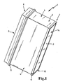
- FIG. 1 shows a filter element 1 with a raw-side upstream side 2 and a clean-side downstream side 3.
- the filter element is formed by a multi-folded filter medium 14, wherein the folds between the upstream side and the downstream side, ie there are each pleat tips on the upstream side and the downstream side ,
- the non-perfused side surfaces of the filter element 4 are surrounded by a polyester fleece, which is provided on its side facing the filter element with a hot melt adhesive layer.
- This hot melt adhesive layer produces a surface bonding of the polyester fleece to the filter element, the front side 5 of the filter bellows also being sealed off.
- the filter element 1 comprises a main frame 6 and an auxiliary frame 7, wherein the main frame carries an axial seal 8, which seals in the direction of the downstream side 3 and is introduced into a groove of the main frame or in a groove between the main frame and side surfaces 4.
- the subframe is connected to the side surfaces 4 by an adhesive connection and has radial surfaces 9 and axial surfaces 10 for supporting the filter element in a housing, not shown.
- FIG. 2 shows an embodiment of a filter element 1 with a raw-side inflow 2 and a clean-side outflow 3.
- a plastic frame 16 is applied by means of a hot melt adhesive, wherein on the end faces 5 by the hot melt adhesive and the sealing of the front side takes place.
- Plastic frame 16 carries on the upstream side 2, an axial seal 12, which is engageable with a sealing surface of a housing, not shown.
- a handle 13 is provided, which is in communication with the plastic frame 16 and for better handling of the filter element 1 is used.
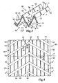
- FIG. 3 shows the detailed view of an arrangement of traces of adhesive on a filter element according to the invention.
- adhesive traces 101 of hotmelt adhesive are introduced into the folds, which extend between fold tips 102 and fold bottom 103.
- 105 adhesive traces 101 are introduced both on the clean side 104 and on the raw side.
- At least two adhesive traces 101 are applied to the filter medium 106 parallel to one another and perpendicular to the direction of the fold edges 102, 103 before the individual folds are set up.
- the traces of adhesive 101 are not continuous, but interrupted at regular intervals by a break 107. On the raw side 105, the adhesive trace is once interrupted between fold tip and wrinkle bottom.
- the interruption 107 is located centrally between the fold tip and wrinkle bottom and corresponds in length between one third and half of the fold height.
- the interruption 107 begins at a distance b from the raw-side fold bottom 103.
- the wrinkles are bonded on the raw side only in the area of the fold bottom and the fold tips.
- an interruption of the adhesive trace over a length a is provided, which surrounds the raw-side fold tip.
- the wrinkles are not glued on the raw side in the area of the pleat tips.
- the distances a and b of roh wornem wrinkle bottom and pure-side pleat tip are formed so that the interruption 107 of the clean side and the raw side adhesive track do not overlap. This ensures that an overlap of the clean-side 104 and raw-side 105 adhesive trace 101 is formed both in the region of the pure-side pleat tips and in the vicinity of the purely-sided pleat base.
- the straight lines x and y formed by the start and end points of the individual adhesive trace portions are parallel to the fold edges.
- FIG. 4 shows an alternative arrangement of adhesive traces on a filter element according to the invention.
- the start and end points of the interruptions of the adhesive tracks 101 are aligned on a plurality of straight lines z, which run parallel to each other and with the folding edges F form an angle ⁇ of 10-80 °, preferably 45 +/- 15 °.
- the beginning and end points of the interruptions of the adhesive tracks run on at least two pairs of straight lines z 'and z'', each straight line comprising mutually parallel straight lines, wherein the corresponding straight lines intersect on the filter medium, whereby an arrow-shaped or zigzag-shaped course of the interruptions 107 of Adhesive trace 101 is formed on the filter medium.
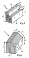
- FIG. 5 1 shows an embodiment of the outer shape of a filter element 1 according to the invention.
- the filter element has at least two sections (301, 302) in which the surfaces 303 and 304 formed by the tube-side pleat tips are parallel but at different distances H (H ', H '') to the respective opposite surface 305.
- the difference in the pleat height of the at least two sections results in a stepped element which allows better space utilization in complex shaped building spaces.
- FIG. 6 shows an embodiment of the outer shape of a filter element according to the invention 1.
- FIG. 7 shows an embodiment of a raw-side pleat tip of a filter according to the invention.
- the pleat tips have a multi-stage shape, wherein in a first region Z, starting from the folded edge, the two filter medium sections enclose an angle ⁇ which is less than 5 °.
- the first area extends over a length Z of about 5mm.
- the opposite filter medium sections enclose an angle ⁇ of about 24 °.
- the opposing filter medium sections extend substantially parallel and include a compared to the above-mentioned angles a negative angle of about 0.2 °, whereby the pure-side distance of the two filter medium sections in the further course along the flow direction ⁇ is smaller.
- the cross section of the raw-side intermediate spaces adjoining on both sides on the right and on the left of this fold increases in the direction of the through-flow direction ⁇ .
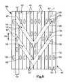
- FIG. 8 a section of a filter medium 106 is shown, which is to the filter media 106 from the FIG. 3 is similar and in filter elements for filters similar to the filter elements 1 from FIGS. 1 . 2 . 5 and 6 Use finds.
- FIG. 8 shows the raw side 105 of a medium portion 120 of the filter medium 106, which extends between two fold edges F.
- the folded edges F are embossed in unfolded filter medium 106 as fold lines.
- the pleat tips 102 surround the fold edges F.
- a plurality of elongated adhesive portions 122 extend along straight traces of adhesive 101.
- the adhesive tracks 101 are equidistant from each other and perpendicular to the fold edges F.
- a distance 132 between two adjacent adhesive tracks 101 is about 25 mm each.
- two equal-length adhesive breaks 107 are arranged between the adhesive sections 122.
- the extent 134 of the adhesive breaks 107 perpendicular to the folded edges F is about 15 mm in each case.
- the adhesive interruptions 107 of adjacent traces of adhesive 101 are arranged offset in the direction of the folded edges F.
- Adhesive portions 122 of adjacent adhesive tracks 101 each delimit a channel portion 124 of a channel located in the untreated fold space 148a of the pleated filter media 106, similar to one associated with FIG FIG. 19 explained below embodiment, extends between the folding edges F.
- the adhesive breaks 107 connect the adjacent channel parts 124.
- the adhesive breaks 107 of the adjacent adhesive tracks 101 realize two passages 126, which in the in the FIG. 8 shown embodiment parallel to the V-shape and each extending obliquely to the folding edges F to each other.
- the passages 126 are in FIG. 8 defined by two V-shaped dashed lines indicated in the form of imaginary lines 128.
- the straight lines 128 are similar to the straight lines z 'and z "according to the exemplary embodiment FIG. 4 , The straight lines 128 extend through the corresponding end points of the adhesive sections 122 Arrangement of the adhesive breaks 107 prevents the passages 126 to extend continuously parallel to the fold edges F.
- FIG. 8 are exemplary risk areas 130 of the filter medium 106, in which this could collapse during operation of the filter without the use of the adhesive portions 122 according to the invention shown with the adhesive breaks 107, for example due to negative pressure, indicated as ellipses.
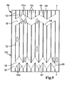
- FIG. 9 a further embodiment of a filter medium 106 is shown, which is the embodiment of FIG. 8 is similar.
- the adhesive breaks 107 arranged so that the in FIG. 9
- the passage 126 shown above extends in a zigzag pattern, wherein the flanks 126a each extend over three adjacent traces of adhesive 101.
- Passage 126 shown below is also zigzag. However, here the flanks 126a each extend over two adjacent adhesive tracks 101. The use of two differently extending passages 126 improves the stability of the filter medium 106.
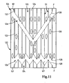
- FIG. 10 Another embodiment of a filter medium 106 according to FIG. 10 is similar to the filter medium 106 of the embodiments according to FIGS FIGS. 8 and 9 , In this embodiment is in the FIG. 10 shown above, a passage 126 in the form of an inverted "V" similar to the "V" in the embodiment FIG. 8 and below a passage 126 with a zigzag course as in the embodiment FIG. 9 realized.
- FIG. 11 A further embodiment according to FIG. 11 is similar to the embodiment of the FIG. 10 constructed here, wherein here the passage 126 shown in the figure above as in the embodiment of FIG. 8 is oriented as "V".
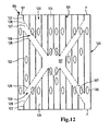
- FIG. 12 In a further embodiment of a filter medium 106 according to FIG. 12 , which for the embodiments of the FIGS. 8 to 11 Similarly, one in the FIG. 12 Upper passage 126 in the form of a "W" on. An Indian FIG. 12 Passage 126 shown below has the shape of an inverted "W".
- the passages 126 as used in the exemplary embodiments in FIGS. 8 to 12 can also be combined in other ways. Thus, more or fewer than two passages 126 may be provided between two fold edges F.
- the adhesive breaks 107 may have identical or different extensions along the adhesive tracks 101 and / or with the different adhesive tracks 101 134 have.
- the extensions 134 may also be smaller or larger than 20 mm. Also, the distances 132 of the adhesive tracks 101 may be different, even smaller or larger than 25 mm.
- clean sides of the medium sections 120 may also be arranged adhesive portions and adhesive interruption along traces of adhesive. These can preferably be arranged so that the adhesive portions 122 on the raw side 105 each project beyond the adhesive interruptions on the clean side on both sides and overlap the adjacent clean-side adhesive interruption adhesive portions at the ends. Conversely, according to the adhesive sections on the clean side, the adhesive breaks 107 on the raw side 105 project beyond.
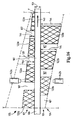
- FIG. 13 a section of a filter element 1 is shown, which is to the filter elements 1 from FIGS. 1 . 2 . 5 and 6 is similar.
- two medium sections 120 are shown extending on both sides from one of the tube-side folding tips 102a.
- a plurality of adhesive portions 122 and adhesive breaks 107 are disposed along equidistant adhesive traces 101.
- the adhesive tracks 101 extend perpendicular to the folded edges F.
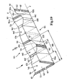
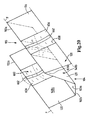
- FIG. 16 is a medium portion 120 of the filter medium 106, which is to the filter media 14; 106 off FIGS. 1 to 15 similar, shown in unfolded condition.
- the filter medium 106 is moved horizontally in a transport direction 140 between an upper application nozzle 142a and a lower application nozzle 142b.
- the raw side 105 of the filter medium is in the FIG. 16 above, the clean side 104 below.
- the adhesive portions 122a on the raw side 105 and the adhesive portions 122b on the clean side 104 of the filter medium 106 are applied.
- the extension 144 of the adhesive portions 122 perpendicular to the filter medium 106 from the front in the transport direction 140 takes Folding edge F, in FIG. 16 on the right, to the rear folding edge F, left, both within an adhesive portion 122a and between the adhesive portions 122a, which are separated by adhesive breaks 107 from each other towards continuously.
- the extension 144 of the adhesive portions 122 b therefrom continuously decreases from the front fold edge F to the rear fold edge F.
- the raw-side adhesive portions 122a overlap with the clean-side adhesive portions 122b so that each of the raw-side adhesive portions 122a projects beyond the clean-side adhesive breaks 107, and conversely, the clean-side adhesive portions 122b overhang the raw-side adhesive breaks 107.
- medium portion which follows the shown medium portion 120 in the transport direction 140, take the expansions 144 of the raw-side adhesive portions 122a from the rear in the transport direction 140 folding edge F to the next following folding edge down. Accordingly, on the clean side 104 in the next medium section, the extent 144 of the adhesive sections 122b increases from the rear fold edge F to the next following fold edge. Analog is also in FIG. 16 not shown, the media portion shown 120 in the transport direction 140 preceding medium section with respect to the front fold edge F mirror-symmetrical to the medium section 120 shown constructed.
- FIG. 17 a filter element 1 is shown in longitudinal section, which from a to the filter medium 106 from FIG. 16 similar filter element 106 is folded.
- the raw-side wrinkle interstices 148 a the free sides of the raw-side adhesive portions 122 a of a medium portion 120 facing away from the surface of the filter medium 106 abut against the respective free sides of the adhesive portions 122 a of the respective opposite medium portion 120.
- the adjoining adhesive portions 122a adjacent medium portions 120 of a folding gap 148 are supported against each other and held in shape.
- the adhesive portions 122 define boundaries for the channel sections 124 that are in FIGS. 3, 4 and 8 to 15 are shown.
- FIG. 18 is a section of a further embodiment of a filter element 1 shown, in which the raw-side pleat tips 102a similar to the embodiment of FIG. 7 are multi-level shaped.
- the total fold height 550 is about 5 cm to 40 cm, especially 20 cm to 40 cm.
- the thickness 151 of the filter medium 106 is about 0.5 mm.
- the filter medium sections 120 which extend on both sides of the raw-side pleat tips 102a to the adjacent unfolded pleat bottoms 103a, each have at the end of a first region 120a at a distance Z from the folded edge F a first bend 552 toward the raw side 105.
- the extension Z of the first region 120a is about 5 mm.
- the first regions 120a include an angle ⁇ of about 5 °. You can instead include an angle ⁇ of less than 5 ° or between 5 ° and about 10 °.
- the filter medium sections 120 have a second bend 554 toward the clean side 104.
- the extent ⁇ of a second region 120b between the first bend 552 and the second bend 554 is about 5 mm.
- the second regions 120b include an angle ⁇ of about 24 °. You can instead include an angle ⁇ between 10 ° and 24 ° or between 24 ° and 40 °.
- the expansions ⁇ and / or Z can also be less than 5 mm or up to about 10 mm.
- respective third regions 120c extend as far as the crude-side fold bases 103a.
- the third regions 120c enclose an angle of about 0.2 °. You may instead include another angle preferably between about -5 ° and about + 5 °.
- the sheet-side folding bases 103a have a roughly V-shaped profile that tapers to the respective raw-side folded edge 102a.
- the pure-side Faltrich 1 03b have an approximately U-shaped profile.
- Clean-side filter base widths 556 of the clean-side filter bases 103b at the height of the two second bends 554 at a distance 560 from the corresponding raw-side fold edge 102a are smaller than raw-side filter base widths 558 of the raw-side filter bases 103a at the corresponding distance 560 from the clean-side fold edges 102b.
- the shape of the raw-side folding tips 102a is formed in the production in that the filter medium 106 is first folded along the folded edges F and then crimped in the first regions 120a. In this case, the material of the filter medium 106 is compressed in the first region 120a and at the same time the first bends 552 and the second bends 554 are formed.
- adhesive sections 122 and adhesive breaks 107 along corresponding traces of adhesive 101 may be arranged.
- the medium portions 120 are similar to those shown below FIGS. 19 to 25 described embodiments, on the clean side 105 depressions 656, which realize on the raw pages 104 corresponding elevations 658.
- FIG. 19 a section of a filter element 1 according to a further embodiment is shown.
- the filter medium 106 is embossed into a plurality of elongate depressions 656.
- the depressions 656 extend perpendicularly to the fold edges F between the raw-side fold tips 102a and the raw-side fold bases 103a.
- the depressions 656 each have a depth 664a of approximately 1 mm.
- a width 666 of the depressions 656 in the direction of the folded edges F is about 25 mm to 35 mm.
- the depth 664 of the valleys 656 is as in FIG FIG. 21 shown in cross section, about the height of the folds substantially constant.
- the depths 664b of the depressions 656b are removed from the raw-side pleat tips 102a toward the unilateral folding bases 103a.
- each left-hand wrinkles are exemplified by the raw-side pleat tips 102a similar to the embodiments FIGS. 7 and 18 squeezed and graded several times.
- the depressions 656 are realized as groovings which form corresponding elevations 658 on the clean side 104.
- the depressions 656 of the two medium sections 120, which delimit the fold gap 148a lie directly opposite one another and each form a flow channel 660.
- the flow channels 660 extend perpendicular to the fold edges F.
- right depressions 656 is exemplified in each case a support back 662 formed in the medium portions 120.
- the support back 662 rise to the clean side 104 back.
- a glue bead 622 are each arranged by way of example instead of the support back 262 on the clean side 104.
- the glue beads 622 serve to stabilize the flow channel 660.
- the support backs 662 may also be combined with the glue beads 622, for example, such that the glue beads 622 are on the support back 662.
- an adhesive section 122 with adhesive breaks 107 is disposed on the raw side 105.
- These adhesive portions 122 extend similar to the embodiments FIGS. 3, 4 and 8 to 18 along adhesive traces 101.
- FIG. 20 a further embodiment of a filter element 1 is shown, which to the filter element 1 from FIG. 19 is similar.
- the raw-side fold bases 103a in the embodiment in FIG. 20 widened in comparison to the pure-sided fold reasons 103b.
- the wrinkle spaces 148a and 148b have a similar effect as the folding spaces 148a and 148b of the filter element 1 from FIG. 18 ,
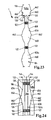
- FIG. 23 is a section of the filter element 1 from FIG. 19 shown parallel to a plane through the raw-side pleat tips 102a.
- the adhesive sections 122 of the opposite medium sections 120 are similar, similar to the exemplary embodiment FIG. 17 , flat against each other and thus limit the flow channels 660.
- FIG. 24 is a filter element 1, which is similar to the filter element 1 from FIG. 20 also shown in a section parallel to a plane through the raw-side pleat tips 102a.
- the support back 662 of the medium sections 120 abut each other and thus stabilize the folds and the filter element 1.
- adhesive sections 122 are provided with adhesive breaks 107.
- the extensions 144 of the adhesive portions 122 perpendicular to the respective bare-side surfaces of the filter media 106 in the embodiments vary from FIGS FIGS. 23 and 24 analogous to the embodiments of Figures 16 and 17 , so that the adhesive portions 122 lie flat against each other and support each other.
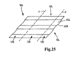
- FIG. 25 an unfolded filter medium 106 is shown, which with grooves for the realization of the depressions 656 and the elevations 658 according to the embodiments of FIGS. 19 to 24 is provided.
- the groovings run perpendicular to the folded edges F.
- the elevations 658 and depressions 656 can also be realized by grooving, which are interrupted at the folded edges F.
- the straight adhesive traces 101 may instead of perpendicular also obliquely or partially obliquely to the folded edges F.
- the adhesive portions 122 and the adhesive breaks 107 may take place along the straight traces of adhesive 101 also along different adhesive traces, for. As winding or meandering traces of adhesive can be arranged.
- the passages 126 can also run in other ways, at least in sections, not parallel to the folded edges F.
- every second medium section may be free of adhesive portions.
- the extension 144 of the adhesive portions 122 on the other media portions 120 may extend across the entire interleaf space in that case.
- the free sides of the adhesive portions 192 are then flat against the respective opposite, not provided with adhesive portions surface of the local medium portion 120 at.
- FIGS. 26-34 show by way of example some embodiments of filter media, which can be used in addition to other filter media for a filter according to the invention.
- FIG. 26 shows an uncoated PA 6.6 grid with a mesh size of 100 ⁇ 10 ⁇ m
- FIG. 27 such a grid with a coating of nanofibers
- FIG. 28 shows the coated grid in cross section.
- the air permeability of the uncoated lattice is ⁇ 10,000 l / (m2s), that of the coated lattice is ⁇ 800-1,500 l / (m2s).
- the screen fineness is 69.9 n / cm, the thickness 70 ⁇ m and the basis weight 24 g / cm 2.
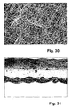
- a PA 6.6 grid is shown which has a mesh size of 102 ⁇ 6 ⁇ m.
- FIG. 30 shows the coated grid and FIG. 31 a cross-sectional view of the coated grid.
- the air permeability of the uncoated grid is ⁇ 8,600 l / (m2s), that of the coated grid is ⁇ 1,500 l / (m2s).
- the sieving fineness is 65 n / cm, the thickness 80 microns and the basis weight 35 g / cm2.
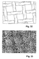
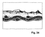
- Another PA 6.6 lattice is in the FIG. 32 to 34 shown.
- the mesh size is 150 ⁇ 9 ⁇ m.
- the air permeability of the uncoated lattice is ⁇ 11,000 l / (m2s), that of the coated lattice is ⁇ 650-840 l / (m2s).
- the screen fineness is 47 n / cm, the thickness 95 ⁇ m and the basis weight 35 g / cm 2.
- FIG. 32 shows the uncoated grid
- FIG. 33 the coated grid
- FIG. 34 the coated grid in cross section.
Landscapes
- Chemical & Material Sciences (AREA)
- Chemical Kinetics & Catalysis (AREA)
- Engineering & Computer Science (AREA)
- Combustion & Propulsion (AREA)
- Filtering Of Dispersed Particles In Gases (AREA)
- Filtering Materials (AREA)
- Separating Particles In Gases By Inertia (AREA)
Claims (11)
- Élément filtrant pour un filtre, conçu pour le filtrage de fluides, notamment de gaz, notamment d'air d'aspiration, de carburant, de solution d'urée ou d'huile de moteur, notamment d'un moteur à combustion interne notamment d'un véhicule automobile, ou d'air ambiant destiné à être introduit dans des systèmes de ventilation de bâtiments ou de véhicules, l'élément filtrant (1) présentant un milieu filtrant (14 ; 106) plié en accordéon avec un côté brut (105) et un côté pur (104), plusieurs sections longitudinales de colle (122) étant disposées, du côté brut (105) et/ou du côté pur (104) du milieu filtrant (14 ; 106), sur le milieu filtrant (14 ; 106) le long d'au moins deux cordons de colle (101), ces sections s'étendant au moins en partie à l'oblique ou à la verticale d'arêtes de pliage (F), au moins une section de colle (122) et au moins une interruption de colle (107) étant disposées sur chaque cordon de colle (101), caractérisé en ce que les interruptions de colle (107) des différents cordons de colle (101) sont décalées les unes par rapport aux autres, considéré en direction des arêtes de pliage (F), de sorte qu'en raison de ces interruptions de colle (107) dans une zone du milieu (120) qui s'étend entre deux arêtes de pliage voisines (F), il n'y ait pas de passage (126) continuellement parallèle aux arêtes de pliage.
- Élément filtrant selon la revendication 1, caractérisé en ce que le passage (126) est exécuté en accordéon, notamment en V ou en W.
- Élément filtrant selon la revendication 1 ou 2, caractérisé en ce que les cordons de colle sont des lignes droites de colle (101) qui sont parallèles les unes aux autres et verticales par rapport aux arêtes de pliage (F).
- Élément filtrant selon la revendication 3, caractérisé en ce que les cordons de colle (101) sont équidistants.
- Élément filtrant selon la revendication 3, caractérisé en ce que les espaces (132a, 132b, 132c, 132d) entre les cordons de colle (101) voisins, considéré en direction des arêtes de pliage (F), croissent ou décroissent d'une face frontale (136a) de l'élément filtrant (1) à l'autre face frontale (136b).
- Élément filtrant selon la revendication 3, caractérisé en ce que les espaces (132e, 132f, 132g) entre les cordons de colle (101) voisins, considéré par rapport à un plan de symétrie (138) vertical aux arêtes de pliage (F), de préférence central par rapport à l'ampleur du milieu filtrant (14 ; 106) en direction des arêtes de pliage (F), croissent, notamment vers l'extérieur.
- Élément filtrant selon l'une des revendications précédentes, caractérisé en ce que, du côté brut (105) et du côté pur (104), des sections de colle (122) sont disposées de manière à ce qu'au moins l'une des sections de colle (122) du côté brut (105) dépasse des deux côtés au moins de l'une des interruptions de colle (107) du côté pur (104) et chevauche, avec ses extrémités, les sections de colle (122) du côté pur (104) qui sont adjacentes à l'interruption de colle (107), et/ou qu'au moins une des sections de colle (122) du côté pur (104) dépasse des deux côtés au moins de l'une des interruptions de colle (107) du côté brut (105) et chevauche, avec ses extrémités, les sections de colle (122) du côté brut (105) qui sont adjacentes à l'interruption de colle (107).
- Élément filtrant selon l'une des revendications précédentes, caractérisé en ce que l'ampleur (144) des sections de colle (122) à la verticale du milieu filtrant (14 ; 106) le long d'un cordon de colle (101) varie de sorte que, sur le milieu filtrant (14 ; 106) plié, les sections de colle (122) soient appliquées sur toute leur surface, avec leur face libre opposée au milieu filtrant (14 ; 106), sur une face libre correspondante d'une section de colle opposée (122) dans un interstice de pliage (148a, 148b) ou sur la surface de la section du milieu (120) opposée dans l'interstice de pliage (148a,148b).
- Élément filtrant selon l'une des revendications précédentes, caractérisé en ce que des sections de milieu filtrant (120) qui s'étendent des deux côtés entre des crêtes de plis (1 02a) du côté brut et les creux de plis (103a) voisins du côté brut, considéré respectivement des crêtes de plis (1 02a) du côté brut, présentent une première courbure (552) vers le côté brut (105) et, derrière cette première courbure, une deuxième courbure (554) vers le côté pur (104).
- Élément filtrant selon l'une des revendications précédentes, caractérisé en ce que, du côté brut (105), plusieurs cavités longitudinales (656) sont formées dans le milieu filtrant (14 ; 106), lesquelles s'étendent entre des crêtes de plis (102a) du côté brut et des creux de plis (103a) du côté brut à peu près à la verticale des arêtes de pliage (F) du milieu filtrant (14 ; 106) et forment du côté pur (104) des éminences (658) correspondantes de sorte que, dans un interstice de pliage (148a) du côté brut, respectivement deux cavités (656) se font directement face sur les deux sections de milieu (120) limitant l'interstice de pliage (148a) et forment respectivement un canal d'écoulement (660).
- Filtre conçu pour le filtrage de fluides, notamment de gaz, notamment d'air d'aspiration, de carburant, de solution d'urée ou d'huile de moteur, notamment d'un moteur à combustion interne notamment d'un véhicule automobile, ou d'air ambiant destiné à être introduit dans des systèmes de ventilation de bâtiments ou de véhicules, avec un élément filtrant (1) selon l'une des revendications précédentes.
Applications Claiming Priority (2)
| Application Number | Priority Date | Filing Date | Title |
|---|---|---|---|
| DE102009040202.0A DE102009040202B4 (de) | 2009-09-07 | 2009-09-07 | Filter |
| PCT/EP2010/063131 WO2011026999A1 (fr) | 2009-09-07 | 2010-09-07 | Filtre destiné à la filtration de fluides |
Publications (2)
| Publication Number | Publication Date |
|---|---|
| EP2475449A1 EP2475449A1 (fr) | 2012-07-18 |
| EP2475449B1 true EP2475449B1 (fr) | 2013-11-06 |
Family
ID=42942226
Family Applications (3)
| Application Number | Title | Priority Date | Filing Date |
|---|---|---|---|
| EP10754454.6A Revoked EP2477718B1 (fr) | 2009-09-07 | 2010-09-07 | Element de filtration et filtre pour la filtration des fluides |
| EP10754309.2A Active EP2475450B1 (fr) | 2009-09-07 | 2010-09-07 | Filtre pour la filtration des fluids et procede de fabircation d'un tel filtre |
| EP10754308.4A Active EP2475449B1 (fr) | 2009-09-07 | 2010-09-07 | Element de filtration et filtre pour la filtration des fluides |
Family Applications Before (2)
| Application Number | Title | Priority Date | Filing Date |
|---|---|---|---|
| EP10754454.6A Revoked EP2477718B1 (fr) | 2009-09-07 | 2010-09-07 | Element de filtration et filtre pour la filtration des fluides |
| EP10754309.2A Active EP2475450B1 (fr) | 2009-09-07 | 2010-09-07 | Filtre pour la filtration des fluids et procede de fabircation d'un tel filtre |
Country Status (10)
| Country | Link |
|---|---|
| US (4) | US8746462B2 (fr) |
| EP (3) | EP2477718B1 (fr) |
| JP (1) | JP5898075B2 (fr) |
| KR (1) | KR101865418B1 (fr) |
| CN (2) | CN102612397B (fr) |
| BR (2) | BR112012005045B1 (fr) |
| DE (1) | DE102009040202B4 (fr) |
| MX (1) | MX2012002820A (fr) |
| RU (1) | RU2548413C2 (fr) |
| WO (3) | WO2011027000A1 (fr) |
Families Citing this family (74)
| Publication number | Priority date | Publication date | Assignee | Title |
|---|---|---|---|---|
| KR20060127066A (ko) | 2003-12-22 | 2006-12-11 | 도날드슨 캄파니 인코포레이티드 | 시일 구성을 구비하는 필터요소 및 그 제조 방법 |
| US8409316B2 (en) | 2005-11-09 | 2013-04-02 | Donaldson Company, Inc. | Seal arrangement for filter element; filter element assembly; and, methods |
| DE102006014236A1 (de) | 2006-03-28 | 2007-10-04 | Irema-Filter Gmbh | Plissierbares Vliesmaterial und Verfahren und Vorrichtung zur Herstellung derselben |
| EP2190554B1 (fr) | 2007-09-07 | 2013-01-09 | Donaldson Company, Inc. | Ensemble filtre à air |
| PL2304326T3 (pl) * | 2008-01-14 | 2019-05-31 | Core Energy Recovery Solutions Inc | Membranowe wkłady harmonijkowe-krzyżowe i sposób wytwarzania membranowych wkładów harmonijkowych-krzyżowych |
| JP5466853B2 (ja) * | 2008-12-25 | 2014-04-09 | 日本無機株式会社 | プリーツ型エアフィルタパック及びそれを用いたエアフィルタ |
| US8061530B2 (en) | 2009-04-09 | 2011-11-22 | Cummins Filtration Ip, Inc. | Filtration sealing system |
| DE102014009886B4 (de) * | 2014-07-04 | 2026-05-13 | Mann+Hummel Gmbh | Filterelement zur Filtrierung von Medien |
| DE102012005532A1 (de) | 2012-03-21 | 2013-09-26 | Mann + Hummel Gmbh | Filterelement eines Filters zur Filtrierung von Fluiden und Filter |
| EP2563494A4 (fr) * | 2010-04-30 | 2013-12-18 | Diversitech Corp | Filtre tridimensionnel |
| DE102010032295A1 (de) * | 2010-07-26 | 2012-01-26 | Mann + Hummel Gmbh | Filterelement und Verfahren zur Herstellung eines Filterelements |
| DE102010052155A1 (de) * | 2010-11-22 | 2012-05-24 | Irema-Filter Gmbh | Luftfiltermedium mit zwei Wirkmechanismen |
| DE102011013921A1 (de) * | 2011-03-14 | 2012-09-20 | Mann + Hummel Gmbh | Filterelement-Kassette |
| DE102012000490A1 (de) * | 2012-01-13 | 2013-07-18 | Mann + Hummel Gmbh | Luftfilterelement und Luftfilter |
| DE102012000470A1 (de) * | 2012-01-13 | 2013-07-18 | Mann + Hummel Gmbh | Luftfilterelement und Luftfilter |
| EP2806962B1 (fr) * | 2012-01-26 | 2016-03-30 | Mann + Hummel Gmbh | Élément filtrant et procédé de fabrication d'un élément filtrant |
| US10058808B2 (en) * | 2012-10-22 | 2018-08-28 | Cummins Filtration Ip, Inc. | Composite filter media utilizing bicomponent fibers |
| PL2742986T3 (pl) * | 2012-12-17 | 2018-10-31 | Mann + Hummel Gmbh | Układ filtra powietrza, element filtra powietrza i sposób wymiany elementu filtra powietrza |
| US10040018B2 (en) | 2013-01-09 | 2018-08-07 | Imagine Tf, Llc | Fluid filters and methods of use |
| DE102013008402B4 (de) | 2013-05-16 | 2025-07-17 | Irema-Filter Gmbh | Faservlies und Verfahren zur Herstellung desselben |
| DE102013011086A1 (de) | 2013-07-03 | 2015-01-08 | Mann + Hummel Gmbh | Filterelement und Verfahren zur Herstellung eines Filterelements |
| DE102014009026A1 (de) * | 2013-07-12 | 2015-01-15 | Mann + Hummel Gmbh | Filterelement mit wenigstens einem Führungssteg, Filter mit einem Filterelement und Filtergehäuse eines Filters |
| JP6352076B2 (ja) * | 2013-07-12 | 2018-07-04 | マン ウント フンメル ゲゼルシャフト ミット ベシュレンクテル ハフツング | ハンドグリップエレメントを有するフィルタエレメント及びフィルタエレメントを有するフィルタ |
| CN103446836B (zh) * | 2013-09-13 | 2015-08-19 | 长春天勤环境工程有限公司 | W形预收尘装置 |
| US9861920B1 (en) | 2015-05-01 | 2018-01-09 | Imagine Tf, Llc | Three dimensional nanometer filters and methods of use |
| US9233332B2 (en) | 2014-06-02 | 2016-01-12 | Caterpillar Inc. | Air filter assembly filling plenum interior space |
| US10730047B2 (en) | 2014-06-24 | 2020-08-04 | Imagine Tf, Llc | Micro-channel fluid filters and methods of use |
| JP6619419B2 (ja) | 2014-08-01 | 2019-12-11 | ドナルドソン カンパニー,インコーポレイティド | ろ材、プリーツ状媒介材料パック、フィルタカートリッジ、および作製方法 |
| US10124275B2 (en) | 2014-09-05 | 2018-11-13 | Imagine Tf, Llc | Microstructure separation filters |
| CA2960497C (fr) * | 2014-09-08 | 2023-10-10 | Clarcor Air Filtration Products, Inc. | Filtre a grande capacite d'empoussierage |
| BR112017007297B1 (pt) | 2014-10-10 | 2022-02-01 | Baldwin Filters, Inc | Método para proporcionar reforço de um pacote de meio de filtragem |
| US9752541B2 (en) | 2014-12-05 | 2017-09-05 | Caterpillar Inc. | Filter media |
| US10758849B2 (en) | 2015-02-18 | 2020-09-01 | Imagine Tf, Llc | Three dimensional filter devices and apparatuses |
| DE102016005157A1 (de) | 2015-05-22 | 2016-11-24 | Mann + Hummel Gmbh | Filtereinsatz für ein Fluid, insbesondere Getriebeöl |
| ITUB201543363U1 (it) * | 2015-06-03 | 2016-12-03 | Officine Metallurgiche G Cornaglia S P A | Cartuccia filtro aria a pannello compatta ad elevata efficienza per motori endotermici. |
| US10118842B2 (en) | 2015-07-09 | 2018-11-06 | Imagine Tf, Llc | Deionizing fluid filter devices and methods of use |
| US10479046B2 (en) | 2015-08-19 | 2019-11-19 | Imagine Tf, Llc | Absorbent microstructure arrays and methods of use |
| US11020698B2 (en) | 2015-12-11 | 2021-06-01 | Cummins Filtration Ip, Inc. | Filter with variable cross-section axial seal |
| AU2017217863B2 (en) | 2016-02-12 | 2022-09-29 | Donaldson Company, Inc. | Filter elements, air cleaner assemblies, and methods of use and assembly |
| US11167234B2 (en) | 2016-03-18 | 2021-11-09 | Cummins Filtration Ip, Inc. | Interlocked stable filter assembly |
| MX2018013103A (es) * | 2016-05-02 | 2019-03-28 | Cummins Filtration Ip Inc | Filtro con interfaz de alojamiento de enclavamiento. |
| CN109641167B (zh) * | 2016-08-29 | 2021-05-25 | Emd密理博公司 | 用于压紧式褶皱构型过滤件的固定刚性壁装置 |
| WO2018102712A2 (fr) | 2016-12-01 | 2018-06-07 | Donaldson Company, Inc. | Éléments filtrants, ensembles de filtres à air et procédés d'utilisation et d'assemblage |
| US10357731B2 (en) * | 2016-12-20 | 2019-07-23 | Baldwin Filters, Inc. | Filter with preformed end caps having notch feature |
| WO2018140310A1 (fr) | 2017-01-25 | 2018-08-02 | Cummins Filtration Ip, Inc. | Adaptateur fileté extensible pour enveloppe sans filetage |
| RU171762U1 (ru) * | 2017-01-27 | 2017-06-15 | Федеральное государственное бюджетное образовательное учреждение высшего образования "Волгоградский государственный технический университет" (ВолгГТУ) | Фильтрующий элемент |
| US11724220B2 (en) | 2017-02-21 | 2023-08-15 | Cummins Filtration Ip, Inc. | Undulated interlocking housing-endplate interface geometry |
| CN115155166B (zh) | 2017-03-16 | 2024-01-26 | 康明斯滤清系统知识产权公司 | 过滤密封系统 |
| US11364462B2 (en) | 2017-09-25 | 2022-06-21 | Donaldson Company, Inc. | Filter assembly |
| AR113747A1 (es) * | 2017-10-06 | 2020-06-10 | Candu Energy Inc | Método y aparato para filtrar fluidos en la generación de energía nuclear |
| CN107715547A (zh) * | 2017-10-31 | 2018-02-23 | 无锡德沃精工设备有限公司 | 一种过滤效果好的超精油过滤设备 |
| JP2019108802A (ja) * | 2017-12-15 | 2019-07-04 | 株式会社マーレ フィルターシステムズ | エアクリーナ |
| CN112020387A (zh) | 2018-01-24 | 2020-12-01 | 唐纳森公司 | 过滤器元件、系统和方法 |
| CN112469487A (zh) | 2018-07-23 | 2021-03-09 | 康明斯滤清系统公司 | 用于旋装式过滤器的径向密封 |
| US10632402B1 (en) * | 2018-10-24 | 2020-04-28 | Pall Corporation | Support and drainage material, filter, and method of use |
| DE102018130552A1 (de) * | 2018-11-30 | 2020-06-04 | Mann+Hummel Gmbh | Flüssigkeitsfilter |
| EP3921061B1 (fr) | 2019-02-04 | 2025-10-29 | Donaldson Company, Inc. | Elemente filtrant pour la filtration d'un fluid |
| US12083464B2 (en) | 2019-02-08 | 2024-09-10 | Donaldson Company, Inc. | Filter element, air cleaner assembly, and methods |
| EP3946683B1 (fr) | 2019-03-27 | 2023-12-27 | Donaldson Company, Inc. | Filtre séparateur de particules à face d'écoulement s'étendant axialement |
| DE102019115568A1 (de) * | 2019-06-07 | 2020-12-10 | Mann+Hummel Gmbh | Filterelement und Filtersystem |
| US11794142B2 (en) * | 2019-11-05 | 2023-10-24 | Parker-Hannifin Corporation | Pulse cleanable deep pleated industrial filter |
| DE102019132413B4 (de) * | 2019-11-29 | 2022-10-06 | Mann+Hummel Gmbh | Flüssigkeitsfilter zur Filterung von Getriebeöl und dessen Verwendung |
| WO2021163027A1 (fr) | 2020-02-11 | 2021-08-19 | Cummins Filtration Inc. | Système de filtration de carburant avancé avec conception de joint d'étanchéité de cartouche à interverrouillage |
| RU2748917C1 (ru) * | 2020-05-18 | 2021-06-01 | Общество с ограниченной ответственностью "Научно-производственное предприятие "Микросистема" | Способ изготовления воздушного фильтра для помещений с повышенными требованиями к содержанию частиц пыли в воздухе |
| DE102020120248A1 (de) * | 2020-07-31 | 2022-02-03 | Mann+Hummel Gmbh | Filterelement und Verfahren zum Herstellen eines Filterelements |
| DE102020128911A1 (de) | 2020-11-03 | 2022-05-05 | Mann+Hummel Gmbh | Filtersystem und Filterelement |
| KR20230167390A (ko) * | 2021-04-09 | 2023-12-08 | 니혼 무키 가부시키가이샤 | 필터팩 및 그것을 구비하는 에어필터 |
| DE102021126855A1 (de) | 2021-10-15 | 2023-04-20 | Mann+Hummel Gmbh | Filterelement und Filtersystem |
| DE102021126857A1 (de) | 2021-10-15 | 2023-04-20 | Mann+Hummel Gmbh | Filterelement und Filtersystem |
| CN114159911B (zh) * | 2021-12-03 | 2022-11-29 | 徐州鑫源环保设备有限公司 | 一种除尘格栅装置 |
| EP4466085A1 (fr) | 2022-01-18 | 2024-11-27 | Donaldson Company, Inc. | Cartouches filtrantes ; ensembles purificateurs d'air ; boîtier ; caractéristiques ; éléments constitutifs ; et procédés |
| WO2025240907A1 (fr) | 2024-05-17 | 2025-11-20 | Donaldson Company, Inc. | Éléments filtrants et ensembles |
| EP4650029B1 (fr) | 2024-05-17 | 2026-01-28 | Donaldson Company, Inc. | Éléments filtrants et ensembles |
| US12434181B1 (en) | 2024-11-01 | 2025-10-07 | Donaldson Company, Inc. | Air cleaner and filtration assemblies |
Family Cites Families (36)
| Publication number | Priority date | Publication date | Assignee | Title |
|---|---|---|---|---|
| GB880812A (en) * | 1958-01-15 | 1961-10-25 | Gen Motors Ltd | Improvements in or relating to filters for fluids |
| DE1299230B (de) * | 1966-12-24 | 1969-07-10 | Draegerwerk Ag | Verfahren zum Herstellen eines Schwebstoffiltereinsatzes aus gefaltetem Filtermaterial fuer Schwebstoffilter von Atemschutzgeraeten |
| US3531920A (en) * | 1968-09-16 | 1970-10-06 | Cambridge Filter Corp | Filter |
| US3871851A (en) * | 1972-07-27 | 1975-03-18 | Delbag Luftfilter Gmbh | Filter pack |
| US4177050A (en) * | 1976-08-23 | 1979-12-04 | Farr Company | Air filter assembly |
| DE3037019C2 (de) * | 1980-10-01 | 1986-01-09 | Drägerwerk AG, 2400 Lübeck | Schwebstoffiltereinsatz aus gefaltetem Schwebstoffiltermaterial für Schwebstoffilter und ein Verfahren zu seiner Herstellung |
| AT368402B (de) * | 1981-05-27 | 1982-10-11 | Walther Peter A Ing | Filter und verfahren zu dessen herstellung |
| JPS60140624U (ja) * | 1984-02-29 | 1985-09-18 | アマノ株式会社 | 集塵機用フイルタのスペ−サ |
| US5236480A (en) * | 1989-01-05 | 1993-08-17 | Camfil Ab | Air filter for workstations and methods of making and using such air filter |
| DE68911665T2 (de) * | 1989-01-05 | 1994-07-07 | Camfil Ab | Filter. |
| GB9112615D0 (en) * | 1991-06-12 | 1991-07-31 | Domnick Hunter Filters Ltd | Filter |
| RU2066232C1 (ru) * | 1992-09-18 | 1996-09-10 | Зеликсон Борис Малкиэлевич | Фильтрующий элемент для фильтра очистки воздуха |
| JP3178491B2 (ja) * | 1993-08-05 | 2001-06-18 | 株式会社泰光 | フィルタ及びその製造方法 |
| DE4328846C2 (de) * | 1993-08-27 | 1999-05-20 | Mann & Hummel Filter | Verfahren zur Herstellung eines Filtereinsatzes und durch dieses Verfahren hergestellter Filtereinsatz |
| DE4345122A1 (de) * | 1993-12-30 | 1995-07-06 | Detroit Holding Ltd | Verfahren zur Herstellung eines Filtereinsatzes |
| IES80929B2 (en) * | 1997-11-26 | 1999-06-30 | Donal Richard Mcgoey | Filter with form-retaining stabilizing means |
| ATE235951T1 (de) * | 1997-12-03 | 2003-04-15 | Jacobi Systemtechnik Gmbh | Filterelement sowie verfahren und klebstoff- auftragvorrichtung zu dessen herstellung |
| SE512385C2 (sv) * | 1998-03-25 | 2000-03-06 | Camfil Ab | Luftfilter av veckat filtermaterial och sätt för dess framställning |
| JP4033973B2 (ja) * | 1998-06-30 | 2008-01-16 | 松下エコシステムズ株式会社 | フィルター |
| JP2000107539A (ja) * | 1998-10-01 | 2000-04-18 | Daikin Ind Ltd | エアフィルターパックおよびエアフィルター |
| US6171354B1 (en) * | 1998-10-13 | 2001-01-09 | S. C. Johnson & Son, Inc. | Self-adhesive air filter for forced air climate control system |
| JP3061135B1 (ja) * | 1999-06-21 | 2000-07-10 | 日立プラント建設株式会社 | クリーンルーム用のエアフィルタ |
| DE10015951C2 (de) * | 1999-12-22 | 2002-09-26 | Jacobi Systemtechnik Gmbh | Filterelement |
| AU761797B2 (en) * | 2000-05-29 | 2003-06-12 | Heru Prasanta Wijaya | Air guided filter for internal combustion engine |
| DE10113077A1 (de) * | 2000-09-21 | 2002-04-25 | Lippold Hans Joachim | Fluidfilterelement |
| JP2002370007A (ja) * | 2001-06-14 | 2002-12-24 | Akushii:Kk | エアフィルタ用ろ材 |
| JP4257613B2 (ja) * | 2002-05-20 | 2009-04-22 | 東洋紡績株式会社 | 成形繊維状シート、及びフィルターユニット |
| CN100520045C (zh) * | 2004-03-31 | 2009-07-29 | 曼·胡默尔有限公司 | 用于汽车内燃机的进气滤清器 |
| JP2006043669A (ja) * | 2004-08-04 | 2006-02-16 | Shinwa Corp | 空調用フィルタ濾材 |
| US7591883B2 (en) * | 2004-09-27 | 2009-09-22 | Cornell Research Foundation, Inc. | Microfiber supported nanofiber membrane |
| JP2008030025A (ja) * | 2006-06-27 | 2008-02-14 | Nitta Ind Corp | フィルタ濾材及びエアフィルタ |
| US20080067121A1 (en) * | 2006-09-15 | 2008-03-20 | Lpd Technologies, Inc. | Fluid filter element with reinforcing scrim |
| DE102007027299B4 (de) * | 2007-06-11 | 2009-02-26 | Johns Manville Europe Gmbh | Filter, Verfahren zu dessen Herstellung, dessen Verwendung sowie Filtermodule |
| EP2227308A2 (fr) * | 2007-11-09 | 2010-09-15 | Hollingsworth & Vose Company | Milieu filtrant soufflé par fusion |
| JP2009195842A (ja) * | 2008-02-22 | 2009-09-03 | Nitta Ind Corp | エアフィルタ及び濾材パック |
| MX2012008542A (es) * | 2010-01-25 | 2012-11-12 | Donaldson Co Inc | Medios de filtracion plisados con estrias conicas. |
-
2009
- 2009-09-07 DE DE102009040202.0A patent/DE102009040202B4/de active Active
-
2010
- 2010-09-07 JP JP2012527356A patent/JP5898075B2/ja not_active Expired - Fee Related
- 2010-09-07 EP EP10754454.6A patent/EP2477718B1/fr not_active Revoked
- 2010-09-07 BR BR112012005045-1A patent/BR112012005045B1/pt active IP Right Grant
- 2010-09-07 CN CN201080051356.8A patent/CN102612397B/zh active Active
- 2010-09-07 WO PCT/EP2010/063132 patent/WO2011027000A1/fr not_active Ceased
- 2010-09-07 EP EP10754309.2A patent/EP2475450B1/fr active Active
- 2010-09-07 MX MX2012002820A patent/MX2012002820A/es active IP Right Grant
- 2010-09-07 BR BR112012005130A patent/BR112012005130A2/pt not_active Application Discontinuation
- 2010-09-07 WO PCT/EP2010/063131 patent/WO2011026999A1/fr not_active Ceased
- 2010-09-07 EP EP10754308.4A patent/EP2475449B1/fr active Active
- 2010-09-07 CN CN201080051359.1A patent/CN102612398B/zh active Active
- 2010-09-07 WO PCT/EP2010/063133 patent/WO2011027001A1/fr not_active Ceased
- 2010-09-07 KR KR1020127005852A patent/KR101865418B1/ko not_active Expired - Fee Related
- 2010-09-07 RU RU2012113550/05A patent/RU2548413C2/ru not_active IP Right Cessation
-
2012
- 2012-03-07 US US13/413,801 patent/US8746462B2/en active Active
- 2012-03-07 US US13/413,763 patent/US8328022B2/en active Active
- 2012-03-07 US US13/413,778 patent/US8479924B2/en active Active
-
2013
- 2013-07-09 US US13/937,461 patent/US20140014572A1/en not_active Abandoned
Also Published As
| Publication number | Publication date |
|---|---|
| US8746462B2 (en) | 2014-06-10 |
| CN102612397B (zh) | 2015-08-12 |
| BR112012005045A2 (pt) | 2016-05-03 |
| KR20120083305A (ko) | 2012-07-25 |
| RU2548413C2 (ru) | 2015-04-20 |
| US20140014572A1 (en) | 2014-01-16 |
| JP2013503735A (ja) | 2013-02-04 |
| US8479924B2 (en) | 2013-07-09 |
| WO2011026999A1 (fr) | 2011-03-10 |
| DE102009040202B4 (de) | 2015-10-01 |
| KR101865418B1 (ko) | 2018-06-07 |
| DE102009040202A1 (de) | 2011-04-21 |
| EP2475450B1 (fr) | 2016-08-03 |
| EP2477718A1 (fr) | 2012-07-25 |
| EP2477718B1 (fr) | 2014-03-26 |
| WO2011027000A1 (fr) | 2011-03-10 |
| JP5898075B2 (ja) | 2016-04-06 |
| MX2012002820A (es) | 2012-04-19 |
| RU2012113550A (ru) | 2013-10-20 |
| US20130062277A1 (en) | 2013-03-14 |
| CN102612397A (zh) | 2012-07-25 |
| BR112012005045B1 (pt) | 2019-07-09 |
| BR112012005130A2 (pt) | 2017-12-12 |
| CN102612398B (zh) | 2015-01-28 |
| WO2011027001A1 (fr) | 2011-03-10 |
| US20120223008A1 (en) | 2012-09-06 |
| US8328022B2 (en) | 2012-12-11 |
| EP2475449A1 (fr) | 2012-07-18 |
| EP2475450A1 (fr) | 2012-07-18 |
| CN102612398A (zh) | 2012-07-25 |
| US20120223009A1 (en) | 2012-09-06 |
Similar Documents
| Publication | Publication Date | Title |
|---|---|---|
| EP2475450B1 (fr) | Filtre pour la filtration des fluids et procede de fabircation d'un tel filtre | |
| EP0382331B1 (fr) | Cartouche filtrante | |
| EP0737092B1 (fr) | Procede de fabrication d'une cartouche de filtre | |
| EP0382330B1 (fr) | Cartouche filtrante et son procédé de fabrication | |
| EP2827967B2 (fr) | Elément de filtrage d'un filtre pour le filtrage de fluides et filtre | |
| EP0382329B1 (fr) | Cartouche filtrante | |
| EP2135662A1 (fr) | Elément filtrant compressible avec des capuchons d'extrémité inclinés les uns vers les autres | |
| DE112006002921T5 (de) | Variabler Koaleszer | |
| DE4345130C1 (de) | Hohlzylindrisches Filterelement | |
| EP3077078A1 (fr) | Élément de filtrage avec soufflet de filtrage | |
| EP2512618B1 (fr) | Filtre compact, procédé de fabrication d'un filtre compact, et milieu filtrant | |
| DD291931A5 (de) | Filtereinsatz | |
| DE112018003163T5 (de) | Filterelement mit einem abstandshalter | |
| EP4424401B1 (fr) | Ensemble filtre avec filtre à bande de bord segmentée | |
| DE102013015645A1 (de) | Vorrichtung und Verfahren zum Herstellen eines Filterbalgs | |
| WO2019016228A1 (fr) | Matériau filtrant, paquet de plis, élément filtrant, procédé de fabrication d'un matériau filtrant et d'un paquet de plis, et procédé de filtration d'un fluide | |
| WO2016046127A1 (fr) | Élément formant filtre pourvu d'un soufflet de filtre | |
| DD291932A5 (de) | Filtereinsatz | |
| DE102012022988A1 (de) | Filtereinrichtung, insbesondere Dieselpartikelfilter | |
| WO2016184739A1 (fr) | Élément formant filtre pourvu d'un soufflet de filtre | |
| WO2007014602A2 (fr) | Element filtre et dispositif associe | |
| DE112023004702T5 (de) | Variable filtermediumdicke für verbesserte strömung und filterleistung | |
| DD291930A5 (de) | Filtereinsatz | |
| DE102015004644A1 (de) | Filterelement mit Filterbalg |
Legal Events
| Date | Code | Title | Description |
|---|---|---|---|
| PUAI | Public reference made under article 153(3) epc to a published international application that has entered the european phase |
Free format text: ORIGINAL CODE: 0009012 |
|
| 17P | Request for examination filed |
Effective date: 20120222 |
|
| AK | Designated contracting states |
Kind code of ref document: A1 Designated state(s): AL AT BE BG CH CY CZ DE DK EE ES FI FR GB GR HR HU IE IS IT LI LT LU LV MC MK MT NL NO PL PT RO SE SI SK SM TR |
|
| DAX | Request for extension of the european patent (deleted) | ||
| GRAP | Despatch of communication of intention to grant a patent |
Free format text: ORIGINAL CODE: EPIDOSNIGR1 |
|
| INTG | Intention to grant announced |
Effective date: 20130603 |
|
| GRAS | Grant fee paid |
Free format text: ORIGINAL CODE: EPIDOSNIGR3 |
|
| GRAA | (expected) grant |
Free format text: ORIGINAL CODE: 0009210 |
|
| RIN1 | Information on inventor provided before grant (corrected) |
Inventor name: GEHWOLF, KLAUS Inventor name: MBADINGA-MOUANDA, GELASE |
|
| AK | Designated contracting states |
Kind code of ref document: B1 Designated state(s): AL AT BE BG CH CY CZ DE DK EE ES FI FR GB GR HR HU IE IS IT LI LT LU LV MC MK MT NL NO PL PT RO SE SI SK SM TR |
|
| REG | Reference to a national code |
Ref country code: GB Ref legal event code: FG4D Free format text: NOT ENGLISH |
|
| REG | Reference to a national code |
Ref country code: CH Ref legal event code: EP |
|
| REG | Reference to a national code |
Ref country code: AT Ref legal event code: REF Ref document number: 639044 Country of ref document: AT Kind code of ref document: T Effective date: 20131215 |
|
| REG | Reference to a national code |
Ref country code: IE Ref legal event code: FG4D Free format text: LANGUAGE OF EP DOCUMENT: GERMAN |
|
| REG | Reference to a national code |
Ref country code: DE Ref legal event code: R096 Ref document number: 502010005317 Country of ref document: DE Effective date: 20140102 |
|
| REG | Reference to a national code |
Ref country code: NL Ref legal event code: VDEP Effective date: 20131106 |
|
| REG | Reference to a national code |
Ref country code: LT Ref legal event code: MG4D |
|
| PG25 | Lapsed in a contracting state [announced via postgrant information from national office to epo] |
Ref country code: SE Free format text: LAPSE BECAUSE OF FAILURE TO SUBMIT A TRANSLATION OF THE DESCRIPTION OR TO PAY THE FEE WITHIN THE PRESCRIBED TIME-LIMIT Effective date: 20131106 Ref country code: IS Free format text: LAPSE BECAUSE OF FAILURE TO SUBMIT A TRANSLATION OF THE DESCRIPTION OR TO PAY THE FEE WITHIN THE PRESCRIBED TIME-LIMIT Effective date: 20140306 Ref country code: FI Free format text: LAPSE BECAUSE OF FAILURE TO SUBMIT A TRANSLATION OF THE DESCRIPTION OR TO PAY THE FEE WITHIN THE PRESCRIBED TIME-LIMIT Effective date: 20131106 Ref country code: NO Free format text: LAPSE BECAUSE OF FAILURE TO SUBMIT A TRANSLATION OF THE DESCRIPTION OR TO PAY THE FEE WITHIN THE PRESCRIBED TIME-LIMIT Effective date: 20140206 Ref country code: NL Free format text: LAPSE BECAUSE OF FAILURE TO SUBMIT A TRANSLATION OF THE DESCRIPTION OR TO PAY THE FEE WITHIN THE PRESCRIBED TIME-LIMIT Effective date: 20131106 Ref country code: HR Free format text: LAPSE BECAUSE OF FAILURE TO SUBMIT A TRANSLATION OF THE DESCRIPTION OR TO PAY THE FEE WITHIN THE PRESCRIBED TIME-LIMIT Effective date: 20131106 Ref country code: LT Free format text: LAPSE BECAUSE OF FAILURE TO SUBMIT A TRANSLATION OF THE DESCRIPTION OR TO PAY THE FEE WITHIN THE PRESCRIBED TIME-LIMIT Effective date: 20131106 |
|
| PG25 | Lapsed in a contracting state [announced via postgrant information from national office to epo] |
Ref country code: ES Free format text: LAPSE BECAUSE OF FAILURE TO SUBMIT A TRANSLATION OF THE DESCRIPTION OR TO PAY THE FEE WITHIN THE PRESCRIBED TIME-LIMIT Effective date: 20131106 Ref country code: LV Free format text: LAPSE BECAUSE OF FAILURE TO SUBMIT A TRANSLATION OF THE DESCRIPTION OR TO PAY THE FEE WITHIN THE PRESCRIBED TIME-LIMIT Effective date: 20131106 |
|
| PG25 | Lapsed in a contracting state [announced via postgrant information from national office to epo] |
Ref country code: PT Free format text: LAPSE BECAUSE OF FAILURE TO SUBMIT A TRANSLATION OF THE DESCRIPTION OR TO PAY THE FEE WITHIN THE PRESCRIBED TIME-LIMIT Effective date: 20140306 |
|
| PG25 | Lapsed in a contracting state [announced via postgrant information from national office to epo] |
Ref country code: EE Free format text: LAPSE BECAUSE OF FAILURE TO SUBMIT A TRANSLATION OF THE DESCRIPTION OR TO PAY THE FEE WITHIN THE PRESCRIBED TIME-LIMIT Effective date: 20131106 |
|
| REG | Reference to a national code |
Ref country code: DE Ref legal event code: R097 Ref document number: 502010005317 Country of ref document: DE |
|
| PG25 | Lapsed in a contracting state [announced via postgrant information from national office to epo] |
Ref country code: PL Free format text: LAPSE BECAUSE OF FAILURE TO SUBMIT A TRANSLATION OF THE DESCRIPTION OR TO PAY THE FEE WITHIN THE PRESCRIBED TIME-LIMIT Effective date: 20131106 Ref country code: SK Free format text: LAPSE BECAUSE OF FAILURE TO SUBMIT A TRANSLATION OF THE DESCRIPTION OR TO PAY THE FEE WITHIN THE PRESCRIBED TIME-LIMIT Effective date: 20131106 Ref country code: RO Free format text: LAPSE BECAUSE OF FAILURE TO SUBMIT A TRANSLATION OF THE DESCRIPTION OR TO PAY THE FEE WITHIN THE PRESCRIBED TIME-LIMIT Effective date: 20131106 Ref country code: CZ Free format text: LAPSE BECAUSE OF FAILURE TO SUBMIT A TRANSLATION OF THE DESCRIPTION OR TO PAY THE FEE WITHIN THE PRESCRIBED TIME-LIMIT Effective date: 20131106 |
|
| PLBE | No opposition filed within time limit |
Free format text: ORIGINAL CODE: 0009261 |
|
| STAA | Information on the status of an ep patent application or granted ep patent |
Free format text: STATUS: NO OPPOSITION FILED WITHIN TIME LIMIT |
|
| PG25 | Lapsed in a contracting state [announced via postgrant information from national office to epo] |
Ref country code: DK Free format text: LAPSE BECAUSE OF FAILURE TO SUBMIT A TRANSLATION OF THE DESCRIPTION OR TO PAY THE FEE WITHIN THE PRESCRIBED TIME-LIMIT Effective date: 20131106 |
|
| 26N | No opposition filed |
Effective date: 20140807 |
|
| REG | Reference to a national code |
Ref country code: DE Ref legal event code: R097 Ref document number: 502010005317 Country of ref document: DE Effective date: 20140807 |
|
| PG25 | Lapsed in a contracting state [announced via postgrant information from national office to epo] |
Ref country code: SI Free format text: LAPSE BECAUSE OF FAILURE TO SUBMIT A TRANSLATION OF THE DESCRIPTION OR TO PAY THE FEE WITHIN THE PRESCRIBED TIME-LIMIT Effective date: 20131106 |
|
| PG25 | Lapsed in a contracting state [announced via postgrant information from national office to epo] |
Ref country code: MC Free format text: LAPSE BECAUSE OF FAILURE TO SUBMIT A TRANSLATION OF THE DESCRIPTION OR TO PAY THE FEE WITHIN THE PRESCRIBED TIME-LIMIT Effective date: 20131106 Ref country code: LU Free format text: LAPSE BECAUSE OF FAILURE TO SUBMIT A TRANSLATION OF THE DESCRIPTION OR TO PAY THE FEE WITHIN THE PRESCRIBED TIME-LIMIT Effective date: 20140907 |
|
| REG | Reference to a national code |
Ref country code: CH Ref legal event code: PL |
|
| GBPC | Gb: european patent ceased through non-payment of renewal fee |
Effective date: 20140907 |
|
| REG | Reference to a national code |
Ref country code: IE Ref legal event code: MM4A |
|
| REG | Reference to a national code |
Ref country code: FR Ref legal event code: ST Effective date: 20150529 |
|
| PG25 | Lapsed in a contracting state [announced via postgrant information from national office to epo] |
Ref country code: BE Free format text: LAPSE BECAUSE OF NON-PAYMENT OF DUE FEES Effective date: 20140930 |
|
| PG25 | Lapsed in a contracting state [announced via postgrant information from national office to epo] |
Ref country code: LI Free format text: LAPSE BECAUSE OF NON-PAYMENT OF DUE FEES Effective date: 20140930 Ref country code: GB Free format text: LAPSE BECAUSE OF NON-PAYMENT OF DUE FEES Effective date: 20140907 Ref country code: CH Free format text: LAPSE BECAUSE OF NON-PAYMENT OF DUE FEES Effective date: 20140930 |
|
| PG25 | Lapsed in a contracting state [announced via postgrant information from national office to epo] |
Ref country code: FR Free format text: LAPSE BECAUSE OF NON-PAYMENT OF DUE FEES Effective date: 20140930 Ref country code: IE Free format text: LAPSE BECAUSE OF NON-PAYMENT OF DUE FEES Effective date: 20140907 |
|
| PG25 | Lapsed in a contracting state [announced via postgrant information from national office to epo] |
Ref country code: SM Free format text: LAPSE BECAUSE OF FAILURE TO SUBMIT A TRANSLATION OF THE DESCRIPTION OR TO PAY THE FEE WITHIN THE PRESCRIBED TIME-LIMIT Effective date: 20131106 |
|
| PG25 | Lapsed in a contracting state [announced via postgrant information from national office to epo] |
Ref country code: BG Free format text: LAPSE BECAUSE OF FAILURE TO SUBMIT A TRANSLATION OF THE DESCRIPTION OR TO PAY THE FEE WITHIN THE PRESCRIBED TIME-LIMIT Effective date: 20131106 Ref country code: GR Free format text: LAPSE BECAUSE OF FAILURE TO SUBMIT A TRANSLATION OF THE DESCRIPTION OR TO PAY THE FEE WITHIN THE PRESCRIBED TIME-LIMIT Effective date: 20140207 Ref country code: MT Free format text: LAPSE BECAUSE OF FAILURE TO SUBMIT A TRANSLATION OF THE DESCRIPTION OR TO PAY THE FEE WITHIN THE PRESCRIBED TIME-LIMIT Effective date: 20131106 Ref country code: CY Free format text: LAPSE BECAUSE OF FAILURE TO SUBMIT A TRANSLATION OF THE DESCRIPTION OR TO PAY THE FEE WITHIN THE PRESCRIBED TIME-LIMIT Effective date: 20131106 |
|
| PG25 | Lapsed in a contracting state [announced via postgrant information from national office to epo] |
Ref country code: HU Free format text: LAPSE BECAUSE OF FAILURE TO SUBMIT A TRANSLATION OF THE DESCRIPTION OR TO PAY THE FEE WITHIN THE PRESCRIBED TIME-LIMIT; INVALID AB INITIO Effective date: 20100907 Ref country code: TR Free format text: LAPSE BECAUSE OF FAILURE TO SUBMIT A TRANSLATION OF THE DESCRIPTION OR TO PAY THE FEE WITHIN THE PRESCRIBED TIME-LIMIT Effective date: 20131106 |
|
| PG25 | Lapsed in a contracting state [announced via postgrant information from national office to epo] |
Ref country code: MK Free format text: LAPSE BECAUSE OF FAILURE TO SUBMIT A TRANSLATION OF THE DESCRIPTION OR TO PAY THE FEE WITHIN THE PRESCRIBED TIME-LIMIT Effective date: 20131106 |
|
| REG | Reference to a national code |
Ref country code: DE Ref legal event code: R081 Ref document number: 502010005317 Country of ref document: DE Owner name: MANN+HUMMEL GMBH, DE Free format text: FORMER OWNER: MANN + HUMMEL GMBH, 71638 LUDWIGSBURG, DE |
|
| PG25 | Lapsed in a contracting state [announced via postgrant information from national office to epo] |
Ref country code: AL Free format text: LAPSE BECAUSE OF FAILURE TO SUBMIT A TRANSLATION OF THE DESCRIPTION OR TO PAY THE FEE WITHIN THE PRESCRIBED TIME-LIMIT Effective date: 20131106 |
|
| PGFP | Annual fee paid to national office [announced via postgrant information from national office to epo] |
Ref country code: IT Payment date: 20190925 Year of fee payment: 10 |
|
| PGFP | Annual fee paid to national office [announced via postgrant information from national office to epo] |
Ref country code: AT Payment date: 20190919 Year of fee payment: 10 |
|
| REG | Reference to a national code |
Ref country code: AT Ref legal event code: MM01 Ref document number: 639044 Country of ref document: AT Kind code of ref document: T Effective date: 20200907 |
|
| PG25 | Lapsed in a contracting state [announced via postgrant information from national office to epo] |
Ref country code: AT Free format text: LAPSE BECAUSE OF NON-PAYMENT OF DUE FEES Effective date: 20200907 |
|
| PG25 | Lapsed in a contracting state [announced via postgrant information from national office to epo] |
Ref country code: IT Free format text: LAPSE BECAUSE OF NON-PAYMENT OF DUE FEES Effective date: 20200907 |
|
| P01 | Opt-out of the competence of the unified patent court (upc) registered |
Effective date: 20230627 |
|
| PGFP | Annual fee paid to national office [announced via postgrant information from national office to epo] |
Ref country code: DE Payment date: 20250919 Year of fee payment: 16 |