EP2476465A1 - Vorrichtung zur aufnahme eines feuerwehrschlauchs und verfahren zur aufnahme eines feuerwehrschlauchs mit dieser vorrichtung - Google Patents
Vorrichtung zur aufnahme eines feuerwehrschlauchs und verfahren zur aufnahme eines feuerwehrschlauchs mit dieser vorrichtung Download PDFInfo
- Publication number
- EP2476465A1 EP2476465A1 EP10815145A EP10815145A EP2476465A1 EP 2476465 A1 EP2476465 A1 EP 2476465A1 EP 10815145 A EP10815145 A EP 10815145A EP 10815145 A EP10815145 A EP 10815145A EP 2476465 A1 EP2476465 A1 EP 2476465A1
- Authority
- EP
- European Patent Office
- Prior art keywords
- hose
- reel
- layer
- roll core
- shaft
- Prior art date
- Legal status (The legal status is an assumption and is not a legal conclusion. Google has not performed a legal analysis and makes no representation as to the accuracy of the status listed.)
- Withdrawn
Links
- 238000000034 method Methods 0.000 title claims description 30
- 230000005540 biological transmission Effects 0.000 claims description 30
- 239000010410 layer Substances 0.000 abstract description 16
- 239000002356 single layer Substances 0.000 abstract description 14
- 238000004804 winding Methods 0.000 abstract 4
- 238000005096 rolling process Methods 0.000 description 24
- 230000004048 modification Effects 0.000 description 11
- 238000012986 modification Methods 0.000 description 11
- 230000000694 effects Effects 0.000 description 4
- 230000001681 protective effect Effects 0.000 description 2
- 238000009987 spinning Methods 0.000 description 2
- 229910000831 Steel Inorganic materials 0.000 description 1
- 239000003921 oil Substances 0.000 description 1
- 239000002245 particle Substances 0.000 description 1
- 239000003208 petroleum Substances 0.000 description 1
- 239000000779 smoke Substances 0.000 description 1
- 239000010959 steel Substances 0.000 description 1
- 239000004753 textile Substances 0.000 description 1
- 238000005406 washing Methods 0.000 description 1
- XLYOFNOQVPJJNP-UHFFFAOYSA-N water Substances O XLYOFNOQVPJJNP-UHFFFAOYSA-N 0.000 description 1
- 238000003466 welding Methods 0.000 description 1
Images






Classifications
-
- A—HUMAN NECESSITIES
- A62—LIFE-SAVING; FIRE-FIGHTING
- A62C—FIRE-FIGHTING
- A62C33/00—Hose accessories
- A62C33/04—Supports or clamps for fire hoses
-
- B—PERFORMING OPERATIONS; TRANSPORTING
- B65—CONVEYING; PACKING; STORING; HANDLING THIN OR FILAMENTARY MATERIAL
- B65H—HANDLING THIN OR FILAMENTARY MATERIAL, e.g. SHEETS, WEBS, CABLES
- B65H54/00—Winding, coiling, or depositing filamentary material
- B65H54/56—Winding of hanks or skeins
- B65H54/58—Swifts or reels adapted solely for the formation of hanks or skeins
- B65H54/585—Reels for rolling tape-like material, e.g. flat hose or strap, into flat spiral form; Means for retaining the roll after removal of the reel
-
- B—PERFORMING OPERATIONS; TRANSPORTING
- B65—CONVEYING; PACKING; STORING; HANDLING THIN OR FILAMENTARY MATERIAL
- B65H—HANDLING THIN OR FILAMENTARY MATERIAL, e.g. SHEETS, WEBS, CABLES
- B65H2701/00—Handled material; Storage means
- B65H2701/30—Handled filamentary material
- B65H2701/33—Hollow or hose-like material
- B65H2701/332—Flattened hoses
-
- Y—GENERAL TAGGING OF NEW TECHNOLOGICAL DEVELOPMENTS; GENERAL TAGGING OF CROSS-SECTIONAL TECHNOLOGIES SPANNING OVER SEVERAL SECTIONS OF THE IPC; TECHNICAL SUBJECTS COVERED BY FORMER USPC CROSS-REFERENCE ART COLLECTIONS [XRACs] AND DIGESTS
- Y10—TECHNICAL SUBJECTS COVERED BY FORMER USPC
- Y10T—TECHNICAL SUBJECTS COVERED BY FORMER US CLASSIFICATION
- Y10T137/00—Fluid handling
- Y10T137/6851—With casing, support, protector or static constructional installations
- Y10T137/6918—With hose storage or retrieval means
- Y10T137/6954—Reel with support therefor
Definitions
- the present invention relates to an improvement of a take-up device for a fire-fighting hose and of a method of taking up a fire-fighting hose. More particularly, the present invention relates to a take-up device for a fire-fighting hose and a method of taking up a fire-fighting hose using the take-up device, which enable the hose to be quickly and reliably taken up in an upright posture with less effort and enable, with high accuracy, both a single-layer rolling operation and a double-layer rolling operation as take-up operations for the hose.
- a fire-fighting hose needs to be quickly restored on site after fire-fighting activities.
- a hose restoring operation it is difficult to treat the hose because the hose has become heavier by becoming wet and has been tainted by adhesion of particles of oily smoke, petroleum oils, dirt, and the like.
- the restoring operation is performed in a half-crouching posture, which involves heavy physical burden, and hence is markedly heavy labor.
- the hose that has been restored from the site also needs to be stored for next use after being brought back to a fire station and the like and then washed and dried.
- conventional restoring devices of this type include only one of a single-layer take-up mechanism and a double-layer take-up mechanism.
- take-up devices need to be selectively used in a case of restoring the hose on site and in a case of taking up the hose for storing the same.
- those restoring devices are supported by four wheels, and hence smooth traveling of the restoring device cannot be carried out in bumpy places such as a fire-fighting site.
- those restoring devices are poor in usability, and have a problem that the hose cannot be neatly rolled around a reel owing to vibration.
- Patent Document 1 Japanese Utility Model Registration No. 3125700 (pages 4 to 5, FIGS. 1 to 4 )
- the present invention has been made in view of the above-mentioned problems of conventional hose take-up devices. It is an object of the present invention to provide a take-up device for a fire-fighting hose, which enables the hose to be quickly and reliably taken up in an upright posture with less effort and enables both take-up methods: single-layer rolling and double-layer rolling of the hose, to be performed with high accuracy. It is another obj ect of the present invention to provide a method of taking up a fire-fighting hose, in which the hose can be smoothly taken up with use of the take-up device.
- the present invention provides a take-up device for a fire-fighting hose, for taking up and restoring a long hose H including couplers C respectively arranged at both a leading end portion and a trailing end portion thereof, the take-up device including:
- the present invention may adopt the following technical measure in which, on the rotary shaft 33 of the reel 3, a large-diameter sprocket 41A corresponding to the single-layer-roll core 3A and a small-diameter sprocket 41B corresponding to the double-layer-roll core 3B are removable to another end side of the rotary shaft 33, and corresponding combinations thereof are distinguishable from each other.
- the present invention may adopt the following technical measure in which the hook bar 32B of the double-layer-roll core 3B of the reel 3 is formed into a tapered shape toward a leading end so that the hose H can be easily pulled out after having been taken up.
- the present invention may adopt the following technical measure in which the frame unit 1 includes a leading inclined member 7 for bringing the hose H that has passed the hose guide 6 toward the extended guide plate 30b of the reel 3.
- the present invention may adopt the following technical measure in which the reel 3 has a pair of recessed portions 30c and 30c formed near the rotary-shaft portion 30a of the base plate 30 of the reel 3 so that the hose H can be easily removed by fitting fingers into the recessed portions 30c and 30c after the hose H has been taken up.
- the present invention may adopt the following technical measure which further includes a ratchet mechanism for transmitting rotation only in one direction of the wheel 2 to the reel 3.
- the present invention may adopt the following technical measure in which the wheel 2 includes two wheels 2 and 2 arranged in pairs of left and right.
- the present invention may adopt the following technical measure in which the rotational support shaft 21 of the wheel 2 includes a step portion 21a, and in which the hose guide 6 can be raised by placing a foot on the step portion 21a to fix the wheel 2, and tilting the handle 5 down about the rotational support shaft 21 as a rotary shaft.
- the present invention may adopt the following technical measure in which the frame unit 1 includes a beam portion 11 and a stand member 11b provided at a leading end of the beam portion 11.
- the present invention may adopt the following technical measure in which the rotational speed of the wheel 2 and the take-up speed for the hose are linked to each other through control of the rotational speed of the reel 3 to increase and decrease in accordance with an increase and a decrease of a diameter of a taken-up part of the hose H with use of a planetary roller, to thereby eliminate the need to replace two types of the sprockets corresponding to the large-diameter sprocket 41A and the small-diameter sprocket 41B.
- the present invention may adopt the following technical measure in which the beam portion 11 arranged on the front side of the frame unit 1 is capable of being disassembled and removed, or is foldable.
- the present invention may adopt the following technical measure in which the wheels 2 and 2 respectively include a free wheel 2A rotatably and pivotably supported and an associative wheel 2B coupled to the transmission circulating member 4 so that rotational torque of the wheel can be transmitted, the free wheel 2A and the associative wheel 2B being provided at respective end portions of the rotational support shaft 21.
- the present invention may adopt the following technical measure which further includes a clutch mechanism in which at least a part of a drive unit is separable, the clutch mechanism enabling transmission of the rotational torque of the wheel 2 with respect to the reel 3 to be manually interrupted and established.
- the present invention may adopt the following technical measure which further includes a torque limiter mechanism which detects tension load equal to or more than a predetermined value, the tension load being generated by the inherent weight or friction of a part of the hose H, the part having not yet been taken up, and separates at least the part of the drive unit so that the transmission of the rotational torque of the wheel 2 with respect to the reel 3 is interrupted/established by spinning.
- a torque limiter mechanism which detects tension load equal to or more than a predetermined value, the tension load being generated by the inherent weight or friction of a part of the hose H, the part having not yet been taken up, and separates at least the part of the drive unit so that the transmission of the rotational torque of the wheel 2 with respect to the reel 3 is interrupted/established by spinning.
- the present invention may adopt the following technical measure in which the rotary-shaft portion 30a includes rotary-shaft portions 30a and 30a provided at two points on the base plate 30 of the reel 3 so that the single-layer-roll core 3A and the double-layer-roll core 3B can be fixed respectively to the rotary-shaft portions 30a and 30a and that a link member 42 is looped around the rotary shafts 33 and 33 of the single-layer-roll core 3A and the double-layer-roll core 3B on rear surfaces of the rotary-shaft portions 30a and both rotary shaft portions are coupled to each other so as to be rotated in a linked manner.
- the present invention may adopt the following technical measure in which the rotary-shaft portions 30a and 30a capable of respectively fixing the single-layer-roll core 3A and the double-layer-roll core 3B are provided, in which each of the rotary-shaft portions 30a of the base plate 30 are provided with a plurality of hole portions, in which engaging projecting portions 34A and 34A (34B and 34B) and the rotary shaft 33 are provided to project from each rear surface of the single-layer-roll core 3A and the double-layer-roll core 3B, and in which the rotary shaft 33 is inserted into a center of the rotary-shaft portion 30a and the engaging projecting portions 34A and 34A (34B and 34B) are engaged by rotation into the plurality of hole portions provided through the rotary-shaft portion 30a, the plurality of hole portions each including an elongated hole having an arc shape, thereby enabling fixing
- the present invention provides a method of taking up a fire-fighting hose, in which a long hose H including couplers C respectively arranged at both a leading end portion and a trailing end portion thereof is taken up and restored, the method including:
- the present invention provides a method of taking up a fire-fighting hose, in which a long hose H including couplers C respectively arranged at both a leading end portion and a trailing end portion thereof is taken up and restored, the method including:
- the present invention provides a take-up device for a fire-fighting hose, for taking up and restoring a long hose including couplers respectively arranged at both a leading end portion and a trailing end portion thereof, the take-up device including:
- the take-up device for a fire-lighting hose according to the present invention, the hose can be quickly and reliably taken up in an upright posture with less effort.
- the take-up device has markedly high usability.
- the take-up device can be used for both the take-up methods for the hose: the single-layer rolling and the double-layer rolling.
- the take-up device can be used for both the take-up methods for the hose: the single-layer rolling and the double-layer rolling.
- a large-diameter sprocket corresponding to the single-layer-roll core and a small-diameter sprocket corresponding to the double-layer-roll core may be removable to another end side of the rotary shaft, and those corresponding combinations may be distinguishable from each other.
- a rotational speed of the wheel can be accorded with an increasing rate of a take-up diameter in each of the take-up methods. Therefore, even when the rotational speed of the wheel is uniform, a take-up speed is corrected and adjusted to the rotational speed, and hence both the take-up methods can be performed with high accuracy.
- a protective cover may be mounted to an outer periphery of the coupler.
- a ratchet mechanism may be provided.
- the hose can be taken up by transmitting rotation to the rotary shaft when the main unit is moved forward, and idling can be performed when the main unit is moved backward.
- the hose can be taken up while eliminating looseness of the hose by moving the main unit forward and backward during the take-up operation.
- the main unit can be pulled by gripping the handle during transportation of the taken-up hose.
- the tensioned hose can be returned into a loose state and taken up, and hence a user can comfortably continue the take-up operation without feeling load or frictional resistance of the hose.
- the take-up device for a fire-fighting hose has markedly high usability and markedly high industrial utility value.
- a frame unit is denoted by reference numeral 1.
- the frame unit 1 is formed by setting a framework of steel bar members and then uniting the bar members by welding or the like.
- a pair of left and right wheels are denoted by reference numeral 2.
- Those wheels 2 are formed by mounting rubber tires to wheels, the rubber tires being excellent in cushioning properties with respect to unevenness of a road surface.
- the two wheels 2 and 2 are coupled to each other by a rotational support shaft 21.
- the set of two wheels 2 and 2 are arranged left and right in pairs.
- the traveling direction of a take-up device can be smoothly switched by using those wheels as fulcrums.
- usability can be enhanced.
- the reel 3 is a member for rolling up a hose, and includes at least one of a single-layer-roll core 3A and a double-layer-roll core 3B replaceable with each other.
- a transmission circulating member is denoted by reference numeral 4.
- the transmission circulating member 4 employs a transmission mechanism formed of a chain and sprockets.
- any annular member capable of transmitting rotational torque such as a rubber flat belt, can be employed as the transmission circulating member.
- the present invention provides a device for taking up and restoring a long hose H having couplers C (water discharge fittings) respectively arranged at both leading and trailing end portions.
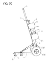
- the wheels 2 are pivotably supported at a lower portion of the frame unit 1 and a T-shaped handle 5 is arranged at an upper portion thereof. With this, by rotation of the wheels 2, the frame unit 1 can be moved (refer to FIGS. 1 to 3 ).
- the frame unit 1 is provided with the rotatable reel 3 for rolling up the above-mentioned hose H.
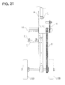
- the transmission circulating member 4 is looped around a rotary shaft 33 of the reel 3 and the rotational support shaft 21 of the wheels 2, and the reel 3 is rotated in association with rotation of the wheels 2.
- the sprockets are fixed respectively to the rotary shaft 33 of the reel 3 and the rotational support shaft 21 of the wheels 2, and a chain member is looped therearound to mesh with those sprockets.
- the reel 3 includes at least one of the single-layer-roll core 3A and the double-layer-roll core 3B replaceable with each other.
- Any one of the single-layer-roll core 3A and the double-layer-roll core 3B is removably fixed to a rotary-shaft portion 30a of a base plate 30 of the reel 3.
- the rotary-shaft portion 30a is provided at one point on the base plate 30.
- the rotary shaft 33 is provided to project from a rear surface of each of the cores, and the rotary shaft 33 of each of the cores can be passed through a hole portion of the rotary-shaft portion 30a of the base plate 30, and the sprocket can be mounted to a leading end side of the rotary shaft 33.
- the rotary-shaft portion 30a may be provided at two points on the reel so that the single-layer-roll core 3A and the double-layer-roll core 3B are respectively fastened.
- the single-layer-roll core 3A of the reel 3 is provided with a holding member 31A capable of pinching the coupler C of the above-mentioned hose H.
- the holding member 31A is formed of a pair of elastic plate bodies arranged to face each other (refer to FIGS. 4 and 5 ).
- the reel 3 is rotated in association with the rotation of the wheels 2 caused by traveling of the frame unit 1.
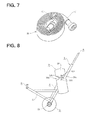
- the hose H is taken up around the coupler C as a central axis, which is pinched by the holding member 31A (refer to FIG. 7 ).
- a ratchet mechanism for transmitting rotation only in one direction of the wheels 2 to the reel 3 can be provided.
- the hose H is taken up by transmission of the rotation of the wheels 2 with respect to the reel 3, and when the frame unit 1 is moved backward (pulled), the hose H remains stopped by idling of the ratchet mechanism.
- a transporting operation is facilitated.
- an extended guide plate 30b is provided to extend from the base plate 30 of the reel 3.
- the hose H that has passed a hose guide 6 arranged on a front side of the frame unit 1 is led to the reel 3 by the extended guide plate 30b, and neatly taken up by the reel 3, with a side edge of the hose H being held in abutment with a surface of the extended guide plate 30b.
- the frame unit 1 is provided with a tapered leading inclined member 7 for bringing the hose H that has passed the hose guide 6 toward the extended guide plate 30b side.
- a protective cover may be appropriately mounted in case the coupler C is dragged when being taken up.
- a pair of recessed portions 30c and 30c are formed by the side of the rotary-shaft portion 30a of the base plate 30 of the reel 3 so that the taken-up hose H can be easily removed by fitting fingers into those recessed portions 30c and 30c (refer to FIG. 8 ).
- the double-layer rolling is performed mainly at the time of preparing a washed hose for next use.
- a projecting shaft 31B is provided to project from the double-layer-roll core 3B of the reel 3, and a hook bar 32B is arranged by the side of and in parallel with the projecting shaft 31B (refer to FIG. 9 ).
- a fold f formed by doubling over the hose H is hooked to the hookbar 32B (refer to FIG. 10 ) .
- the hose H is taken up around the projecting shaft 31B as a rotary shaft in a state of being looped around the projecting shaft 31B and the hook bar 32B.
- the hook bar 32B of the double-layer-roll core 3B mounted to the reel 3 is formed in a tapered shape that tapers toward the leading end so that the taken-up hose H can be easily pulled out.
- the hose looped around the projecting shaft 31B and the hook bar 32B is rolled therearound in a tensioned state.
- the distance between the shaft and the bar is smaller toward the leading end of the tapered part of the hook bar 32B.
- a slip mechanism for controlling to reduce the speed transmitted by the rotation of the wheels 2 and transmitting same to the reel 3.
- a clutch plate is arranged at a torque transmission part so that the reel 3 idles when the rotational speed of the wheel is high.
- the rotational speed of the reel 3 may be controlled to increase and decrease in association with an increase and decrease of the diameter of the taken-up part of the hose. In this way, the traveling speed of the take-up device and the take-up speed for the hose can be linked to each other. As a result, it is no longer necessary to replace two types of the sprockets, and the coupler C is prevented from being dragged during a take-up operation.
- this torque limiter mechanism detects tension load equal to or more than a predetermined value generated by the inherent weight or friction of a part of the hose H which has not yet been taken up, and separates at least a part of the drive unit. In this way, transmission of the rotational torque of the wheels 2 with respect to the reel 3 can be interrupted by spinning.
- a movable pops up projecting portion (inserted hard ball) which is provided in a clutch joint surface of a plate body and a recessed portion on another surface side are disengaged from each other. In this way, the transmission of the rotational torque can be interrupted.
- the handle 5 may be provided with an operation lever. By gripping the operation lever, the drive unit including the clutch plate coupled by a wire or the like is separated. In this way, the transmission of the rotational torque of the wheels 2 to the reel 3 can be interrupted.
- a large-diameter sprocket 41A corresponding to the single-layer-roll core 3A and a small-diameter sprocket 41B corresponding to the double-layer-roll core 3B can each be made removable to another end side of the rotary shaft 33 and those corresponding combinations can be made distinguishable from each other.
- cross-sections of the shaft portions for the fitting can be made different (for example, modified cross-section or polygonal cross-section) from each other.
- the rotational support shaft 21 of the wheels 2 is provided with a step portion 21a.
- the hose guide 6 can be raised about the wheels 2 as a fulcrum (refer to FIG. 5 ).
- a stand member 11b may be provided at a leading end of a beam portion 11 of the frame unit 1. By landing the stand member 11b, for example, when the take-up device is not used, the frame unit 1 can be stably placed (refer to FIG. 15 ).
- the wheels 2 and 2 are formed of a free wheel 2A rotatably and pivotably supported and an associative wheel 2B coupled to the transmission circulating member 4 so that rotational torque of the wheels can be transmitted, which are provided at respective end portions of the rotational support shaft 21.
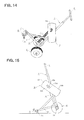
- the hose H After the hose H has been taken up by a predetermined length and the outer circumference of the taken-up part of the hose H has become larger than unit circumferences of the wheels 2A and 2B, as illustrated in FIG. 16 , the hose H starts to be tensioned in the front of the take-up device.
- the take-up device is moved forward as it is. Then, the take-up operation by the reel 3 is temporarily stopped, and hence the tensioned state of the hose H can be cancelled (refer to FIG. 18 ) .
- the take-up operation for the hose H can be restarted.
- the tensioned hose H can be returned into a loose state and taken up, and hence a user can comfortably continue the take-up operation without feeling load or frictional resistance of the hose H.
- a draining operation and the take-up operation for the hose H can be simultaneously performed, and the main body of the hose H or the coupler C is not dragged.
- a restoring operation can be smoothly performed.
- the beam portion 11 arranged on the front side of the frame unit 1 may be provided with a stretching mechanism 11a.
- the stretching mechanism 11a may be provided with a lock mechanism so that safety can be enhanced.
- the beam portion 11 of the frame unit 1 is not necessarily extendable, and may be disassembled and removed so that the frame unit 1 becomes compact.
- a rotary-shaft portion 30a may be provided at two points on the base plate 30 of the reel 3 .
- the single-layer-roll core 3A and the double-layer-roll core 3B can be fixed respectively to the rotary-shaft portions 30a.
- a link member 42 is looped around the rotary shafts 33 and 33 of the single-layer-roll core 3A and the double-layer-roll core 3B.
- both the rotary shafts can be coupled to each other so as to be rotated in a linked manner.
- the rotary-shaft portions 30a and 30a capable of respectively fixing the single-layer-roll core 3A and the double-layer-roll core 3B
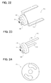
- the rotary-shaft portions 30a of the base plate 30 are provided with a plurality of hole portions (refer to FIG. 24 ).
- engaging projecting portions 34A and 34A (34B and 34B) and the rotary shafts 33 are provided to project from respective rear surfaces of the single-layer-roll core 3A and the double-layer-roll core 3B.
- the engaging projecting portions and the rotary shafts can be fitted into the rotary-shaft portions 30a.
- the rotary shaft 33 is inserted into the center of the rotary-shaft portion 30a, and the engaging projecting portions 34A and 34A (34B and 34B) are engaged by rotation into the elongated arc-shaped holes provided through the rotary-shaft portion 30a (refer to FIG. 24 ).
- the engaging projecting portions 34A and 34A 34B and 34B
Landscapes
- Health & Medical Sciences (AREA)
- Public Health (AREA)
- Business, Economics & Management (AREA)
- Emergency Management (AREA)
- Storing, Repeated Paying-Out, And Re-Storing Of Elongated Articles (AREA)
- Fire-Extinguishing By Fire Departments, And Fire-Extinguishing Equipment And Control Thereof (AREA)
Applications Claiming Priority (2)
| Application Number | Priority Date | Filing Date | Title |
|---|---|---|---|
| JP2009208447 | 2009-09-09 | ||
| PCT/JP2010/005505 WO2011030545A1 (ja) | 2009-09-09 | 2010-09-08 | 消防ホース巻き取り装置およびそれを用いた消防ホース巻き取り方法 |
Publications (2)
| Publication Number | Publication Date |
|---|---|
| EP2476465A1 true EP2476465A1 (de) | 2012-07-18 |
| EP2476465A4 EP2476465A4 (de) | 2017-08-02 |
Family
ID=43732224
Family Applications (1)
| Application Number | Title | Priority Date | Filing Date |
|---|---|---|---|
| EP10815145.7A Withdrawn EP2476465A4 (de) | 2009-09-09 | 2010-09-08 | Vorrichtung zur aufnahme eines feuerwehrschlauchs und verfahren zur aufnahme eines feuerwehrschlauchs mit dieser vorrichtung |
Country Status (6)
| Country | Link |
|---|---|
| US (1) | US8955786B2 (de) |
| EP (1) | EP2476465A4 (de) |
| JP (1) | JP5535223B2 (de) |
| KR (1) | KR20120054638A (de) |
| CA (1) | CA2773251C (de) |
| WO (1) | WO2011030545A1 (de) |
Families Citing this family (28)
| Publication number | Priority date | Publication date | Assignee | Title |
|---|---|---|---|---|
| US9004391B2 (en) * | 2011-02-01 | 2015-04-14 | Roll N Rack Llc | Apparatus for hand winding a hose line |
| CN102801061A (zh) * | 2011-05-24 | 2012-11-28 | 海洋王照明科技股份有限公司 | 一种绕线盘装置 |
| US9908737B2 (en) * | 2011-10-07 | 2018-03-06 | Perfectvision Manufacturing, Inc. | Cable reel and reel carrying caddy |
| CN103601041B (zh) * | 2013-11-28 | 2016-08-24 | 黄焕胜 | 便携式自动水带收卷器 |
| US10414624B1 (en) * | 2014-09-23 | 2019-09-17 | Kevin D. Berry | Motorized flat web winder |
| DE102014115361A1 (de) * | 2014-10-22 | 2016-04-28 | Wilhelm Barth GmbH & Co. KG Feuerwehrtechnik | Vorrichtung zum Aufwickeln von Schläuchen, vorzugsweise Feuerwehr-Schläuchen |
| US9643630B1 (en) | 2016-03-01 | 2017-05-09 | Thomas R. Smith | Large diameter hose draining device |
| USD797891S1 (en) * | 2016-04-27 | 2017-09-19 | Wen Chang Wang | Water spray base for firefighting |
| GB2550895A (en) * | 2016-05-27 | 2017-12-06 | Hosehelp Ltd | A method and apparatus for rolling an elongate flexible member such as a hose |
| WO2017208383A1 (ja) * | 2016-06-01 | 2017-12-07 | 栄冠商事株式会社 | 長尺モノ巻き取り撤収機および該長尺モノ巻き取り撤収機を用いた長尺モノの巻き取り方法 |
| US9884214B1 (en) | 2016-10-11 | 2018-02-06 | Naieef F. N. M. D. Al-Mutairi | Hose winding device |
| US10512807B2 (en) * | 2016-11-15 | 2019-12-24 | James Madding | Portable fire hose dewatering device |
| CN106902486B (zh) * | 2017-01-23 | 2019-09-24 | 重庆市计量质量检测研究院 | 一种用于火灾救助的移动机械装置 |
| CN107715355A (zh) * | 2017-11-01 | 2018-02-23 | 陈小辉 | 一种消防用卷水管设备 |
| KR200490198Y1 (ko) * | 2019-04-19 | 2019-10-08 | 김성림 | 농업용수 공급용 호스 언와인더 |
| CN110681093B (zh) * | 2019-10-29 | 2021-06-04 | 南京溧水高新产业股权投资有限公司 | 一种可收纳水带的消防水炮 |
| CN110861979A (zh) * | 2019-10-30 | 2020-03-06 | 樊轩 | 适用于果树灌溉的水管卷带装置 |
| KR20220001250U (ko) | 2020-11-25 | 2022-06-02 | 정은경 | 소방호스 권취기 |
| JP7470415B2 (ja) * | 2020-12-24 | 2024-04-18 | 株式会社ナベル | ホース巻取装置 |
| CN113058178B (zh) * | 2021-04-01 | 2022-08-26 | 嘉兴倍创网络科技有限公司 | 可快速安装使用的移动式地铁轨道交通消防设备 |
| US11633638B2 (en) | 2021-04-20 | 2023-04-25 | Daniel James Corrigan | Fire hose reeling system |
| CN113233258B (zh) * | 2021-05-14 | 2022-06-10 | 山西怡嘉智能消防工程有限公司 | 一种专用于消防水带的快速卷收装置 |
| CN113371537B (zh) * | 2021-06-02 | 2023-07-11 | 山东玻纤集团股份有限公司 | 一种复合玻璃纤维卷绕机及其使用方法 |
| TWI775594B (zh) * | 2021-09-08 | 2022-08-21 | 陳治華 | 具清洗功能的消防水帶捲收裝置 |
| US20250256939A1 (en) * | 2022-05-10 | 2025-08-14 | Safe Roll Pty. Ltd. | A device for winding up a hose |
| KR102518083B1 (ko) * | 2022-08-01 | 2023-04-05 | 황하준 | 수동식 소방호스 내측 감압식 권취기 |
| CN116101847B (zh) * | 2022-12-06 | 2025-09-23 | 浙江恒强科技股份有限公司 | 一种用于纺织纱线的恒定张力控制设备及控制方法 |
| US20250214803A1 (en) * | 2024-01-03 | 2025-07-03 | Victoria Elizabeth Agate | Figure 8 Hose Roller |
Family Cites Families (41)
| Publication number | Priority date | Publication date | Assignee | Title |
|---|---|---|---|---|
| US190231A (en) * | 1877-05-01 | Improvement in hose-carriages | ||
| US231399A (en) * | 1880-08-24 | John s | ||
| US763340A (en) * | 1903-12-28 | 1904-06-21 | James S Brandon | Vehicle attachment for taking up and distributing wire. |
| US1458861A (en) * | 1922-10-21 | 1923-06-12 | William A Springowski | Self-winding hose reel |
| US1545546A (en) * | 1924-09-23 | 1925-07-14 | Walter B Brittin | Hose reel |
| US2016625A (en) * | 1934-01-02 | 1935-10-08 | Carrier Milton Leroy | Hose carriage |
| US2498609A (en) * | 1948-01-12 | 1950-02-21 | Reil Ben | Automatic electric wire roller for electric power lawn mowers |
| US3504866A (en) * | 1968-05-06 | 1970-04-07 | Corod Mfg Ltd | Transport reel |
| US3473755A (en) * | 1968-07-15 | 1969-10-21 | Brown & Brown Inc | Automatic laying and retrieving ground cover apparatus |
| US3529786A (en) * | 1968-10-14 | 1970-09-22 | Lenhard Holden | Cord storage reel |
| US4198010A (en) * | 1978-10-20 | 1980-04-15 | Knapp Orville J | Hose winding apparatus |
| USRE32510E (en) * | 1982-11-29 | 1987-09-29 | Suncast Corporation | Hose storage apparatus |
| US4723568A (en) * | 1985-11-29 | 1988-02-09 | Adams Truman W | Hose reel mechanism |
| US4886409A (en) * | 1988-02-10 | 1989-12-12 | Inland Steel & Forgings Ltd. | Big bale unroller |
| JP2520754Y2 (ja) * | 1988-05-21 | 1996-12-18 | 良喜 浅野 | ホースリール |
| US5213278A (en) * | 1988-06-23 | 1993-05-25 | A/S Jens Villadsens Fabriker | Apparatus for applying web shaped material to a substrate |
| US4892265A (en) * | 1988-08-26 | 1990-01-09 | Cox Lloyd D | Wrap winder with reversible mounting bracket |
| JPH0298960A (ja) | 1988-10-05 | 1990-04-11 | Nec Corp | 半導体装置の製造方法 |
| JPH0298960U (de) * | 1989-01-27 | 1990-08-07 | ||
| US5092543A (en) | 1989-09-27 | 1992-03-03 | General Electric Company | Spacecraft attitude control with avoidance constraint |
| US5273257A (en) * | 1990-05-31 | 1993-12-28 | Perkins John J | Apparatus for controlling movement of a tether in a conduit |
| JP2811522B2 (ja) * | 1992-12-04 | 1998-10-15 | 小倉クラッチ株式会社 | 消防用ホースの巻取り装置 |
| US5388609A (en) * | 1994-01-06 | 1995-02-14 | Ghio; Gary L. | Hose reel cart |
| US5957400A (en) * | 1998-05-22 | 1999-09-28 | Brannen; David B. | Self winding hose reel |
| US5988552A (en) * | 1998-11-12 | 1999-11-23 | Suncast Corporation | Portable hose reel cart having a folding handle |
| DE10036315A1 (de) * | 2000-07-26 | 2002-02-07 | Gardena Kress & Kastner Gmbh | Fahrbare Transporteinrichtung für Wickelgut |
| US6591744B2 (en) * | 2001-06-08 | 2003-07-15 | David Peek | Wheeled squeegee for fire hose |
| JP2003070931A (ja) * | 2001-09-04 | 2003-03-11 | Kanagawa Pump Kk | 消防ホース巻取機 |
| US6811110B2 (en) * | 2002-11-12 | 2004-11-02 | Cheony-Sun Tsao | Reeling device for fire hoses |
| CA2412269A1 (en) * | 2002-11-21 | 2004-05-21 | Gilbert Laporta | Cord take-up reel for electric powered lawn mower |
| US7448110B2 (en) * | 2003-07-15 | 2008-11-11 | Best G Robert | Fire hose retrieval winch |
| BE1016086A3 (nl) * | 2004-05-10 | 2006-02-07 | Dethier Livin Fernand Georges | Inrichting voor het op- en afwikkelen van slangen, kabels of dergelijke. |
| US8360353B2 (en) * | 2004-09-10 | 2013-01-29 | Mosher James L | Portable winding and reeling apparatus |
| WO2006046946A2 (en) * | 2004-10-22 | 2006-05-04 | Javier Fernandez | Apparatus for draining and transporting large diameter hoses |
| US7152672B1 (en) * | 2005-10-27 | 2006-12-26 | Gipson Tommie C | Combination workover and drilling rig |
| JP3125700U (ja) * | 2006-07-19 | 2006-09-28 | 徳永電機株式会社 | 消防ホース巻取機 |
| JP2008105808A (ja) * | 2006-10-25 | 2008-05-08 | Mitsubishi Heavy Ind Ltd | 印刷機および給紙装置による紙継ぎ方法 |
| US7398979B2 (en) * | 2006-11-01 | 2008-07-15 | Hsiu-Man Yu Chen | Reel stand |
| JP2009196815A (ja) * | 2008-02-20 | 2009-09-03 | Keiji Takuwa | 消防用ホース巻取機 |
| US7954747B2 (en) * | 2008-06-13 | 2011-06-07 | Chudy Group, LLC | Pouch package spooler and method of pouch package web management |
| US8464974B2 (en) * | 2008-09-10 | 2013-06-18 | Sonny Schillo | Device for applying sheet material and method thereof |
-
2010
- 2010-09-08 US US13/393,400 patent/US8955786B2/en not_active Expired - Fee Related
- 2010-09-08 JP JP2011530751A patent/JP5535223B2/ja not_active Expired - Fee Related
- 2010-09-08 WO PCT/JP2010/005505 patent/WO2011030545A1/ja not_active Ceased
- 2010-09-08 KR KR20127007068A patent/KR20120054638A/ko not_active Abandoned
- 2010-09-08 CA CA2773251A patent/CA2773251C/en not_active Expired - Fee Related
- 2010-09-08 EP EP10815145.7A patent/EP2476465A4/de not_active Withdrawn
Non-Patent Citations (1)
| Title |
|---|
| See references of WO2011030545A1 * |
Also Published As
| Publication number | Publication date |
|---|---|
| CA2773251A1 (en) | 2011-03-17 |
| EP2476465A4 (de) | 2017-08-02 |
| KR20120054638A (ko) | 2012-05-30 |
| JP5535223B2 (ja) | 2014-07-02 |
| CA2773251C (en) | 2016-08-09 |
| WO2011030545A1 (ja) | 2011-03-17 |
| JPWO2011030545A1 (ja) | 2013-02-04 |
| US8955786B2 (en) | 2015-02-17 |
| US20120153067A1 (en) | 2012-06-21 |
Similar Documents
| Publication | Publication Date | Title |
|---|---|---|
| US8955786B2 (en) | Device for taking up fire-fighting hose and method for taking up fire-fighting hose | |
| JP5952496B2 (ja) | ハンドラッピング装置 | |
| JP2012526018A (ja) | 切り出し装置 | |
| US10272935B1 (en) | Hand cart for lifting and supporting an item for holding windable material and associated method | |
| US4747254A (en) | Web threading device | |
| CN107572317A (zh) | 机械式电缆盘移动收放车 | |
| JP2016160018A (ja) | 長尺モノ巻き取り撤収機および該長尺モノ巻き取り撤収機を用いた長尺モノの巻き取り方法 | |
| US2563377A (en) | Wire handling apparatus | |
| CN104760760B (zh) | 托盘货物包装装置 | |
| JP2003320985A (ja) | 自転車 | |
| JP6305817B2 (ja) | 巻取装置 | |
| JP7637385B2 (ja) | ケーブル巻取り補助装置 | |
| CN210418813U (zh) | 设有用于施放电缆线的辅助装置的工程车 | |
| WO2017208383A1 (ja) | 長尺モノ巻き取り撤収機および該長尺モノ巻き取り撤収機を用いた長尺モノの巻き取り方法 | |
| JP7080758B2 (ja) | ホースの巻取装置 | |
| US1334361A (en) | Reeling and unreeling device | |
| JP2024147356A (ja) | ホース自動巻取り装置 | |
| CN113562551B (zh) | 用于电力工程施工的线缆收放装置 | |
| WO1991000235A1 (en) | Hose winding device | |
| US8578847B2 (en) | Apparatuses and methods for fluid evacuation | |
| JP2013133095A (ja) | 後進装置 | |
| JP6417172B2 (ja) | 固定構造及びその固定構造を用いた搬送機器 | |
| CH289565A (fr) | Dispositif de manutention de bobines. | |
| JP2001186818A (ja) | マルチフィルム巻取り装置 | |
| JP3433189B2 (ja) | 被覆シートの巻取り装置 |
Legal Events
| Date | Code | Title | Description |
|---|---|---|---|
| PUAI | Public reference made under article 153(3) epc to a published international application that has entered the european phase |
Free format text: ORIGINAL CODE: 0009012 |
|
| 17P | Request for examination filed |
Effective date: 20120326 |
|
| AK | Designated contracting states |
Kind code of ref document: A1 Designated state(s): AL AT BE BG CH CY CZ DE DK EE ES FI FR GB GR HR HU IE IS IT LI LT LU LV MC MK MT NL NO PL PT RO SE SI SK SM TR |
|
| DAX | Request for extension of the european patent (deleted) | ||
| RIC1 | Information provided on ipc code assigned before grant |
Ipc: B65H 54/58 20060101ALI20170314BHEP Ipc: A62C 33/04 20060101AFI20170314BHEP |
|
| RA4 | Supplementary search report drawn up and despatched (corrected) |
Effective date: 20170629 |
|
| RIC1 | Information provided on ipc code assigned before grant |
Ipc: B65H 54/58 20060101ALI20170623BHEP Ipc: A62C 33/04 20060101AFI20170623BHEP |
|
| STAA | Information on the status of an ep patent application or granted ep patent |
Free format text: STATUS: THE APPLICATION IS DEEMED TO BE WITHDRAWN |
|
| 18D | Application deemed to be withdrawn |
Effective date: 20180130 |