EP2476516B1 - Vorrichtung zur Winkelausrichtung der Welle eines Energieaggregats - Google Patents
Vorrichtung zur Winkelausrichtung der Welle eines Energieaggregats Download PDFInfo
- Publication number
- EP2476516B1 EP2476516B1 EP12151101.8A EP12151101A EP2476516B1 EP 2476516 B1 EP2476516 B1 EP 2476516B1 EP 12151101 A EP12151101 A EP 12151101A EP 2476516 B1 EP2476516 B1 EP 2476516B1
- Authority
- EP
- European Patent Office
- Prior art keywords
- pawl
- gripping member
- rotation
- engaging member
- jaws
- Prior art date
- Legal status (The legal status is an assumption and is not a legal conclusion. Google has not performed a legal analysis and makes no representation as to the accuracy of the status listed.)
- Active
Links
Images


Classifications
-
- B—PERFORMING OPERATIONS; TRANSPORTING
- B25—HAND TOOLS; PORTABLE POWER-DRIVEN TOOLS; MANIPULATORS
- B25B—TOOLS OR BENCH DEVICES NOT OTHERWISE PROVIDED FOR, FOR FASTENING, CONNECTING, DISENGAGING, OR HOLDING
- B25B13/00—Spanners; Wrenches
- B25B13/48—Spanners; Wrenches for special purposes
-
- B—PERFORMING OPERATIONS; TRANSPORTING
- B25—HAND TOOLS; PORTABLE POWER-DRIVEN TOOLS; MANIPULATORS
- B25B—TOOLS OR BENCH DEVICES NOT OTHERWISE PROVIDED FOR, FOR FASTENING, CONNECTING, DISENGAGING, OR HOLDING
- B25B13/00—Spanners; Wrenches
- B25B13/46—Spanners; Wrenches of the ratchet type, for providing a free return stroke of the handle
- B25B13/461—Spanners; Wrenches of the ratchet type, for providing a free return stroke of the handle with concentric driving and driven member
- B25B13/462—Spanners; Wrenches of the ratchet type, for providing a free return stroke of the handle with concentric driving and driven member the ratchet parts engaging in a direction radial to the tool operating axis
- B25B13/463—Spanners; Wrenches of the ratchet type, for providing a free return stroke of the handle with concentric driving and driven member the ratchet parts engaging in a direction radial to the tool operating axis a pawl engaging an externally toothed wheel
-
- F—MECHANICAL ENGINEERING; LIGHTING; HEATING; WEAPONS; BLASTING
- F02—COMBUSTION ENGINES; HOT-GAS OR COMBUSTION-PRODUCT ENGINE PLANTS
- F02B—INTERNAL-COMBUSTION PISTON ENGINES; COMBUSTION ENGINES IN GENERAL
- F02B77/00—Component parts, details or accessories, not otherwise provided for
- F02B77/08—Safety, indicating, or supervising devices
- F02B77/081—Safety, indicating, or supervising devices relating to endless members
-
- F—MECHANICAL ENGINEERING; LIGHTING; HEATING; WEAPONS; BLASTING
- F01—MACHINES OR ENGINES IN GENERAL; ENGINE PLANTS IN GENERAL; STEAM ENGINES
- F01L—CYCLICALLY OPERATING VALVES FOR MACHINES OR ENGINES
- F01L2303/00—Manufacturing of components used in valve arrangements
- F01L2303/01—Tools for producing, mounting or adjusting, e.g. some part of the distribution
-
- F—MECHANICAL ENGINEERING; LIGHTING; HEATING; WEAPONS; BLASTING
- F01—MACHINES OR ENGINES IN GENERAL; ENGINE PLANTS IN GENERAL; STEAM ENGINES
- F01L—CYCLICALLY OPERATING VALVES FOR MACHINES OR ENGINES
- F01L2303/00—Manufacturing of components used in valve arrangements
- F01L2303/02—Initial camshaft settings
Definitions
- the invention relates to power groups, and more particularly to power units of railway vehicles.
- a power unit for a railway vehicle for example a motor
- a heat engine the latter comprises a motor shaft comprising a crank shaft line and a distribution shaft line with cams actuating rocker arms (or any other valve driving device) and valves and that these two lines of motor shaft are linked in their rotational movements.
- the functional clearance between the rockers and the valves is altered over time during the use of the engine. A setting of this game is therefore necessary, for example every 1500 hours.
- the turning step is performed by an operator who accesses the motor of the power group by a hatch disposed under the power unit and allowing access to the power unit. engine.
- the rail vehicle is then placed above a pit, to allow the operator to access the power group engine through said trap.
- the operator can then use a wrench or crank adapted to rotate the motor shaft to the chosen position.
- a gripping member such as an annular ring, is mounted on the portion of the motor shaft which extends out of the motor housing to allow the turning of the shaft engine.
- the gripping member comprises a plurality of peripheral orifices distributed angularly and adapted to receive the end of a tool called a bar to be turned.
- the object of the invention is to remedy these drawbacks and relates to a device for a vehicle power unit, in particular a railway power unit, comprising at least one motor whose driving shaft is provided with a gripping member which is integral with it in rotation .
- the device according to the invention is remarkable in that it comprises a gripping member adapted to be mounted on the gripping member and associated with at least one pawl arranged for, in a direction of rotation, to secure in rotation the gripping member and the gripping member and for, in the opposite direction of rotation, detaching in rotation said gripping member from said gripping member.
- Such a ratchet mechanism reduces the number of maneuvers during the turning step of the motor shaft because the operator is satisfied with a movement back and forth and no longer has to enter and exit the bar to turn in the orifices, thus facilitating the turning step.
- the gripping member comprises, on its outer contour, a notched portion adapted, on the one hand, not to engage with the pawl to allow rotation of the gripping member relative to, or relatively, to the gripping member in a specific direction of the gripping member and, secondly, to engage with the pawl to prevent the rotation of the gripping member relative to, or relatively to, the organ in the opposite direction of rotation.
- the rotation of the gripping member thus causes, by fastening via the pawl, the rotation of the gripping member and therefore of the motor shaft in said opposite direction of rotation.
- the drive shaft further comprises a second gripping member which is integral in rotation and the gripping member is adapted to be mounted on the first gripping member and the second gripping member. , and is associated with at least one second pawl arranged for, in a direction of rotation, opposite to the direction of rotational rotation rotation of the gripping member and the first gripping member, securing in rotation the gripping member and the second gripping member and for, in the opposite direction of rotation, detaching in rotation said gripping member of said second gripping member.
- the device further comprises means for switching the direction of rotation arranged to activate the use of the first pawl or second pawl.
- the first pawl and the second pawl are mounted integral on the same axis, parallel to the longitudinal axis of the drive shaft and the device is configured so that the switching means of the direction of rotation are arranged to tilt, around said axis, the first pawl in a first engagement position, with the first engagement member, and the second pawl in a second engagement position, with the second engagement member. This facilitates the switching of the means for using either the first pawl or the second pawl.
- the use of two first pawls and two second pawls makes it possible to apply an equivalent and therefore balanced force, on either side of the first gripping member or the second gripping member, following the selected direction of rotation of the gripping member, thereby making the rotation of the device easier.
- the device may comprise two first pawls and two second pawls, a first pawl and a second pawl being mounted integral on a first axis, a first pawl and a second pawl being mounted integral on a second axis, the first and second axes and being arranged symmetrically on either side of the longitudinal axis of the motor shaft.
- the second gripping member comprises, on its outer contour, a notched portion.
- This notched portion is able, on the one hand, not to engage with the second pawl to allow rotation of the gripping member relative to, or relatively to, the second gripping member in a determined direction of the organ on the other hand, to engage with the second pawl to prevent the rotation of the gripping member relative to, or relatively to, the second gripping member in the opposite direction of rotation.
- the rotation of the gripping member thus causes, by securing via the second pawl, the rotation of the second gripping member and therefore the motor shaft in said opposite direction of rotation.
- the notches of the notched portion of the first gripping member and those of the notched portion of the second gripping member are preferably reversed.
- the notches of the notched portion of the first member have a shape adapted to allow the rotation of the gripping member relative to the first gripping member and those of the notched portion of the second gripping member have a shape adapted to prevent the rotation of the gripping member relative to the second gripping member in a determined direction of rotation of the gripping member.
- the notches of the notched portion of the first gripping member have a shape adapted to prevent the rotation of the gripping member relative to the first gripping member and those of the notched portion of the second gripping member have a suitable shape. to allow the rotation of the gripping member relative to the second gripping member in the opposite direction to said determined direction of rotation of the gripping member.
- the gripping member comprises two jaws hinged about an axis, parallel to the longitudinal axis of the drive shaft, arranged to be open, in a disengagement position, for example to transport, and to be mounted on the first gripping member in a position of use of the device.
- a jaw system makes the device removable. The device can thus easily be mounted or removed from the first engaging member of the motor shaft.
- the jaws are furthermore arranged to be mounted on the first gripping member and the second gripping member in a position of use.
- the device can thus easily be mounted or removed from the first and second gripping members of the motor shaft.
- the device further comprises means for locking the jaws.
- These locking means make it possible to maintain the device on the first and second organs of taken mounted in rotation with the motor shaft.
- Blocking means may also make it possible to maintain means for actuating the device.
- the locking means comprise, according to one aspect of the invention, a first locking handle arranged to be screwed onto the threaded portion of a first axis and a second locking handle arranged to be screwed onto the threaded portion of a second axis.
- Such locking handles have the advantage of being easily manipulated by an operator.
- they may be more or less tightened or loosened to lock or unlock the jaws of the gripping member. For example, one of them can be removed and the other loosened to allow articulation of the jaws and thus mounting, removal or transport of the device.
- the device comprises at least one closure latch of the jaws whose two ends are arranged to be each fixed on one of jaws with two wheels. This closing latch keeps the jaws integral during assembly, removal or use of the device on the first and second gripping members mounted integral rotation of the motor shaft.
- the means for switching the direction of rotation may comprise at least one knurled wheel arranged to engage the first pawl with the first engagement member or the second pawl with the second engagement member.
- a knurled wheel is an easy switching means to handle for an operator.
- the device further comprises actuating means adapted to allow an operator to operate the gripping member.
- actuating means make it possible to transmit the force exerted by the operator to the device to rotate it.
- the device comprises, according to another characteristic of the invention, moreover an orifice, such as for example a thrust notch, arranged to receive the actuating means.
- an orifice such as for example a thrust notch
- the actuating means comprise a bar to be turned.
- a bar to turn can operate the device in reduced angular spaces.
- Such a turn bar also allows an operator to easily rotate the device using leverage.
- the device may further comprise an orifice arranged to receive means of transport of the device.
- the means of transport advantageously comprise a carrying handle. This makes it possible to manipulate the device in order to transport it or to put it in place on the first and second gripping members of the motor shaft.
- the invention also relates to a power unit of a vehicle, in particular a railway vehicle.
- the power unit comprises at least one motor having a motor shaft.
- the motor shaft comprises a gripping member mounted to rotate with the motor shaft.
- the power unit further comprises a device as described above.
- an operator 2 actuates a bar to turn 1a to rotate the device 20 as shown in FIG. figure 1 .
- the operator 2 can perform, by means of the bar to turn 1 a, a movement of back and forth on the latter to rotate the device 20 and thus allow the angular orientation of the drive shaft 10 and therefore the adjustment of the different rockers connected to the motor shaft 10.
- a position of use of the device 20 according to the invention corresponds to the mounting of the device 20 on at least one gripping member of a motor shaft 10.
- a gripping member allows taking or training by at least one other element such as a pawl as described below.
- the device 20 according to the invention is mounted or flanged, in a use position, on a first gripping member 11 and a second gripping member 13.
- the first gripping member 11 is mounted to rotate with the shaft motor 10 of a power group motor. In other words, the first gripping member 11 is static relative to the drive shaft 10.
- the second gripping member 13 is mounted to rotate with the drive shaft 10 of a motor of the power unit .
- first gripping member 11 and the second gripping member 13 are a single circular piece with double notches (or teeth) 15 and 17 reversed.
- first gripping member 11 and the second gripping member 13 may each be formed of a separate piece mounted to rotate with the shaft 10.
- the first gripping member 11 and the second gripping member 13 may be mounted permanently on the motor shaft 10, for example by welding, or be removable to be mounted punctually on the motor shaft 10.
- the first gripping member 11 is a ring having a notched portion 15 and the second gripping member 13 is a ring having a notched portion 17.
- the notches of the notched portions 15 and 17 respectively of the first gripping member 11 and the second member tap 13 are reversed.
- the notches may be for example wave-shaped or any form allowing the drive of the member by a pawl in a determined direction of rotation and preventing the drive of the member by said pawl in the opposite direction of rotation.
- This ratchet rotation drive mechanism, and the parts and shapes of parts necessary for the proper functioning of such a mechanism, are known to those skilled in the art.
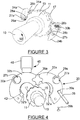
- the device 20 comprises a gripping member 22 adapted to be mounted on the gripping member 11 and the gripping member 13.
- the gripping member 22 comprises two jaws formed of four half-rings 32a, 32'a, 32b, 32'b.
- the two jaws may be formed respectively of two half crowns instead of four.
- the half crowns can be for example made of aluminum or aluminum alloy resistant to efforts.
- the device according to the invention comprises at least one pawl.
- the device 20 comprises four pawls 24a, 24b, 26a and 26b. More precisely, in the illustrated embodiment of the invention, the device 20 comprises two opposing systems with two independent detachable ratchets comprising two first pawls 24a and 24b and two second pawls 26a and 26b.
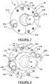
- the jaws 32a, 32'a, 32b and 32'b comprise, as described in figure 2 , housing respectively 23a, 25a, 23b and 25b.
- the housings 23a and 25a, symmetrical in the jaws 32a, 32'a are arranged to receive a first pawl 24a and a second pawl 26a.
- the housings 23b and 25b, symmetrical in the jaws 32b, 32'b of the housings 23a and 25a are arranged to receive a first pawl 24b and a second pawl 26b.
- the device 20 also comprises means for switching the direction of rotation arranged to activate the use of (or disengage) two (first) pawls 24a and 24b or two (second) pawls 26a or 26b.
- the switching means are arranged to tilt the first pawls 24a and 24b between an engagement position with a first engagement member 11 and a disengagement position vis-à-vis the first engagement member 11 , that is to say, not engaged with the first gripping member 11.
- the switching means are arranged to tilt the second pawls, respectively 26a or 26b, between an engagement position with a second member of 13 and a release position vis-à-vis the second gripping member 13.
- the switching means are used to select the first pawls 24a and 24b or the second pawls 26a and 26b, that is to say to select the first gripping member 11 or the second gripping member 13 with which the ratchets chosen go 'engage according to the meaning of envisaged rotation of the motor shaft by the operator.
- the pawls 24a and 26a are engaged at the same time, ie respectively engaged with both the first gripping member 11 and the second gripping member 13, the device 20 is locked in rotation relative to the motor shaft.
- the switching means comprise two sets formed of two rotary knurled wheels respectively 29a, 29b and 30a, 30b and two tilt axes, respectively 28a and 28b.
- the two rotary knurled wheels 29a, 29b are mounted integral on an axis 27a.
- a wheel 31a is used to lock or unlock the rotary knurling wheels 29a, 29b.
- the two rotary knurled wheels 30a, 30b are mounted integral on an axis 27b.
- a wheel 31b is used to lock or unlock the rotary knurling wheels 30a, 30b.
- the first pawl 24a and the second pawl 26a are mounted integral on the axis 27a.
- the first pawl 24b and the second pawl 26b are mounted integral on the axis 27b.
- the axes 27a and 27b are each symmetrically disposed on a jaw (32a, 32'a) and (32b, 32'b).
- the two rotary knurled wheels 29a, 29b rotate around an axis 27a to oscillate a tilt axis 28a which raises one or other of the pawls 24a and 26a.
- the two rotary knurling wheels 30a, 30b rotate around an axis 27b to oscillate a tilting axis 28b which raises one or other of the pawls 24b and 26b.
- the rotary knurling wheels 29a, 29b and 30a, 30b are arranged to move in rotation between a first position and a second position.
- the first position corresponds to the engagement of a first pawl (24a, 24b), with the first engagement member 11.
- the second position corresponds to the engagement of a second pawl (26a, 26b) with a second pawl socket 13 described in references to Figures 3 to 5 and 8 .
- the knurled wheel 29a is positioned in a second position corresponding to the engagement of a pair of second pawls 26a and 26b with the notched portion 17 of the second gripping member 13.
- the pawls of the pair of first pawls (24a, 24b) are not engaged with the notched portion 15 of the first engagement member 11 so that only the second engagement member 13, and therefore the drive shaft 10, is rotated by the gripping member 22 in a given direction.
- the pawls of the pair of second pawls (26a, 26b) are arranged to, on the one hand, allow the rotation of the gripping member 22 by relative to the first gripping member 11 in a given direction and, secondly, prevent the rotation of the gripping member 22 relative to the second gripping member 13 in the opposite direction.
- the notches of the notched portion 17 are arranged to allow the second pawls 26a, 26b to allow or not the rotation of the second gripping member 13 in the direction of rotation of the gripping member 22.
- the second pawls 26a, 26b will thus not cause the second gripping member 13 and thus allow rotation of the gripping member 22 relative to the second member taking hold 13 while in the opposite direction of rotation, referenced rotation direction 50 on the figures 2 and 3 and 5 to 8 , the second pawls 26a, 26b will drive the second engagement member 13 and thus the drive shaft 10 in the direction of rotation 50.
- the switching means 29a, 29b and 30a, 30b are in a second position so that the first pawls 24a, 24b are not engaged with the notches of the first engagement member 11 while the second pawls 24a, 24b are engaged with the notches of the second grip member 13.
- Each pawl can be arranged to operate with a return spring.
- a return spring being able to press the pawl, in an engagement position, with the first engagement member 11 or the second engagement member 13, more precisely to press the pawl, in an engagement position, against a notch of the first grip member 11 or the second grip member 13.
- the locking means of the jaws 32a, 32'a, 32b and 32'b of the gripping member 22 may comprise clips for clipping the jaws 32a, 32 32b, 32'b between them.
- the locking handle 36b also maintains actuating means 1.
- actuating means 1 comprise a turn bar 1a allowing an operator 2 to use the device 20 to turn the drive shaft 10 as described below. above.
- An orifice may be provided in the jaws 32a, 32'a, 32b, 32'b to accommodate at least a portion of the actuating means 1, such as for example an end of the bar to turn 1a.
- a transport handle 46 can transport the device 10.
- the transport handle 46 may for example be magnetized to lift and transport the device 10.
- the device 10 may also include holding means and / or an orifice 44 for inserting the device. transport handle 46 and thus transport or manipulate the device 10. In this disengagement position, at least one wheel 39b has been removed to allow the closure latch 38 to be detached from the half-crown 32b, the locking handle 36b has been removed. removed and the locking handle 36a has been loosened in order to be able to remove the device 10 from the first gripping member 11 and the second gripping member 13 mounted integral with the driving shaft 10.
- the device 20 is presented inverted above the drive shaft 10, opened and blocked by the locking handle 36a to allow mounting of the device 20 on the drive shaft 10.
- the switching means 29a, 29b and 30a, 30b can be pre-locked in a pawl position corresponding to a determined direction of rotation, each of the two positions of the switching means 29a, 29b and 30a, 30b corresponding to a direction of rotation. determined or opposite direction of rotation.
- the locking handle 36a can be unscrewed so that the jaws 32a, 32'a, 32b, 32'b close by gravity.
- the closing latch 38 is fixed on the jaws 32a, 32'a, 32b, 32'b with the two wheels 39a and 39b to maintain them integral.
- the closing latch 38 holds the half-rings 32a and 32b integral.
- the locking handle 36a is mounted as illustrated on the figure 6 and can be tightened in the locking position to freeze the jaws 32a, 32'a, 32b, 32'b.
- the device 20 can, after mounting the closing latch 38 be rotated 180 ° in the predetermined free direction of rotation by the switching means 29a, 29b and 30a, 30b to mount the actuating means 1.
- closure pin 37b, washers and the locking handle 36b can then be mounted and the locking handle 36b screwed to hold the actuating means 1 on the jaws 32a, 32'a, 32b, 32'b.
- the actuating means 1 are mounted on the device 20.
- At least one orifice 42 such as for example a thrust groove, can be provided to allow the actuating means 1 to drive the device 20 in rotation by the action of the operator 2 on the bar to be turned 1 a.
- the threaded knobs 31a and 31b make it possible to block the rotary knurling wheels 29a, 29b and 30a, 30b, respectively, of the switching means, in particular in the position of use of the device 20.
- the axes 37a and 37b of the locking means provide respectively with the handles 36a and 36b the locking functions of the jaws 32a, 32'a, 32b, 32'b.
- the rotary knurling wheels 29b and 30b (and, in extenso, 29a and 30a), in their position as described on the Figures 2 to 8 , allow to turn the motor shaft clockwise from the front.
- unscrewing the threaded wheels 31a and 31b By unscrewing the threaded wheels 31a and 31b, turning the rotary knurling wheels 29b and 30b (and, extensively, 29a and 30a) in the opposite direction and re-screwing the threaded wheels 31a and 31b, this will have the effect of turn the motor shaft counterclockwise.
Landscapes
- Engineering & Computer Science (AREA)
- Mechanical Engineering (AREA)
- Chemical & Material Sciences (AREA)
- Combustion & Propulsion (AREA)
- General Engineering & Computer Science (AREA)
- Manipulator (AREA)
Claims (14)
- Vorrichtung (20) für ein Energieaggregat eines Fahrzeugs, insbesondere eines Schienenfahrzeugs, wobei die Vorrichtung mindestens einen Motor umfasst, dessen Motorwelle (10) mit einem Aufnahmeorgan (11) ausgestattet ist, das damit in Rotation fest verbunden ist, und das auf seinem äußeren Umfang einen gezahnten Abschnitt (15) umfasst, wobei die Vorrichtung (20) dadurch gekennzeichnet ist, dass sie ein Greiforgan (22) umfasst, das ausgelegt ist, um auf dem Aufnahmeorgan (11) montiert und mindestens mit einer ersten Sperrklinke (24a, 24b) assoziiert zu sein, die angeordnet ist, um in einer Rotationsrichtung in Rotation das Greiforgan (22) und das Aufnahmeorgan (11) fest miteinander zu verbinden, wobei die erste Sperrklinke (24a, 24b) ausgelegt ist, um mit dem gezahnten Abschnitt (15) einzugreifen, um die Rotation des Greiforgans (22) mit Bezug auf das Aufnahmeorgan (11) zu verhindern, und um, in der entgegengesetzten Rotationsrichtung, in Rotation das Greiforgan (22) vom Aufnahmeorgan (11) zu lösen, wobei die erste Sperrklinke (24a, 24b) ausgelegt ist, um nicht mit dem gezahnten Abschnitt (15) einzugreifen, um die Rotation des Greiforgans (22) mit Bezug auf das Aufnahmeorgan (11) zu ermöglichen.
- Vorrichtung nach Anspruch 1, wobei die Motorwelle (10) außerdem ein zweites Aufnahmeorgan (13) umfasst, das damit in Rotation fest verbunden ist, wobei das Greiforgan (22) außerdem mit mindestens einer zweiten Sperrklinke (26a, 26b) assoziiert ist, die angeordnet ist, um in einer Rotationsrichtung, die der Rotationsrichtung zur festen Verbindung in Rotation des Greiforgans (22) und des ersten Aufnahmeorgans (11) fest entgegengesetzt ist, in Rotation das Greiforgan (22) und das zweite Aufnahmeorgan (13) fest zu verbinden, und um, in der entgegengesetzten Rotationsrichtung, in Rotation das Greiforgan (22) vom zweiten Aufnahmeorgan (13) zu lösen, wobei die Vorrichtung (20) außerdem Mittel zur Umschaltung (27a, 27b, 28a, 28b, 29a, 29b, 30a, 30b, 31 a, 31 b) der Rotationsrichtung umfasst, die angeordnet sind, um die Verwendung der ersten Sperrklinke (24a, 24b) oder der zweiten Sperrklinke (26a, 26b) zu aktivieren.
- Vorrichtung nach Anspruch 2, wobei die erste Sperrklinke (24a, 24b) und die zweite Sperrklinke (26a, 26b) fest verbunden auf einer gleichen Achse (27a, 27b) montiert sind, parallel zur Längsachse der Motorwelle (10), wobei die Vorrichtung (20) derart konfiguriert ist, dass die Mittel zur Umschaltung (29a, 29b, 30a, 30b) der Rotationsrichtung angeordnet sind, um, um die Achse (27a, 27b), die erste Sperrklinke (24a, 24b) in einer ersten Eingriffsposition mit dem ersten Aufnahmeorgan (11) und die zweite Sperrklinke (26a, 26b) in einer zweiten Eingriffsposition mit dem zweiten Aufnahmeorgan (13) kippen zu lassen.
- Vorrichtung nach Anspruch 3, wobei die Vorrichtung (20) zwei erste Sperrklinken (24a, 24b) und zwei zweite Sperrklinken (26a, 26b) umfasst, wobei eine erste Sperrklinke (24a) und eine zweite Sperrklinke (26a) fest verbunden auf einer ersten Achse (27a) montiert sind, wobei eine erste Sperrklinke (24b) und eine zweite Sperrklinke (26b) fest verbunden auf einer zweiten Achse (27b) montiert sind, wobei die erste und die zweite Ache (27a) und (27b) symmetrisch auf beiden Seiten der Längsachse der Motorwelle (10) angeordnet sind.
- Vorrichtung nach einem der vorhergehenden Ansprüche 2 bis 4, wobei das zweite Aufnahmeorgan (13) auf seinem äußeren Umfang einen gezahnten Abschnitt (17) umfasst, wobei der gezahnte Abschnitt (17) einerseits ausgelegt ist, um nicht mit der zweiten Sperrklinke (26a, 26b) einzugreifen, um die Rotation des Greiforgans (22) mit Bezug auf das zweite Aufnahmeorgan (13) in einer festgelegten Richtung des Greiforgans (22) zu ermöglichen, und andererseits mit der zweiten Sperrklinke (26a, 26b) einzugreifen, um die Rotation des Greiforgans (22) mit Bezug auf das zweite Aufnahmeorgan (13) in der entgegengesetzten Rotationsrichtung des Greiforgans (22) zu verhindern.
- Vorrichtung nach einem der vorhergehenden Ansprüche, wobei das Greiforgan (22) zwei Backen (32a, 32'a, 32b, 32'b) umfasst, die angeordnet sind, um in einer Position der Lösung offen zu ein, und um in einer Position der Verwendung auf dem ersten Aufnahmeorgan (11) montiert zu sein.
- Vorrichtung nach Anspruch 2 und 6 zusammen, wobei die Backen (32a, 32'a, 32b, 32'b) außerdem angeordnet sind, um in einer Position der Verwendung auf dem ersten Aufnahmeorgan (11) und dem zweiten Aufnahmeorgan (13) montiert zu sein.
- Vorrichtung nach einem der Ansprüche 6 und 7, wobei die Vorrichtung (20) außerdem Mittel zur Blockierung der Backen (32a, 32'a, 32b, 32'b) umfasst.
- Vorrichtung nach Anspruch 8, wobei die Mittel zur Blockierung (36a, 36b, 38, 39a, 39b) einen ersten Blockierungsgriff (36a) umfassen, der angeordnet ist, um auf den Gewindeteil einer ersten Achse (37a) geschraubt zu sein, und einen zweiten Blockierungsgriff (36b), der angeordnet ist, um auf den Gewindeteil einer zweiten Achse (37b) geschraubt zu sein.
- Vorrichtung nach Anspruch 9, wobei die Vorrichtung außerdem mindestens einen Riegel zum Verschluss (38) der Backen umfasst, deren zwei Enden angeordnet sind, um jeweils auf einer der Backen (32a, 32'a, 32b, 32'b) mit zwei Rändeln (39a, 39b) fixiert zu sein.
- Vorrichtung nach einem der vorhergehenden Ansprüche 2 bis 10, wobei die Mittel zur Umschaltung (27a, 27b, 28a, 28b, 29a, 29b, 30a, 30b, 31 a, 31 b) der Rotationsrichtung mindestens ein gerändeltes Rad (29a, 29b, 30a, 30b) umfassen, das angeordnet ist, um die erste Sperrklinke (24a, 24b) mit dem ersten Aufnahmeorgan (11) oder die zweite Sperrklinke (26a, 26b) mit dem zweiten Aufnahmeorgan (13) einzugreifen.
- Vorrichtung nach einem beliebigen der vorhergehenden Ansprüche, wobei die Vorrichtung (20) außerdem Betätigungsmittel (1, 1 a) umfasst, die ausgelegt sind, um einem Bediener zu ermöglichen, das Greiforgan (22) zu betätigen.
- Vorrichtung nach einem der vorhergehenden Ansprüche 11 und 12, wobei die Betätigungsmittel (1, 1 a) eine Drehstange (1 a) umfassen.
- Energieaggregat eines Fahrzeugs, insbesondere eines Schienenfahrzeugs, wobei das Energieaggregat mindestens einen Motor umfasst, umfassend eine Motorwelle (10), wobei die Motorwelle (10) ein Aufnahmeorgan (11) umfasst, das fest verbunden in Rotation auf der Motorwelle (10) montiert ist, wobei das Energieaggregat außerdem eine Vorrichtung nach einem der Ansprüche 1 bis 13 umfasst.
Applications Claiming Priority (1)
| Application Number | Priority Date | Filing Date | Title |
|---|---|---|---|
| FR1150307A FR2970536B1 (fr) | 2011-01-14 | 2011-01-14 | Dispositif pour l'orientation angulaire de l'arbre d'un groupe de puissance |
Publications (2)
| Publication Number | Publication Date |
|---|---|
| EP2476516A1 EP2476516A1 (de) | 2012-07-18 |
| EP2476516B1 true EP2476516B1 (de) | 2017-03-22 |
Family
ID=44358430
Family Applications (1)
| Application Number | Title | Priority Date | Filing Date |
|---|---|---|---|
| EP12151101.8A Active EP2476516B1 (de) | 2011-01-14 | 2012-01-13 | Vorrichtung zur Winkelausrichtung der Welle eines Energieaggregats |
Country Status (2)
| Country | Link |
|---|---|
| EP (1) | EP2476516B1 (de) |
| FR (1) | FR2970536B1 (de) |
Family Cites Families (6)
| Publication number | Priority date | Publication date | Assignee | Title |
|---|---|---|---|---|
| BE484521A (de) * | ||||
| DE565326C (de) * | 1932-11-30 | Walter K Rost Fa | Mit zwei Handhebeln ausgestatteter Ratschen-Schraubenschluessel fuer Schienenlaschenschrauben u. dgl. | |
| US1588619A (en) * | 1924-02-23 | 1926-06-15 | Richard T Roye | Tong |
| US2758493A (en) * | 1953-07-20 | 1956-08-14 | Maurice H Goldwater | Reversible ratchet wrench |
| US3651719A (en) * | 1969-12-31 | 1972-03-28 | Alfred H Wessel | Overhead door torsion spring adjusting tool |
| US4873899A (en) * | 1987-12-18 | 1989-10-17 | Mazurek Tadeusz L | Adjustable ratchet wrench for keyed shafts |
-
2011
- 2011-01-14 FR FR1150307A patent/FR2970536B1/fr not_active Expired - Fee Related
-
2012
- 2012-01-13 EP EP12151101.8A patent/EP2476516B1/de active Active
Non-Patent Citations (1)
| Title |
|---|
| None * |
Also Published As
| Publication number | Publication date |
|---|---|
| FR2970536A1 (fr) | 2012-07-20 |
| EP2476516A1 (de) | 2012-07-18 |
| FR2970536B1 (fr) | 2013-08-16 |
Similar Documents
| Publication | Publication Date | Title |
|---|---|---|
| CA2785364C (fr) | Procede de remplacement d'une molette de tunnelier, dispositif de manipulation et molette adaptes a un tel procede | |
| FR2602561A1 (fr) | Embrayage de moyeu, notamment pour vehicule a quatre roues motrices | |
| WO2019138013A1 (fr) | Serrure a trois positions pour vehicule automobile | |
| EP2367715A1 (de) | Gelenkvorrichtung für die lenksäule eines fahrrads | |
| FR2841838A1 (fr) | Siege de vehicule equipe d'un mecanisme d'articulation | |
| WO2016156695A1 (fr) | Dispositif de maintien d'une lame de coupe pivotante | |
| EP2402538B1 (de) | Schraubenwinde zur Betätigung eines Öffnungselements eines Fahrzeugs | |
| FR2626309A1 (fr) | Dispositif de retenue d'un chassis dans une baie | |
| FR2965878A1 (fr) | Boite de vitesses pour equipement de motoculture et equipement de motoculture comprenant une telle boite de vitesses | |
| EP2476516A1 (de) | Vorrichtung zur Winkelausrichtung der Welle eines Energieaggregats | |
| WO2020104740A1 (fr) | Tendeur d'amarre a cliquet ameliore | |
| EP3412523B1 (de) | Untereinheit eines steuerstands und steuerstand, die mithilfe eines blockierelements in einer transportstellung gehalten werden, sowie blockierverfahren dieses steuerstands mithilfe eines blockierelements | |
| CA2591973A1 (fr) | Cle a cliquet | |
| FR2720023A1 (fr) | Clé plate à commande de rotation alternative. | |
| EP1927710B1 (de) | Ausschaltbares Schloss für Schließmechanismus eines Kraftfahrzeugs | |
| EP3219881B1 (de) | Schliesszylinder mit gesichertem filter | |
| FR2684336A1 (fr) | Dispositif de jumelage de roues, et roue adapte pour un tel jumelage, en particulier pour vehicule automobile. | |
| CH679765A5 (de) | ||
| FR2891518A1 (fr) | Boite de vitesses comprenant un systeme antivol pour vehicules automobiles | |
| FR2955053A1 (fr) | Dispositif de liaison de vehicules, vehicule comprenant un tel dispositif et ensemble de vehicules assembles. | |
| EP4230182A1 (de) | Motorisierungsvorrichtung für einen manuellen rollstuhl | |
| BE565497A (de) | ||
| WO2021130043A1 (fr) | Dispositif de reprise d'efforts universel pour jante de tombereau | |
| FR3059386A1 (fr) | Systeme de blocage pour roue a creneaux pour vehicule automobile incorporant une fonction verrou de parking | |
| FR3160385A1 (fr) | Système de conversion d’un véhicule léger en véhicule léger modulaire et réciproquement |
Legal Events
| Date | Code | Title | Description |
|---|---|---|---|
| PUAI | Public reference made under article 153(3) epc to a published international application that has entered the european phase |
Free format text: ORIGINAL CODE: 0009012 |
|
| AK | Designated contracting states |
Kind code of ref document: A1 Designated state(s): AL AT BE BG CH CY CZ DE DK EE ES FI FR GB GR HR HU IE IS IT LI LT LU LV MC MK MT NL NO PL PT RO RS SE SI SK SM TR |
|
| AX | Request for extension of the european patent |
Extension state: BA ME |
|
| 17P | Request for examination filed |
Effective date: 20130109 |
|
| 17Q | First examination report despatched |
Effective date: 20130613 |
|
| RAP1 | Party data changed (applicant data changed or rights of an application transferred) |
Owner name: SNCF MOBILITES |
|
| GRAP | Despatch of communication of intention to grant a patent |
Free format text: ORIGINAL CODE: EPIDOSNIGR1 |
|
| INTG | Intention to grant announced |
Effective date: 20161018 |
|
| GRAS | Grant fee paid |
Free format text: ORIGINAL CODE: EPIDOSNIGR3 |
|
| GRAA | (expected) grant |
Free format text: ORIGINAL CODE: 0009210 |
|
| AK | Designated contracting states |
Kind code of ref document: B1 Designated state(s): AL AT BE BG CH CY CZ DE DK EE ES FI FR GB GR HR HU IE IS IT LI LT LU LV MC MK MT NL NO PL PT RO RS SE SI SK SM TR |
|
| REG | Reference to a national code |
Ref country code: GB Ref legal event code: FG4D Free format text: NOT ENGLISH |
|
| REG | Reference to a national code |
Ref country code: CH Ref legal event code: EP |
|
| REG | Reference to a national code |
Ref country code: AT Ref legal event code: REF Ref document number: 877246 Country of ref document: AT Kind code of ref document: T Effective date: 20170415 |
|
| REG | Reference to a national code |
Ref country code: IE Ref legal event code: FG4D Free format text: LANGUAGE OF EP DOCUMENT: FRENCH |
|
| REG | Reference to a national code |
Ref country code: DE Ref legal event code: R096 Ref document number: 602012030033 Country of ref document: DE |
|
| REG | Reference to a national code |
Ref country code: NL Ref legal event code: MP Effective date: 20170322 |
|
| PG25 | Lapsed in a contracting state [announced via postgrant information from national office to epo] |
Ref country code: GR Free format text: LAPSE BECAUSE OF FAILURE TO SUBMIT A TRANSLATION OF THE DESCRIPTION OR TO PAY THE FEE WITHIN THE PRESCRIBED TIME-LIMIT Effective date: 20170623 Ref country code: HR Free format text: LAPSE BECAUSE OF FAILURE TO SUBMIT A TRANSLATION OF THE DESCRIPTION OR TO PAY THE FEE WITHIN THE PRESCRIBED TIME-LIMIT Effective date: 20170322 Ref country code: NO Free format text: LAPSE BECAUSE OF FAILURE TO SUBMIT A TRANSLATION OF THE DESCRIPTION OR TO PAY THE FEE WITHIN THE PRESCRIBED TIME-LIMIT Effective date: 20170622 Ref country code: LT Free format text: LAPSE BECAUSE OF FAILURE TO SUBMIT A TRANSLATION OF THE DESCRIPTION OR TO PAY THE FEE WITHIN THE PRESCRIBED TIME-LIMIT Effective date: 20170322 Ref country code: FI Free format text: LAPSE BECAUSE OF FAILURE TO SUBMIT A TRANSLATION OF THE DESCRIPTION OR TO PAY THE FEE WITHIN THE PRESCRIBED TIME-LIMIT Effective date: 20170322 |
|
| REG | Reference to a national code |
Ref country code: LT Ref legal event code: MG4D |
|
| REG | Reference to a national code |
Ref country code: AT Ref legal event code: MK05 Ref document number: 877246 Country of ref document: AT Kind code of ref document: T Effective date: 20170322 |
|
| PG25 | Lapsed in a contracting state [announced via postgrant information from national office to epo] |
Ref country code: SE Free format text: LAPSE BECAUSE OF FAILURE TO SUBMIT A TRANSLATION OF THE DESCRIPTION OR TO PAY THE FEE WITHIN THE PRESCRIBED TIME-LIMIT Effective date: 20170322 Ref country code: LV Free format text: LAPSE BECAUSE OF FAILURE TO SUBMIT A TRANSLATION OF THE DESCRIPTION OR TO PAY THE FEE WITHIN THE PRESCRIBED TIME-LIMIT Effective date: 20170322 Ref country code: RS Free format text: LAPSE BECAUSE OF FAILURE TO SUBMIT A TRANSLATION OF THE DESCRIPTION OR TO PAY THE FEE WITHIN THE PRESCRIBED TIME-LIMIT Effective date: 20170322 Ref country code: BG Free format text: LAPSE BECAUSE OF FAILURE TO SUBMIT A TRANSLATION OF THE DESCRIPTION OR TO PAY THE FEE WITHIN THE PRESCRIBED TIME-LIMIT Effective date: 20170622 |
|
| PG25 | Lapsed in a contracting state [announced via postgrant information from national office to epo] |
Ref country code: NL Free format text: LAPSE BECAUSE OF FAILURE TO SUBMIT A TRANSLATION OF THE DESCRIPTION OR TO PAY THE FEE WITHIN THE PRESCRIBED TIME-LIMIT Effective date: 20170322 |
|
| PG25 | Lapsed in a contracting state [announced via postgrant information from national office to epo] |
Ref country code: SK Free format text: LAPSE BECAUSE OF FAILURE TO SUBMIT A TRANSLATION OF THE DESCRIPTION OR TO PAY THE FEE WITHIN THE PRESCRIBED TIME-LIMIT Effective date: 20170322 Ref country code: ES Free format text: LAPSE BECAUSE OF FAILURE TO SUBMIT A TRANSLATION OF THE DESCRIPTION OR TO PAY THE FEE WITHIN THE PRESCRIBED TIME-LIMIT Effective date: 20170322 Ref country code: EE Free format text: LAPSE BECAUSE OF FAILURE TO SUBMIT A TRANSLATION OF THE DESCRIPTION OR TO PAY THE FEE WITHIN THE PRESCRIBED TIME-LIMIT Effective date: 20170322 Ref country code: CZ Free format text: LAPSE BECAUSE OF FAILURE TO SUBMIT A TRANSLATION OF THE DESCRIPTION OR TO PAY THE FEE WITHIN THE PRESCRIBED TIME-LIMIT Effective date: 20170322 Ref country code: AT Free format text: LAPSE BECAUSE OF FAILURE TO SUBMIT A TRANSLATION OF THE DESCRIPTION OR TO PAY THE FEE WITHIN THE PRESCRIBED TIME-LIMIT Effective date: 20170322 Ref country code: RO Free format text: LAPSE BECAUSE OF FAILURE TO SUBMIT A TRANSLATION OF THE DESCRIPTION OR TO PAY THE FEE WITHIN THE PRESCRIBED TIME-LIMIT Effective date: 20170322 |
|
| PG25 | Lapsed in a contracting state [announced via postgrant information from national office to epo] |
Ref country code: IS Free format text: LAPSE BECAUSE OF FAILURE TO SUBMIT A TRANSLATION OF THE DESCRIPTION OR TO PAY THE FEE WITHIN THE PRESCRIBED TIME-LIMIT Effective date: 20170722 Ref country code: PT Free format text: LAPSE BECAUSE OF FAILURE TO SUBMIT A TRANSLATION OF THE DESCRIPTION OR TO PAY THE FEE WITHIN THE PRESCRIBED TIME-LIMIT Effective date: 20170724 Ref country code: PL Free format text: LAPSE BECAUSE OF FAILURE TO SUBMIT A TRANSLATION OF THE DESCRIPTION OR TO PAY THE FEE WITHIN THE PRESCRIBED TIME-LIMIT Effective date: 20170322 Ref country code: SM Free format text: LAPSE BECAUSE OF FAILURE TO SUBMIT A TRANSLATION OF THE DESCRIPTION OR TO PAY THE FEE WITHIN THE PRESCRIBED TIME-LIMIT Effective date: 20170322 |
|
| REG | Reference to a national code |
Ref country code: DE Ref legal event code: R097 Ref document number: 602012030033 Country of ref document: DE |
|
| PLBE | No opposition filed within time limit |
Free format text: ORIGINAL CODE: 0009261 |
|
| STAA | Information on the status of an ep patent application or granted ep patent |
Free format text: STATUS: NO OPPOSITION FILED WITHIN TIME LIMIT |
|
| PG25 | Lapsed in a contracting state [announced via postgrant information from national office to epo] |
Ref country code: DK Free format text: LAPSE BECAUSE OF FAILURE TO SUBMIT A TRANSLATION OF THE DESCRIPTION OR TO PAY THE FEE WITHIN THE PRESCRIBED TIME-LIMIT Effective date: 20170322 |
|
| REG | Reference to a national code |
Ref country code: FR Ref legal event code: PLFP Year of fee payment: 7 |
|
| 26N | No opposition filed |
Effective date: 20180102 |
|
| PG25 | Lapsed in a contracting state [announced via postgrant information from national office to epo] |
Ref country code: SI Free format text: LAPSE BECAUSE OF FAILURE TO SUBMIT A TRANSLATION OF THE DESCRIPTION OR TO PAY THE FEE WITHIN THE PRESCRIBED TIME-LIMIT Effective date: 20170322 Ref country code: IT Free format text: LAPSE BECAUSE OF FAILURE TO SUBMIT A TRANSLATION OF THE DESCRIPTION OR TO PAY THE FEE WITHIN THE PRESCRIBED TIME-LIMIT Effective date: 20170322 |
|
| PG25 | Lapsed in a contracting state [announced via postgrant information from national office to epo] |
Ref country code: MT Free format text: LAPSE BECAUSE OF FAILURE TO SUBMIT A TRANSLATION OF THE DESCRIPTION OR TO PAY THE FEE WITHIN THE PRESCRIBED TIME-LIMIT Effective date: 20170322 |
|
| REG | Reference to a national code |
Ref country code: IE Ref legal event code: MM4A |
|
| PG25 | Lapsed in a contracting state [announced via postgrant information from national office to epo] |
Ref country code: IE Free format text: LAPSE BECAUSE OF NON-PAYMENT OF DUE FEES Effective date: 20180113 |
|
| PG25 | Lapsed in a contracting state [announced via postgrant information from national office to epo] |
Ref country code: MC Free format text: LAPSE BECAUSE OF FAILURE TO SUBMIT A TRANSLATION OF THE DESCRIPTION OR TO PAY THE FEE WITHIN THE PRESCRIBED TIME-LIMIT Effective date: 20170322 |
|
| PG25 | Lapsed in a contracting state [announced via postgrant information from national office to epo] |
Ref country code: TR Free format text: LAPSE BECAUSE OF FAILURE TO SUBMIT A TRANSLATION OF THE DESCRIPTION OR TO PAY THE FEE WITHIN THE PRESCRIBED TIME-LIMIT Effective date: 20170322 |
|
| PG25 | Lapsed in a contracting state [announced via postgrant information from national office to epo] |
Ref country code: HU Free format text: LAPSE BECAUSE OF FAILURE TO SUBMIT A TRANSLATION OF THE DESCRIPTION OR TO PAY THE FEE WITHIN THE PRESCRIBED TIME-LIMIT; INVALID AB INITIO Effective date: 20120113 |
|
| PG25 | Lapsed in a contracting state [announced via postgrant information from national office to epo] |
Ref country code: CY Free format text: LAPSE BECAUSE OF FAILURE TO SUBMIT A TRANSLATION OF THE DESCRIPTION OR TO PAY THE FEE WITHIN THE PRESCRIBED TIME-LIMIT Effective date: 20170322 Ref country code: MK Free format text: LAPSE BECAUSE OF NON-PAYMENT OF DUE FEES Effective date: 20170322 |
|
| PG25 | Lapsed in a contracting state [announced via postgrant information from national office to epo] |
Ref country code: AL Free format text: LAPSE BECAUSE OF FAILURE TO SUBMIT A TRANSLATION OF THE DESCRIPTION OR TO PAY THE FEE WITHIN THE PRESCRIBED TIME-LIMIT Effective date: 20170322 |
|
| REG | Reference to a national code |
Ref country code: BE Ref legal event code: PD Owner name: SNCF VOYAGEURS; FR Free format text: DETAILS ASSIGNMENT: CHANGE OF OWNER(S), ASSIGNMENT; FORMER OWNER NAME: SOCIETE NATIONALE SNCF Effective date: 20210916 Ref country code: BE Ref legal event code: HC Owner name: SOCIETE NATIONALE SNCF; FR Free format text: DETAILS ASSIGNMENT: CHANGE OF OWNER(S), CHANGE OF OWNER(S) NAME; FORMER OWNER NAME: SNCF MOBILITES Effective date: 20210916 |
|
| REG | Reference to a national code |
Ref country code: DE Ref legal event code: R081 Ref document number: 602012030033 Country of ref document: DE Owner name: SNCF VOYAGEURS, FR Free format text: FORMER OWNER: SNCF MOBILITES, SAINT-DENIS, FR |
|
| REG | Reference to a national code |
Ref country code: GB Ref legal event code: 732E Free format text: REGISTERED BETWEEN 20230914 AND 20230920 |
|
| REG | Reference to a national code |
Ref country code: LU Ref legal event code: PD Owner name: SNCF VOYAGEURS; FR Free format text: FORMER OWNER: SOCIETE NATIONALE SNCF Effective date: 20230704 Ref country code: LU Ref legal event code: HC Owner name: SOCIETE NATIONALE SNCF; FR Free format text: FORMER OWNER: SNCF MOBILITES Effective date: 20230704 |
|
| PGFP | Annual fee paid to national office [announced via postgrant information from national office to epo] |
Ref country code: LU Payment date: 20251230 Year of fee payment: 15 |
|
| REG | Reference to a national code |
Ref country code: CH Ref legal event code: U11 Free format text: ST27 STATUS EVENT CODE: U-0-0-U10-U11 (AS PROVIDED BY THE NATIONAL OFFICE) Effective date: 20260201 |
|
| PGFP | Annual fee paid to national office [announced via postgrant information from national office to epo] |
Ref country code: GB Payment date: 20260127 Year of fee payment: 15 |
|
| PGFP | Annual fee paid to national office [announced via postgrant information from national office to epo] |
Ref country code: DE Payment date: 20260114 Year of fee payment: 15 |
|
| PGFP | Annual fee paid to national office [announced via postgrant information from national office to epo] |
Ref country code: BE Payment date: 20260119 Year of fee payment: 15 |
|
| PGFP | Annual fee paid to national office [announced via postgrant information from national office to epo] |
Ref country code: FR Payment date: 20260128 Year of fee payment: 15 |
|
| PGFP | Annual fee paid to national office [announced via postgrant information from national office to epo] |
Ref country code: CH Payment date: 20260201 Year of fee payment: 15 |