EP4230182A1 - Motorisierungsvorrichtung für einen manuellen rollstuhl - Google Patents
Motorisierungsvorrichtung für einen manuellen rollstuhl Download PDFInfo
- Publication number
- EP4230182A1 EP4230182A1 EP23157046.6A EP23157046A EP4230182A1 EP 4230182 A1 EP4230182 A1 EP 4230182A1 EP 23157046 A EP23157046 A EP 23157046A EP 4230182 A1 EP4230182 A1 EP 4230182A1
- Authority
- EP
- European Patent Office
- Prior art keywords
- actuating
- rotation
- fixing
- axis
- fixing arm
- Prior art date
- Legal status (The legal status is an assumption and is not a legal conclusion. Google has not performed a legal analysis and makes no representation as to the accuracy of the status listed.)
- Withdrawn
Links
- 230000007246 mechanism Effects 0.000 claims abstract description 56
- 230000008878 coupling Effects 0.000 claims description 36
- 238000010168 coupling process Methods 0.000 claims description 36
- 238000005859 coupling reaction Methods 0.000 claims description 36
- 230000033001 locomotion Effects 0.000 claims description 23
- 238000006073 displacement reaction Methods 0.000 claims description 7
- 230000005540 biological transmission Effects 0.000 description 5
- 238000003780 insertion Methods 0.000 description 5
- 230000037431 insertion Effects 0.000 description 5
- 238000000034 method Methods 0.000 description 4
- 241001080024 Telles Species 0.000 description 2
- 239000000853 adhesive Substances 0.000 description 2
- 230000001070 adhesive effect Effects 0.000 description 2
- 239000011248 coating agent Substances 0.000 description 2
- 238000000576 coating method Methods 0.000 description 2
- 230000008602 contraction Effects 0.000 description 2
- 239000000463 material Substances 0.000 description 2
- 239000004606 Fillers/Extenders Substances 0.000 description 1
- 230000000903 blocking effect Effects 0.000 description 1
- 238000004891 communication Methods 0.000 description 1
- 230000000295 complement effect Effects 0.000 description 1
- 230000006835 compression Effects 0.000 description 1
- 238000007906 compression Methods 0.000 description 1
- 238000010494 dissociation reaction Methods 0.000 description 1
- 230000005593 dissociations Effects 0.000 description 1
- 230000000694 effects Effects 0.000 description 1
- 210000004247 hand Anatomy 0.000 description 1
- 230000036541 health Effects 0.000 description 1
- 230000013011 mating Effects 0.000 description 1
- 238000012986 modification Methods 0.000 description 1
- 230000004048 modification Effects 0.000 description 1
- 230000003387 muscular Effects 0.000 description 1
- 230000037081 physical activity Effects 0.000 description 1
- 230000008569 process Effects 0.000 description 1
- 210000002832 shoulder Anatomy 0.000 description 1
- 238000006467 substitution reaction Methods 0.000 description 1
- 210000000707 wrist Anatomy 0.000 description 1
Images


Classifications
-
- A—HUMAN NECESSITIES
- A61—MEDICAL OR VETERINARY SCIENCE; HYGIENE
- A61G—TRANSPORT, PERSONAL CONVEYANCES, OR ACCOMMODATION SPECIALLY ADAPTED FOR PATIENTS OR DISABLED PERSONS; OPERATING TABLES OR CHAIRS; CHAIRS FOR DENTISTRY; FUNERAL DEVICES
- A61G5/00—Chairs or personal conveyances specially adapted for patients or disabled persons, e.g. wheelchairs
- A61G5/04—Chairs or personal conveyances specially adapted for patients or disabled persons, e.g. wheelchairs motor-driven
- A61G5/047—Chairs or personal conveyances specially adapted for patients or disabled persons, e.g. wheelchairs motor-driven by a modular detachable drive system
Definitions
- the present invention relates to a drive device for a manual wheelchair, and more particularly to a drive device configured to be removably attached to a wheel of a manual wheelchair and to drive said wheel in rotation.
- manual wheelchairs also called manually propelled wheelchairs
- electric wheelchairs are more practical than electric wheelchairs, for various reasons: their compactness and their agility for indoor use, the incentive to physical activity for outdoor travel.
- health experts in particular occupational therapists, recommend, when the type of disability allows it, the manual use of the wheelchair in order to solicit the muscular activity of the entire upper trunk.
- the document ES2386714B1 describes a motorization kit comprising two motors mounted on the same arm configured to be fixed to the front of a manual wheelchair, each of the motors being configured to rotate a respective wheel of the manual wheelchair.
- the motorization kit further comprises a power supply battery which is electrically connected to the two motors and which is intended to be fixed under the seat cushion of the manual wheelchair.
- the major drawback of such a motorization kit results from the dissociation of the power supply battery from the power chain, which results in a wired connection between the power part and the power supply battery.
- a wired connection is also to be provided between a control unit, intended to be fixed at the level of an armrest of the manual wheelchair and provided with a control joystick, and the power chain.
- the assembly and disassembly of such a motorization kit prove to be complex and tedious for a user.
- the present invention aims to remedy all or part of the drawbacks mentioned above.
- the technical problem underlying the invention consists in particular in providing a motorization device for a manual wheelchair which is of compact and economical structure and which is easy to use, while being able to be easily assembled and disassembled from the manual wheelchair by an user.
- Such a configuration of the fixing arms and of the locking mechanism allows easy, quick and secure mounting of the motorization device according to the present invention on the wheel of a manual wheelchair, and also easy and quick dismantling of such a device. of motorization.
- the motorization device makes it possible to offer people with disabilities the possibility of having only one wheelchair, their current manual wheelchair, to which they can, in all simplicity and according to the needs , come and attach and detach a motorization converting their manual wheelchair into an electric wheelchair, without changing the wheels of their wheelchair or adding an additional motorized wheel, for example.
- the motorization device may also have one or more of the following characteristics, taken alone or in combination.
- the axis of articulation of each fixing arm is substantially parallel to the axis of rotation.
- each fixing arm comprises a locking housing, such as a locking notch, configured to receive the respective locking element when said locking element occupies the locking position.
- the fixed mounting part and the rotary support part delimit an internal housing in which the rotary drive mechanism is housed at least in part.
- each fixing arm is configured to extend substantially radially relative to the axis of rotation when said fixing arm occupies the fixing position.
- Such a configuration of the fixing arms ensures reliable fixing of the drive device according to the present invention.
- each locking element is pivotally mounted on the rotatable support part about a respective pivot axis which is substantially parallel to the axis of rotation.
- the drive device comprises an actuation mechanism which is mechanically coupled to the locking mechanism, the actuation mechanism comprising an actuation part which is mounted so as to move with respect to the part of rotating support and which is configured to occupy at least a first actuating position and a second actuating position, the actuating mechanism and the locking mechanism being configured such that a displacement of the actuating part of the first actuating position to the second actuating position causes each locking element to move from the locking position to the unlocking position.
- the actuating mechanism and the rotating support part are configured such that, when each fixing arm occupies the release position and cooperates with the handrail, that the actuation occupies the second actuation position and a torque is applied by a user to the actuation part and around the axis of rotation, the actuation part rotates the rotatable support part around the axis of rotation such that each attachment arm is moved to the attachment position.
- the actuating part is annular and is mounted so as to be able to rotate with respect to the rotating support part around a central axis which is substantially collinear with the axis of rotation.
- the actuating part is mounted so as to be able to rotate with respect to the rotating support part according to a limited angular stroke.
- the first and second actuating positions correspond to angular end-of-travel positions of the actuating part.
- the motorization device comprises means for guiding in rotation configured to guide the actuating part in rotation relative to the rotary support part during displacements of the actuating part between the first and second actuation positions.
- the rotation guide means may for example comprise one or more ball bearing(s) mounted on the rotating support part and capable of cooperating with the actuating part during movements of the operating part. actuation between the first and second actuation positions.
- the actuating part extends at least partly around the rotating support part.
- the actuating part comprises passage openings distributed around the axis of rotation, each fixing arm extending through a respective passage opening.
- the actuating mechanism comprises a plurality of actuating levers, each actuating lever comprising a first end mounted articulated on the actuating part and a second end mounted articulated on an element respective locking mechanism, each actuating lever being configured to occupy a first lever position and a second lever position, the actuating mechanism being configured such that movement of the actuating portion from the first position d actuation towards the second actuation position causes each actuation lever to pivot from the first lever position to the second lever position and each locking element to move from the locking position to the unlocking position.
- the actuating mechanism comprises a gripping device which is mechanically connected to the actuating part and which is configured to be manipulated by a user so as to move the actuating part between the first and second actuation positions.
- the gripping device is integral in rotation with the actuating part.
- the gripping device is provided with a first coupling part configured to be located facing a second coupling part provided on the rotating support part at least when the part actuation occupies the second actuation position, the gripping device being movable, for example radially, with respect to the actuation part between a position uncoupling in which the first coupling part is located at a distance from the second coupling part so as to allow, at least when each fixing arm occupies the fixing position, a relative movement of the actuating part with respect to to the rotatable support part and a coupling position in which the first coupling part is coupled with the second coupling part so as to fasten in movement, and for example in such a way as to fasten in rotation, the part of actuation and the rotating support part.
- These arrangements allow a user to be able to easily move the fixing arms into their release position by exerting a torque around the axis of rotation via the gripping device, after having previously moved the locking elements into their unlocking position and moving the grip portion into
- the actuating mechanism and the rotatable support part are configured such that when the gripping device occupies the coupling position, each attachment arm occupies the attachment position and cooperates with the handrail and a torque is applied by a user to the actuating part via the gripping device and around the axis of rotation, each fixing arm is moved to the release position.
- the first coupling part comprises a first coupling toothing
- the second coupling part comprises a second coupling toothing.
- each of the first and second coupling teeth extends substantially in an arc of a circle and around the axis of rotation.
- the actuation mechanism comprises a return member configured to urge the gripping device towards the uncoupling position.
- the gripping device comprises a support body integral in rotation with the actuating part, and a gripping handle mounted on the support body, and for example pivotally mounted on the body of support between a rest position and a gripping position.
- the support body comprises a retaining surface configured to come into abutment against an internal surface of the actuating part when the gripping device occupies the uncoupling position, and is configured to projecting through a passage opening provided on the actuating part.
- the first coupling part is provided on the support body.
- the rotating support part comprises abutment surfaces distributed around the axis of rotation, each fixing arm being configured to come into abutment against a respective abutment surface when said fixing arm reaches the fixing position.
- Each abutment surface is more particularly configured to prevent pivoting of the respective attachment arm beyond the attachment position.
- the rotating support part comprises additional abutment surfaces distributed around the axis of rotation, each fixing arm being configured to come into abutment against a respective additional abutment surface when said arm clamp reaches the release position.
- Each additional abutment surface is more particularly configured to prevent pivoting of the respective fixing arm beyond the release position.
- the locking mechanism comprises a plurality of biasing elements distributed around the axis of rotation, each biasing element being configured to bias a respective locking element towards the locking position.
- each biasing element being configured to bias a respective locking element towards the locking position.
- each biasing element comprises a first end portion fixed to the rotatable support part and a second end portion fixed to the respective locking element.
- the motorization device comprises a plurality of biasing members distributed around the axis of rotation, each biasing member being configured to bias a respective fixing arm towards the release position.
- each biasing member comprises a first end portion fixed to the rotatable support part and a second end portion fixed to the respective fixing arm.
- the drive device comprises a control unit configured to control the operation of the drive device.
- the control unit is housed in the internal housing delimited by the fixed mounting part and the rotating support part.
- the drive device comprises a power supply battery configured to electrically supply the drive device, and in particular the control unit and the electric motor.
- the battery power supply is housed in the internal housing delimited by the fixed mounting part and the rotating support part.
- the electric motor comprises a stator fixed to the fixed mounting part, and a rotor mounted mobile in rotation around the stator.
- the rotary drive mechanism comprises a motion transmission device which is rotationally coupled to the rotor of the electric motor and which is configured to transmit a torque generated by the electric motor to the part of rotating support.
- the motion transmission device and the electric motor form a geared motor.
- the motion transmission device comprises an epicyclic gear train.
- an epicyclic gear train makes it possible to increase the torque transmitted to the handrail and to reduce the speed of the electric motor.
- each fixing arm comprises an articulation part mounted articulated on the rotatable support part about the respective articulation axis.
- each fixing arm comprises a hooking part configured to cooperate with the handrail when the respective fixing arm occupies the fixing position.
- the fixing arms are configured to prevent axial movement of the fixed mounting part relative to the wheel support shaft when each fixing arm occupies the fixing position.
- each hooking part comprises a receiving housing configured to house part of the handrail when the respective fixing arm occupies the fixing position.
- each party hooking comprises an insertion opening which opens into the respective receiving housing and which is configured to be oriented opposite the axis of rotation when the respective fixing arm occupies the fixing position.
- each hooking part has a cross section generally having a U-shaped or C-shaped force.
- each hooking part comprises a bottom portion and first and second lateral portions extending on either side of the respective bottom portion, the first and second lateral portions of each hooking part being configured to extend respectively on either side of an extension plane in which the handrail extends.
- each hooking part comprises an insertion notch configured to facilitate insertion of the handrail into the respective receiving housing when the respective fixing arm occupies the release position.
- each receiving housing comprises an internal coating, for example of adhesive material, configured to promote adhesion between the respective hooking part and the handrail when the respective fixing arm occupies the fixing position.
- each receiving housing comprises a first housing portion configured to receive a first handrail portion when the respective fixing arm occupies the release position and the fixed mounting part is fixed to the wheel support shaft so as to allow pre-mounting of the motorization device on the wheel, and a second housing portion configured to receive a second handrail portion when the respective fixing arm occupies the fixing position.
- the second housing portion is curved and has a curvature substantially corresponding to the curvature of the handrail.
- each attachment arm is elastically deformable in a longitudinal direction of said attachment arm between a retracted configuration in which said attachment arm has a first length and an extended configuration in which said attachment arm has a second length which is greater than the first length, each attachment arm including an elastic member configured to elastically urge the attachment arm toward the deployed configuration.
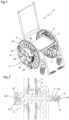
- THE figures 1 to 15 represent a motorization device 2 according to the present invention which is configured to be removably fixed to a wheel 3 of a manual wheelchair 4 and to rotate said wheel 3.
- each of the wheels 3 of the wheelchair manual 4 is equipped with a motorization device 2 according to the present invention.
- each wheel 3 comprises a wheel hub 5 mounted so as to be able to rotate around a respective wheel support shaft 6 which is immobile in rotation with respect to a frame 7 of the manual wheelchair 4.
- Each wheel support shaft 6 comprises a first end portion 6.1 which projects from an internal side of the respective wheel 3 and which is fixed to the frame 7, a second end portion 6.2 which projects from one side external of the respective wheel 3, and an intermediate portion 6.3 which connects the first and second end portions 6.1, 6.2 and which is configured to support the respective wheel hub 5 in rotation.
- the first end portion 6.1 of each wheel support shaft 6 is tapered and tapped, and is inserted into a cylindrical housing 8 provided on the frame 7.
- a part flexible 9 is interposed between the first end portion 6.1 and the cylindrical housing 8, and the first end portion 6.1 is fixed to the frame 7 by screwing a fixing screw 10 into the thread provided on the first end portion 6.1 .
- the fact of screwing the fixing screw 9 into the aforementioned thread induces a tightening of the flexible part 9 against the internal wall of the cylindrical housing 8, and therefore an angular blocking of the respective wheel support shaft 6.
- the motorization device 2 comprises a fixed mounting part 11 configured to be fixed to and to be immobilized in rotation with respect to the respective wheel support shaft 6, for example by means of fixing keys 12 provided on the second end portion 6.2 of the respective wheel support shaft 6.
- fixing keys 12 provided on the second end portion 6.2 of the respective wheel support shaft 6.
- Such fixing wedges 12 could however be replaced for example by a splined or multi-sided connection.
- the fixed mounting part 11 has the general shape of a disc and is provided with a first face oriented towards the respective wheel 3, and a second face oriented away from the first face. respectively.
- the fixed mounting part 11 comprises (see the figure 2 And 14 ) a dwelling of fixing 11.1 configured to cooperate with the second end portion 6.2 of the respective wheel support shaft 6 and with the fixing keys 12 provided on the latter, so as to immobilize the fixed mounting part 11 in rotation with respect to the respective wheel support shaft 6.
- the fixing housing 12 advantageously has a shape complementary to the second end portion 6.2 and the fixing keys 12.
- the motorization device 2 further comprises a rotary support part 13 which is mounted so as to be able to rotate with respect to the fixed mounting part 11 around an axis of rotation A which is configured to coincide with a longitudinal axis of the respective wheel support shaft 6 when the fixed mounting part 11 is fixed to said wheel support shaft 6.
- the rotary support part 13 comprises a support frame 14 which is generally annular and which extends around the axis of rotation A.
- the support frame 14 s extends coaxially with the axis of rotation A.
- the rotary support part 13 further comprises a cover cap 15 which is integral in rotation with the support frame 14 and which at least partially covers the support frame 14.
- the fixed mounting part 11 and the cover 15 form a motorization box and delimit an internal housing 16.
- the motorization device 2 further comprises a rotation drive mechanism 17 which is housed in the internal housing 16 and which is configured to drive the rotary support part 13 in rotation about the axis of rotation A.
- the rotary drive mechanism 17 comprises an electric motor 18 provided with a stator fixed to the fixed mounting part 11 and a rotor mounted so as to be able to rotate around the stator.
- the satellites 19.3 are distributed around the axis of rotation A and are respectively rotatably mounted on a connecting part 21 which is integral in rotation of the support frame 14, such that rotation of the rotor relative to the stator causes rotation of the rotatable support part 13 relative to the fixed mounting part 11.
- the motorization device 2 also comprises a control unit 22 configured to control the operation of the motorization device 2, and more particularly of the electric motor 18, and a supply battery 23 configured to electrically supply the motorization device 2, and in particular the control unit 22 and the electric motor 18.
- the control unit 22 and the supply battery 23 are housed in the internal housing 16.
- control unit 22 is provided with a microcontroller and can for example be configured to control the motorization device 2 from control signals coming from a smartphone (via for example a mobile application installed on the smartphone) or any other remote control system.
- the motorization device 2 could for example comprise a control lever, also called a joystick, configured to communicate remotely with the control unit 22 or even by wired communication.
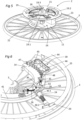
- the motorization device 2 further comprises several fixing arms 24 supported by the rotary support part 13 and distributed around the axis of rotation A.
- Each fixing arm 24 is mounted articulated on the rotary support part 13 about a respective hinge axis B which is substantially parallel to the axis of rotation A and between a fixing position in which said fixing arm 24 s extends radially with respect to the axis of rotation A and is configured to cooperate with a handrail 25 of the wheel 3 so as to transmit to the handrail 25 a torque generated by the rotation drive mechanism 17, and a release position in which said fixing arm 24 is inclined with respect to a radial direction and is configured to release the handrail 25 so as to allow removal of the fixed mounting part 11 from the wheel support shaft 6.
- the motorization device 2 comprises a plurality of biasing members 26, such as biasing springs, distributed around the axis of rotation A, and each biasing member 26 is configured to urge a respective fixing arm 24 towards the release position.
- Each biasing member 26 may for example comprise a first end portion fixed to the support frame 14 and a second end portion fixed to the fixing arm 24 respectively.
- the rotating support part 13 comprises abutment surfaces 27.1 and additional abutment surfaces 27.2 which are distributed around the axis of rotation A and which are provided on the support frame 14.
- Each fixing arm 24 is configured to abut against a respective abutment surface 27.1 when said attachment arm 24 reaches the attachment position, and each attachment arm 24 is configured to abut against a respective additional abutment surface 27.2 when said fixing arm 24 reaches the release position.
- each abutment surface 27.1 is configured to prevent pivoting of the respective attachment arm 24 beyond the attachment position
- each additional abutment surface 27.2 is configured to prevent pivoting of the respective attachment arm 24 beyond from the release position.
- Each fixing arm 24 is advantageously elastically deformable in a longitudinal direction of said fixing arm 24 between a retracted configuration (occupied by fixing arm 24 when it is in the fixing position) in which said fixing arm 24 has a first length and a deployed configuration (occupied by attachment arm 24 when in the release position) wherein said attachment arm 24 has a second length which is greater than the first length.
- each intermediate part 30 comprises a first arm part 30.1 fixed to the respective hinge part 28 (and for example mounted articulated with respect to the respective hinge part 28 around a axis which is perpendicular to the respective hinge axis B), a second arm part 30.2 fixed to the respective hooking part 29, and an elastic element 30.3, such as a compression spring, arranged between the first and second arm parts 30.1, 30.2 and configured to urge the second arm part 30.2 away from the first arm part 30.1, and therefore to elastically urge the respective attachment arm 24 towards the deployed configuration.
- an elastic element 30.3, such as a compression spring arranged between the first and second arm parts 30.1, 30.2 and configured to urge the second arm part 30.2 away from the first arm part 30.1, and therefore to elastically urge the respective attachment arm 24 towards the deployed configuration.
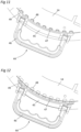
- each attachment part 29 has the general shape of a gutter, and advantageously has a cross section in the general shape of a C, a U or an Omega.
- Each attachment part 29 comprises a bottom portion and first and second lateral portions extending on either side of the respective bottom portion.
- the first and second lateral portions of each hooking part 29 are configured to extend respectively on either side of an extension plane in which the handrail 25 extends.
- attachment 29 prevents axial movement of the fixed mounting part 11 relative to the wheel support shaft 6 when each fixing arm 24 occupies the fixing position, and therefore prevents untimely dismantling of the motorization device 2.
- each hooking part 29 comprises a receiving housing 31 configured to house a part of the handrail 25 when the respective fixing arm 24 occupies the fixing position, and an introduction opening 32 which opens into the receiving housing 31 respective and which is configured to be oriented opposite the axis of rotation A when the respective fixing arm 24 occupies the fixing position.
- Each hooking part 29 comprises two longitudinal edges 33 which partly delimit the respective introduction opening 32 and which diverge opposite the respective receiving housing 31.
- the two longitudinal edges 33 are provided respectively on the respective first and second lateral portions.
- the first lateral portion of each hooking part 29 comprises an insertion notch 34 configured to facilitate insertion of the handrail 25 into the respective receiving housing 31 when the respective fixing arm 24 occupies the position of release.
- Each receiving housing 31 comprises a first housing portion 31.1 configured to receive a first handrail portion 25, when the respective fixing arm 24 occupies the release position and the fixed mounting part 11 is fixed to the wheel support 6, so as to allow pre-assembly of the motorization device 2 on the wheel 3, and a second housing portion 31.2 configured to receive a second handrail portion 25 when the respective fixing arm 24 occupies the position of fixation.
- the second housing portion 31.2 is curved and has a curvature substantially corresponding to the curvature of the handrail 25.
- each receiving housing 31 comprises an internal coating, for example of adhesive material, configured to promote adhesion between the respective hooking part 29 and the handrail 25 when the fixing arm 24 respectively occupies the fixing position.
- the motorization device 2 also comprises a locking mechanism 35 comprising a plurality of locking elements 36, such as locking pawls, distributed around the axis of rotation A.
- Each locking element 36 is pivotally mounted on the frame of support 14 about a respective pivot axis C which is parallel to the axis of rotation A and between a locking position (see the figure 9 ) in which said locking element 36 is configured to cooperate with a respective fixing arm 24 so as to lock the respective fixing arm 24 in the fixing position and an unlocking position (see figure 10 ) wherein said locking element 36 is configured to release the respective fixing arm 24 so as to allow movement of the respective fixing arm 24 between the release position and the fixing position.
- each fixing arm 24 comprises a locking housing 37, such as a locking notch, provided on the respective hinge part 28 and configured to receive the respective locking element 36 when said locking element 36 occupies the locking position. It should be noted that, when a fixing arm 24 occupies the release position, the respective locking element 36 is located outside the locking housing 37 provided on said fixing arm 24, and rests for example against a curved guide surface provided on said mounting arm 24.
- the locking mechanism 35 comprises a plurality of biasing elements 38 which are distributed around the axis of rotation A.
- Each biasing element 38 is configured to urge a respective locking element 36 towards the locking position.
- each biasing element 38 comprises a first end portion fixed to the support frame 14 and a second end portion fixed to the locking element 36 respectively.
- the motorization device 2 further comprises an actuation mechanism 39 which is mechanically coupled to the locking mechanism 35.
- the actuation mechanism 39 notably comprises an actuation part 41, such as an actuation crown, which is annular and which extends around the support frame 14 and coaxially with the axis of rotation A.
- the actuating part 41 comprises passage openings 42 distributed around the axis of rotation A, and each fixing arm 24 extends through a respective passage opening 42.
- the actuating part 41 is mounted so as to be able to rotate with respect to the rotary support part 13 around a central axis which is collinear with the axis of rotation A and according to a limited angular travel, and is configured to occupy in particular a first actuation position (see the figure 9 ) and a second actuation position (see figure 10 ).
- the actuating mechanism 39 and the locking mechanism 35 are configured such that a displacement of the actuating part 41 from the first actuating position to the second actuating position causes a simultaneous displacement of each element of locking 36 from the locking position to the unlocking position.
- the actuating mechanism 39 further comprises a plurality of actuating levers 43 distributed around the axis of rotation A, and each actuating lever 43 comprises a first end mounted articulated on the actuating part 41 and a second end hingedly mounted on a respective locking element 36.
- Each actuation lever 43 is configured to occupy a first lever position (see figure 9 ) and a second lever position (see figure 10 ).
- Actuation mechanism 39 is configured such that movement of actuation portion 41 from the first actuation position to the second actuation position actuation causes each actuating lever 43 to pivot from the first lever position to the second lever position and each locking element 36 to move from the locking position to the unlocking position.
- the actuating mechanism 39 also comprises a gripping device 44 which is mechanically connected to the actuating part 41 and which is configured to be manipulated by a user so as to move the actuating part 41 in particular between the first and second actuation positions.
- the gripping device 44 comprises a support body 45 integral in rotation with the actuating part 41 and configured to project through an opening provided on the actuating part 41.
- the gripping device 44 further comprises a gripping handle 46 which can for example be pivotally mounted on the support body 45 between a rest position and a gripping position.
- the gripping device 44 comprises a first coupling part 47, such as a first coupling toothing extending in an arc of a circle, provided on the support body 45 and configured to be located opposite a second coupling part 48, such as a second coupling toothing also extending in an arc of a circle, provided on the support frame 14 when the actuating part 41 occupies the second actuating position.
- a first coupling part 47 such as a first coupling toothing extending in an arc of a circle
- second coupling part 48 such as a second coupling toothing also extending in an arc of a circle
- the gripping device 44 can be moved radially with respect to the actuating part 41 between an uncoupling position (see the figure 12 ) in which the first coupling part 47 is located at a distance from the second coupling part 48 so as to allow, when each fixing arm 24 occupies the fixing position, a relative movement of the actuating part 41 by relative to the rotating support part 13, and a coupling position (see the figure 11 ) in which the first coupling part 47 is coupled with the second coupling part 48 so as to secure in rotation the actuating part 41 and the rotary support part 13.
- an uncoupling position see the figure 12
- the first coupling part 47 is located at a distance from the second coupling part 48 so as to allow, when each fixing arm 24 occupies the fixing position, a relative movement of the actuating part 41 by relative to the rotating support part 13, and a coupling position (see the figure 11 ) in which the first coupling part 47 is coupled with the second coupling part 48 so as to secure in rotation the actuating part 41 and the rotary support part 13.
- the actuating mechanism 39 comprises a return member (not visible in the figures) configured to urge the gripping device 44 towards the uncoupling position
- the support body 45 comprises a retaining surface 49 configured to come into abutment against an internal surface of the part actuation 41 when the gripping device 44 occupies the uncoupling position.
- the actuating mechanism 39 and the rotary support part 13 are more particularly configured such that, when the gripping device 44 occupies the coupling position, each fixing arm 24 occupies the fixing position and cooperates with the handrail 25 and a torque is applied by a user to the actuating part 41 via the gripping device 44 and around the axis of rotation A, each arm fixing 24 is then moved to the release position, due to the rotation of the support frame 14 and the actuating part 41 around the axis of rotation A.
- the respective locking element 36 can for example abut against an abutment surface provided on the support frame 14, so that that a rotational movement of the actuating part 41 in a direction of rotation having the consequence of biasing the locking element 36 against said respective abutment surface also causes a rotation of the support frame 14 in the same direction of rotation (The actuating part 41 and the support frame 14 are then integral in rotation).
- a rotational movement of the actuating part 41 in a direction of rotation having the consequence of biasing the locking element 36 remote from the respective locking housing 37 comprises a first displacement phase during which the actuating part 41 is driven in rotation with respect to the support frame 14 until the locking element 36 comes into abutment against the respective abutment surface provided on the support frame 14, and a second movement phase during which the actuating part 41 and the support frame 14 are integral in rotation and the support frame 14 urges the fixing arm respective to the fixing position.
- the second actuating position of the actuating part 41 corresponds to a position in which each locking element 36 is in abutment against the respective abutment surface provided on the support frame 14.
- each fixing arm 24 When a fixing arm 24 reaches the fixing position, the respective locking element 36 is located opposite the locking housing 37 provided on said fixing arm 24 and is urged towards the locking position by the biasing element 38 respectively. In such a fixing position, each fixing arm 24 is on the one hand in abutment against the respective abutment surface 27.1 provided on the support frame 14, and is on the other hand blocked by the locking element 36, making impossible any pivoting of the support arm 14 around its axis of articulation B.
- the motorization device 2 can be easily mounted on a manual wheelchair 4 so as to motorize the latter, and can also be easily removed from the manual wheelchair 4 to allow manual use of the latter.
Landscapes
- Health & Medical Sciences (AREA)
- Life Sciences & Earth Sciences (AREA)
- Animal Behavior & Ethology (AREA)
- General Health & Medical Sciences (AREA)
- Public Health (AREA)
- Veterinary Medicine (AREA)
- Mechanical Control Devices (AREA)
- Electric Propulsion And Braking For Vehicles (AREA)
- Invalid Beds And Related Equipment (AREA)
Applications Claiming Priority (1)
| Application Number | Priority Date | Filing Date | Title |
|---|---|---|---|
| FR2201459A FR3132838B1 (fr) | 2022-02-18 | 2022-02-18 | Dispositif de motorisation pour fauteuil roulant manuel |
Publications (1)
| Publication Number | Publication Date |
|---|---|
| EP4230182A1 true EP4230182A1 (de) | 2023-08-23 |
Family
ID=82100416
Family Applications (1)
| Application Number | Title | Priority Date | Filing Date |
|---|---|---|---|
| EP23157046.6A Withdrawn EP4230182A1 (de) | 2022-02-18 | 2023-02-16 | Motorisierungsvorrichtung für einen manuellen rollstuhl |
Country Status (2)
| Country | Link |
|---|---|
| EP (1) | EP4230182A1 (de) |
| FR (1) | FR3132838B1 (de) |
Citations (5)
| Publication number | Priority date | Publication date | Assignee | Title |
|---|---|---|---|---|
| US20100300777A1 (en) | 2009-05-27 | 2010-12-02 | Beach Mobility, Inc. | Power Add-On Device For Manual Wheelchair |
| US20110187074A1 (en) * | 2006-10-16 | 2011-08-04 | Andrew Malloy | Propulsion apparatus |
| ES2386714B1 (es) | 2011-02-01 | 2013-07-08 | Georges Henri Claude PEDARRIBES | Kit de motorización de sillas de ruedas. |
| KR101385571B1 (ko) * | 2013-03-06 | 2014-04-15 | 근로복지공단 | 전동보조형 휠체어용 구동장치 |
| US20140183930A1 (en) * | 2012-12-27 | 2014-07-03 | Industrial Technology Research Institute | Detachable power module |
-
2022
- 2022-02-18 FR FR2201459A patent/FR3132838B1/fr active Active
-
2023
- 2023-02-16 EP EP23157046.6A patent/EP4230182A1/de not_active Withdrawn
Patent Citations (5)
| Publication number | Priority date | Publication date | Assignee | Title |
|---|---|---|---|---|
| US20110187074A1 (en) * | 2006-10-16 | 2011-08-04 | Andrew Malloy | Propulsion apparatus |
| US20100300777A1 (en) | 2009-05-27 | 2010-12-02 | Beach Mobility, Inc. | Power Add-On Device For Manual Wheelchair |
| ES2386714B1 (es) | 2011-02-01 | 2013-07-08 | Georges Henri Claude PEDARRIBES | Kit de motorización de sillas de ruedas. |
| US20140183930A1 (en) * | 2012-12-27 | 2014-07-03 | Industrial Technology Research Institute | Detachable power module |
| KR101385571B1 (ko) * | 2013-03-06 | 2014-04-15 | 근로복지공단 | 전동보조형 휠체어용 구동장치 |
Also Published As
| Publication number | Publication date |
|---|---|
| FR3132838A1 (fr) | 2023-08-25 |
| FR3132838B1 (fr) | 2024-03-01 |
Similar Documents
| Publication | Publication Date | Title |
|---|---|---|
| EP3405633B1 (de) | Externe öffnungssteuerung eines kraftfahrzeugs | |
| EP0694434B1 (de) | Gelenkbeschlag für Fahrzeugsitz | |
| EP0705727B1 (de) | Gelenkebeschlag für eine Fahrzeugsitzrückenlehne | |
| EP3404177B1 (de) | Steuermechanismus eines flächenbündigen griffs | |
| EP0430794B1 (de) | Demontierbarer Rollstuhl und Tasche zum Transport eines solchen Stuhles nach seiner Demontage | |
| FR2743764A1 (fr) | Mecanisme d'articulation pour siege de vehicule, et siege comportant un tel mecanisme | |
| EP3404176B1 (de) | Vorrichtung zum entriegeln eines türschlosses | |
| EP0806531A1 (de) | Axial (ent)kuppelndes Schloss für ein Schlossmechanismus eines Personenkraftwagens | |
| FR2822419A1 (fr) | Siege de vehicule equipe d'un mecanisme d'articulation | |
| EP3458662B1 (de) | Steuerung einer externen öffnung eines kraftfahrzeugs | |
| CA3042195C (fr) | Dispositif de verrouillage a verrou rotatif a commande impulsionnelle | |
| FR2972972A1 (fr) | Systeme d'articulation et siege de vehicule comportant un tel systeme d'articulation | |
| FR2724431A1 (fr) | Moyeu a roue libre pour cycles | |
| FR2846570A1 (fr) | Vehicule jouet | |
| FR2792583A1 (fr) | Mecanisme d'articulation pour siege de vehicule | |
| FR2841838A1 (fr) | Siege de vehicule equipe d'un mecanisme d'articulation | |
| FR2876761A1 (fr) | Systeme de moyeu pour bicyclette | |
| WO2003083243A9 (fr) | Mecanisme de tension d'un ressort de compensation pour installation de fermeture ou de protection solaire | |
| EP4230182A1 (de) | Motorisierungsvorrichtung für einen manuellen rollstuhl | |
| EP1994243B1 (de) | Selbstausrückendes schloss für autoschlossmechanismus | |
| EP0943758A1 (de) | Axial entkuppelndes Schloss für ein Schlossmechanismus eines Personenkraftwagens | |
| WO2023002016A1 (fr) | Volant de vehicule comprenant des mecanismes et un actionneur de commande | |
| EP3920862B1 (de) | Elektrische hilfsvorrichtung | |
| FR2480206A1 (fr) | Vehicule automobile equipe d'un siege pivotant pour handicape | |
| EP1640555B1 (de) | Drive with automatic clutch for a building closure |
Legal Events
| Date | Code | Title | Description |
|---|---|---|---|
| PUAI | Public reference made under article 153(3) epc to a published international application that has entered the european phase |
Free format text: ORIGINAL CODE: 0009012 |
|
| STAA | Information on the status of an ep patent application or granted ep patent |
Free format text: STATUS: THE APPLICATION HAS BEEN PUBLISHED |
|
| AK | Designated contracting states |
Kind code of ref document: A1 Designated state(s): AL AT BE BG CH CY CZ DE DK EE ES FI FR GB GR HR HU IE IS IT LI LT LU LV MC ME MK MT NL NO PL PT RO RS SE SI SK SM TR |
|
| STAA | Information on the status of an ep patent application or granted ep patent |
Free format text: STATUS: THE APPLICATION IS DEEMED TO BE WITHDRAWN |
|
| 18D | Application deemed to be withdrawn |
Effective date: 20240224 |