EP2476528A1 - Mater aus festem oder halbfestem Material, und Aussparungsgehäuse, das durch das Biegen dieser Mater entsteht - Google Patents
Mater aus festem oder halbfestem Material, und Aussparungsgehäuse, das durch das Biegen dieser Mater entsteht Download PDFInfo
- Publication number
- EP2476528A1 EP2476528A1 EP11360052A EP11360052A EP2476528A1 EP 2476528 A1 EP2476528 A1 EP 2476528A1 EP 11360052 A EP11360052 A EP 11360052A EP 11360052 A EP11360052 A EP 11360052A EP 2476528 A1 EP2476528 A1 EP 2476528A1
- Authority
- EP
- European Patent Office
- Prior art keywords
- width
- strips
- reservation box
- folding
- mutual cooperation
- Prior art date
- Legal status (The legal status is an assumption and is not a legal conclusion. Google has not performed a legal analysis and makes no representation as to the accuracy of the status listed.)
- Withdrawn
Links
Images


Classifications
-
- B—PERFORMING OPERATIONS; TRANSPORTING
- B28—WORKING CEMENT, CLAY, OR STONE
- B28B—SHAPING CLAY OR OTHER CERAMIC COMPOSITIONS; SHAPING SLAG; SHAPING MIXTURES CONTAINING CEMENTITIOUS MATERIAL, e.g. PLASTER
- B28B23/00—Arrangements specially adapted for the production of shaped articles with elements wholly or partly embedded in the moulding material; Production of reinforced objects
- B28B23/0068—Embedding lost cores
-
- E—FIXED CONSTRUCTIONS
- E04—BUILDING
- E04G—SCAFFOLDING; FORMS; SHUTTERING; BUILDING IMPLEMENTS OR AIDS, OR THEIR USE; HANDLING BUILDING MATERIALS ON THE SITE; REPAIRING, BREAKING-UP OR OTHER WORK ON EXISTING BUILDINGS
- E04G15/00—Forms or shutterings for making openings, cavities, slits, or channels
- E04G15/06—Forms or shutterings for making openings, cavities, slits, or channels for cavities or channels in walls of floors, e.g. for making chimneys
- E04G15/061—Non-reusable forms
-
- E—FIXED CONSTRUCTIONS
- E04—BUILDING
- E04G—SCAFFOLDING; FORMS; SHUTTERING; BUILDING IMPLEMENTS OR AIDS, OR THEIR USE; HANDLING BUILDING MATERIALS ON THE SITE; REPAIRING, BREAKING-UP OR OTHER WORK ON EXISTING BUILDINGS
- E04G21/00—Preparing, conveying, or working-up building materials or building elements in situ; Other devices or measures for constructional work
- E04G21/32—Safety or protective measures for persons during the construction of buildings
- E04G21/3204—Safety or protective measures for persons during the construction of buildings against falling down
- E04G21/3223—Means supported by building floors or flat roofs, e.g. safety railings
-
- E—FIXED CONSTRUCTIONS
- E04—BUILDING
- E04G—SCAFFOLDING; FORMS; SHUTTERING; BUILDING IMPLEMENTS OR AIDS, OR THEIR USE; HANDLING BUILDING MATERIALS ON THE SITE; REPAIRING, BREAKING-UP OR OTHER WORK ON EXISTING BUILDINGS
- E04G9/00—Forming or shuttering elements for general use
- E04G9/08—Forming boards or similar elements, which are collapsible, foldable, or able to be rolled up
- E04G9/083—Forming boards or similar elements, which are collapsible, foldable, or able to be rolled up which are foldable
Definitions
- the present invention relates to a blank of rigid or semi-rigid material, arranged to form after folding a reservation box intended to be integrated into a building element such as a floor made from a predalle, said blank comprising a central panel, intended to form the bottom of said reservation box, and peripheral panels each connected to said central panel by a main folding line and intended to form at least the side walls of said reservation box, said peripheral panels comprising mutual cooperation means for shaping said sidewalls.
- the present invention also relates to a reservation box comprising peripheral walls connected to a bottom, intended to be integrated into a construction element such as a floor made from a predalle, said box being obtained by folding a blank of rigid or semi-rigid material as described above.
- the reservation boxes serve as formwork elements to provide, in the floors to which they are integrated, reservations for the subsequent passage of ducts, pipes, pipes or other.
- the present invention relates more specifically to the field of the realization of reservations in floors designed from factory pre-fabricated reinforced concrete slabs then transported to the site and intended to serve both as floor formwork and to constitute the part thereof. lower.
- the first step consisting of forming first reservations in the pre-slats during their manufacture in the factory, is conventionally carried out using first frames made to measure using rules of metal, corrugated board or polystyrene, glued or magnetized on the metal formwork tables.
- the second step is to set up second reservations at the site, in the concrete slab cast on site, as an extension of the first reservations, by means of second frames made to measure as previously by the workers responsible for the floor.
- the reservations made by this technique constitute, at least temporarily, holes through the floor from top to bottom, and presenting a significant danger for the teams then evolving on the site.
- the risk of falling tools or even falls from man through high dimensional reservations difficult to secure, are particularly to be feared.
- the present invention aims to overcome these disadvantages by proposing an optimized solution to not only eliminate any danger and any risk of falling man or object through a reservation, but also to get rid of the formwork operations on site .
- Another object of the present invention is to provide an environmentally friendly solution, avoiding the production of waste that is difficult to recycle.
- the invention relates to a blank of rigid or semi-rigid material of the type indicated in the preamble, characterized in that said peripheral panels each comprise a secondary fold line, parallel to the main fold line, delimiting on each side between them a first band of width x and a second band of width y , said bands of width x and said bands of width being arranged therein to form, in a first state of folding of said blank, the side walls of a box of reservation closed by a cover, of height x intended to be at least equal to the thickness of said predalle and, in a second folded state of said blank, the side walls of an open reservation box of height x + y intended for be substantially equal to the thickness of said floor.
- said mutual cooperation means comprise first mutual cooperation means arranged to allow the assembly of said strips of width x in said first and second folding states of said blank, and second mutual cooperation means arranged to allow said strips of width y to be joined together in said second folding state of said blank.
- said first means of mutual cooperation are formed on said bands of widths x , while said second mutual cooperation means are provided on said strips of width y .
- said mutual cooperation means may also comprise third mutual cooperation means associated with said strips of width y to maintain them in closed position and form said cover of said closed reservation box in said first folding state of said blank.
- said mutual cooperation means respectively comprise tabs and slots arranged to receive said tabs.
- each peripheral panel has at least one orifice, preferably in its width x band , arranged to be aligned with an orifice of another opposite peripheral panel and intended to forming with this orifice a passage for receiving a rod passing through said reservation box, said rod possibly being constituted by a metal reinforcement of said predalle or by a rod specifically dedicated to the desired effect.
- the blank according to the invention is made of a material selected from the group consisting of a synthetic material, a composite material, cardboard, a combination of these materials.
- the present invention also relates to a reservation box of the kind indicated in the preamble and obtained by folding a blank as described above.
- the invention relates to a blank 1 made of a rigid or semi-rigid material, arranged to form after folding a reservation box 2 intended to be integrated in a floor 3 made from a predalle 4 classically constituted a reinforcement panel arranged in the form of a mesh 501 embedded in a concrete layer 40, and stiffening elements in the form of generally three-dimensional metal mesh 502 embedded in their lower part in the concrete of the pre-slab 40, and emerging in the top part.
- the material envisaged for producing such a blank 1 may be a synthetic material, a composite material, cardboard or any other material having similar properties, or a combination of these materials, in the form of cellular honeycomb sheets, corrugated, honeycomb , streaked or full.
- the blank 1 comprises a central panel 10, to which are connected, by means of a main fold line 5 extending along the edges of said central panel 10, two pairs of peripheral panels 11, 12.
- the central panel 10 and the two pairs of peripheral panels 11, 12 are intended to form respectively the bottom 20, the side walls 21, 22 and the cover 23 of a reservation box 2.
- the central panel 10 has a quadrilateral shape, other shapes could also be envisaged, such as in particular any other polygonal shape having a number of sides greater than three.
- the peripheral panels 11, 12 of the same pair are identical to each other and connected to opposite external edges of the central panel 10.
- they each comprise a secondary fold line 110 , 120, parallel to the main fold line 5, and delimiting on each of them a first band 111, 121 of width x and a second band 112, 122 of width y .
- the widths x and y are chosen so as to be substantially equal respectively to the thickness of the pre-slab 4 and the thickness of the concrete slab 41 cast on the slab 4 to manufacture the floor 3 (cf. Fig. 8 ).
- the peripheral panels 11, 12 further comprise at least one orifice 60 located at the strips 111, 121 of width x and whose role will be detailed later.
- the peripheral panels 11, 12 also comprise means of mutual cooperation, such as for example tabs 6, 8 and slots 7, 9 arranged respectively to accommodate said tabs 6, 8 and allowing the shaping of said side walls 21, 22 for the manufacture of the reservation box 2.
- mutual cooperation means of different shape and / or differently arranged could also be considered.
- the tongues 6 and the slots 7 are formed respectively at the bands 121, 111 of width x while the tongues 8 and the slots 9 are formed respectively at the level of the strips 122, 112 of width y of the peripheral panels 12 and 11.
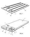
- Such a blank 1 can therefore be folded in two different ways leading for one to a closed state (cf. Fig. 5 and 6 ) and for the other to an open state of the reservation box 2 (cf. Fig. 2 to 4 , 7 and 8 ).
- the first folding state of the blank 1 is obtained by first rotating the peripheral panels 11, 12 at an angle of about 90 ° around the main fold line 5 so as to arrange them in planes perpendicular to the panel central 10. Then, the strips 111, 121 of width x of the peripheral panels 11, 12 are assembled together by inserting the tongues 6 in the slots 7, while the strips 112, 122 of width are folded by pivoting a y an angle of about 90 ° around the secondary fold lines 110, 120 in the direction of the central panel 10 to form a lid 23.
- This provides a reservation box 2 closed by a lid 23 defined by the strips 112, 122 of width y , and having side walls 21, 22 defined by the strips 111, 121 of width x , said box therefore having a height x at least equal and preferably slightly greater than the thickness of the predalle 4 (cf. Fig. 5 and 6 ).
- the strips 112, 122 of width are preferably kept in closed position by third means for mutual cooperation (not shown), for example of the type comprising tabs and slots, or simply with adhesive tape or by any other equivalent means.
- the orifices 60 of the two side walls 21 facing each other and the two side walls 22 facing each other constitute two-by-two passages for metal rods or made of any other material of comparable characteristics 51 passing through the reservation box 2, these rods advantageously forming between them a reinforcing grid located above the bottom of said reservation box 2 or forming an integral part of the metal frame 501 of the predalle 4 .
- the reservation box 2 can be integrated in a predalle 4 ( Fig. 5 ) before the pouring of the concrete layer 40
- a tubular sleeve (not shown) complementary shape introduced into the opening of the reservation box 2 and for extending from a height equal to that of said sleeve, said side walls 21, 22.
- the metal rods 51 passing through the reservation box 2 from one end to the other and properly anchored in the pre-slab concrete 40 withstand the weight of a person inadvertently placing the foot inside the reservation.
- These rods advantageously constitute a mesh whose dimensions prevent the fall of a person through said reservation.
- the reservation box 2 whether in its closed state or in its open state is a visible element by the operator contributing to its security, and is closed by a bottom preventing the falling of objects through.
- the reservation zones are therefore completely secure during the various work phases and during that in which the bottom of the reservation box 2 is open to allow the passage of the technical sleeves and others. defining the thickness of the predalle 4.
- the metal rods 51 passing through the reservation box 2 are anchored in the thickness of the precast concrete 4, sufficiently to be able to ensure the diffusion of the expected forces to the load-bearing structure of the predalle. Since the side walls 21, 22 of the closed reservation box 2 have a height x substantially greater than the thickness of the predalle 4, the cover 23 of said reservation box 2 is at a level between the upper surface of the the predalle 4 and the top of the metal frame 502 when the manufacture thereof is completed.
- Such a configuration advantageously allows the layers 4 to be superimposed in order to facilitate their storage and transport, without the risk of damaging the reservation boxes 2 which are integrated therein.
- the reservation box 2 can be opened by unfolding the strips 112, 122 of width y by pivoting at an angle of about 90 ° around the secondary fold lines 110. 120 so as to separate them from the central panel 10 and to dispose respectively in the extension of the strips 111, 121 of width x (cf. Fig. 7 ).
- the strips 112, 122 of width are maintained are assembled together by inserting the tongues 8 into the slots 9.
- the reservation box 2 therefore includes sidewalls 21, 22 of height equal to x + y corresponding to the thickness of the predalle 4 added to that of the additional thickness of concrete poured on site 41, and intended to form the upper part of the floor.
- the latter can therefore be cast on said floor 4 for the manufacture of the floor 3 without requiring the establishment of additional formwork (cf. fig.8 ).
- additional formwork cf. fig.8
- interlayers inside the box 2 allowing the side walls 21, 22 to stay parallel.
- These intermediate parts may be wooden rafters substantially equal in size to those of the sides of the rectangular box, and placed so as to reinforce the walls located opposite each other, thus functioning as bumpers.
- the reservation box 2 is easy to implement.
- its bottom can be cut with precision, for example using a tool such as a cutter, so as to remove only the material hindering for the passage of technical ducts and others that must be introduced to through the reservation.
- the residual portion of the bottom can also be used as formwork in the underside of floor 3 to recycle concrete to reconstruct a possible firebreak or the acoustic properties of the floor 3.
- the reservation box according to the present invention remains in place, embedded in the concrete of the floor 3, without generating any waste, which makes it perfectly respectful of the environment.
Landscapes
- Engineering & Computer Science (AREA)
- Architecture (AREA)
- Mechanical Engineering (AREA)
- Civil Engineering (AREA)
- Structural Engineering (AREA)
- Manufacturing & Machinery (AREA)
- Chemical & Material Sciences (AREA)
- Ceramic Engineering (AREA)
- Packaging Of Annular Or Rod-Shaped Articles, Wearing Apparel, Cassettes, Or The Like (AREA)
- Building Environments (AREA)
Applications Claiming Priority (1)
| Application Number | Priority Date | Filing Date | Title |
|---|---|---|---|
| FR1150343A FR2970469B1 (fr) | 2011-01-17 | 2011-01-17 | Flan de matiere rigide ou semi-rigide et boite de reservation obtenue par pliage dudit flan |
Publications (1)
| Publication Number | Publication Date |
|---|---|
| EP2476528A1 true EP2476528A1 (de) | 2012-07-18 |
Family
ID=44169014
Family Applications (1)
| Application Number | Title | Priority Date | Filing Date |
|---|---|---|---|
| EP11360052A Withdrawn EP2476528A1 (de) | 2011-01-17 | 2011-11-22 | Mater aus festem oder halbfestem Material, und Aussparungsgehäuse, das durch das Biegen dieser Mater entsteht |
Country Status (2)
| Country | Link |
|---|---|
| EP (1) | EP2476528A1 (de) |
| FR (1) | FR2970469B1 (de) |
Cited By (2)
| Publication number | Priority date | Publication date | Assignee | Title |
|---|---|---|---|---|
| FR3051808A1 (fr) * | 2016-05-27 | 2017-12-01 | Kp1 | Predalle comprenant au moins une incorporation et procede de fabrication d’un plancher a l’aide d’une telle predalle |
| EP3249128A3 (de) * | 2016-05-27 | 2018-02-28 | Kp1 | Elementplatte mit anzeigemitteln der kanalverläufe, und entsprechendes herstellungsverfahren |
Citations (6)
| Publication number | Priority date | Publication date | Assignee | Title |
|---|---|---|---|---|
| US2192183A (en) * | 1937-05-27 | 1940-03-05 | Deutsch Maurice | Method of making concrete slabs |
| US3358960A (en) * | 1965-10-21 | 1967-12-19 | Connelly Containers Inc | Core insert for concrete structures |
| US4101052A (en) * | 1977-03-04 | 1978-07-18 | Interstore Transfer Specialists, Inc. | Containers for transferring merchandise between distribution service centers and retail stores, while security sealed in either an expanded or a reduced volume configuration |
| US4272009A (en) * | 1979-10-31 | 1981-06-09 | Manville Forest Products | One-piece double depth shipping container |
| US4986217A (en) * | 1989-09-15 | 1991-01-22 | Robinson Hartman | Disposable cat litter box |
| US20060081690A1 (en) * | 2004-09-01 | 2006-04-20 | Aaron Bates | Carton and blank for expandable carton |
-
2011
- 2011-01-17 FR FR1150343A patent/FR2970469B1/fr not_active Expired - Fee Related
- 2011-11-22 EP EP11360052A patent/EP2476528A1/de not_active Withdrawn
Patent Citations (6)
| Publication number | Priority date | Publication date | Assignee | Title |
|---|---|---|---|---|
| US2192183A (en) * | 1937-05-27 | 1940-03-05 | Deutsch Maurice | Method of making concrete slabs |
| US3358960A (en) * | 1965-10-21 | 1967-12-19 | Connelly Containers Inc | Core insert for concrete structures |
| US4101052A (en) * | 1977-03-04 | 1978-07-18 | Interstore Transfer Specialists, Inc. | Containers for transferring merchandise between distribution service centers and retail stores, while security sealed in either an expanded or a reduced volume configuration |
| US4272009A (en) * | 1979-10-31 | 1981-06-09 | Manville Forest Products | One-piece double depth shipping container |
| US4986217A (en) * | 1989-09-15 | 1991-01-22 | Robinson Hartman | Disposable cat litter box |
| US20060081690A1 (en) * | 2004-09-01 | 2006-04-20 | Aaron Bates | Carton and blank for expandable carton |
Cited By (3)
| Publication number | Priority date | Publication date | Assignee | Title |
|---|---|---|---|---|
| FR3051808A1 (fr) * | 2016-05-27 | 2017-12-01 | Kp1 | Predalle comprenant au moins une incorporation et procede de fabrication d’un plancher a l’aide d’une telle predalle |
| EP3249127A3 (de) * | 2016-05-27 | 2018-02-28 | Kp1 | Elementplatte, die mindestens ein einbauelement enthält, und herstellungsverfahren einer decke mithilfe dieser elementplatte |
| EP3249128A3 (de) * | 2016-05-27 | 2018-02-28 | Kp1 | Elementplatte mit anzeigemitteln der kanalverläufe, und entsprechendes herstellungsverfahren |
Also Published As
| Publication number | Publication date |
|---|---|
| FR2970469B1 (fr) | 2014-03-21 |
| FR2970469A1 (fr) | 2012-07-20 |
Similar Documents
| Publication | Publication Date | Title |
|---|---|---|
| FR3013371A1 (fr) | Boite de reservation pour murs ou dalles de beton | |
| EP2211000A1 (de) | Schaltafel für eine Betonmauer | |
| EP2792806B1 (de) | Vorgefertigte platte mit unterbrochener wärmebrücke, ihr herstellungsverfahren und baumethode einer decke mit einer solchen platte | |
| EP2474400B1 (de) | Aussparungsgehäuse und Verfahren zur Herstellung | |
| FR2990714A1 (fr) | Boite de guidage d'une coulee de beton, realisee en materiau alveolaire, et ensemble de boites pour construction en beton | |
| FR2970469A1 (fr) | Flan de matiere rigide ou semi-rigide et boite de reservation obtenue par pliage dudit flan | |
| EP2069585B1 (de) | Verkleidungsplatte, insbesondere Gipskartonplatte | |
| WO2000031355A1 (fr) | Element de coffrage perdu, entrevous et tympan faisant application | |
| FR2991704A1 (fr) | Coffrage d'ouverture | |
| FR2609965A1 (fr) | Emballage du genre caisse, en particulier caisse a legumes en carton, carton ondule ou autre materiau en feuille | |
| EP1067254B1 (de) | Haube eines Bewehrungsanschlusskastens und Bewehrungsanschlusskasten mit einer solchen Haube | |
| EP2085538B1 (de) | Modulare Treppe, die mindestens mit einem Profil ausgestattet ist, das eine Treppenkante bildet | |
| EP3058150B1 (de) | Konstruktionsmodul aus karton und herstellungsmethode hierfür | |
| FR2918091A1 (fr) | Boite de reservation d'un espace creux, notamment dans une dalle en beton | |
| FR3077832A1 (fr) | Boite de reservation pour un plancher et procede de fabrication d'un plancher pourvu d'une reservation traversante | |
| EP3894643A1 (de) | Vorrichtung zur unterstützung der glättung einer beschichtung | |
| EP2009200A1 (de) | Aussparungsgehäuse für Hohlraum, insbesondere in einer Betonplatte | |
| FR2861767A1 (fr) | Rupteur thermique pour plancher en beton, dalle prefabriquee equipee d'un tel rupteur thermique et procede de fabrication d'un plancher | |
| FR3030590A1 (fr) | Systeme et procede de construction d'un mur a entretoise | |
| EP2843156B1 (de) | Verteilerkasten und Montageverfahren zum Einbau eines solchen Kastens | |
| BE1017285A3 (fr) | Entrevous isolant pour plancher a poutrelles et plancher obtenu. | |
| EP1559654A1 (de) | Behälter aus einem faltbaren Film | |
| EP1538273A1 (de) | Vorgefertigtes verlorenes Schalungelement, mit diesem Schalungselement hergestelltes Modul und aus solchen Modulen hergestellte Struktur | |
| WO2014102266A1 (fr) | Kit de banchage pour la construction d'un mur avec integration du kit, ainsi que procede de construction d'un mur utilisant un tel kit | |
| EP3406803A1 (de) | Vorgefertigte all-in-one-einheit eines faltkastens |
Legal Events
| Date | Code | Title | Description |
|---|---|---|---|
| PUAI | Public reference made under article 153(3) epc to a published international application that has entered the european phase |
Free format text: ORIGINAL CODE: 0009012 |
|
| AK | Designated contracting states |
Kind code of ref document: A1 Designated state(s): AL AT BE BG CH CY CZ DE DK EE ES FI FR GB GR HR HU IE IS IT LI LT LU LV MC MK MT NL NO PL PT RO RS SE SI SK SM TR |
|
| AX | Request for extension of the european patent |
Extension state: BA ME |
|
| STAA | Information on the status of an ep patent application or granted ep patent |
Free format text: STATUS: THE APPLICATION IS DEEMED TO BE WITHDRAWN |
|
| 18D | Application deemed to be withdrawn |
Effective date: 20130119 |