EP2476563A2 - Vollreifen - Google Patents
Vollreifen Download PDFInfo
- Publication number
- EP2476563A2 EP2476563A2 EP12150123A EP12150123A EP2476563A2 EP 2476563 A2 EP2476563 A2 EP 2476563A2 EP 12150123 A EP12150123 A EP 12150123A EP 12150123 A EP12150123 A EP 12150123A EP 2476563 A2 EP2476563 A2 EP 2476563A2
- Authority
- EP
- European Patent Office
- Prior art keywords
- solid tire
- tire
- solid
- plastic
- rim
- Prior art date
- Legal status (The legal status is an assumption and is not a legal conclusion. Google has not performed a legal analysis and makes no representation as to the accuracy of the status listed.)
- Granted
Links
Images


Classifications
-
- B—PERFORMING OPERATIONS; TRANSPORTING
- B60—VEHICLES IN GENERAL
- B60C—VEHICLE TYRES; TYRE INFLATION; TYRE CHANGING; CONNECTING VALVES TO INFLATABLE ELASTIC BODIES IN GENERAL; DEVICES OR ARRANGEMENTS RELATED TO TYRES
- B60C7/00—Non-inflatable or solid tyres
- B60C7/10—Non-inflatable or solid tyres characterised by means for increasing resiliency
- B60C7/101—Tyre casings enclosing a distinct core, e.g. foam
- B60C7/1015—Tyre casings enclosing a distinct core, e.g. foam using foam material
-
- B—PERFORMING OPERATIONS; TRANSPORTING
- B60—VEHICLES IN GENERAL
- B60C—VEHICLE TYRES; TYRE INFLATION; TYRE CHANGING; CONNECTING VALVES TO INFLATABLE ELASTIC BODIES IN GENERAL; DEVICES OR ARRANGEMENTS RELATED TO TYRES
- B60C7/00—Non-inflatable or solid tyres
- B60C7/10—Non-inflatable or solid tyres characterised by means for increasing resiliency
- B60C7/12—Non-inflatable or solid tyres characterised by means for increasing resiliency using enclosed chambers, e.g. gas-filled
- B60C7/121—Non-inflatable or solid tyres characterised by means for increasing resiliency using enclosed chambers, e.g. gas-filled enclosed chambers defined by a distinct core
-
- B—PERFORMING OPERATIONS; TRANSPORTING
- B60—VEHICLES IN GENERAL
- B60C—VEHICLE TYRES; TYRE INFLATION; TYRE CHANGING; CONNECTING VALVES TO INFLATABLE ELASTIC BODIES IN GENERAL; DEVICES OR ARRANGEMENTS RELATED TO TYRES
- B60C7/00—Non-inflatable or solid tyres
- B60C7/22—Non-inflatable or solid tyres having inlays other than for increasing resiliency, e.g. for armouring
-
- B—PERFORMING OPERATIONS; TRANSPORTING
- B60—VEHICLES IN GENERAL
- B60C—VEHICLE TYRES; TYRE INFLATION; TYRE CHANGING; CONNECTING VALVES TO INFLATABLE ELASTIC BODIES IN GENERAL; DEVICES OR ARRANGEMENTS RELATED TO TYRES
- B60C9/00—Reinforcements or ply arrangement of pneumatic tyres
- B60C9/02—Carcasses
- B60C9/14—Carcasses built-up with sheets, webs, or films of homogeneous material, e.g. synthetics, sheet metal, rubber
Definitions
- the invention relates to a solid tire for small vehicles with a profiled tread and a tire sidewall.
- Solid tires For small vehicles such as in particular wheelbarrows, golf caddies, baby carriages or the like solid tires are known, which have a profiled tread and a standing in contact with the rim rim. Solid tires have the advantage of higher robustness compared to conventional pneumatic tires.
- solid tire in this context refers to more or less massive tires, which, unlike pneumatic tires, do not contain pressurized air or other pressurized gases, but derive their shock-absorbing or resilient properties due to their manufacture from a more or less elastic material.
- common solid tires for wheelbarrows have the dimensions 400 x 100 mm and 350 x 100 mm.
- the bearing surface on the ground is thus determined by the width of 100 mm.
- these tires have a semicircular tread.
- this expresses itself easily in soft surfaces. Driving on soft ground is made much more difficult.
- a corresponding wheel for wheelbarrows is for example from the DE 200 02 656 U1 known.
- the technical object of the present invention is therefore to provide an improved solid tire that facilitates driving on soft ground and in particular does not push into the ground, especially when cornering.
- the solid tire should be produced without excessive additional material consumption and must be mountable on existing forks of work vehicles.
- the realization of the full tire with shoulders according to the invention also allows the solid tire to be mounted on existing forks by threading the solid tire into the fork.
- the width of the solid tire in the region of the shoulder that is to say substantially the width of the tread contacting the ground, can be greater by at least 30% than the width of the solid tire in the region of the tire sidewall.
- this means that the width of the tread can be increased from 100mm to 130mm or more.
- the shoulder can form an acute-angled bulge. It can be provided that the outer surface of the shoulder with a central axis of the solid tire includes a first angle which is greater than about 30 °, and with the tread includes a second angle which is smaller than about 30 °.
- the invention is not limited to compliance with these angles.
- the tread may have a curvature of less than 2 ° along its width. This creates a wide contact surface, which does not press like a wedge into the ground.
- the tread has no rounding along its width.
- Another advantage is the ability to mount on carts that have a fork.
- the tire must be guided and clamped by the spars. This would not be possible if the tire sidewall has the same width as the lateral surface. In most cases the axis width is 75 - 100 mm.
- the tire sidewall is approx. 65 - 70 mm wide and thus has the width of the rim. Just before the edge, the width increases to 130 mm.
- tilting the tire can be guided diagonally between the fork. In difficult cases, the soft shoulders give way a little. In this way, the tire can be used on most common Profischubkarren.
- the low profile depth and their design additionally prevent damage to the lawn. It is still possible to drive through mud and snow. This is particularly possible if the tires have groove profiles in the running direction. Due to the low tread depth, no small stones settle.
- a broad outer surface with a peel-shaped tire edge has a positive effect on production.
- a further embodiment of the tire according to the invention results when the tire is foamed directly onto the rim. This creates a strong bond between foam and rim. The tire can no longer walk on the rim. Pushing becomes more effective and there are no annoying creaking noises. Accordingly, the invention extends to an impeller with a rim and a solid tire according to the invention, wherein the solid tire foamed directly onto the rim, or is manufactured with the rim directly in an injection process.
- the tire may be provided with a hollow but dense and pressure stable inner ring. This is initially placed around the rim and then foamed with the tire material. Depending on the diameter of the insert and vary the foam resistance, the tire can be tailored to different hardnesses.
- the insert gives the tire a stable and firm tire sidewall combined with a soft outer surface.
- the solid tire according to the invention can therefore comprise a hollow, airtight and pressure-stable inner ring.
- the diameter, the material and the compressive strength of the inner ring may preferably be adapted to the field of application.
- the inner ring can be designed as a flexible profiled plastic tube.
- a thin solid outer layer of about 1 - 2 mm is provided with a softer over the otherwise entire cross-section core. It may further be provided that in addition a hard core is formed. Together with commercially available rims so arise variations, which are not possible with a rim for low profile tires. Especially since this procedure is more economical, as here the tool is limited to a rim diameter and only different inner rings can be inserted. The degree of hardness of the plastic core (Shore hardness) can be adapted to the respective field of application.
- the inner rings can be made from low cost tubular fabric. By a construction similar to the human spine, the material can be formed into rings and tightly connected at the joints by suitable methods. Known such hoses z. B. from the electrical installation. In this industry, the tubular fabric serves as a flexible cable protection. Due to the spinal column structure, the foam is virtually interlocked with the tubular fabric during the manufacturing process.
- the solid tire may comprise a soft plastic core and a hard plastic outer layer.
- the plastic core and / or the plastic outer layer can be made at least partially of polyurethane foam. This will support the tire so that the foam mass will be soft but the tire's tread (core) will remain stiff.
- the holding frame can be designed so that the deposits can migrate back to the starting position after deformation.
- Another embodiment of the invention represents a fabric insert.
- this will consist of two parts, which are produced by a previous forming process. Again, the material reacts flexibly and recovers after deformation with the foam.
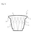
- the plastic core may comprise a frame of wire or plastic with stabilizing cables, hoses or wires.
- the plastic core may comprise a stabilizing tissue insert.
- Fig. 1 shows a schematic cross-section through an embodiment of the solid tire according to the invention 1.
- the solid tire 1 comprises a tread 2 and a tire sidewall 3. Between the tread 2 and the tire sidewall 3, the shoulders 4 are provided on both sides of the solid tire 1. Through these shoulders 4, the width 5 in the region of the shoulder 4 is significantly higher than the width 6 in the region of the tire sidewall 3. Furthermore, it can be seen that the outer surface of the shoulder 4 with a central axis 17 of the solid tire 1 includes a first angle 18 which is greater than 30 °, and with the tread 2 includes a second angle 19 which is smaller than 30 °.
- the tread 2 has along its width a rounding 7, which, however, is significantly lower than in conventional solid tires. In the present embodiment, the rounding 7 is less than 2 °. This ensures that the bearing surface of the tire is much higher than in a conventional solid tire.
- the solid tire 1 has the inner ring 8. This is made of a rigid material and allows a significant material savings and weight reduction.
- Fig. 2 shows a plan view of the inner ring according to the invention 8. This is flexible, but pressure-stable. For this reason, it is provided with a profiling 16, as is known for example from hoses for electrical installations. The profiling also ensures a good connection of the inner ring 8 with the material of the solid tire. 1
- the invention relates both to the solid tire according to the invention, as well as to an impeller which comprises a solid tire according to the invention.
- the connection of the solid tire with the rim of the impeller is irrelevant, the solid tire can be plugged, for example, screwed onto the rim, or be sprayed.
- the invention also extends to a one-piece impeller, in which the rim and the solid tire is manufactured in one operation.
Landscapes
- Engineering & Computer Science (AREA)
- Mechanical Engineering (AREA)
- Tires In General (AREA)
Abstract
Description
- Die Erfindung betrifft einen Vollreifen für Kleinfahrzeuge mit einer profilierten Lauffläche und einer Reifenflanke.
- Für Kleinfahrzeuge wie insbesondere Schubkarren, Golfcaddies, Kinderwägen oder dergleichen sind Vollreifen bekannt, welche eine profilierte Lauffläche und eine, mit der Felge in Kontakt stehende Reifenflanke aufweisen. Vollreifen haben im Vergleich zu herkömmlichen Luftreifen den Vorteil höherer Robustheit.
- Der Ausdruck Vollreifen bezeichnet in diesem Zusammenhang mehr oder weniger massive Reifen, die im Gegensatz zu Luftreifen keine unter Druck stehende Luft oder andere unter Druck stehende Gase enthalten, sondern ihre stoßdämpfenden bzw. federnden Eigenschaften aufgrund ihrer Herstellung aus einem mehr oder weniger elastischen Material beziehen.
- Beispielsweise haben übliche Vollreifen für Schubkarren die Maße 400 x 100 mm bzw. 350 x 100 mm. Die Auflagefläche auf dem Untergrund wird also durch die Breite von 100 mm bestimmt. In der Regel verfügen diese Reifen über eine halbkreisförmige Lauffläche. Diese drückt sich jedoch leicht in weiche Untergründe hinein. Ein Fahren auf weichem Untergrund wird dadurch stark erschwert. Ein entsprechendes Laufrad für Schubkarren ist beispielsweise aus der
DE 200 02 656 U1 bekannt. - Bei Luftreifen kann dieses Problem dadurch behoben werden, dass man die Luft etwas entweichen lässt, um eine größere Auflagefläche zu erhalten. Dies ist nur teilweise hilfreich, da der Reifen dadurch "schwimmt" und sich bei höheren Lasten nicht gut kontrollieren lässt. Auf der Baustelle ist es auch nicht einfach, den richtigen Luftdruck einzustellen.
- An einem Arbeitstag wechseln die Gewichte und Untergründe mehrfach. Ein zu niedriger Luftdruck kann auch die Felge schädigen, wenn man damit über Kanten fährt.
- Aus diesem Grund wäre es vorteilhaft, Breitreifen mit einer breiteren, wenig oder gar nicht gewölbten Lauffläche zu verwenden. Dies ist jedoch aufgrund der vorgegebenen Geometrie der Gabel der Schubkarre ausgeschlossen, da sich ein Breitreifen nicht in die vorgegebene Gabel einführen lässt. Weiters hat die Verbreiterung eines Vollreifens eine deutlich höhere Gewichtszunahme zur Folge, als dies beispielsweise bei einem Luftreifen der Fall wäre. Weiters steht man bei einem als Breitreifen ausgeführten Vollreifen mit wenig gewölbter Lauffläche vor dem Problem, dass Kurvenfahrten erschwert werden, da aufgrund der unterschiedlichen Wölbung eine Kante existiert, die sich in einer geneigten Kurvenfahrt in den Untergrund eindrückt.
- Die technische Aufgabe der vorliegenden Erfindung liegt demnach darin, einen verbesserten Vollreifen zu schaffen, der ein Fahren auf weichem Untergrund erleichtert und sich insbesondere auch bei Kurvenfahrten nicht in den Untergrund eindrückt. Der Vollreifen soll ohne übermäßigen zusätzlichen Materialverbrauch herstellbar sein und muss auf bestehende Gabeln von Arbeitsfahrzeugen montierbar sein.
- Diese technische Aufgabe wird erfindungsgemäß dadurch gelöst, dass zwischen der Lauffläche und der Reifenflanke zumindest eine die Lauffläche verbreiternde umlaufende Schulter vorgesehen ist.
- Indem nicht der gesamte Reifen verbreitert wird, sondern nur im Bereich der Lauffläche eine Schulter vorgesehen ist, erreicht man den Vorteil einer größeren Auflagefläche, ohne den Nachteil eines wesentlich erhöhten Gewichts bzw. Materialverbrauchs in Kauf nehmen zu müssen. Darüber hinaus erlaubt die erfindungsgemäße Realisierung des Vollreifens mit Schultern auch, den Vollreifen auf bestehende Gabeln zu montieren, indem der Vollreifen in die Gabel eingefädelt wird.
- Erfindungsgemäß ist vorgesehen, dass die Breite des Vollreifens im Bereich der Schulter, also im Wesentlichen die Breite der den Boden berührenden Lauffläche, um zumindest 30% größer sein kann als die Breite des Vollreifens im Bereich der Reifenflanke. Bei einem üblichen Schubkarrenreifen bedeutet dies, dass die Breite der Lauffläche von 100mm auf 130mm oder mehr erhöht werden kann.
- Erfindungsgemäß ist vorgesehen dass die Schulter eine spitzwinkelige Auswölbung bilden kann. Dazu kann vorgesehen sein, dass die Außenfläche der Schulter mit einer Mittelachse des Vollreifens einen ersten Winkel einschließt, der größer als etwa 30° ist, und mit der Lauffläche einen zweiten Winkel einschließt, der kleiner als etwa 30° ist. Die Erfindung ist jedoch nicht auf die Einhaltung dieser Winkelangaben beschränkt.
- Erfindungsgemäß kann die Lauffläche entlang ihrer Breite eine Rundung mit weniger als 2° aufweisen. Dadurch entsteht eine breite Auflagefläche, die nicht wie ein Keil in den Untergrund drückt. Insbesondere kann vorgesehen sein, dass die Lauffläche entlang ihrer Breite keine Rundung aufweist.
- Durch die Ausführung des Vollreifens mit Schultern, wodurch die Lauffläche breiter ist als die Reifenflanke, wird erreicht, dass man mit diesem Reifen leicht um Kurven fahren kann. Der Reifen wird aufgrund der Schultern zu den Kanten seiner Lauffläche weicher (da weniger abstützendes Material vorhanden ist), und gibt somit in Kurven nach. Diese Weichheit ist besonders auf weichen Rasenflächen von Vorteil, da keine tiefen Laufspuren auftreten.
- Ein weiterer Vorteil ist die Montierbarkeit an Karren, die über eine Gabel verfügen. Hier muss der Reifen durch die Holme geführt und eingespannt werden. Dies wäre nicht möglich, wenn die Reifenflanke die gleiche Breite wie die Mantelfläche besitzt. Meist beträgt die Achsweite 75 - 100 mm. Die Reifenflanke ist ca. 65 - 70 mm breit und verfügt so über die Breite der Felge. Erst kurz vor dem Rand steigt die Breite auf 130 mm. Durch Kippen kann der Reifen schräg zwischen die Gabel geführt werden. In schwierigen Fällen geben die weichen Schultern noch ein wenig nach. Auf diese Weise lässt sich der Reifen auf den meisten gängigen Profischubkarren einsetzen.
- Die geringe Profiltiefe und deren Gestaltung verhindern zusätzlich eine Beschädigung des Rasens. Es ist dennoch möglich, durch Matsch und Schnee zu fahren. Dies wird insbesondere ermöglicht, wenn die Reifen Rillenprofile in Laufrichtung aufweisen. Durch die geringe Profiltiefe setzen sich auch keine kleinen Steine fest.
- Eine breite Mantelfläche mit schaler Reifenflanke wirkt sich in der Produktion positiv aus.
- Hier kann erheblich Material eingespart werden, was zu kürzeren Produktionszeiten führt. Auch das Gewicht ist gegenüber einem gleichdicken Breitenreifen geringer.
- Eine weitere erfindungsgemäße Ausgestaltung des Reifens ergibt sich, wenn der Reifen direkt auf die Felge geschäumt wird. Dadurch entsteht zwischen Schaum und Felge eine feste Verbindung. Der Reifen kann nicht mehr auf der Felge wandern. Das Schieben wird effektiver und es entstehen keine lästigen Knarrgeräusche. Entsprechend erstreckt sich die Erfindung auf ein Laufrad mit einer Felge und einem erfindungsgemäßen Vollreifen, wobei der Vollreifen direkt auf die Felge aufgeschäumt, bzw. mit der Felge direkt in einem Spritzvorgang gefertigt ist.
- Um das Gewicht weiter zu verringern, kann der Reifen mit einem hohlen aber dichten und druckstabilen Innenring versehen werden. Dieser wird anfangs um die Felge gelegt und dann mit dem Reifenmaterial umschäumt. Je nach Durchmesser der Einlage und variieren der Schaumfestigkeit, kann der Reifen auf verschiedene Härten abgestimmt werden. Durch die Einlage erhält der Reifen eine stabile und feste Reifenflanke kombiniert mit einer weichen Mantelfläche.
Der erfindungsgemäße Vollreifen kann also einen hohlen, luftdichten und druckstabilen Innenring umfassen. Der Durchmesser, das Material und die Druckfestigkeit des Innenrings kann vorzugsweise an das Anwendungsgebiet angepasst sein. Insbesondere kann der Innenring als flexibler profilierter Kunststoffschlauch ausgeführt sein. - Es kann erfindungsgemäß vorgesehen sein, dass eine dünne feste Außenschicht von etwa 1 - 2 mm mit einem über den sonst ganzen Querschnitt weicheren Kern vorgesehen ist. Es kann weiters vorgesehen sein, dass zusätzlich ein harter Kern gebildet wird. Zusammen mit handelsüblichen Felgen entstehen so Variationsmöglichkeiten, die mit einer Felge für Niederquerschnittsreifen nicht möglich sind. Zumal ist dieses Vorgehen wirtschaftlicher, da hier das Werkzeug auf einen Felgendurchmesser beschränkt bleibt und nur unterschiedliche Innenringe eingelegt werden können. Der Härtegrad des Kunststoffkerns (Shore-Härte) kann dem jeweiligen Anwendungsgebiet angepasst sein.
- Die Innenringe können aus kostengünstiger Schlauchware hergestellt werden. Durch eine Konstruktion ähnlich der menschlichen Wirbelsäule lässt sich das Material zu Ringen formen und an den Stoßstellen durch geeignete Verfahren dicht verbinden. Bekannt sich solche Schläuche z. B. aus der Elektroinstallation. In dieser Branche dient die Schlauchware als flexibler Kabelschutz. Durch die Wirbelsäulenstruktur wird der Schaum beim Fertigungsprozess regelrecht mit der Schlauchware verzahnt.
- Erfindungsgemäß kann der Vollreifen einen weichen Kunststoffkern und eine harte Kunststoffaußenschicht umfassen. Der Kunststoffkern und/oder die Kunststoffaußenschicht können zumindest teilweise aus Polyurethanschaum gefertigt sein. Dadurch wird der Reifen gestützt, sodass die Schaummasse weich eingestellt, aber die Reifenflanke (der Kern) des Reifens steif bleiben kann.
- Dies kann durch Kabel, Schläuche oder Drähte erreicht werden. Diese können durch ein Draht- bzw. Kunststoffgestell gehalten werden, welches sich innen in der Felge abstützt. Derartige Einlagen sind flexibel und stellen sich nach Auslenkung wieder in ihre ursprüngliche Form. Das haltende Gestell kann so gestaltet sein, dass die Einlagen nach einer Verformung wieder in die Ausgangslage wandern können.
- Eine andere erfindungsgemäße Ausgestaltung stellt eine Gewebeeinlage dar. Vorzugsweise wird diese aus zwei Teilen bestehen, die durch einen vorherigen Umformprozess herstellt werden. Auch hier reagiert das Material flexibel und stellt sich nach Verformung mit dem Schaum zurück.
- Entsprechend kann der Kunststoffkern ein Gestell aus Draht oder Kunststoff mit stabilisierenden Kabeln, Schläuchen oder Drähten umfassen. Alternativ kann der Kunststoffkern eine stabilisierende Gewebeeinlage umfassen.
- Weitere erfindungsgemäße Merkmale sind der Beschreibung, den Zeichnungen und den Ansprüchen zu entnehmen.
- Die Erfindung wird nun anhand von Ausführungsbeispielen in den folgenden Figuren näher beschrieben. Es zeigen
- Fig. 1:
- einen schematischen Querschnitt durch eine erfindungsgemäße Ausführungsform des Vollreifens;
- Fig. 2:
- eine schematische Ansicht eines erfindungsgemäßen Innenrings:
- Fig. 3a-3b:
- eine schematische Aufsicht auf ein erfindungsgemäßes Ausführungsbeispiel des Vollreifens bei der Montage an einer Gabel:
- Fig. 4:
- einen schematischen Querschnitt durch eine weitere erfindungsgemäße Ausführungsform des Vollreifens;
- Fig. 5:
- einen schematischen Querschnitt durch eine weitere erfindungsgemäße Ausführungsform des Vollreifens.
-
Fig. 1 zeigt einen schematischen Querschnitt durch eine erfindungsgemäße Ausführungsform des Vollreifens 1. Der Vollreifen 1 umfasst eine Lauffläche 2 und eine Reifenflanke 3. Zwischen der Lauffläche 2 und der Reifenflanke 3 sind auf beiden Seiten des Vollreifens 1 die Schultern 4 vorgesehen. Durch diese Schultern 4 ist die Breite 5 im Bereich der Schulter 4 deutlich höher als die Breite 6 im Bereich der Reifenflanke 3.
Weiters ist ersichtlich, dass die Außenfläche der Schulter 4 mit einer Mittelachse 17 des Vollreifens 1 einen ersten Winkel 18 einschließt, der größer als 30° ist, und mit der Lauffläche 2 einen zweiten Winkel 19 einschließt, der kleiner als 30° ist.
Die Lauffläche 2 weist entlang ihrer Breite eine Rundung 7 auf, die jedoch deutlich geringer ist als bei herkömmlichen Vollreifen. Im gegenständlichen Ausführungsbeispiel beträgt die Rundung 7 weniger als 2°. Dadurch wird erreicht, dass die Auflagefläche des Reifens wesentlich höher ist als bei einem herkömmlichen Vollreifen. - Weiters verfügt der Vollreifen 1 über den Innenring 8. Dieser ist aus einem steifen Material gefertigt und erlaubt eine deutliche Materialeinsparung und Gewichtsreduktion.
-
Fig. 2 zeigt eine Aufsicht auf den erfindungsgemäßen Innenring 8. Dieser ist biegsam, aber druckstabil. Aus diesem Grund ist er mit einer Profilierung 16 versehen, wie dies beispielsweise aus Schläuchen für Elektroinstallationen bekannt ist. Die Profilierung sorgt auch für eine gute Verbindung des Innenrings 8 mit dem Material des Vollreifens 1. - Die
Figuren 3a und 3b zeigen den Montagevorgang eines erfindungsgemäßen Vollreifens 1, der auf einer Felge 14 montiert ist, wodurch das Laufrad 13 gebildet ist, auf einer Gabel 15 eines Fahrzeugs. Aufgrund der Form der Schultern 4 kann das Laufrad 13 in die Gabel eingefädelt werden, obwohl die Lauffläche 2 deutlich breiter ist als die Aussparung der Gabel 15. -
Fig. 4 zeigt einen schematischen Querschnitt durch eine weitere erfindungsgemäße Ausführungsform des Vollreifens 1. Der Vollreifen 1 umfasst einen weichen Kunststoffkern 9 und eine harte Kunststoffaußenschicht 10. Im Inneren des Kunststoffkerns 9 befindet sich eine stabilisierende Gewebeeinlage 12. Die Gewebeeinlage 12 ist vom Kunststoffkern 9 durchdrungen. -
Fig. 5 zeigt einen schematischen Querschnitt durch eine weitere erfindungsgemäße Ausführungsform des Vollreifens 1. Der Vollreifen 1 umfasst einen weichen Kunststoffkern 9 und eine harte Kunststoffaußenschicht 10. Im Inneren des Kunststoffkerns 9 befindet sich ein stabilisierendes Gestell 11, beispielsweise ein Draht- oder Kunststoffgestell. Das Gestell 11 ist vom Kunststoffkern durchdrungen. - Die Erfindung bezieht sich sowohl auf den erfindungsgemäßen Vollreifen, als auch auf ein Laufrad welches einen erfindungsgemäßen Vollreifen umfasst. Dabei ist die Verbindung des Vollreifens mit der Felge des Laufrads unerheblich, der Vollreifen kann beispielsweise auf die Felge aufgesteckt, aufgeschraubt, oder aufgespritzt sein. Weiters erstreckt sich die Erfindung auch auf ein einstückiges Laufrad, bei welchem die Felge und der Vollreifen in einem Arbeitsgang gefertigt wird.
-
- 1
- Vollreifen
- 2
- Laufffäche
- 3
- Reifenflanke
- 4
- Schulter
- 5
- Breite des Vollreifens im Bereich der Schulter
- 6
- Breite des Vollreifens im Bereich der Reifenflanke
- 7
- Rundung
- 8
- Innenring
- 9
- Kunststoffkern
- 10
- Kunststoffaußenschicht
- 11
- Gestell
- 12
- Gewebeeinlage
- 13
- Laufrad
- 14
- Felge
- 15
- Gabel
- 16
- Profilierung
- 17
- Mittelachse
Claims (15)
- Vollreifen (1) für Kleinfahrzeuge mit einer profilierten Lauffläche (2) und einer Reifenflanke (3), dadurch gekennzeichnet, dass zwischen der Lauffläche (2) und der Reifenflanke (3) zumindest eine die Lauffläche (2) verbreiternde umlaufende Schulter (4) vorgesehen ist.
- Vollreifen (1) nach Anspruch 1, dadurch gekennzeichnet, dass die Breite (5) des Vollreifens (1) im Bereich der Schulter (4) um zumindest 30% größer ist als die Breite (6) des Vollreifens (1) im Bereich der Reifenflanke (3).
- Vollreifen (1) nach Anspruch 1 oder 2, dadurch gekennzeichnet, dass die Außenfläche der Schulter (4) mit einer Mittelachse (17) des Vollreifens (1) einen ersten Winkel (18) einschließt, der größer als 30° ist, und mit der Lauffläche (2) einen zweiten Winkel (19) einschließt, der kleiner als 30° ist.
- Vollreifen (1) nach einem der Ansprüche 1 bis 3, dadurch gekennzeichnet, dass die Lauffläche (2) entlang ihrer Breite eine Rundung (7) mit weniger als 2° oder keine Rundung aufweist.
- Vollreifen (1) nach einem der Ansprüche 1 bis 4, dadurch gekennzeichnet, dass der Vollreifen (1) einen hohlen, luftdichten und druckstabilen Innenring (8) umfasst.
- Vollreifen nach Anspruch 5, dadurch gekennzeichnet, dass der Durchmesser, das Material und die Druckfestigkeit des Innenrings (8) an das Anwendungsgebiet angepasst ist.
- Vollreifen nach Anspruch 5 oder 6, dadurch gekennzeichnet, dass der Innenring (8) als flexibler Kunststoffschlauch ausgeführt ist.
- Vollreifen nach einem der Ansprüche 5 bis 7, dadurch gekennzeichnet, dass der Innenring (8) eine Profilierung (16) aufweist.
- Vollreifen nach einem der Ansprüche 1 bis 8, dadurch gekennzeichnet, dass der Vollreifen (1) einen weichen Kunststoffkern (9) und eine harte Kunststoffaußenschicht (10) umfasst.
- Vollreifen nach Anspruch 9, dadurch gekennzeichnet, dass der Kunststoffkern (9) und/oder die Kunststoffaußenschicht (10) zumindest teilweise aus Polyurethanschaum gefertigt ist.
- Vollreifen nach Anspruch 9 oder 10, dadurch gekennzeichnet, dass der Kunststoffkern (9) ein Gestell (11) aus Draht oder Kunststoff mit stabilisierenden Kabeln, Schläuchen oder Drähten umfasst.
- Vollreifen nach Anspruch 9 oder 10, dadurch gekennzeichnet, dass der Kunststoffkern (9) eine stabilisierende Gewebeeinlage (12) umfasst.
- Vollreifen nach einem der Ansprüche 9 bis 12, dadurch gekennzeichnet, dass der Härtegrad des Kunststoffkerns (9) dem jeweiligen Anwendungsgebiet angepasst ist.
- Laufrad (13) mit einer Felge (14) und einem Vollreifen (1) gemäß einem der Ansprüche 1 bis 13.
- Laufrad (13) mit einer Felge (14) und einem Vollreifen (1) gemäß einem der Ansprüche 1 bis 13, dadurch gekennzeichnet, dass der Vollreifen (1) mit der Felge (14) direkt in einem Spritzvorgang gefertigt ist.
Applications Claiming Priority (1)
| Application Number | Priority Date | Filing Date | Title |
|---|---|---|---|
| DE102011008529A DE102011008529A1 (de) | 2011-01-13 | 2011-01-13 | Vollreifen |
Publications (3)
| Publication Number | Publication Date |
|---|---|
| EP2476563A2 true EP2476563A2 (de) | 2012-07-18 |
| EP2476563A3 EP2476563A3 (de) | 2012-08-29 |
| EP2476563B1 EP2476563B1 (de) | 2019-09-11 |
Family
ID=45495737
Family Applications (1)
| Application Number | Title | Priority Date | Filing Date |
|---|---|---|---|
| EP12150123.3A Active EP2476563B1 (de) | 2011-01-13 | 2012-01-04 | Vollreifen |
Country Status (2)
| Country | Link |
|---|---|
| EP (1) | EP2476563B1 (de) |
| DE (1) | DE102011008529A1 (de) |
Families Citing this family (1)
| Publication number | Priority date | Publication date | Assignee | Title |
|---|---|---|---|---|
| JP6827880B2 (ja) | 2017-05-11 | 2021-02-10 | 株式会社ブリヂストン | 非空気入りタイヤ |
Citations (1)
| Publication number | Priority date | Publication date | Assignee | Title |
|---|---|---|---|---|
| DE20002656U1 (de) | 2000-02-14 | 2000-04-13 | BTS Bau TechnischeSysteme GmbH & Co. KG, 45731 Waltrop | Laufrad für Schubkarren o.dgl. |
Family Cites Families (6)
| Publication number | Priority date | Publication date | Assignee | Title |
|---|---|---|---|---|
| DE855810C (de) * | 1950-08-06 | 1952-11-17 | Gottfried Kiewitt | Elastischer Radreifen, insbesondere fuer Kraftfahrzeuge |
| GB879525A (en) * | 1959-06-04 | 1961-10-11 | Henry Bugden | Improvements in or relating to tyres for vehicles |
| US4362202A (en) * | 1981-03-30 | 1982-12-07 | Sun Metal Products, Inc. | Semi-pneumatic tire |
| FR2600947B1 (fr) * | 1986-07-04 | 1989-03-03 | Someca | Perfectionnements apportes aux roues de brouettes et analogues |
| US6431235B1 (en) * | 2000-05-11 | 2002-08-13 | Richard A. Steinke | Non-pneumatic tire and rim combination |
| US20030024622A1 (en) * | 2001-05-04 | 2003-02-06 | Chrobak Dennis S. | Anisotropic homogeneous elastomeric closed torus tire design & method of manufacture |
-
2011
- 2011-01-13 DE DE102011008529A patent/DE102011008529A1/de not_active Withdrawn
-
2012
- 2012-01-04 EP EP12150123.3A patent/EP2476563B1/de active Active
Patent Citations (1)
| Publication number | Priority date | Publication date | Assignee | Title |
|---|---|---|---|---|
| DE20002656U1 (de) | 2000-02-14 | 2000-04-13 | BTS Bau TechnischeSysteme GmbH & Co. KG, 45731 Waltrop | Laufrad für Schubkarren o.dgl. |
Also Published As
| Publication number | Publication date |
|---|---|
| DE102011008529A1 (de) | 2012-07-19 |
| EP2476563B1 (de) | 2019-09-11 |
| EP2476563A3 (de) | 2012-08-29 |
Similar Documents
| Publication | Publication Date | Title |
|---|---|---|
| DE102010020744B4 (de) | Luftreifen | |
| EP2456995B1 (de) | Verbund von elastomerlager und einer dieses umgebenden hülse | |
| EP3337680B1 (de) | Fahrzeugluftreifen | |
| DE19650314A1 (de) | Rad mit einem austauschbar/dauerhaft eingeschlossenen Ringmaterial | |
| DE3629270A1 (de) | Vorrichtung zum verschleissfreien formen masshaltiger blechbauteile mit zumindest annaehernd l-foermigem oder u-foermigem querschnitt aus blechzuschnitten oder blechteilen | |
| DE102017118384A1 (de) | Sich selbsttätig fortbewegendes Bodenbearbeitungsgerät | |
| DE112011100908T5 (de) | Luftreifen | |
| DE202013105002U1 (de) | Achslenker für ein Fahrwerk eines Fahrzeugs | |
| DE102012103944A1 (de) | Laufstreifenprofil eines Fahrzeugreifens | |
| EP2476563B1 (de) | Vollreifen | |
| EP2692542A1 (de) | Reifen-Zierring | |
| EP2880333B1 (de) | Profilstab und daraus hergestellte fahrzeugfeder | |
| DE102012018883B4 (de) | Zusatzfeder | |
| EP3041385B1 (de) | Laufrolle | |
| DE102010010487B4 (de) | Käfig für Kugelgelenk und Kugelgelenk | |
| DE102012009012A1 (de) | Parabel-Lenkerfeder und Verfahren zu deren Herstellung | |
| DE2803134A1 (de) | Bereifung fuer mehrfach bereifte fahrzeuge | |
| DE102017101038A1 (de) | Axiallager zur Lagerung eines Achsschenkels sowie Achsschenkellageranordnung mit dem Axiallager | |
| DE102015212874A1 (de) | Fahrzeugluftreifen | |
| EP2562447B1 (de) | Schaltgabel | |
| EP2918857B1 (de) | Stange für Verbindungsstützen | |
| EP2676591A1 (de) | Bodenstaubsauger mit wenigstens einer drehbar gelagerten Lenkrolleneinheit | |
| DE2044995A1 (de) | Ringförmige Reifeneinlage fur Fahr zeugreifen | |
| AT521084B1 (de) | Profilstab und daraus hergestellte Fahrzeugfeder | |
| DE102012012994A1 (de) | Lenker einer Radaufhängung |
Legal Events
| Date | Code | Title | Description |
|---|---|---|---|
| PUAI | Public reference made under article 153(3) epc to a published international application that has entered the european phase |
Free format text: ORIGINAL CODE: 0009012 |
|
| AK | Designated contracting states |
Kind code of ref document: A2 Designated state(s): AL AT BE BG CH CY CZ DE DK EE ES FI FR GB GR HR HU IE IS IT LI LT LU LV MC MK MT NL NO PL PT RO RS SE SI SK SM TR |
|
| AX | Request for extension of the european patent |
Extension state: BA ME |
|
| PUAL | Search report despatched |
Free format text: ORIGINAL CODE: 0009013 |
|
| AK | Designated contracting states |
Kind code of ref document: A3 Designated state(s): AL AT BE BG CH CY CZ DE DK EE ES FI FR GB GR HR HU IE IS IT LI LT LU LV MC MK MT NL NO PL PT RO RS SE SI SK SM TR |
|
| AX | Request for extension of the european patent |
Extension state: BA ME |
|
| RIC1 | Information provided on ipc code assigned before grant |
Ipc: B60C 7/12 20060101AFI20120724BHEP Ipc: B60C 7/22 20060101ALI20120724BHEP Ipc: B60C 11/01 20060101ALI20120724BHEP |
|
| 17P | Request for examination filed |
Effective date: 20130117 |
|
| 17Q | First examination report despatched |
Effective date: 20130307 |
|
| STAA | Information on the status of an ep patent application or granted ep patent |
Free format text: STATUS: EXAMINATION IS IN PROGRESS |
|
| RIC1 | Information provided on ipc code assigned before grant |
Ipc: B60C 7/12 20060101AFI20181212BHEP Ipc: B60C 7/10 20060101ALI20181212BHEP Ipc: B60C 7/22 20060101ALI20181212BHEP Ipc: B60C 11/01 20060101ALI20181212BHEP |
|
| GRAP | Despatch of communication of intention to grant a patent |
Free format text: ORIGINAL CODE: EPIDOSNIGR1 |
|
| STAA | Information on the status of an ep patent application or granted ep patent |
Free format text: STATUS: GRANT OF PATENT IS INTENDED |
|
| INTG | Intention to grant announced |
Effective date: 20190320 |
|
| GRAS | Grant fee paid |
Free format text: ORIGINAL CODE: EPIDOSNIGR3 |
|
| GRAA | (expected) grant |
Free format text: ORIGINAL CODE: 0009210 |
|
| STAA | Information on the status of an ep patent application or granted ep patent |
Free format text: STATUS: THE PATENT HAS BEEN GRANTED |
|
| AK | Designated contracting states |
Kind code of ref document: B1 Designated state(s): AL AT BE BG CH CY CZ DE DK EE ES FI FR GB GR HR HU IE IS IT LI LT LU LV MC MK MT NL NO PL PT RO RS SE SI SK SM TR |
|
| REG | Reference to a national code |
Ref country code: GB Ref legal event code: FG4D Free format text: NOT ENGLISH |
|
| REG | Reference to a national code |
Ref country code: CH Ref legal event code: EP |
|
| REG | Reference to a national code |
Ref country code: AT Ref legal event code: REF Ref document number: 1177959 Country of ref document: AT Kind code of ref document: T Effective date: 20190915 |
|
| REG | Reference to a national code |
Ref country code: DE Ref legal event code: R096 Ref document number: 502012015267 Country of ref document: DE Ref country code: IE Ref legal event code: FG4D Free format text: LANGUAGE OF EP DOCUMENT: GERMAN |
|
| REG | Reference to a national code |
Ref country code: NL Ref legal event code: FP |
|
| REG | Reference to a national code |
Ref country code: LT Ref legal event code: MG4D |
|
| PG25 | Lapsed in a contracting state [announced via postgrant information from national office to epo] |
Ref country code: FI Free format text: LAPSE BECAUSE OF FAILURE TO SUBMIT A TRANSLATION OF THE DESCRIPTION OR TO PAY THE FEE WITHIN THE PRESCRIBED TIME-LIMIT Effective date: 20190911 Ref country code: HR Free format text: LAPSE BECAUSE OF FAILURE TO SUBMIT A TRANSLATION OF THE DESCRIPTION OR TO PAY THE FEE WITHIN THE PRESCRIBED TIME-LIMIT Effective date: 20190911 Ref country code: SE Free format text: LAPSE BECAUSE OF FAILURE TO SUBMIT A TRANSLATION OF THE DESCRIPTION OR TO PAY THE FEE WITHIN THE PRESCRIBED TIME-LIMIT Effective date: 20190911 Ref country code: NO Free format text: LAPSE BECAUSE OF FAILURE TO SUBMIT A TRANSLATION OF THE DESCRIPTION OR TO PAY THE FEE WITHIN THE PRESCRIBED TIME-LIMIT Effective date: 20191211 Ref country code: LT Free format text: LAPSE BECAUSE OF FAILURE TO SUBMIT A TRANSLATION OF THE DESCRIPTION OR TO PAY THE FEE WITHIN THE PRESCRIBED TIME-LIMIT Effective date: 20190911 Ref country code: BG Free format text: LAPSE BECAUSE OF FAILURE TO SUBMIT A TRANSLATION OF THE DESCRIPTION OR TO PAY THE FEE WITHIN THE PRESCRIBED TIME-LIMIT Effective date: 20191211 |
|
| PG25 | Lapsed in a contracting state [announced via postgrant information from national office to epo] |
Ref country code: LV Free format text: LAPSE BECAUSE OF FAILURE TO SUBMIT A TRANSLATION OF THE DESCRIPTION OR TO PAY THE FEE WITHIN THE PRESCRIBED TIME-LIMIT Effective date: 20190911 Ref country code: ES Free format text: LAPSE BECAUSE OF FAILURE TO SUBMIT A TRANSLATION OF THE DESCRIPTION OR TO PAY THE FEE WITHIN THE PRESCRIBED TIME-LIMIT Effective date: 20190911 Ref country code: AL Free format text: LAPSE BECAUSE OF FAILURE TO SUBMIT A TRANSLATION OF THE DESCRIPTION OR TO PAY THE FEE WITHIN THE PRESCRIBED TIME-LIMIT Effective date: 20190911 Ref country code: GR Free format text: LAPSE BECAUSE OF FAILURE TO SUBMIT A TRANSLATION OF THE DESCRIPTION OR TO PAY THE FEE WITHIN THE PRESCRIBED TIME-LIMIT Effective date: 20191212 Ref country code: RS Free format text: LAPSE BECAUSE OF FAILURE TO SUBMIT A TRANSLATION OF THE DESCRIPTION OR TO PAY THE FEE WITHIN THE PRESCRIBED TIME-LIMIT Effective date: 20190911 |
|
| PG25 | Lapsed in a contracting state [announced via postgrant information from national office to epo] |
Ref country code: PL Free format text: LAPSE BECAUSE OF FAILURE TO SUBMIT A TRANSLATION OF THE DESCRIPTION OR TO PAY THE FEE WITHIN THE PRESCRIBED TIME-LIMIT Effective date: 20190911 Ref country code: EE Free format text: LAPSE BECAUSE OF FAILURE TO SUBMIT A TRANSLATION OF THE DESCRIPTION OR TO PAY THE FEE WITHIN THE PRESCRIBED TIME-LIMIT Effective date: 20190911 Ref country code: RO Free format text: LAPSE BECAUSE OF FAILURE TO SUBMIT A TRANSLATION OF THE DESCRIPTION OR TO PAY THE FEE WITHIN THE PRESCRIBED TIME-LIMIT Effective date: 20190911 Ref country code: PT Free format text: LAPSE BECAUSE OF FAILURE TO SUBMIT A TRANSLATION OF THE DESCRIPTION OR TO PAY THE FEE WITHIN THE PRESCRIBED TIME-LIMIT Effective date: 20200113 Ref country code: IT Free format text: LAPSE BECAUSE OF FAILURE TO SUBMIT A TRANSLATION OF THE DESCRIPTION OR TO PAY THE FEE WITHIN THE PRESCRIBED TIME-LIMIT Effective date: 20190911 |
|
| PG25 | Lapsed in a contracting state [announced via postgrant information from national office to epo] |
Ref country code: SK Free format text: LAPSE BECAUSE OF FAILURE TO SUBMIT A TRANSLATION OF THE DESCRIPTION OR TO PAY THE FEE WITHIN THE PRESCRIBED TIME-LIMIT Effective date: 20190911 Ref country code: CZ Free format text: LAPSE BECAUSE OF FAILURE TO SUBMIT A TRANSLATION OF THE DESCRIPTION OR TO PAY THE FEE WITHIN THE PRESCRIBED TIME-LIMIT Effective date: 20190911 Ref country code: SM Free format text: LAPSE BECAUSE OF FAILURE TO SUBMIT A TRANSLATION OF THE DESCRIPTION OR TO PAY THE FEE WITHIN THE PRESCRIBED TIME-LIMIT Effective date: 20190911 Ref country code: IS Free format text: LAPSE BECAUSE OF FAILURE TO SUBMIT A TRANSLATION OF THE DESCRIPTION OR TO PAY THE FEE WITHIN THE PRESCRIBED TIME-LIMIT Effective date: 20200224 |
|
| REG | Reference to a national code |
Ref country code: DE Ref legal event code: R097 Ref document number: 502012015267 Country of ref document: DE |
|
| PLBE | No opposition filed within time limit |
Free format text: ORIGINAL CODE: 0009261 |
|
| STAA | Information on the status of an ep patent application or granted ep patent |
Free format text: STATUS: NO OPPOSITION FILED WITHIN TIME LIMIT |
|
| PG2D | Information on lapse in contracting state deleted |
Ref country code: IS |
|
| PG25 | Lapsed in a contracting state [announced via postgrant information from national office to epo] |
Ref country code: DK Free format text: LAPSE BECAUSE OF FAILURE TO SUBMIT A TRANSLATION OF THE DESCRIPTION OR TO PAY THE FEE WITHIN THE PRESCRIBED TIME-LIMIT Effective date: 20190911 Ref country code: IS Free format text: LAPSE BECAUSE OF FAILURE TO SUBMIT A TRANSLATION OF THE DESCRIPTION OR TO PAY THE FEE WITHIN THE PRESCRIBED TIME-LIMIT Effective date: 20200112 |
|
| 26N | No opposition filed |
Effective date: 20200615 |
|
| PG25 | Lapsed in a contracting state [announced via postgrant information from national office to epo] |
Ref country code: MC Free format text: LAPSE BECAUSE OF FAILURE TO SUBMIT A TRANSLATION OF THE DESCRIPTION OR TO PAY THE FEE WITHIN THE PRESCRIBED TIME-LIMIT Effective date: 20190911 Ref country code: SI Free format text: LAPSE BECAUSE OF FAILURE TO SUBMIT A TRANSLATION OF THE DESCRIPTION OR TO PAY THE FEE WITHIN THE PRESCRIBED TIME-LIMIT Effective date: 20190911 |
|
| REG | Reference to a national code |
Ref country code: CH Ref legal event code: PL |
|
| GBPC | Gb: european patent ceased through non-payment of renewal fee |
Effective date: 20200104 |
|
| REG | Reference to a national code |
Ref country code: BE Ref legal event code: MM Effective date: 20200131 |
|
| PG25 | Lapsed in a contracting state [announced via postgrant information from national office to epo] |
Ref country code: GB Free format text: LAPSE BECAUSE OF NON-PAYMENT OF DUE FEES Effective date: 20200104 Ref country code: FR Free format text: LAPSE BECAUSE OF NON-PAYMENT OF DUE FEES Effective date: 20200131 Ref country code: LU Free format text: LAPSE BECAUSE OF NON-PAYMENT OF DUE FEES Effective date: 20200104 |
|
| PG25 | Lapsed in a contracting state [announced via postgrant information from national office to epo] |
Ref country code: BE Free format text: LAPSE BECAUSE OF NON-PAYMENT OF DUE FEES Effective date: 20200131 Ref country code: LI Free format text: LAPSE BECAUSE OF NON-PAYMENT OF DUE FEES Effective date: 20200131 Ref country code: CH Free format text: LAPSE BECAUSE OF NON-PAYMENT OF DUE FEES Effective date: 20200131 |
|
| PG25 | Lapsed in a contracting state [announced via postgrant information from national office to epo] |
Ref country code: IE Free format text: LAPSE BECAUSE OF NON-PAYMENT OF DUE FEES Effective date: 20200104 |
|
| PG25 | Lapsed in a contracting state [announced via postgrant information from national office to epo] |
Ref country code: TR Free format text: LAPSE BECAUSE OF FAILURE TO SUBMIT A TRANSLATION OF THE DESCRIPTION OR TO PAY THE FEE WITHIN THE PRESCRIBED TIME-LIMIT Effective date: 20190911 Ref country code: MT Free format text: LAPSE BECAUSE OF FAILURE TO SUBMIT A TRANSLATION OF THE DESCRIPTION OR TO PAY THE FEE WITHIN THE PRESCRIBED TIME-LIMIT Effective date: 20190911 Ref country code: CY Free format text: LAPSE BECAUSE OF FAILURE TO SUBMIT A TRANSLATION OF THE DESCRIPTION OR TO PAY THE FEE WITHIN THE PRESCRIBED TIME-LIMIT Effective date: 20190911 |
|
| PG25 | Lapsed in a contracting state [announced via postgrant information from national office to epo] |
Ref country code: MK Free format text: LAPSE BECAUSE OF FAILURE TO SUBMIT A TRANSLATION OF THE DESCRIPTION OR TO PAY THE FEE WITHIN THE PRESCRIBED TIME-LIMIT Effective date: 20190911 |
|
| PGFP | Annual fee paid to national office [announced via postgrant information from national office to epo] |
Ref country code: NL Payment date: 20260121 Year of fee payment: 15 |
|
| PGFP | Annual fee paid to national office [announced via postgrant information from national office to epo] |
Ref country code: DE Payment date: 20260120 Year of fee payment: 15 |
|
| PGFP | Annual fee paid to national office [announced via postgrant information from national office to epo] |
Ref country code: AT Payment date: 20260119 Year of fee payment: 15 |