EP2476609A2 - Frein de bicyclette - Google Patents
Frein de bicyclette Download PDFInfo
- Publication number
- EP2476609A2 EP2476609A2 EP11010047A EP11010047A EP2476609A2 EP 2476609 A2 EP2476609 A2 EP 2476609A2 EP 11010047 A EP11010047 A EP 11010047A EP 11010047 A EP11010047 A EP 11010047A EP 2476609 A2 EP2476609 A2 EP 2476609A2
- Authority
- EP
- European Patent Office
- Prior art keywords
- brake arm
- brake
- transfer
- cable
- arm
- Prior art date
- Legal status (The legal status is an assumption and is not a legal conclusion. Google has not performed a legal analysis and makes no representation as to the accuracy of the status listed.)
- Withdrawn
Links
- 238000012986 modification Methods 0.000 description 2
- 230000004048 modification Effects 0.000 description 2
- 230000000717 retained effect Effects 0.000 description 1
Images


Classifications
-
- B—PERFORMING OPERATIONS; TRANSPORTING
- B62—LAND VEHICLES FOR TRAVELLING OTHERWISE THAN ON RAILS
- B62L—BRAKES SPECIALLY ADAPTED FOR CYCLES
- B62L1/00—Brakes; Arrangements thereof
- B62L1/02—Brakes; Arrangements thereof in which cycle wheels are engaged by brake elements
- B62L1/06—Brakes; Arrangements thereof in which cycle wheels are engaged by brake elements the wheel rim being engaged
- B62L1/10—Brakes; Arrangements thereof in which cycle wheels are engaged by brake elements the wheel rim being engaged by the elements moving substantially parallel to the wheel axis
- B62L1/12—Brakes; Arrangements thereof in which cycle wheels are engaged by brake elements the wheel rim being engaged by the elements moving substantially parallel to the wheel axis the elements being mounted on levers pivotable about a common axis
Definitions
- the invention pertains to vehicles such as bicycles, and to brake systems for bicycles.
- Bicycle braking systems are known in the art. Some of these systems are cable actuated and utilize a caliper system mounted to a frame or fork of the bicycle.
- the caliper system has two pivoting main arms, each supporting a brake pad positioned on opposing sides of the wheel rim. Actuation of the cable causes the arms to pivot about a mounting point(s) such that the brake pads move together toward each other to apply a braking force to the wheel.
- a bicycle brake actuated by a control cable comprises: a first main brake arm having a cable guide for receiving the control cable; a second main brake arm mounted for pivotable movement with respect to the first main brake arm; a first transfer brake arm pivotally connected to the first main brake arm, the first transfer brake arm having a cable anchor for receiving the control cable, the control cable extending between the cable guide and the cable anchor; and a second transfer brake arm pivotally connected to the first transfer brake arm and pivotally connected to the second main brake arm.
- the first transfer brake arm also comprises a cable anchor that releasably retains the brake cable, wherein the pivotal connection between the second transfer brake arm and the first transfer brake arm is disposed on the first transfer brake arm between (i) the pivotal connection of the first transfer brake arm to the first main brake arm and (ii) the cable anchor.
- the first main brake arm has a cable guide that retains the cable housing and allows the brake cable to extend through the cable guide to the cable anchor.
- the first main brake arm has a first mounting bore and the second main brake arm has a second mounting bore and a fastener passes through the first mounting bore and the second mounting bore to fasten the bicycle brake to a bicycle frame.
- the first main brake arm has a first end that supports a first brake shoe
- the second main brake arm has a second end that supports a second brake shoe
- the second mounting bore is disposed between (i) the second end of the second main brake arm and (ii) the pivotal connection of the second transfer brake arm to the second main brake arm.
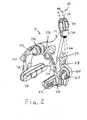
- the bicycle brake 10 includes a first main brake arm 12 and a second main brake arm 14.
- the bicycle brake also includes a first transfer brake arm 16 and a second transfer brake arm 18.
- the first main brake arm 12 has a first mounting bore 20 and the second main brake arm 14 has a second mounting bore 22 which permit the brake arms to be mounted to the frame of a bicycle.
- a single fastener or mounting bolt 24 passes through the bores 20 and 22 and is fastened to the bicycle frame.
- a bias spring 26 is attached to a grommet 28 which the mounting bolt 24 also passes through.
- the mounting bolt 24 supports the bias spring 26 so that its respective ends contact a spring mounting boss 30 on the first main brake arm 12 and a spring mounting boss 32 on the second main brake arm 14.
- the bias spring 26 therefore biases the first and second main brake arms 12 and 14, and their respective brake pads 72, 76, apart from each other.
- the first main brake arm 12 has a cable guide 34 which receives a control cable 35, in this embodiment a Bowden-type cable.
- the control cable 35 includes a cable housing 38 and a brake cable 66 slidably disposed in the cable housing 38.
- the cable guide 34 includes a seat that retains the cable housing 38 and allows the brake cable 66 to extend through the cable guide 34.
- the cable guide 34 includes a barrel adjuster 36 for adjusting the length of the brake cable 66.
- the first transfer brake arm 16 is pivotally connected to the first main brake arm 12 by a first pivot pin 40 extending through a bore 42 in the first main brake arm 12 and a bore 44 in the first transfer brake arm 16.
- the second transfer brake arm 18 is connected to the second main brake arm 14 by a second pivot pin 46 extending through a bore 48 in the second main brake arm 14 and a bore 50 in the second main brake arm 14.
- a second transfer brake arm 18 is connected to the first transfer brake arm 16 by a third pivot pin 54 which extends through a bore 56 in the second transfer brake arm 18 and a bore 58 in the first transfer brake arm 16.
- the first transfer brake arm 16 therefore is pivotally connected to both the first main brake arm 12 and to the second transfer brake arm 18.
- the first transfer brake arm 16 has, at its projecting end, a cable engaging feature that engages the brake cable 66 so that brake cable force is transferred to the first transfer brake arm 16.
- the first transfer brake arm 16 has an aperture 60 therethrough.
- the aperture 60 serves as a female cable bore that receives a cable anchor 62.
- the cable anchor 62 is a clamp that retains an end portion of the brake cable 66.
- the cable anchor 62 may be of a quick release type that can quickly latch on to or release the cable 66.
- the first transfer brake arm 16 has the cable guide 34 and the first main brake arm 12 has the cable anchor 62.
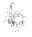
- the first main brake arm 12 terminates in a lower extension 70 which supports a brake pad 72.
- the second main brake arm 14 terminates in a lower extension 74 which supports a brake pad 76.
- FIGS. 4 and 5 also schematically depict a wheel rim 99.
- the brake actuation sequence is initiated by pulling on or tensioning the brake cable 66 by means of a purposed cable pulling mechanism, such as a brake lever.
- a purposed cable pulling mechanism such as a brake lever.
- the brake cable housing 38 is retained relative to the cable guide 34.
- the cable 66 is thus drawn upward applying the upward tensile force at the female cable bore 60.
- the first transfer brake arm 16 rotates clockwise about first pivot pin 40, as well as clockwise about an instant center that can be approximated by the location of the third pivot pin 54.
- the first pivot pin 40 allows the transfer force to the first main brake arm 12, displacing the first main brake arm 12 counterclockwise about the mounting bolt 24.
- the first transfer brake arm 16 transfers a compressive force to the second transfer brake arm 18 driving it upwards, by means of the pivotal connection at the third pivot pin 54.
- the brake lever is released, the brake tension in the cable 66 is relaxed, and the bias spring 26 biases the main brake arms 12, 14 and their respective brake pads 72, 76 apart.
- first and second main brake arms 12 and 14, as well as the first and second transfer brake arms 16 and 18 can function in some embodiments as a link, so that those four elements form a linkage.
- the illustrated embodiment features pin connections between the links, other pivotal connections may be used.
Landscapes
- Engineering & Computer Science (AREA)
- Mechanical Engineering (AREA)
- Braking Arrangements (AREA)
- Transmission Of Braking Force In Braking Systems (AREA)
- Steering Devices For Bicycles And Motorcycles (AREA)
Applications Claiming Priority (1)
| Application Number | Priority Date | Filing Date | Title |
|---|---|---|---|
| US13/006,183 US8485320B2 (en) | 2011-01-13 | 2011-01-13 | Bicycle brake |
Publications (2)
| Publication Number | Publication Date |
|---|---|
| EP2476609A2 true EP2476609A2 (fr) | 2012-07-18 |
| EP2476609A3 EP2476609A3 (fr) | 2013-11-13 |
Family
ID=45464199
Family Applications (1)
| Application Number | Title | Priority Date | Filing Date |
|---|---|---|---|
| EP11010047.6A Withdrawn EP2476609A3 (fr) | 2011-01-13 | 2011-12-21 | Frein de bicyclette |
Country Status (5)
| Country | Link |
|---|---|
| US (1) | US8485320B2 (fr) |
| EP (1) | EP2476609A3 (fr) |
| CN (1) | CN102582442A (fr) |
| DE (1) | DE102012000244A1 (fr) |
| TW (1) | TWI482720B (fr) |
Families Citing this family (9)
| Publication number | Priority date | Publication date | Assignee | Title |
|---|---|---|---|---|
| US20140190775A1 (en) * | 2013-01-10 | 2014-07-10 | Felt Racing, Llc | Brake having custom kinematics and wide range adjustability for wide and narrow rims |
| US9145186B2 (en) * | 2014-04-29 | 2015-09-29 | Tektro Technology Corporation | Quick-release device of bicycle brake cable |
| TWI537172B (zh) * | 2015-03-24 | 2016-06-11 | 溫芫鋐 | 自行車刹車器 |
| US10189537B2 (en) | 2015-03-24 | 2019-01-29 | Yuan-Hung WEN | Brake for bicycle |
| EP3112243B1 (fr) * | 2015-06-30 | 2020-04-08 | Campagnolo S.R.L. | Frein de bicyclette |
| US9821880B2 (en) * | 2015-08-07 | 2017-11-21 | Shimano Inc. | Bicycle rim brake |
| NL2017387B1 (en) * | 2016-08-30 | 2018-03-08 | Just Ride B V | Bicycle brake with lever system, comprising an adjustment member |
| US11377168B2 (en) | 2018-08-01 | 2022-07-05 | Pacific Cycle, Llc | Brake caliper |
| USD908564S1 (en) | 2019-07-29 | 2021-01-26 | Pacific Cycle, Llc | Brake caliper lever assembly |
Family Cites Families (13)
| Publication number | Priority date | Publication date | Assignee | Title |
|---|---|---|---|---|
| GB433377A (en) * | 1934-02-14 | 1935-08-14 | J A Phillips & Co Ltd | Improvements in and relating to brakes for cycles, motor cycles and the like |
| FR1013460A (fr) * | 1950-03-03 | 1952-07-29 | Procédé de commande de frein à mâchoires pour cycles et autres | |
| US3628635A (en) | 1969-05-10 | 1971-12-21 | Kiyokazu Yoshigai | Bicycle brake |
| US4290507A (en) * | 1978-02-15 | 1981-09-22 | Brown Lawrence G | Actuating system and apparatus for brakes and clutches and the like |
| JPH0314462Y2 (fr) * | 1985-12-19 | 1991-03-29 | ||
| DE4025708A1 (de) * | 1990-08-14 | 1992-02-20 | Fichtel & Sachs Ag | Anordnung von gesperreklinken in fahrradnaben |
| CN1081567C (zh) * | 1993-07-11 | 2002-03-27 | 李雄飞 | 强力防崩线闸 |
| JP3279169B2 (ja) * | 1996-04-02 | 2002-04-30 | 株式会社シマノ | シューホルダ |
| US7000739B2 (en) | 2002-10-07 | 2006-02-21 | Ciamillo Theodore J | Cam assisted wheel brake |
| US7422090B1 (en) | 2007-07-24 | 2008-09-09 | Adam Preuss | Caliper brake assembly |
| US7975810B2 (en) | 2007-08-10 | 2011-07-12 | Liu Robert Z | Cam activated bicycle wheel brake |
| TW201034902A (en) * | 2009-03-16 | 2010-10-01 | R Ginster Nicholas | Structure of link lever for bicycle brake |
| TWM384824U (en) * | 2010-02-11 | 2010-07-21 | Sheng-Yao Yang | Cellular type brake clip device |
-
2011
- 2011-01-13 US US13/006,183 patent/US8485320B2/en not_active Expired - Fee Related
- 2011-12-20 TW TW100147465A patent/TWI482720B/zh active
- 2011-12-21 EP EP11010047.6A patent/EP2476609A3/fr not_active Withdrawn
-
2012
- 2012-01-09 DE DE102012000244A patent/DE102012000244A1/de active Pending
- 2012-01-12 CN CN2012100091001A patent/CN102582442A/zh active Pending
Non-Patent Citations (1)
| Title |
|---|
| None |
Also Published As
| Publication number | Publication date |
|---|---|
| EP2476609A3 (fr) | 2013-11-13 |
| TW201233581A (en) | 2012-08-16 |
| US8485320B2 (en) | 2013-07-16 |
| DE102012000244A1 (de) | 2012-07-19 |
| US20120181120A1 (en) | 2012-07-19 |
| TWI482720B (zh) | 2015-05-01 |
| CN102582442A (zh) | 2012-07-18 |
Similar Documents
| Publication | Publication Date | Title |
|---|---|---|
| US8485320B2 (en) | Bicycle brake | |
| US8505694B2 (en) | Link unit of brake assembly for bicycles | |
| US8413769B2 (en) | Bicycle brake system using cam mechanism | |
| US9567032B2 (en) | Brake caliper arrangement structure for motorcycle | |
| US9321501B1 (en) | Bicycle control device | |
| CN110023184B (zh) | 同步制动系统 | |
| CN101323344B (zh) | 自行车盘式车闸装置 | |
| US10183724B2 (en) | Bicycle hydraulic operating system | |
| CN104875835B (zh) | 摩托车 | |
| US9233731B1 (en) | Bicycle rim brake | |
| EP3069981B1 (fr) | Motocyclette | |
| US20080202866A1 (en) | Bicycle brake | |
| US8056682B2 (en) | Bicycle brake device | |
| EP2444310B1 (fr) | Système de frein de bicyclette utilisant un mécanisme de came | |
| US7422090B1 (en) | Caliper brake assembly | |
| WO2016108247A1 (fr) | Système de freinage synchronisé | |
| US7464798B2 (en) | Hydraulic bicycle brake mechanism | |
| US6607056B2 (en) | Brake apparatus for a bicycle and bicycle comprising this apparatus | |
| KR101217587B1 (ko) | 주차 브레이크용 장력조절장치 | |
| WO2011037669A1 (fr) | Système et procédé de freinage et véhicule à deux roues utilisant ce dernier | |
| US8657077B2 (en) | Cantilever brake with quick release mechanism | |
| JPH10338183A (ja) | バーハンドル車両用ブレーキ装置 | |
| CN101460759A (zh) | 鼓式制动器 | |
| JPH0516863A (ja) | 自転車用のブレーキ操作装置 | |
| EP2159152B1 (fr) | Dispositif de freinage pour bicyclette |
Legal Events
| Date | Code | Title | Description |
|---|---|---|---|
| PUAI | Public reference made under article 153(3) epc to a published international application that has entered the european phase |
Free format text: ORIGINAL CODE: 0009012 |
|
| AK | Designated contracting states |
Kind code of ref document: A2 Designated state(s): AL AT BE BG CH CY CZ DE DK EE ES FI FR GB GR HR HU IE IS IT LI LT LU LV MC MK MT NL NO PL PT RO RS SE SI SK SM TR |
|
| AX | Request for extension of the european patent |
Extension state: BA ME |
|
| PUAL | Search report despatched |
Free format text: ORIGINAL CODE: 0009013 |
|
| AK | Designated contracting states |
Kind code of ref document: A3 Designated state(s): AL AT BE BG CH CY CZ DE DK EE ES FI FR GB GR HR HU IE IS IT LI LT LU LV MC MK MT NL NO PL PT RO RS SE SI SK SM TR |
|
| AX | Request for extension of the european patent |
Extension state: BA ME |
|
| RIC1 | Information provided on ipc code assigned before grant |
Ipc: B62L 1/12 20060101AFI20131004BHEP |
|
| 17P | Request for examination filed |
Effective date: 20140506 |
|
| RBV | Designated contracting states (corrected) |
Designated state(s): AL AT BE BG CH CY CZ DE DK EE ES FI FR GB GR HR HU IE IS IT LI LT LU LV MC MK MT NL NO PL PT RO RS SE SI SK SM TR |
|
| 17Q | First examination report despatched |
Effective date: 20141126 |
|
| STAA | Information on the status of an ep patent application or granted ep patent |
Free format text: STATUS: THE APPLICATION IS DEEMED TO BE WITHDRAWN |
|
| 18D | Application deemed to be withdrawn |
Effective date: 20150408 |